


32-Bit TX System RISC
TX19 Family
TMP1940CYAF/TMP1940FDBF

MIPS16, application Specific Extensions and R3000A are a trademark of MIPS
Technologies, Inc.
The information contained herein is subject to change without notice.
The information contained herein is presented only as a guide for the applications of our
products. No responsibility is assumed by TOSHIBA for any infringements of patents or
other rights of the third parties which may result from its use. No license is granted by
implication or otherwise under any patent or patent rights of TOSHIBA or others.
The products described in this document contain components made in the United States
and subject to export control of the U.S. authorities. Diversion contrary to the U.S. law
is prohibited.
TOSHIBA is continually working to improve the quality and reliability of its products.
Nevertheless, semiconductor devices in general can malfunction or fail due to their
inherent electrical sensitivity and vulnerability to physical stress.
It is the responsibility of the buyer, when utilizing TOSHIBA products, to comply with
the standards of safety in making a safe design for the entire system, and to avoid
situations in which a malfunction or failure of such TOSHIBA products could cause loss
of human life, bodily injury or damage to property.
In developing your designs, please ensure that TOSHIBA products are used within
specified operating ranges as set forth in the most recent TOSHIBA products
specifications.
Also, please keep in mind the precautions and conditions set forth in the “Handling
Guide for Semiconductor Devices,” or “TOSHIBA Semiconductor Reliability
Handbook” etc..
The Toshiba products listed in this document are intended for usage in general
electronics applications ( computer, personal equipment, office equipment, measuring
equipment, industrial robotics, domestic appliances, etc.).
These Toshiba products are neither intended nor warranted for usage in equipment that
requires extraordinarily high quality and/or reliability or a malfunction or failure of
which may cause loss of human life or bodily injury (“Unintended Usage”). Unintended
Usage include atomic energy control instruments, airplane or spaceship instruments,
transportation instruments, traffic signal instruments, combustion control instruments,
medical instruments, all types of safety devices, etc.. Unintended Usage of Toshiba
products listed in this document shall be made at the customer’s own risk.
The products described in this document may include products subject to the foreign
exchange and foreign trade laws.
© 2002 TOSHIBA CORPORATION
All Rights Reserved

Preface
Toshiba offers a broad range of microcontrollers targeted for both commercial and industrial
applications. The TX System RISC TX19 Family manual contains the detailed specifications of the
TX1940, including the architecture, programming, capabilities, operation, electrical characteristics,
packaging and so forth.
The TX1940 is a high-performance RISC processor based on the R3000A architecture and the MIPS16
Application Specific Extension pioneered by MIPS Technologies, Inc.
Recently, with the ever-growing market for lightweight portable devices, manufacturers of electronic
systems have been seeking cost-effective, single-chip solutions to processor-based applications.
Toshiba has designed the TX1940 to help customers achieve the best cost performance for their
products.


TMP1940
Contents
Handling Precaution
Part 1 TMP1940
TMP1940CYAF
1. Features...................................................................................................................................................................1
2. Signal Descriptions .................................................................................................................................................5
2.1 Pin Assignment..................................................................................................................................................5
2.2 Pin Usage Information.......................................................................................................................................6
3. Core Processor ........................................................................................................................................................9
3.1 Reset Operation.................................................................................................................................................9
4. Memory Map.........................................................................................................................................................10
5. Clock/Standby Control..........................................................................................................................................11
5.1 Clock Generation............................................................................................................ .................................12
5.1.1 Main System Clock.................................................................................................................................12
5.1.2 Subsystem Clock.....................................................................................................................................12
5.1.3 Clock Source Block Diagrams................................................................................................................13
5.2 Clock Generator (CG) Registers......................................................................................................................14
5.2.1 System Clock Control Registers..............................................................................................................14
5.2.2 ADC Conversion Clock ..........................................................................................................................16
5.2.3 STOP/SLEEP Wake-up Interrupt Control Registers (INTCG Registers) ...............................................16
5.2.4 Interrupt Request Clear Register.............................................................................................................18
5.3 System Clock Control Section.........................................................................................................................19
5.3.1 Oscillation Stabilization Time When Switching Between NORMAL and SLOW Modes......................19
5.3.2 System Clock Output..............................................................................................................................20
5.3.3 Reducing the Oscillator Clock Drive Capability.....................................................................................20
5.4 Prescalar Clock Control Section......................................................................................................................21
5.5 Clock Frequency Multiplication Section (PLL)...............................................................................................21
5.6 Standby Control Section..................................................................................................................................22
5.6.1 TMP1940CYAF Operation in NORMAL and Standby Modes...............................................................23
5.6.2 CG Operation in NORMAL and Standby Modes...................................................................................23
5.6.3 Processor and Peripheral Block Operation in Standby Modes................................................................23
5.6.4 Wake-up Signaling..................................................................................................................................24
5.6.5 STOP Mode............................................................................................................................................26
5.6.6 Returning from a Standby Mode.............................................................................................................26
6. Interrupts...............................................................................................................................................................29
6.1 Overview.........................................................................................................................................................29
6.2 Interrupt Sources..............................................................................................................................................31
6.3 Interrupt Detection...........................................................................................................................................33
6.4 Resolving Interrupt Priority.............................................................................................................................33
6.5 Register Description........................................................................................................................................34
6.1.1 Interrupt Vector Register (IVR)..............................................................................................................34
6.1.2 Interrupt Mode Control Registers (IMCF–IMC0) ..................................................................................35
6.1.3 Interrupt Request Clear Register (INTCLR)...........................................................................................35
7. I/O Ports................................................................................................................................................................36
7.1 Port 0 (P00–P07).............................................................................................................................................40
7.2 Port 1 (P10–P17).............................................................................................................................................42
7.3 Port 2 (P20–P27).............................................................................................................................................44
7.4 Port 3 (P30–P37).............................................................................................................................................46
7.5 Port 4 (P40–P44).............................................................................................................................................50
i

TMP1940
7.6 Port 5 (P50–P57).............................................................................................................................................53
7.7 Port 7 (P70–P77).............................................................................................................................................54
7.8 Port 8 (P80–P87).............................................................................................................................................58
7.9 Port 9 (P90–P97).............................................................................................................................................61
7.10 Port A (PA0–PA7) ...........................................................................................................................................66
7.11 Open-Drain Output Control.............................................................................................................................71
8. External Bus Interface...........................................................................................................................................72
8.1 Address and Data Buses..................................................................................................................................73
8.1.1 Supported Configurations.......................................................................................................................73
8.1.2 States of the Address Bus During On-Chip Address Accesses...............................................................73
8.2 External Bus Operation....................................................................................................................................74
8.2.1 Basic Bus Operation ...............................................................................................................................74
8.2.2 Wait Timing ............................................................................................................................................75
8.2.3 ALE Pulse Width....................................................................................................................................77
8.2.4 Read Recovery Time...............................................................................................................................78
8.3 Bus Arbitration................................................................................................................................................79
8.3.1 Bus Access Control.................................................................................................................................79
8.3.2 Bus Arbitration Flow..............................................................................................................................79
8.3.3 Relinquishing the bus ..............................................................................................................................80
9. Chip Select/Wait Controller..................................................................................................................................81
9.1 Programming Chip Select Ranges...................................................................................................................81
9.1.1 Base/Mask Address Registers (BMA0–BMA3).....................................................................................81
9.1.2 Base Address and Address Mask Value Calculations .............................................................................84
9.2 Chip Select/Wait Control Registers .................................................................................................................87
9.3 Application Example.......................................................................................................................................89
10. DMA Controller (DMAC).....................................................................................................................................90
10.1 Features............................................................................................................................................................90
10.2 Implementation................................................................................................................................................91
10.2.1 On-Chip DMAC Interface.......................................................................................................................91
10.2.2 DMAC Block..........................................................................................................................................92
10.2.3 Bus Snooping..........................................................................................................................................92
10.3 Register Description........................................................................................................................................93
10.3.1 DMA Control Register (DCR)................................................................................................................94
10.3.2 Channel Control Registers (CCRn)......................................................................................... ................95
10.3.3 Channel Status Registers (CSRn)............................................................................................................97
10.3.4 Source Address Registers (SARn)..........................................................................................................98
10.3.5 Destination Address Registers (DARn) ..................................................................................................99
10.3.6 Byte Count Registers (BCRn)...............................................................................................................100
10.3.7 DMA Transfer Control Registers (DTCRn)..........................................................................................101
10.3.8 Data Holding Register (DHR)...............................................................................................................102
10.4 Operation.......................................................................................................................................................103
10.4.1 Overview...............................................................................................................................................103
10.4.2 Transfer Request Generation.................................................................................................................106
10.4.3 DMA Address Modes...........................................................................................................................107
10.4.4 DMA Channel Operation......................................................................................................................108
10.4.5 DMA Channel Priority..........................................................................................................................110
10.4.6 Interrupts............................................................................................................................................... 110
10.4.7 Data Packing and Unpacking................................................................................................................ 111
10.5 DMA Transfer Timing................................................................................................................................... 112
10.5.1 Dual-Address Mode ..............................................................................................................................112
10.6 Programming Example..................................................................................................................................114
11. 8-Bit Timers (TMRAs)........................................................................................................................................ 115
11.1 Block Diagrams.............................................................................................................................................116
11.2 Timer Components ........................................................................................................................................118
ii

TMP1940
11.2.1 Prescaler................................................................................................................................................ 118
11.2.2 Up-Counters (UC0 and UC1)............................................................................................................... 119
11.2.3 Timer Registers (TA0REG and TA1REG)............................................................................................119
11.2.4 Comparators (CP0 and CP1).................................................................................................................120
11.2.5 Timer Flip-Flop (TA1FF)......................................................................................................................120
11.3 Register Description......................................................................................................................................121
11.4 Operating Modes...........................................................................................................................................126
11.4.1 8-Bit Interval Timer Mode....................................................................................................................126
11.4.2 16-Bit Interval Timer Mode..................................................................................................................128
11.4.3 8-Bit Programmable Pulse Generation (PPG) Mode ............................................................................129
11.4.4 8-Bit PWM Generation Mode...............................................................................................................131
11.4.5 Operating Mode Summary....................................................................................................................134
12. 16-Bit Timer/Event Counters (TMRBs)..............................................................................................................135
12.1 Block Diagrams.............................................................................................................................................136
12.2 Timer Components ........................................................................................................................................140
12.2.1 Prescaler................................................................................................................................................140
12.2.2 Up-Counter (UC0)................................................................................................................................141
12.2.3 Timer Registers (TB0RG0H/L and TB0RG1H/L)................................................................................141
12.2.4 Capture Registers (TB0CP0H/L and TB0CP1H/L)..............................................................................142
12.2.5 Capture Control Logic..........................................................................................................................143
12.2.6 Comparators (CP0 and CP1).................................................................................................................144
12.2.7 Timer Flip-Flop (TB0FF0)....................................................................................................................144
12.3 Register Description......................................................................................................................................145
12.4 Operating Modes...........................................................................................................................................155
12.4.1 16-Bit Interval Timer Mode..................................................................................................................155
12.4.2 16-Bit Event Counter Mode..................................................................................................................155
12.4.3 16-Bit Programmable Pulse Generation (PPG) Mode ..........................................................................156
12.4.4 Timing and Measurement Functions Using the Capture Capability......................................................158
13. Serial I/O (SIO)...................................................................................................................................................163
13.1 Block Diagrams.............................................................................................................................................165
13.2 SIO Components............................................................................................................................................169
13.2.1 Prescaler................................................................................................................................................169
13.2.2 Baud Rate Generator.............................................................................................................................170
13.2.3 Serial Clock Generator..........................................................................................................................173
13.2.4 Receive Counter....................................................................................................................................173
13.2.5 Receive Controller................................................................................................................................173
13.2.6 Receive Buffer......................................................................................................................................173
13.2.7 Transmit Counter ..................................................................................................................................174
13.2.8 Transmit Controller ...............................................................................................................................174
13.2.9 Transmit Buffer.....................................................................................................................................176
13.2.10 Parity Controller ...................................................................................................................................176
13.2.11 Error Flags (UART mode only)............................................................................................................176
13.2.12 Signal Generation Timing.....................................................................................................................177
13.3 Register Description......................................................................................................................................178
13.4 Operating Modes...........................................................................................................................................192
13.4.1 Mode 0 (I/O Interface Mode)................................................................................................................192
13.4.2 Mode 1 (7-Bit UART Mode) ................................................................................................................195
13.4.3 Mode 2 (8-Bit UART Mode) ................................................................................................................196
13.4.4 Mode 3 (9-Bit UART Mode) ................................................................................................................196
14. Serial Bus Interface (SBI)...................................................................................................................................199
14.1 Block Diagram...............................................................................................................................................199
14.2 Registers........................................................................................................................................................200
14.3 I
14.4 Description of the Registers Used in I
14.5 I
2
C Bus Mode Data Formats..........................................................................................................................200
2
C Bus Mode Configuration........................................................................................................................205
2
C Bus Mode.....................................................................................201
iii

TMP1940
14.5.1 Acknowledgment Mode........................................................................................................................205
14.5.2 Number of Bits Per Transfer.................................................................................................................205
14.5.3 Serial Clock...........................................................................................................................................205
14.5.4 Slave Addressing and Address Recognition Mode...............................................................................206
14.5.5 Configuring the SBI as a Master or a Slave..........................................................................................206
14.5.6 Configuring the SBI as a Transmitter or a Receiver..............................................................................207
14.5.7 Generating START and STOP Conditions............................................................................................207
14.5.8 Asserting and Deasserting Interrupt Requests.......................................................................................208
14.5.9 SBI Operating Modes ...........................................................................................................................208
14.5.10 Lost-Arbitration Detection Monitor......................................................................................................208
14.5.11 Slave Address Match Monitor..............................................................................................................209
14.5.12 General-Call Detection Monitor ...........................................................................................................209
14.5.13 Last Received Bit Monitor....................................................................................................................209
14.5.14 Software Reset......................................................................................................................................210
14.5.15 Serial Bus Interface Data Buffer Register (SBI0DBR).........................................................................210
14.5.16 I
14.5.17 Baud Rate Register 1 (SBI0DBR1)......................................................................................................210
14.5.18 Baud Rate Register 0 (SBI0BR0).........................................................................................................210
14.6 Programming Sequences in I
14.6.1 SBI Initialization................................................................................................................................... 211
14.6.2 Generating a START Condition and a Slave Address...........................................................................211
14.6.3 Transferring a Data Word......................................................................................................................212
14.6.4 Generating a STOP Condition..............................................................................................................216
14.6.5 Repeated START Condition..................................................................................................................217
14.7 Description of Registers Used in Clock-Synchronous 8-Bit SIO Mode........................................................218
14.8 Clock-Synchronous 8-Bit SIO Mode Operation............................................................................................220
14.8.1 Serial Clock...........................................................................................................................................220
14.8.2 SIO Transfer Modes..............................................................................................................................222
2
C Bus Address Register (I2C0AR)....................................................................................................210
2
C Bus Mode...................................................................................................211
15. Analog-to-Digital Converter (ADC).................................................................................................................... 227
15.1 Register Description......................................................................................................................................228
15.2 Operation.......................................................................................................................................................233
15.2.1 Analog Reference Voltages...................................................................................................................233
15.2.2 Selecting an Analog Input Channel (s)..................................................................................................233
15.2.3 Starting an A/D Conversion..................................................................................................................233
15.2.4 Conversion Modes and Conversion-Done Interrupts............................................................................234
15.2.5 Conversion Time...................................................................................................................................235
15.2.6 Storing and Reading the A/D Conversion Result..................................................................................235
15.3 Programming Examples.................................................................................................................................237
16. Watchdog Timer (WDT) .....................................................................................................................................238
16.1 Implementation..............................................................................................................................................238
16.2 Register Description......................................................................................................................................240
16.2.1 Watchdog Timer Mode Register (WDMOD)........................................................................................240
16.2.2 Watchdog Timer Control Register (WDCR).........................................................................................240
16.3 Operation.......................................................................................................................................................242
17. Real-Time Clock (RTC)......................................................................................................................................243
17.1 Implemention.................................................................................................................................................243
18. Electrical Characteristics.....................................................................................................................................245
18.1 Maximum Ratings..........................................................................................................................................245
18.2 DC Electrical Characteristics (1/2)................................................................................................................246
18.3 DC Electrical Characteristics (2/2)................................................................................................................247
18.4 AC Electrical Characteristics.........................................................................................................................248
18.5 ADC Electrical Characteristics......................................................................................................................254
18.6 SIO Timing ....................................................................................................................................................255
18.6.1 I/O Interface Mode................................................................................................................................255
iv

TMP1940
18.7 SBI Timing ....................................................................................................................................................256
18.7.1 I
2
C Mode..............................................................................................................................................256
18.7.2 Clock-Synchronous 8-Bit SIO Mode....................................................................................................257
18.8 Event Counters (TA0IN, TA2IN, TB0IN0, TB0IN1, TB2IN0).....................................................................258
18.9 Timer Capture (TB0IN0, TB0IN1, TB1IN0, TB1IN1, TB2IN0, TB2IN1) ..................................................258
18.10 General Interrupts..........................................................................................................................................258
18.11
and STOP/SLEEP Wake-up Interrupts................................................................................................258
NMI
18.12 SCOUT Pin....................................................................................................................................................258
18.13 Bus Request and Bus Acknowledge Signals..................................................................................................259
19. I/O Register Summary.........................................................................................................................................260
19.1 I/O Ports ........................................................................................................................................................266
19.2 Interrupt Controller........................................................................................................................................269
19.3 Chip Select/Wait Controller...........................................................................................................................281
19.4 Clock Generator (CG) ...................................................................................................................................285
19.5 DMA Controller (DMAC).............................................................................................................................287
19.6 8-Bit Timers (TMRAs)..................................................................................................................................303
19.7 16-Bit Timer/Event Counters (TMRBs)........................................................................................................304
19.8 Serial I/O (SIO) .............................................................................................................................................306
19.9 Serial Bus Interface (SBI)..............................................................................................................................309
19.10 A/D Converter (ADC)...................................................................................................................................310
19.11 Watchdog Timer (WDT)................................................................................................................................ 311
19.12 Real-Time Clock (RTC).................................................................................................................................311
19.13 Flash Control/Status (TMP1940FDBF Only)................................................................................................311
20. I/O Port Equivalent-Circuit Diagrams.................................................................................................................312
21. Notations, Precautions and Restrictions..............................................................................................................315
21.1 Notations and Terms......................................................................................................................................315
21.2 Precautions and Restrictions..........................................................................................................................315
v

TMP1940
TMP1940FDBF
1. Features...................................................................................................................................................................1
2. Signal Descriptions .................................................................................................................................................5
2.1 Pin Assignment..................................................................................................................................................5
2.2 Pin Usage Information.......................................................................................................................................6
3. Flash Memory.......................................................................................................................................................10
3.1 Features............................................................................................................................................................10
3.2 Block Diagram.................................................................................................................................................11
3.3 Operating Modes.............................................................................................................................................12
3.3.1 Overview.................................................................................................................................................12
3.3.2 Reset Operation.......................................................................................................................................13
3.3.3 Memory Maps.........................................................................................................................................13
3.3.4 Interleave Mode......................................................................................................................................16
3.3.5 Block Protection .....................................................................................................................................16
3.3.6 DSU-ICE Interface..................................................................................................................................17
3.4 User Boot Mode (Single-Chip Mode).............................................................................................................19
3.4.1 Method 1: Storing a Programming Routine in the Flash Memory..........................................................19
3.4.2 Method 2: Transferring a Programming Routine from an External Host................................................22
3.5 Single Boot Mode............................................................................................................................................25
3.5.1 General Procedure: Using the Program in the On-Chip Boot ROM.......................................................26
3.5.2 Host-to-Target Connection Examples.....................................................................................................29
3.5.3 Configuring for Single Boot Mode.........................................................................................................31
3.5.4 Memory Map..........................................................................................................................................31
3.5.5 Interface Specification............................................................................................................................32
3.5.6 Data Transfer Format..............................................................................................................................33
3.5.7 Overview of the Boot Program Commands ............................................................................................ 37
3.5.8 RAM Transfer Command........................................................................................................................38
3.5.9 Show Flash Memory Sum Command......................................................................................................41
3.5.10 Show Product Information Command.....................................................................................................42
3.5.11 Acknowledge Responses.........................................................................................................................44
3.5.12 Determination of a Serial Operation Mode.............................................................................................45
3.5.13 Password.................................................................................................................................................47
3.5.14 Calculation of the Show Flash Memory Sum Command ........................................................................48
3.5.15 Checksum Calculation ............................................................................................................................48
3.5.16 General Boot Program Flowchart ..........................................................................................................49
3.5.17 Relationships Between Baud Rates and Operating Frequencies.............................................................50
3.6 On-Board Programming and Erasure...............................................................................................................51
3.6.1 Key Features...........................................................................................................................................51
3.6.2 Block Architecture..................................................................................................................................51
3.6.3 CPU-to-Flash Interface...........................................................................................................................52
3.6.4 Read Mode and Embedded Operation Mode..........................................................................................53
3.6.5 Reading Array Data................................................................................................................................53
3.6.6 Writing Commands.................................................................................................................................53
3.6.7 Reset .......................................................................................................................................................53
3.6.8 Auto Program Command........................................................................................................................54
3.6.9 Auto Chip Erase Command.....................................................................................................................54
3.6.10 Auto Block Erase and Auto Multi-Block Erase Commands ...................................................................55
3.6.11 Block Protect Command.........................................................................................................................56
3.6.12 Verify Block Protect Command..............................................................................................................56
3.6.13 Write Operation Status............................................................................................................................56
3.6.14 Flash Control/Status Register..................................................................................................................58
3.6.15 Flash Security..........................................................................................................................................58
3.6.16 Command Definitions.............................................................................................................................60
3.6.17 Embedded Algorithms ............................................................................................................................63
vi

TMP1940
3.7 Programmer Mode...........................................................................................................................................69
3.7.1 Mode Setting...........................................................................................................................................69
3.7.2 Memory Maps.........................................................................................................................................70
3.7.3 Pin Functions and Settings......................................................................................................................71
3.7.4 Key Features...........................................................................................................................................73
3.7.5 Block Architecture..................................................................................................................................74
3.7.6 Read Mode and Embedded Operation Mode..........................................................................................75
3.7.7 Reading Array Data................................................................................................................................75
3.7.8 Writing commands..................................................................................................................................75
3.7.9 Reset .......................................................................................................................................................75
3.7.10 Auto Program Command ........................................................................................................................76
3.7.11 Auto Chip Erase Command.....................................................................................................................76
3.7.12 Auto Block Erase and Auto Multi-Block Erase Commands ...................................................................77
3.7.13 Block Protect Command.........................................................................................................................77
3.7.14 Block Unprotect Command.....................................................................................................................78
3.7.15 Verify Block Protect Command..............................................................................................................78
3.7.16 Write Operation Status............................................................................................................................78
3.7.17 Flash Security..........................................................................................................................................80
3.7.18 Command Definitions.............................................................................................................................81
3.7.19 Embedded Algorithms ............................................................................................................................83
4. Electrical Characteristics.......................................................................................................................................89
4.1 Maximum Ratings............................................................................................................................................89
4.2 DC Electrical Characteristics (1/3).................................................................................................................. 90
4.3 DC Electrical Characteristics (2/3).................................................................................................................. 91
4.4 DC Electrical Characteristics (3/3).................................................................................................................. 92
4.4.1 DC Electrical Characteristics in Modes Except Programmer Mode.......................................................92
4.4.2 DC Electrical Characteristics in Programmer Mode...............................................................................92
4.5 Precautions for Programming and Erasing the Flash Memory......................................................................... 92
4.6 AC Characteristics in Programmer Mode........................................................................................................93
Part 2 Applications
Part 3 Package Infomation
vii

TMP1940
viii

Handling Precautions


1 Using Toshiba Semiconductors Safely
1. Using Toshiba Semiconductors Safely
TOSHIBA are continually working to improve the quality and the reliability of their products.
Nevertheless, semiconductor devices in general can malfunction or fail due to their inherent
electrical sensitivity and vulnerability to physical stress. It is the responsibility of the buyer,
when utilizing TOSHIBA products, to observe standards of safety, and to avoid situations in
which a malfunction or failure of a TOSHIBA product could cause loss of human life, bodily
injury or damage to property.
In developing your designs, please ensure that TOSHIBA products are used within specified
operating ranges as set forth in the most recent products specifications. A lso, please keep in mind
the precautions and conditions set forth in the TOSHIBA Semiconductor Reliability Handbook.
1
2 Safety Precautions
2. Safety Precautions
This section lists important precautions which users of semiconductor devices (and anyone else)
should observe in order to avoid injury and damage to property, and to ensure safe and correct
use of devices.
Please be sure that you understand the meanings of the labels and the graphic symbol described
below before you move on to the detailed descriptions of the precautions.
[Explanation of labels]
Indicates an imminently hazardous situation which will result in death or
serious injury if you do not follow instructions.
Indicates a potentially hazardous situation which could result in death or
serious injury if you do not follow instructions.
Indicates a potentially hazardous situati on which if not avoided, may
result in minor injury or moderate injury.
[Explanation of graphic symbol]
Graphic symbol Meaning
Indicates that caution is required (laser beam is dangerous to eyes).
2

2 Safety Precautions
2.1 General Precautions regarding Semiconductor Devices
Do not use devices under conditions exceeding their absolute maximum ratings (e.g. current, volt age, power dissipation or
temperature).
This may cause the device to break down, degrade its performance, or cause it to catch fire or explode resulting in injury.
Do not insert devices in the wrong orientation.
Make sure that the positive and negative terminals of power supplies are connected correctly. Otherwise the rated maximum
current or power dissipation may be exceeded and the device may break down or undergo performance degradation, causing it
to catch fire or explode and resulting in injury.
When power to a device is on, do not touch the device’s heat sink.
Heat sinks become hot, so you may burn your hand.
Do not touch the tips of device leads.
Because some types of device have leads with pointed tips, you may prick your finger.
When conducting any kind of evaluation, inspection or testing, be sure to connect the testing equipment’s electrodes or probes to
the pins of the device under test before powering it on.
Otherwise, you may receive an electric shock causing injury.
Before grounding an item of measuring equipment or a soldering iron, check that there is no electrical leakage from it.
Electrical leakage may cause the device which you are testing or soldering to break down, or could give you an electric shock.
Always wear protective glasses when cutting the leads of a device with clippers or a similar tool.
If you do not, small bits of metal flying off the cut ends may damage your eyes.
3

2 Safety Precautions
2.2 Precautions Specific to Each Product Group
2.2.1 Optical semiconductor devices
When a visible semiconductor laser is operating, do not look directly into the laser beam or look through the optical system.
This is highly likely to impair vision, and in the worst case may cause blindness.
If it is necessary to examine the laser apparatus, for example to inspect its optical characteristics, always wear the appropriate
type of laser protective glasses as stipulated by IEC standard IEC825-1.
Ensure that the current flow ing in an LED device does not exceed the device’s maximum rated current.
This is particularly important for resin-packaged LED devices, as excessi ve current may cause the package resin to blow up,
scattering resin fragments and causing injury.
When testing the dielectric strength of a photocoupler, use testing equipment which can shut off the supply voltage to the
photocoupler. If you detect a leakage current of more than 100 µA, use the testing equipment to shut off the photocoupler’s
supply voltage; otherwise a large short-circuit current will flow continuously, and the device may break down or burst into
flames, resulting in fire or injury.
When incorporating a visible semiconductor laser into a design, use the device’s internal photodetect or or a separate
photodetector to stabilize the laser’s radiant power so as to ensure that laser beams exceeding the laser’s rated radiant power
cannot be emitted.
If this stabilizing mechanism does not work and the rated radiant power is exceeded, the device may break down or the
excessively powerful laser beams may cause injury.
2.2.2 Power devices
Never touch a power device while it is powered on. Also, after turning off a power device, do not touch it until it has thoroughly
discharged all remaining electrical charge.
Touching a power device while it is powered on or still charged could cause a severe electric shock, resulting in death or serious
injury.
When conducting any kind of evaluation, inspection or testing, be sure to connect the testing equi pm ent’s electrodes or probes to
the device under test before powering it on.
When you have finished, discharge any electrical charge remaining in the device.
Connecting the electrodes or probes of testing equipment to a device while it is powered on may result in electric shock, causing
injury.
4

2 Safety Precautions
Do not use devices under conditions which exceed their absolute maximum ratings (current, voltage, power dissipat i on,
temperature etc.).
This may cause the device to break down, causing a large short-circuit current to flow, which may in turn cause it to catch fire or
explode, resulting in fire or injury.
Use a unit which can detect short-circuit currents and which will shut off the power supply if a short-circuit occurs.
If the power supply is not shut off, a large short-circuit current will flow continuously, which may in turn cause the device to catc h
fire or explode, resulting in fire or injury.
When designing a case for enclosing your system, consider how best to protect the user from shrapnel in the event of the device
catching fire or exploding.
Flying shrapnel can cause injury.
When conducting any kind of evaluation, inspection or testing, al ways use prot ect i ve safety tools such as a cover for the device.
Otherwise you may sustain injury caused by the device catching fire or exploding.
Make sure that all metal casings in your design are grounded to earth.
Even in modules where a device’s electrodes and metal casing are insulated, capacitance in the module may cause the
electrostatic potential in the casing to rise.
Dielectric breakdown may cause a high voltage to be applied to the casing, causing electric shock and injury to anyone touching
it.
When designing the heat radiation and safety features of a system incorporating high-speed rectifi ers, remember to take the
device’s forward and reverse losses into account.
The leakage current in these devices is greater than that in ordinary rectifiers; as a result, if a high-speed rectifier is used in an
extreme environment (e.g. at high temperature or high voltage), its reverse l oss may inc rease, causing thermal runaway to occur.
This may in turn cause the device to explode and scatter shrapnel, resulting in injury to the user.
A design should ensure that, except when the main circuit of the device is active, reverse bias is applied to the device gate while
electricity is conducted to control circuits, so that the main circuit will become inactive.
Malfunction of the device may cause serious accidents or injuries.
When conducting any kind of evaluation, inspection or testing, either wear protect i ve gl oves or wait until the device has cooled
properly before handling it.
Devices become hot when they are operated. Even after the power has been turned off, the device will retain residual heat which
may cause a burn to anyone touching it.
2.2.3 Bipolar ICs (for use in automobiles)
If your design includes an inductive load such as a motor coil, incorporate diodes or similar devices into the design to prevent
negative current from flowing in.
The load current generated by powering the device on and off may cause it to function erratically or to break down, which could in
turn cause injury.
Ensure that the power supply to any device which incorporates protective functions is stable.
If the power supply is unstable, the device may operate erratically, preventing the protective functions from working correctly. If
protective functions fail, the device may break down causing injury to the user.
5

3 General Safety Precautions and Usage Considerations
3. General Safety Precautions and Usage Considerations
This section is designed to help you gain a better understanding of semiconductor devices, so as
to ensure the safety, quality and reliability of the devices which you incorporate into your
designs.
3.1 From Incoming to Shipping
3.1.1 Electrostatic discharge (ESD)
When handling individual devices (which are not yet mounted on a printed
circuit board), be sure that the environment is protected against
electrostatic electricity. Operators should wear anti-static clothing, and
containers and other objects which come into direct contact with devices
should be made of anti-static materials and should be grounded to earth via
an 0.5- to 1.0-MΩ protective resistor.
Please follow the precautions described below; this is particularly important for devices which are
marked “Be careful of static.”.
(1) Work environment
•
When humidity in the working environment decrea ses, the human body and other insulators
can easily become charged with static electricity due to friction. Maintain the recommended
humidity of 40% to 60% in the work environment, while also taking into account the fact that
moisture-proof-packed products may absorb moisture after unpacking.
•
Be sure that all equipment, jigs and tools in the working area are grounded to earth.
•
Place a conductive mat over the floor of the work area, or take other appropriate measures, so
that the floor surface is protected against static electricity and is grounded to earth. The
4
surface resistivity should be 10
5
× 10
to 108 Ω
•
Cover the workbench surface also with a conductive mat (with a surface resistivity of 104 to
8
Ω/sq, for a resistance between surface and ground of 7.5 × 10⁵ to 10
10
is to disperse stati c electricity on the surface (through resistive components) and ground it to
earth. Workbench surfaces must not be constructed of low-resistance metallic materials that
allow rapid static discharge when a charged device touches them directly.
•
Pay attention to the following points when using automatic equipment in your workplace:
(a) When picking up ICs with a vacuum unit, use a conductive rubber fitting on the end of the
pick-up wand to protect against electrostatic charge.
(b) Minimize friction on IC package surfaces. If some rubbing is unavoidable due to the
device’s mechanical structure, minimize the friction plane or use material with a small
friction coefficient and low electrical resistance. Also, cons ider the use of an ionizer.
to 108 Ω/sq and the resistance between surface and ground, 7.5
8
Ω) . The purpose of this
(c) In sections which come into contact with device lead terminals, use a material which
dissipates static electricity.
(d) Ensure that no statically charged bodies (such as work clothes or the human body) touch
the devices.
6

3 General Safety Precautions and Usage Considerations
(e) Make sure that sections of the tape carrier which come into contact with installation
devices or other electrical machinery are made of a low-resistance material.
(f) Make sure that jigs and tools used in the assembly process do not touch devices.
(g) In processes in which packages may retain an electrostatic charge, use an ionizer to
neutralize the ions.
•
Make sure that CRT displays in the working area are protected against static charge, for
example by a VDT filter. As much as possible, avoid turning displays on and off. Doing so can
cause electrostatic induction in devices.
•
Keep track of charged potential in the working area by taking periodic measurements.
•
Ensure that work chairs are protected by an anti-static textile cover and are grounded to the
floor surface by a grounding chain. (Suggested resistance between the seat surface and
5
12
grounding chain is 7.5 × 10
to 10
Ω.)
•
Install anti-static mats on storage shelf surfaces. (Suggested surface resistivity is 104 to 10
Ω/sq; suggested resistance between surface and ground is 7.5 × 10
•
For transport and temporary storage of devices, use containers (boxes, jigs or bags) that are
made of anti-static materials or materials which dissipate electrostati c charge.
•
Make sure that cart surfaces which come into contact with device packaging are made of
materials which will conduct static electricity, and verify that they are grounded to the floor
surface via a grounding chain.
•
In any location where the level of static electricity is to be closely controlled, the ground
resistance level should be Class 3 or above. Use different ground wires for all items of
equipment which may come into physical contact with devices.
(2) Operating environment
•
Operators must wear anti-s tatic clothing and conductive shoes
(or a leg or heel strap).
•
Operators must wear a wrist strap grounded to earth via a
resistor of about 1 MΩ.
•
Soldering irons must be grounded from iron tip to earth, and must be used only at low voltages
(6 V to 24 V).
5
to 108 Ω.)
8
•
If the tweezers you use are lik ely to touch the device terminals, use anti-static tweezers and in
particular avoid metallic tweezers. If a charged device touches a low-resistance tool, rapid
discharge can occur. When using vacuum tweezers, attach a conductive chucking pat to the tip,
and connect it to a dedicated ground used especially for anti-static purposes (suggested
resistance value: 10
•
Do not place devices or their containers near sources of strong electrical fields (such as above a
CRT).
4
to 108 Ω).
7

3 General Safety Precautions and Usage Considerations
•
When storing printed circuit boards which have devices mounted on them, use a board
container or bag that is protected against static charge. To avoid the occurrence of static charge
or discharge due to friction, keep the boards separate from one other and do not stack them
directly on top of one another.
•
Ensure, if possible, that any articles (such as clipboards) which are brought to any location
where the level of static electricity must be closely controlled are constructed of anti-static
materials.
•
In cases where the human body comes into direct contact with a device, be sure to wear antistatic finger covers or gloves (suggested resistance value: 10
•
Equipment safety covers installed near devices should have resistance ratings of 109 Ω or less.
•
If a wrist strap cannot be used for some reason, and there is a possibility of imparting friction
to devices, use an ionizer.
•
The transport film used in TCP products is manufactured from materials in which static
charges tend to build up. When using these products, install an ionizer to prevent the film from
being charged with static electricity. Also, ensure that no static electricity will be applied to the
product’s copper foils by taking measures to prevent static occuring in the peripheral
equipment.
8
Ω or less).
3.1.2 Vibration, impact and stress
Handle devices and packaging materials with care. To avoid damage
to devices, do not toss or drop packages. Ensure that devices are not
subjected to mechanical vibration or shock during transportation.
Ceramic package devices and devices in canister-type packages which
have empty space inside them are subject to damage from vibration
and shock because the bonding wires are secured only at their ends.
Plastic molded devices, on the other hand, have a relatively hi gh level of resistance to vibration
and mechanical shock because their bonding wires are enveloped and fixed in resin. However,
when any device or package type is installed in target equipment, it is to some extent susceptible
to wiring disconnections and other damage from vibration, shock and stressed solder junctions.
Therefore when devices are incorporated into the design of equipment which will be subject to
vibration, the structural design of the equipment must be thought out careful ly.
If a device is subjected to especially strong vibration, mechanical shock or stress, the package or
the chip itself may crack. In products such as CCDs which incorporate window glass, this could
cause surface flaws in the glass or cause the connection between the glass and the ceramic to
separate.
Furthermore, it is known that stress applied to a semiconductor device through the package
changes the resistance characteristics of the chip because of piezoelectric effects. In analog circuit
design attention must be paid to the problem of package stress as well as to the dangers of
vibration and shock as described above.
Vibration
8

3.2 Storage
3.2.1 General storage
•
Avoid storage locations where devices will be exposed to moisture or direct sunlight.
•
Follow the instructions printed on the device cartons regarding
transportation and storage.
•
The storage area temperature should be kept within a
temperature range of 5°C to 35°C, and relative humidity
should be maintained at between 45% and 75%.
•
Do not store devices in the presence of harmful (especially
corrosive) gases, or in dusty conditions.
•
Use storage areas where there is minimal temperature fluctuation. Rapid temperature changes
can cause moisture to form on stored devices, resulting in lead oxidation or corrosion. As a
result, the solderability of the leads will be degraded.
•
When repacking devices, use anti-static containers.
3 General Safety Precautions and Usage Considerations
Humidity:
@@
Temperature:
•
Do not allow external forces or loads to be applied to devices while they are in storage.
•
If devices have been stored for more than two years, their electrical characteristics should be
tested and their leads should be tested for ease of soldering before they are used.
3.2.2 Moisture-proof packing
Moisture-proof packing should be handled with care. The handling
procedure specified for each packing type should be followed scrupulously.
If the proper procedures are not foll owed, the quality and reliability of
devices may be degraded. This section describes general precautions for
handling moisture-proof packing. Since the details may differ from device
to device, refer also to the relevant individual datasheets or databook.
(1) General precautions
Follow the instructions printed on the device cartons regarding transportation and storage.
•
Do not drop or toss device packing. The laminated alumi num material in it can be rendered
ineffective by rough handling.
•
The storage area temperature should be kept within a temperature range of 5°C to 30°C, and
relative humidity should be maintained at 90% (max). Use devices within 12 months of the
date marked on the package seal.
9
3 General Safety Precautions and Usage Considerations
•
If the 12-month storage period has expired, or if the 30% humidity indicator shown in Figure 1
is pink when the packing is opened, it may be advisable, depending on the device and packing
type, to back the devices at high temperature to remove any moisture. Please refer to the table
below. After the pack has been opened, use the devices in a 5°C to 30°C. 60% RH environment
and within the effective usage period listed on the moisture-proof package. If the effective
usage period has expired, or if the packing has been stored in a high-humidity environment,
bake the devices at high temperature.
Packing Moisture removal
Tray If the packing bears the “Heatproof” marking or indicates the maximum temperature which it can
withstand, bake at 125°C for 20 hours. (Some devices require a different procedure.)
Tube Transfer devices to trays bearing the “Heatproof” marking or indicating the temperature which
they can withstand, or to aluminum tubes before baking at 125°C for 20 hours.
Tape Deviced packed on tape cannot be baked and must be used within the effective usage period
after unpacking, as specified on the packing.
•
When baking devices, protect the devices from static electricity.
•
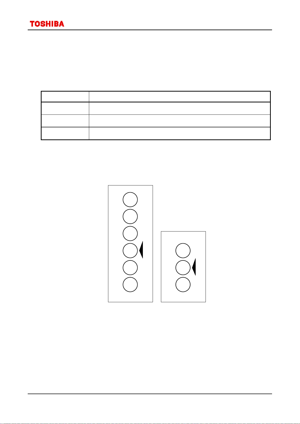
Moisture indicators can detect the approximate humidity level at a standard temperature of
25°C. 6-point indicators and 3-point indicators are currently in use, but eventually all
indicators will be 3-point indicators.
HUMIDITY INDICATOR
60%
50%
40%
30%
20%
10%
READ AT LAVENDER
BETWEEN PINK & BLUE
(a) 6-point indicator (b) 3-point indicator
DANGER IF PINK
HUMIDITY INDICATOR
CHANGE DESICCANT
READ AT LAVENDER
BETWEEN PINK & BLUE
40
30
20
Figure 1 Humidity indicator
DANGER IF PINK
10

3 General Safety Precautions and Usage Considerations
3.3 Design
Care must be exercised in the design of electronic equipment to achieve th e desired reliability. It
is important not only to adhere to specifications concerning absolute maximum ratings and
recommended operating conditions, it is also important to consider the overall environment in
which equipment will be used, including factors such as the ambient temperature, transient
noise and voltage and current surges, as well as mounting conditions which affect device
reliability. This section describes some general precautions which you should observe when
designing circuits and when mounting devices on printed circuit boards.
For more detailed information about each product family, refer to the relevant individual
technical datasheets available from Toshiba.
3.3.1 Absolute maximum ratings
Do not use devices under conditions in whic h their absolute maximum
ratings (e.g. current, voltage, power dissipation or temperature) will be
exceeded. A device may break down or its performance may be degraded,
causing it to catch fire or explode resulting in injury to the user.
The absolute maximum ratings are rated values which must not be
exceeded during operation, even for an instant. Although absolute
maximum ratings differ from product to product, they essentially
concern the voltage and current at each pin, the allowable power
dissipation, and the junction and storage temperatures.
If the voltage or current on any pin exceeds the absolute maximum
rating, the device’s internal circuitry can become degraded. In the worst case, heat generated in
internal circuitry can fuse wiring or cause the semiconductor chip to break down.
If storage or operating temperat ures exceed rated values, the package seal can deteriorate or the
wires can become disconnected due to the differences between the thermal expansion coefficients
of the materials from which the device is constructed.
3.3.2 Recommended operating conditions
The recommended operating conditions for each device are those necessary to guarantee that the
device will operate as specified in the datasheet.
If greater reliability is required, derate the device’s absolute maximum ratings for voltage,
current, power and temperature before using it.
3.3.3 Derating
When incorporating a device into your design, reduce its rated absolute maximum voltage,
current, power dissipation and operating temperature in order to ensure high reliability.
Since derating differs from application to application, refer to the technical datasheets available
for the various devices used in your design.
3.3.4 Unused pins
If unused pins are left open, some devices ca n exhibit input instability problems, resulting in
malfunctions such as abrupt increase in current flow. Similarly, if the unused output pins on a
device are connected to the power supply pin, the ground pin or to other output pins, the IC may
malfunction or break down.
Since the details regarding the handling of unused pins differ from device to device and from pin
11

3 General Safety Precautions and Usage Considerations
to pin, please follow the instructions given in the relevant individual datasheets or databook.
CMOS logic IC inputs, for example, have extremely high impedance. If an input pin is left open,
it can easily pick up extraneous noise and become unstable. In this case, if the input voltage level
reaches an intermediate level, it is possible that both the P-channel and N-channel transistors
will be turned on, allowing unwanted supply current to flow. Therefore, ensure that the unused
input pins of a device are connected to the power supply (Vcc) pin or ground (GND) pin of the
same device. For details of what to do with the pins of heat sinks, refer to the relevant technical
datasheet and databook.
3.3.5 Latch-up
Latch-up is an abnormal condition inherent in CMOS devices, in which Vcc gets shorted to
ground. This happens when a parasitic PN-PN junction (thyristor structure) internal to the
CMOS chip is turned on, causing a large current of the order of several hundred mA or more to
flow between Vcc and GND, eventually causing the device to break down.
Latch-up occurs when the input or output voltage exceeds the rated value, causing a large
current to flow in the internal chip, or when the voltage on the Vcc (Vdd) pin exceeds its rated
value, forcing the internal chip into a breakdown condition. Once the chip falls into the latch-up
state, even though the excess voltage may have been applied only for an instant, the large
current continues to flow between Vcc (Vdd) and GND (Vss). This causes the device to heat up
and, in extreme cases, to emit gas fumes as well. To avoid this problem, observe the following
precautions:
(1) Do not allow voltage levels on the input and output pins either to rise above Vcc (Vdd) or to
fall below GND (Vss). Also, follow any prescribed power-on sequence, so that power is applied
gradually or in steps rather than abruptly.
(2) Do not allow any abnormal noise signals to be applied to the device.
(3) Set the voltage levels of unused input pins to Vcc (Vdd) or GND (Vss).
(4) Do not connect output pins to one another.
3.3.6 Input/Output protection
Wired-AND configurations, in which outputs are connected together, cannot be used, since this
short-circuits the outputs. Outputs should, of course, never be connected to Vcc (Vdd) or GND
(Vss).
Furthermore, ICs with tri-state outputs can undergo performance degradation if a shorted output
current is allowed to flow for an extended period of time. Therefore, when designing circuits,
make sure that tri-state outputs will not be enabled simultaneously.
3.3.7 Load capacitance
Some devices display increased delay times if the load capacitance is large. Also, large charging
and discharging currents will flow in the device, causing noise. Furthermore, since outputs are
shorted for a relatively long time, wiring can become fused.
Consult the technical information for the device being used to determine the recommended load
capacitance.
12

3 General Safety Precautions and Usage Considerations
3.3.8 Thermal design
The failure rate of semiconductor devices is greatly increased as operating temperatures
increase. As shown in Figure 2, the internal thermal stress on a device is the sum of the ambient
temperature and the temperature rise due to power dissipation in t he device. Therefore, to
achieve optimum reliability, observe the following precautions concerning thermal design:
(1) Keep the ambient temperature (Ta) as low as possible.
(2) If the device’s dynamic power dissipation is relatively large, select the most appropriate
circuit board material, and consider the use of heat sinks or of forced air cooling. Such
measures will help lower the thermal resistance of the package.
(3) Derate the device’s absolute maximum ratings to minimize thermal stress from power
dissipation.
θja = θjc + θca
θja = (Tj–Ta) / P
θjc = (Tj–Tc) / P
θca = (Tc–Ta) / P
in which θja = thermal resistance between junction and surrounding air (°C/W)
θjc = thermal resistance between junction and package surface, or internal thermal
resistance (°C/W)
θca = thermal resistance between package surface and surrounding air, or external
thermal resistance (°C/W)
Tj = junction temperature or chip temperature (°C)
Tc = package surface temperature or case temperature (°C)
Ta = ambient temperature (°C)
P = power dissipation (W)
Ta
θca
Tc
θjc
Tj
Figure 2 Thermal resistance of package
3.3.9 Interfacing
When connecting inputs and out puts between devices, make sure input voltage (VIL/VIH) and
output voltage (V
connecting devices operating at different supply voltages, such as in a dual-power-supply system,
be aware that erroneous power-on and power-off sequences can result in device breakdown. For
details of how to interface particular devices, consult the relevant technical datasheets and
databooks. If you have any questions or doubts about interfacing, contact your nearest Toshiba
office or distributor.
OL/VOH
) levels are matched. Otherwi se, the devices may malfunction. When
13

3 General Safety Precautions and Usage Considerations
3.3.10 Decoupling
Spike currents generated during switching can cause Vcc (Vdd) and GND (Vss) voltage levels to
fluctuate, causing ringing in the output waveform or a delay in response speed. (The power
supply and GND wiring impedance is normally 5 0 Ω to 100 Ω.) For this reason, the impedance of
power supply lines with respect to high frequencies must be kept low. This can be accomplished
by using thick and short wiring for the Vcc (Vdd) and GND (Vss) lines and by installing
decoupling capacitors (of approximately 0.01 µF to 1 µF capacitance) as high-frequency filters
between Vcc (Vdd) and GND (Vss) at strategic locations on the printed circuit board.
For low-frequency filtering, it is a good idea to install a 10- to 100-µF capacitor on the printed
circuit board (one capacitor will suffice). If the capacitance is excessively large, however, (e.g.
several thousand µF) latch-up can be a problem. Be sure to choose an appropriate capacitance
value.
An important point about wiring is that, in the case of high-speed logic ICs, noise is caused
mainly by reflection and crossta lk, or by the power supply impedance. Reflect ions cause
increased signal delay, ringing, overshoot and undershoot, thereby reducing the device’s safety
margins with respect to noise. To prevent reflections, reduce the wiring length by increasing the
device mounting density so as to lower the inductance (L) and capacitance (C) in the wiring.
Extreme care must be taken, however, when taking this corrective measure, since it tends to
cause crosstalk between the wires. In practice, there must be a trade-off between these two
factors.
3.3.11 External noise
Printed circuit boards with long I/O or signal pattern lines
are vulnerable to induced noise or surges from outside
sources. Consequently, malfunctions or breakdowns can
result from overcurrent or overvoltage, depending on the
types of device used. To protect against noise, lower the
impedance of the pattern line or insert a noise-canceling
circuit. Protective measures must also be taken against
surges.
For details of the appropriate protective measures for a particular device, consult the relevant
databook.
Input/Output
Signals
3.3.12 Electromagnetic interference
Widespread use of electrical and electronic equipment in recent years has brought with it radio
and TV reception problems due to electromagnetic interference. To use the radio spectrum
effectively and to maintain radio communications quality, each country has formulated
regulations limiting the amount of electromagnetic interference which can be generated by
individual products.
Electromagnetic interference includes conduction noise propagated through power supply and
telephone lines, and noise from direct electromagnetic waves radiated by equipment. Different
measurement methods and corrective measures are used to assess and counteract each specific
type of noise.
Difficulties in controlli n g electromagnetic interference derive from the fact that there is no
method available whic h allows designers to calculate, at the design stage, the strength of the
electromagnetic waves which will emanate from each component in a piece of equipment. For this
reason, it is only after the prototype equipment has been completed that the designer can take
measurements using a dedicated i n strument to determine the strength of electromagnetic
interference waves. Yet it is possible during system design to incorporate some measures for the
14

3 General Safety Precautions and Usage Considerations
prevention of electromagnetic interference, which can facilitate taking corrective measures once
the design has been completed. These include installing shields and noise filters, and increasing
the thickness of the power supply wiring patterns on the printed circuit board. One effective
method, for example, is to devise several shielding options during design, and then select the
most suitable shielding method based on the results of measurements taken after the prototype
has been completed.
3.3.13 Peripheral circuits
In most cases semiconductor devices are used with peripheral circuits and components. The input
and output signal voltages and currents in these circuits must be chosen to match the
semiconductor device’s specifications. The following factors must be taken into account.
(1) Inappropriate voltages or currents applied to a device’s input pins may cause it to operate
erratically. Some devices contain pull-up or pull-down resistors. When designing your
system, remember to take the effect of this on the voltage and current levels into account.
(2) The output pins on a device have a predetermined external circuit drive capability. If this
drive capability is greater than that required, either incorporate a compensating circuit into
your design or carefully select suitable components for use in external circuits.
3.3.14 Safety standards
Each country has safety standards which must be observed. These safety standards include
requirements for quality assurance systems and design of device insulation. Such requirements
must be fully taken into account to ensure that your design conforms to the applicable safety
standards.
3.3.15 Other precautions
(1) When designing a system, be sure to incorporate fail-safe and other appropriate measures
according to the intended purpose of your system. Also, be sure to debug your system under
actual board-mounted conditions.
(2) If a plastic-package device is placed in a strong electric field, surface leakage may occur due
to the charge-up phenomenon, resulting in device malfunction. In such cases take
appropriate measures to prevent this problem, for example by protecting the package surface
with a conductive shield.
(3) With some microcomputers and MOS memory devices, caution is required when powering on
or resetting the device. To ensure that your design does not violate device specifications,
consult the relevant databook for each constituent device.
(4) Ensure that no conductive material or object (such as a metal pin) can drop onto and short
the leads of a device mounted on a printed circuit board.
3.4 Inspection, Testing and Evaluation
3.4.1 Grounding
Ground all measuring instruments, jigs, tools and soldering irons to earth.
Electrical leakage may cause a device to break down or may result in electric
shock.
15

3 General Safety Precautions and Usage Considerations
3.4.2 Inspection Sequence
! Do not insert devices in the wrong orientation. Make sure that the positive
and negative electrodes of the power supply are correctly connected.
Otherwise, the rated maximum current or maximum power dissipation
may be exceeded and the device may brea k down or undergo performance
degradation, causing it to catch fire or explode, resulting in injury to the
user.
" When conducting any kind of evaluat ion, inspection or testing using A C
power with a peak voltage of 42.4 V or DC power exceeding 60 V, be sure
to connect the electrodes or probes of the testing equipment to the device
under test before powering it on. Connecting the electrodes or probes of
testing equipment to a device while it is powered on may result in electric
shock, causing injury.
(1) Apply voltage to the test jig only after inserting the device securely into it. When applying or
removing power, observe the relevant precautions, if any.
(2) Make sure that the voltage applied to the device is off before removing the device from the
test jig. Otherwise, the device may undergo performance degradation or be destroyed.
(3) Make sure that no surge voltages from the measuring equipment are applied to the device.
(4) The chips housed in tape carrier packages (TCPs) are bare chips and are th erefore exposed.
During inspection take care not to crack the chip or cause any flaws in it.
Electrical contact may also cause a chip to become faulty. Therefore make sure that nothing
comes into electrical contact with the chip.
3.5 Mounting
There are essentially two main types of semiconductor device package: lead insertion and surface
mount. During mounting on printed circuit boards, devices can become contaminated by flux or
damaged by thermal stress from the soldering process. With surface-mount devices in particular,
the most significant problem is thermal stress from solder reflow, when the entire package is
subjected to heat. This section describes a recommended temperature profile for each mounting
method, as well as general precautions which you should take when mounting devices on printed
circuit boards. Note, however, that even for devices with the same package type, the appropriate
mounting method varies according to the size of the chip and the size and shape of the lead
frame. Therefore, please consult the relevant technical datasheet and databook.
3.5.1 Lead forming
! Always wear protective glasses when cutting the leads of a device with
clippers or a similar tool. If you do not, small bits of metal flying off the cut
ends may damage your eyes.
" Do not touch the tips of device leads. Because some types of device have
leads with pointed tips, you may prick your finger.
Semiconductor devices must undergo a process in which the leads are cut and formed before the
devices can be mounted on a printed circuit board. If undue stress is applied to the interior of a
device during this process, mechanical breakdown or performance degradation can result. This is
attributable primarily to differences between the stress on the device’s external leads and the
stress on the internal leads. If the relative difference is great enough, the device’s internal leads,
adhesive properties or sealant can be damaged. Observe these precautions during the leadforming process (this does not apply to surface-mount devices):
16

3 General Safety Precautions and Usage Considerations
(1) Lead insertion hole intervals on the printed circuit board should match the lead pitch of the
device precisely.
(2) If lead insertion hole intervals on the printed circuit board do not precisely match the lead
pitch of the device, do not attempt to forcibly insert devices by pressing on them or by pulling
on their leads.
(3) For the minimum clearance specification between a device and a
printed circuit board, refer to the relevant device’s datasheet and
databook. If necessary, achieve the required clearance by forming
the device’s leads appropri ately. Do not use the spacers which are
used to raise devices above the surface of the printed circuit board
during soldering to achieve clearance. These spacers normally
continue to expand due to heat, even after the solder has begun to solidify; this applies
severe stress to the device.
(4) Observe the following precautions when forming the leads of a device prior to mounting.
•
Use a tool or jig to secure the lead at its base (where the lead meets the device package) while
bending so as to avoid mechanical stress to the device. Also avoid bending or stretching device
leads repeatedly.
•
Be careful not to damage the lead during lead forming.
•
Follow any other precautions described in the individual datasheets and databooks for each
device and package type.
3.5.2 Socket mounting
(1) When socket mounting devices on a printed circuit board, use sockets which match the
inserted device’s package.
(2) Use sockets whose contacts have the appropriate contact pressure. If the contact pressure is
insufficient, the socket may not make a perfect contact when the device is repeatedly
inserted and removed; if the pressure is excessively high, the device leads may be bent or
damaged when they are inserted into or removed from the socket.
(3) When soldering sockets to the printed circuit board, use sockets whose construction prevents
flux from penetrating into the contacts or which allows flux to be completely cleaned off.
(4) Make sure the coating agent applied to the printed circuit board for moisture-proofing
purposes does not stick to the socket contacts.
(5) If the device leads are severely bent by a socket as it is inserted or removed and you wish to
repair the leads so as to continue using the device, make sure that this lead correction is only
performed once. Do not use devices whose leads have been corrected more than once.
(6) If the printed circuit board with the devices mounted on it will be subjected to vibration from
external sources, use sockets which have a strong contact pressure so as to prevent the
sockets and devices from vibrating relative to one another.
3.5.3 Soldering temperature profile
The soldering temperature and heating time vary from device to device. Therefore, when
specifying the mounting conditi ons, refer to the individual datasheets and databooks for the
devices used.
17

3 General Safety Precautions and Usage Considerations
(1) Using a soldering iron
Complete soldering within ten seconds for lead temperatures of up to 260°C, or within three
seconds for lead temperatures of up to 350°C.
(2) Using medium infrared ray reflow
•
Heating top and bottom with long or medium infrared rays is recommended (see Figure 3).
Medium infrared ray heater
(reflow)
Product flow
Long infrared ray heater (preheating)
Figure 3 Heating top and bottom with long or medium infrared rays
•
Complete the infrared ray reflow process within 30 seconds at a package surface temperature
of between 210°C and 240°C.
•
Refer to Figure 4 for an example of a good temperature profile for infrared or hot air reflow.
(°C)
240
210
160
140
Package surface temperature
60-120
seconds
Time (in seconds)
30
seconds
or less
Figure 4 Sample temperature profile for infrared or hot air reflow
(3) Using hot air reflow
•
Complete hot air reflow within 30 seconds at a package surface temperature of between 210°C
and 240°C.
•
For an example of a recommended temperature profile, refer to Figure 4 above.
(4) Using solder flow
•
Apply preheating for 60 to 120 seconds at a temperature of 150°C.
•
For lead insertion-type packages, complete solder flow within 10 seconds with the
temperature at the stopper (or, if there is no stopper, at a location more than 1.5 mm from
the body) which does not exceed 260°C.
•
For surface-mount packages, complete soldering within 5 seconds at a temperature of 250°C or
18

3 General Safety Precautions and Usage Considerations
less in order to prevent thermal stress in the device.
•
Figure 5 shows an example of a recommended temperature profile for surface-mount packages
using solder flow.
(°C)
250
160
140
Package surface temperature
60-120 seconds
Time (in seconds)
Figure 5 Sample temperature profile for solder flow
5 seconds
or less
3.5.4 Flux cleaning and ultrasonic cleaning
(1) When cleaning circuit boards to remove flux, make sure that no residual reactive ions such
as Na or Cl remain. Note that organic solvents react with water to generate hydrogen
chloride and other corrosive gases which can degrade device performance.
(2) Washing devices with water will not cause any problems. However, make sure that no
reactive ions such as sodium and chlorine are left as a residue. Also, be sure to dry devices
sufficiently after washing.
(3) Do not rub device markings with a brush or with your hand during cleaning or while the
devices are still wet from the cleaning agent. Doing so can rub off the markings.
(4) The dip cleaning, shower cleaning and steam cleaning processes all involve the chemical
action of a solvent. Use only recommended solvents for these cleaning methods. When
immersing devices in a solvent or steam bath, make sure that the temperature of the liquid
is 50°C or below, and th at the circuit board is removed from the bath within one minute.
(5) Ultrasonic cleaning should not be used with hermetically-sealed ceramic packages such as a
leadless chip carrier (LCC), pin grid array (PGA) or charge-coupled device (CCD), because
the bonding wires can become disconnected due to resonance during the cleaning process.
Even if a device package allows ultrasonic cleaning, limit the duration of ultrasonic cleaning
to as short a time as possible, since long hours of ultrasonic cleaning degrade the adhesion
between the mold resin and the frame material. The following ultrasonic cleaning conditions
are recommended:
Frequency: 27 kHz ∼ 29 kHz
Ultrasonic output power: 300 W or less (0.25 W/cm
2
or less)
Cleaning time: 30 seconds or less
Suspend the circuit board in the solvent bath during ultrasonic cleaning i n such a way that
the ultrasonic vibrator does not come into direct contact with the circuit board or the device.
19

3 General Safety Precautions and Usage Considerations
3.5.5 No cleaning
If analog devices or high-speed devices are used without being cleaned, flux residues may cause
minute amounts of leakage between pins. Similarly, dew condensation, which occurs in
environments containing residual chlorine when power to the device is on, may cause betweenlead leakage or migration. Therefore, Toshiba recommends that these devices be cleaned.
However, if the flux used contains only a small amount of halogen (0.05W% or less), the devices
may be used without cleaning without any problems.
3.5.6 Mounting tape carrier packages (TCPs)
(1) When tape carrier packages (TCPs ) are mounted, measures must be taken to prevent
electrostatic breakdown of the devices.
(2) If devices are being picked up from tape, or outer lead bonding (OLB) mounting is being
carried out, consult the manufacturer of the insertion machine which is being used, in order
to establish the optimum mounting conditions in advance and to avoid any possible hazards.
(3) The base film, which is made of polyimide, is hard and thin. Be careful not to cut or scratch
your hands or any objects while handling the tape.
(4) When punching tape, try not to scatter broken pieces of tape too much.
(5) Treat the extra film, reels and spacers left after punching as indust rial waste, taking care
not to destroy or pollute the environment.
(6) Chips housed in tape carrier packages (TCPs) are bare chips and therefore have their reverse
side exposed. To ensure that the chip will not be cracked during mounting, ensure that no
mechanical shock is applied to the reverse side of the chip. Electrical contact may also cause
a chip to fail. Therefore, when mounting devices, make sure that nothing comes into
electrical contact with the reverse side of the chip.
If your design requires connecting the reverse side of the chip to the circuit board, please
consult Toshiba or a Toshiba distributor beforehand.
3.5.7 Mounting chips
Devices delivered in chip form tend to degrade or break under external forces much more easily
than plastic-packaged devices. Therefore, caution is required when handling this type of device.
(1) Mount devices in a properly prepared environment so that chip surfaces will not be exposed
to polluted ambient air or other polluted substances.
(2) When handling chips, be careful not to expose them to static electricity.
In particular, measures must be taken to prevent static damage during the mounting of
chips. With this in mind, Toshiba recommend mounting all peripheral parts first and then
mounting chips last (after all other components have been mounted).
(3) Make sure that PCBs (or any other kind of circuit board) on which chips are being mounted
do not have any chemical residues on them (such as the chemicals which were used for
etching the PCBs).
(4) When mounting chips on a board, use the method of assembly that is most suitable for
maintaining the appropriate electrical, thermal and mechanical properties of the
semiconductor devices used.
* For details of devices in chip form, refer to the relevant device’s individual datasheets.
20

3 General Safety Precautions and Usage Considerations
3.5.8 Circuit board coating
When devices are to be used in equipment requiring a high degree of reliability or in extreme
environments (where moisture, corrosive gas or dust is present), circuit boards may be coated for
protection. However, before doing so, you must carefully consider the possible stress and
contamination effects that may result and then choose the coating resin which results in the
minimum level of stress to the device.
3.5.9 Heat sinks
(1) When attaching a heat sink to a device, be careful not to apply excessive force to the device in
the process.
(2) When attaching a device to a heat sink by fixing it at two or more locations , evenly tighten
all the screws in stages (i.e. do not fully tighten one screw while the rest are still only l oosely
tightened). Finally, fully tighten all the screws up to the specified torque.
(3) Drill holes for screws in the heat sink exactly as specified. Smooth the
surface by removing burrs and protrusions or indentations which might
interfere with the installation of any part of the device.
(4) A coating of silicone compound can be applied between the heat sink and
the device to improve heat conductivity. Be sure to apply the coating
thinly and evenly; do not use too much. Also, be sure to use a non-volatile
compound, as volatile compounds can crack after a time, causing the
heat radiation properties of the heat sink to deteriorate.
(5) If the device is housed in a plastic package, use caution when selecting the type of silicone
compound to be applied between the heat sink and the device. With some types, the base oil
separates and penetrates the plastic package, significantly reducing the useful life of the
device.
Two recommended silicone compounds in which base oil separation is not a problem are
YG6260 from Toshiba Silicone.
(6) Heat-sink-equipped devices can become very hot during operation. Do not touch them, or you
may sustain a burn.
3.5.10 Tightening torque
(1) Make sure the screws are tightened with fastening torques not exceeding the torque values
stipulated in individual datasheets and databooks for the devices used.
(2) Do not allow a power screwdriver (electrical or air-driven) to touch devices.
3.5.11 Repeated device mounting and usage
Do not remount or re-use devices which fall into the categories listed below; these devices may
cause significant problems relating to performance and reliability.
(1) Devices which have been removed from the boar d after soldering
(2) Devices which have been inserted in the wrong orientation or which have had reverse
current applied
(3) Devices which have undergone lead forming more than once
21

3 General Safety Precautions and Usage Considerations
3.6 Protecting Devices in the Field
3.6.1 Temperature
Semiconductor devices are generally more sensitive to temperature than are other electronic
components. The various elect rical characteristics of a semiconductor device are dependent on the
ambient temperature at which the device is used. It is therefore necessary to understand the
temperature characteristics of a device and to incorporate device derating into circuit design.
Note also that if a device is used above its maximum temperature rating, device deterioration is
more rapid and it will reach the end of its usable life sooner than expected.
3.6.2 Humidity
Resin-molded devices are sometimes improperly sealed. When t hese devices are used for an
extended period of time in a high-humidity environment, moisture can penetrate into the device
and cause chip degradation or malfunction. Furthermore, when devices are mounted on a regular
printed circuit board, the impedance between wiring components can decrease under highhumidity conditions. In systems which require a high signal-source impedance, circuit board
leakage or leakage between device lead pins can cause malfunctions. The application of a
moisture-proof treatment to the device surface should be considered in this case. On the other
hand, operation under low-humidity conditions can damage a device due to the occurrence of
electrostatic discharge. Unless damp-proofing measures have been specifically taken, use devices
only in environments with appropriate ambient moisture levels (i.e. within a relative humidity
range of 40% to 60%).
3.6.3 Corrosive gases
Corrosive gases can cause chemical reacti ons in devices, degrading device characteristics.
For example, sulphur-bearing corrosive gases emanating from rubber placed near a device
(accompanied by condensation under high-humidity conditions) can corrode a device’s leads. The
resulting chemical reaction between leads forms foreign particles which can cause electrical
leakage.
3.6.4 Radioactive and cosmic rays
Most industrial and consumer semiconductor devices are not designed with protection against
radioactive and cosmic rays. Devices used in aerospace equipment or in radioactive environments
must therefore be shielded.
3.6.5 Strong electrical and magnetic fields
Devices exposed to strong magnetic fields can undergo a polarization phenomenon in their plastic
material, or within the chip, which gives rise to abnormal symptoms such as impedance changes
or increased leakage current. Failures have been reported in LSIs mounted near malfunctioning
deflection yokes in TV sets. In such cases the device’s installation location must be changed or
the device must be shielded against the electrical or magnetic field. Shielding against magnetism
is especially necessary for devices used in an alternating magnetic field because of the
electromotive forces generated in this type of environment.
22

3 General Safety Precautions and Usage Considerations
3.6.6 Interference from light (ultraviolet rays, sunlight, fluorescent lamps and incandescent lamps)
Light striking a semiconductor device generates electromotive force due to photoelectric effects.
In some cases the device can malfunction. This is especially true for devices in which the internal
chip is exposed. When designing circuits, make sure that devices are protected against incident
light from external sources. This problem is not limited to optical semiconductors and EPROMs.
All types of device can be affected by light.
3.6.7 Dust and oil
Just like corrosive gases, dust and oil can cause chemical reactions in devices, which will
adversely affect a device’s electrical characteristics. To avoid this problem, do not use devices in
dusty or oily environments. This is especially important for optical devices because dust and oil
can affect a device’s optical characteristics as well as its physical integrity and the electrical
performance factors mentioned above.
3.6.8 Fire
Semiconductor devices are combustible; they can emit smoke and catch fire if heated sufficiently.
When this happens, some devices may generate poisonous gases. Devices should therefore never
be used in close proximity to an open flame or a heat-generating body, or near flammable or
combustible materials.
3.7 Disposal of Devices and Packing Materials
When discarding unused devices and packing materials, follow all procedures specified by local
regulations in order to protect the environment against contamination.
23

4 Precautions and Usage Considerations Specific to Each Product Group
4. Precautions and Usage Considerations Specific to Each
Product Group
This section describes matters specific to each product group which need to be taken into
consideration when using devices. If the same item is described in Sections 3 and 4, the
description in Section 4 takes precedence.
4.1 Microcontrollers
4.1.1 Design
(1) Using resonators which are not specifically recommended for use
Resonators recommended for use with Toshiba products in microcontroller oscillator applications
are listed in Toshiba databooks along with information about oscillation conditions. If you use a
resonator not included in this list, please consult Toshiba or the resonator manufacturer
concerning the suitability of the device for your application.
(2) Undefined func tions
In some microcontrollers certain instruction code values do not constitute valid processor
instructions. Also, it is possible that the values of bits in registers will become undefined. Take
care in your applications not to use invalid instructions or to let register bit values become
undefined.
(3) Scratc h and punct ure wounds by the point of a probe
The tips of probes and adaptors used in development tools are individually designed to be
compatible with particular devices. Probes for some devices have sharp points. When you handle
them bare-handed, take care not to suffer a scratch or puncture wound.
24

4 Precautions and Usage Considerations Specific to Each Product Group
4.1.2 Reliability predictions for microcontroller devices
For microcontroller devices, the following junction temperature range is used for reliability
predictions:
Tj = 0°C ∼ 85°C
An estimation of the chip junction temperature, Tj, can be obtained from the equation:
Tj = Ta + Q וja
where:
Ta = ambient temperature (°C)
The assumption is that the ambient temperature is not affected by any heat
transfers from the device.
Q = chip’s average power dissipation (W)
•ja = package thermal resistance (°C/W)
Note 1: If you use a microcontroller device outside the 0 to 85°C range for long periods of time, contact
your nearest Toshiba office or authorized Toshiba dealer.
Note 2: For the •ja value, contact your nearest Toshiba office or authorized Toshiba dealer.
25

4 Precautions and Usage Considerations Specific to Each Product Group
26

Part 1 TMP1940


TMP1940CYAF
32-Bit RISC Microprocessor TX19 Family
TMP1940CYAF
1. Features
The TX19 is a family of high-performance 32-bit microprocessors that offers the speed of a 32-bit RISC
solution with the added advantage of a significantly reduced code size of a 16-bit architecture. The instruction
set of the TX19 includes as a subset the 32-bit instructions of the TX39, which is based on the MIPS R3000A
architecture. Additionally, the TX19 supports the MIPS16 Application-Specific Extensions (ASE) for improved
code density.
The TMP1940 is built on a TX19 core processor and a selection of intelligent peripherals. The TMP1 940 is
suitable for low-voltage, low-power applications.
Features of the TMP1940 include the following:
(1) TX19 core processor
1) Two instruction set architecture (ISA) modes: 16-bit ISA for code density and 32-bit ISA for speed
• The 16-bit ISA is object-code compatible with the code-efficient MIPS16 ASE.
• The 32-bit ISA is object-code compatible with the high-performance TX39 family.
TM
2) Combines high performance with low power consumption.
— High performance
• Single clock cycle execution for most instructions
• 3-operand computational instructions for high instruction throughput
• 5-stage pipeline
• On-chip high-speed memory
• DSP function: Executes 32-bit x 32-bit multiplier operations with a 64-bit accumulation in a single
clock cycle.
— Low power consumption
• Optimized
• Programmable
design using a low-power cell library
standby modes in which processor clocks are stopped
3) Fast interrupt response suitable for real-time control
• Distinct starting locations for each interrupt service routine
• Automatically generated vectors for each interrupt source
• Automatic updates of the interrupt mask level
980508EBA1
• TOSHIBA continually is working to improve the quality and the reliability of its products. Nevertheless, semiconductor devic es in
general can malfunction or fail due to their inherent electrical sensitivity and vulnerability to physical stress. It is the responsibility
of the buyer, when utilizing TOSHIBA products, to observe standards of safety, and to avoid situations in which a malfunction or
failure of a TOSHIBA product could cause loss of human life, bodily injury or damage to property. In developing your designs,
please ensure that TOSHIBA products are used within specified operating ranges as set forth in the most recent products
specifications. Also, please keep in mind the precautions and conditions set forth in the TOSHIBA Semiconductor Reliability
Handbook.
• The products described i n this document are subject to foreign exchange and foreign trade laws.
• The information contained herein is presented only as a guide for the applications of our products. No responsibility is assumed
by TOSHIBA CORPORATION for any infringements of intellectual property or other rights of the third parties which may result
from its use. No license is granted by implication or otherwise under any intellectual property or other rights of TOSHIBA
CORPORATION or others.
Purchase of TOSHIBA I2C components conveys a license under the Philips I2C Patent Rights to use these
components in an I
by Philips.
2
C system, provided that the system conforms to the I2C Standard Specification as defined
TMP1940CYAF-1

TMP1940CYAF
(2) 10-Kbyte on-chip RAM
256-Kbyte on-chip ROM
(The TMP1940FDBF has 512-Kbyte FE
(3) External memory expansion
• 16-Mbyte off-chip address space for code and data
• External bus interface with dynamic bus sizing for 8-bit and 16-bit data ports
(4) 4-channel DMA cont roller
• Interrupt- or software-triggered
(5) 4-channel 8-bit timer
(6) 4-channel 16-bit timer
(7) 1-channel real-time counter (RTC)
(8) 4-channel general-purpose serial interface
Two channels support both UART and synchronous transfer modes and the other two channels are solely
for UART.
2
PROM and 16-Kbyte RAM.)
(9) 1-channel serial bus interface
2
Either I
C bus mode or clock-synchronous mode can be selected.
(10) 8-channel 10-bit A/D converter (with internal sample/hold)
Conversion time: 10.75 µs @32 MHz
(11) Watchdog timer
(12) 4-channel chip select/wait controller
(13) Interrupt sources
• 4 CPU interrupts: software interrupt instruction
• 32 internal interrupts: 7 priority levels, with the exception of the watchdog timer interrupt
• 11 external interrupts: 7 priority levels, with the exception of the NMI interrupt
(14) 77-pin input/output ports
(15) Four standby modes
• IDLE (HALT, DOZE), SLEEP, STOP
(16) Dual clocks
• Clock for low-power operation: Low-speed clock (32.768 kHz)
• RTC clock: Low-speed clock (32.768 kHz)
(17) Clock generato r
• On-chip PLL (x4)
• Clock gear: Divides the operating speed of the CPU by 1/2, 1/4 or 1/8
(18) Little-endian
Higher address 31 24 23 16 15 8 7 0 Word address
11 10 9 8 8
7654 4
Lower address 3 2 1 0 0
• Byte 0 is the lowest-order byte (bits 7-0).
• The address of a word data item is the address of its lowest-order byte (byte 0).
TMP1940CYAF-2

(19) Operating voltage range: 2.7 to 3.6 V
(20) Operating fre q ue ncy
• 32 MHz (Vcc ≥ 3.0 V)
• 26 MHz (Vcc ≥ 2.7 V)
(21) Package
• 100-pin QFP (14 x 14 x 1.4 (t) mm, 0.5-mm pitch)
TMP1940CYAF
TMP1940CYAF-3

TX19 Processor Core
)
)
)
TX19 CPU
MAC
TMP1940CYAF
NMI
INT0 (P77)
INT1-4 (PA0-3)
INT5-A,
(P74-5, P80-1, P83-4)
(P53)
ADTRG
(P50−P57)
AN0−AN7
AVCC, AVSS
VREFH, VREFL
TXD0 (P90)
RXD0 (P91)
(P92)
SCLK0/
CTS0
TXD1 (P93)
RXD1 (P94)
(P95)
SCLK1/
CTS1
SCK (PA5)
SO/SDA (PA6)
SI/SCL (PA7)
TA0IN (P70)
TA1OUT (P71)
256-Kbyte ROM
DMAC (4ch)
INTC
EBIF
10-Bit
ADC
SIO0
SIO1
Serial
Bus I/F
(SBI)
8-Bit TMRA0/1
I/O Bus I/F
10-Kbyte RAM
G-Bus
CG
PORT0
PORT1
PORT2
PORT3
PORT4
( ): Initial pin function
after reset
X1
X2
XT1 (P96)
XT2 (P97)
SCOUT (P44)
PLLOFF
RESET
(P00-P07)
AD0-AD7
(P10-P17)
AD8/A8-AD15/A15
(P20-P27)
A0/A16-A7/A23
(P30)
RD
(P31)
WR
(P32)
HWR
(P33)
WAIT
W/R
(P34)
(P35)
(P36)
BUSRQ
BUSAK
P37
(P40-P43)
CS0-CS3
TA2IN (P72)
TA3OUT (P73)
TB0IN0/INT5 (P74)
TB0IN1/INT6 (P75
TB0OUT (P76)
TB1IN0/INT7 (P80)
TB1IN1/INT8 (P81
TB1OUT (P82)
TB2IN0/INT9 (P83
TB2IN1/INTA (P84)
TB2OUT (P85)
TB3OUT (P86)
8-Bit TMRA2/3
16-Bit TMRB0
16-Bit TMRB1
16-Bit TMRB2
16-Bit TMRB3
WDT
Real-Time
Counter (RTC)
SIO3
SIO4
BW0/1
INTLV (P86)
TXD3 (P70)
RXD3 (P71)
TXD4 (P72)
RXD4 (P73)
Figure 1.1 TMP1940CYAF Block Diagram
TMP1940CYAF-4

2. Signal Descriptions
This section contains pin assignments for the TMP1940CYAF as well as brief descriptions of the
TMP1940CYAF input and output signals.
2.1 Pin Assignment
The following illustrates the TMP1940CYAF pin assignment.
TMP1940CYAF
DVSS 89
P50/AN0 90
P51/AN1 91
P52/AN2 92
P53/AN3/ADTRG 93
P54/AN4 94
P55/AN5 95
P56/AN6 96
P57/AN7 97
VREFH 98
VREFL 99
AVSS
AVCC 1
P70/TA0IN/TXD3 2
P71/TA1OUT/RXD3 3
P72/TA2IN/TXD4 4
P73/TA3OUT/RXD4 5
P74/TB0IN0/INT5 6
P75/TB0IN1/INT6 7
P76/TB0OUT 8
P77/INT0 9
P80/TB1IN0/INT7 10
P81/TB1IN1/INT8 11
P82/TB1OUT 12
P83/TB2IN0/INT9 13
P84/TB2IN1/INTA 14
P85/TB2OUT 15
P86/TB3OUT/INTLV 16
P87 17
P90/TXD0 18
P91/RXD0 19
P92/SCLK0/CTS0 20
P93/TXD1 21
P94/RXD1 22
P95/SCLK1/CTS1 23
BW0 24
CVCC 25
100
88 P44/SCOUT
87 DVCC
86 P43/CS3
85 P42/CS2
84 P41/CS1
83 P40/CS0
82 P37
81 P36/R/W
80 P35/BUSAK
79 P34/BUSRQ
78 P33/WAIT
77 P32/HWR
76 P31/WR
75 P30/RD
74 P27/A7/A23
73 P26/A6/A22
72 P25/A5/A21
71 P24/A4/A20
70 P23/A3/A19
69 P22/A2/A18
68 P21/A1/A17
67 P20/A0/A16
66 P17/AD15/A15
65 P16/AD14/A14
64 DVCC
63 NMI
62 DVSS
61 P15/AD13/A13
60 P14/AD12/A12
59 P13/AD11/A11
58 P12/AD10/A10
57 P11/AD9/A9
56 P10/AD8/A8
55 P07/AD7
54 P06/AD6
53 P05/AD5
52 P04/AD4
51 P03/AD3
X2 26
CVSS 27
X1 28
BW1 29
RESET 30
P96/XT1 31
P97/XT2 32
PLLOFF 33
FVCC 34
TEST 35
FVSS 36
PA0/INT1 37
50 P02/AD2
49 P01/AD1
48 P00/AD0
47 DVCC
46 ALE
45 DVSS
44 PA7/SI/SCL
43 PA6/SO/SDA
42 PA5/SCK
41 PA4/SDAO
40 PA3/INT4
39 PA2/INT3
38 PA1/INT2
Figure 2.1 100-Pin LQFP Pin Assignment
TMP1940CYAF-5

TMP1940CYAF
2.2 Pin Usage Information
Table 2.1 lists the input and output pins of the TMP1940CYAF, including alternate pin names and
functions for multi-function pins.
Table 2.1 Pin Names and Functions
Pin Name # of Pins Type Function
P00–P07
AD0–AD7
P10–P17
AD8–AD15
A8–A15
P20–P27
A0–A7
A16–A23
P30
RD
P31
WR
P32
HWR
P33
WAIT
P34
BUSRQ
P35
BUSAK
P36
W/R
P37 1 Input/output Port 37: Programmable as input or output (with internal pull-up resister)
P40
0CS
P41
1CS
P42
CS2
P43
CS3
P44
SCOUT
P50–P57
AN0–AN7
ADTRG
P70
TA0IN
TXD3
P71
TA1OUT
RXD3
8 Input/output
Input/output
8 Input/output
Input/output
Output
8 Input/output
Output
Output
1 Output
Output
1 Output
Output
1 Input/output
Output
1 Input/output
Input
1 Input/output
Input
1 Input/output
Output
1 Input/output
Output
1 Input/output
Output
1 Input/output
Output
1 Input/output
Output
1 Input/output
Output
1 Input/output
Output
8 Input
Input
Input
1 Input/output
Input
Output
1 Input/output
Output
Input
Port 0: Individually programmable as input or output
Address (Lower): Bits 0-7 of the address/data bus
Port 1: Individually programmable as input or output
Address/Data (Upper): Bits 8-15 of the address/data bus
Address: Bits 8-15 of the address bus
Port 2: Individually programmable as input or output
Address: Bits 0-7 of the address bus
Address: Bits 16-23 of the address bus
Port 30: Output-only
Read Strobe: Asserted during a read operation from an external memory device
Port 31: Output-only
Write Strobe: Asserted during a write operation on D0-D7
Port 32: Programmable as input or output (with internal pull-up resister)
Higher Write Strobe: Asserted during a write operation on D8-D15
Port 33: Programmable as input or output (with internal pull-up resister)
Wait: Causes the CPU to suspend external bus activity
Port 34: Programmable as input or output (with internal pull-up resister)
Bus Request: Asserted by an external bus master to request bus mastership
Port 35: Programmable as input or output (with internal pull-up resister)
Bus Acknowledge: Indicates that the CPU has relinquished the bus in response to
BUSRQ
Port 36: Programmable as input or output (with internal pull-up resister)
Read/Write: Indicates the direction of data transfer on the bus: 1 = read or dummy
cycle, 0 = write cycle
This pin is used to select the operating mode during reset. The TMP1940CYAF enters
NORMAL mode when this pin is sampled high at the rising edge of
should not be pulled down to a logic 0 during a reset sequence. The TMP1940FDBF,
which has an on-chip flash, uses this pin as an interface to the DSU tool. For details,
refer to the TMP1940FDBF datasheet pages.
Port 40: Programmable as input or output (with internal pull-up resister)
Chip Select 0: Asserted low to enable external devices at programmed addresses
Port 41: Programmable as input or output (with internal pull-up resister)
Chip Select 1: Asserted low to enable external devices at programmed addresses
Port 42: Programmable as input or output (with internal pull-up resister)
Chip Select 2: Asserted low to enable external devices at programmed addresses
Port 43: Programmable as input or output (with internal pull-up resister)
Chip Select 3: Asserted low to enable external devices at programmed addresses
Port 44: Programmable as input or output
System Clock Output: Drives out a clock signal at the same frequency as the CPU
clock (high-speed or low-speed)
Port 5: Input-only
Analog Input: Input to the on-chip A/D Converter
A/D Trigger: Starts an A/D conversion (multiplexed with P53)
Port 70: Programmable as input or output
8-Bit Timer 0 Input: Input to Timer 0
Serial Transmit Data 3: Programmable as a push-pull or open-drain output
Port 71: Programmable as input or output
8-Bit Timer 1 Output: Output from either Timer 0 or Timer 1
Serial Receive Data 3
.
RESET
. This pin
TMP1940CYAF-6

Pin Name # of Pins Type Function
P72
TA2IN
TXD4
P73
TA3OUT
RXD4
P74
TB0IN0
INT5
P75
TB0IN1
INT6
P76
TB0OUT
P77
INT0
P80
TB1IN0
INT7
P81
TB1IN1
INT8
P82
TB1OUT
P83
TB2IN0
INT9
P84
TB2IN1
INTA
P85
TB2OUT
BOOT
P86
TB3OUT
INTLV
P87 1 Input/output Port 87: Programmable as input or output
P90
TXD0
P91
RXD0
1 Input/output
Input
Output
1 Input/output
Output
Input
1 Input/output
Input
Input
1 Input/output
Input
Input
1 Input/output
Output
1 Input/output
Input
1 Input/output
Input
Input
1 Input/output
Input
Input
1 Input/output
Output
1 Input/output
Input
Input
1 Input/output
Input
Input
1
1
1 Input/output
1 Input/output
1 Input/output
Input/output
Output
Input
Output
Input
Output
Input
Port 72: Programmable as input or output
8-Bit Timer 2 Input: Input to Timer 2
Serial Transmit Data 4: Programmable as a push-pull or open-drain output
Port 73: Programmable as input or output
8-Bit Timer 3 Output: Output from either Timer 2 or Timer 3
Serial Receive Data 4
Port 74: Programmable as input or output
16-Bit Timer 0 Input 0: Count/capture trigger input to 16-bit Timer 0
Interrupt Request 5: Programmable to be high-level, low-level, ri si ng-edge or falling-
edge sensitive
Port 75: Programmable as input or output
16-Bit Timer 0 Input 1: Capture trigger input to 16-bit Timer 0
Interrupt Request 6: Programmable to be high-level, low-level, ri si ng-edge or falling-
edge sensitive
Port 76: Programmable as input or output
16-Bit Timer 0 Output: Output from 16-bit Timer 0
Port 77: Programmable as input or output
Interrupt Request 0: Programmable to be high-level, low-level, ri si ng-edge or falling-
edge sensitive
Port 80: Programmable as input or output
16-Bit Timer 1 Input 0: Count/capture trigger input to 16-bit Timer 1
Interrupt Request 7: Programmable to be high-level, low-level, ri si ng-edge or falling-
edge sensitive
Port 81: Programmable as input or output
16-Bit Timer 1 Input 1: Capture trigger input to 16-bit Timer 1
Interrupt Request 8: Programmable to be high-level, low-level, ri si ng-edge or falling-
edge sensitive
Port 82: Programmable as input or output
16-Bit Timer 1 Output: Output from 16-bit Timer 1
Port 83: Programmable as input or output
16-Bit Timer 2 Input 0: Count/capture trigger input to 16-bit Timer 2
Interrupt Request 9: Programmable to be high-level, low-level, ri si ng-edge or falling-
edge sensitive
Port 84: Programmable as input or output
16-Bit Timer 2 Input 1: Capture trigger input to 16-bit Timer 2
Interrupt Request A: Programmable to be high-level, low-level, rising-edge or falling-
edge sensitive
Port 85: Programmable as input or output
16-Bit Timer 2 Output: Output from 16-bit Timer 2
This pin function is used to select the operating mode during reset. The
TMP1940CYAF enters NORMAL mode when this pin is sampled high at the rising
edge of
With the TMP1940FDBF, which has an on-chip flash, this pin is used to put the flash in
Single-Boot mode. For details, refer to the TMP1940FDBF datasheet pages.
Port 86: Programmable as input or output
16-Bit Timer 3 Output: Output from 16-bit Timer 3
Interleave Mode: This pin function is used by the TMP1940FDBF with the on-chip
flash. The TMP1940FDBF enters Interleave mode when this pin is sampled high at the
rising edge of
1 when Interleave mode is used and pulled down to a logic 0 otherwise. For a
description of when Interleave mode is required, refer to the TMP1940FDBF datasheet
pages.
This pin is used to select the operating mode during reset. This pin should be pulled
down to a logic 0 during a reset sequence.
Port 90: Programmable as input or output
Serial Transmit Data 0: Programmable as a push-pull or open-drain output
Port 91: Programmable as input or output
Serial Receive Data 0
. This pin should not be pulled up to a logic 1 during a reset sequence.
RESET
. During a reset sequence, this pin should be pulled up to a logic
RESET
TMP1940CYAF
TMP1940CYAF-7

TMP1940CYAF
Pin Name # of Pins Type Function
P92
SCLK0
0CTS
P93
TXD1
P94
RXD1
P95
SCLK1
1CTS
P96
XT1
P97
XT2
PA0–PA3
INT1–INT4
PA4 1 Input/output Port A4: Programmable as input or output
PA5
SCK
PA6
SO
SDA
PA7
SI
SCL
ALE 1 Output Address Latch Enable (This signal is driven out only when external memory is
NMI
BW0–1 2 Input Both BW0 and BW1 should be tied to logic 1.
TEST 1 Input Test pin: This pin should be left open or tied to ground.
PLLOFF
RESET
VREFH 1 Input Input pin for high reference voltage for t he A/ D Converter. This pin should be
VREFL 1 Input Input pin for low reference volt age for the A/D Converter. This pin should be connected
AVCC 1
AVSS 1 Ground pin for the A/D Converter. This pin should always be connected to ground
X1/X2 2 Input/output Connection pins for a high-speed crystal
DVCC,
CVCC
DVSS,
CVSS
1 Input/output
Input/output
Input
1 Input/output
Output
1 Input/output
Input
1 Input/output
Input/output
Input
1 Input/output
Input
1 Input/output
Output
4 Input/output
Input
1 Input/output
Input/output
1 Input/output
Output
Input/output
1 Input/output
Input
Input/output
1 Input Nonm ask abl e Interrupt Request: Causes an NMI interrupt on the falling edge
1 Input
1 Input Reset (with i nternal pul l -up resister): Initializes the whole TMP1940CYAF.
5 Power supply pins
5 Ground pins (0 V)
Port 92: Programmable as input or output
Serial Clock Input/Output 0
Serial Clear-to-Send 0
Port 93: Programmable as input or output
Start Serial Transmit Data 1: Programmable as a push-pull or open-drain output
Port 94: Programmable as input or output
Serial Receive Data 1
Port 95: Programmable as input or output
Serial Clock Input/Output 1
Serial Clear-to-Send 1
Port 96: Programmable as input or open-drain output
Connection pin for a low-speed crystal
Port 97: Programmable as input or open-drain output
Connection pin for a low-speed crystal
Ports A0–A3: Individually programmable as input or output
Interrupt Request 1–4: Individually programmable to be high-level, l ow-level, ri sing-
edge or falling-edge sensitive
Port A5: Programmable as input or output
Clock input/output pin when the Serial Bus Interface is in SIO mode
Port A6: Programmable as input or output
Data transmit pin when the Serial Bus Interface is in SIO mode
Data transmit/receive pin when the Serial Bus Interface is in I
as a push-pull or open-drain output
Port A7: Programmable as input or output
Data receive pin when the Serial Bus Interface is in SIO mode
Clock input/output pin when the Serial Bus Interface is in I
programmable as a push-pull or open-drain output
accessed.)
This pin should be tied to logic 1 when the frequency multiplied clock from the PLL is
used; otherwise, it should be tied to logic 0.
connected to the AVCC pin when the A/D Converter is not used.
to the AVSS pin when the A/D Converter is not used.
Power supply pin for the A/D Converter. This pin should always be connected to power
supply even when the A/D Converter is not used.
even when the A/D Converter is not used.
2
C mode; programmable
2
C mode; as an output,
Note 1: The TMP1940FDBF, with on-chip flash memory, supports software debugging using a DSU ICE. When a DSU ICE
is used, P37 and A0-A7 function as debug interface signals. For a detailed description, refer to the TMP1940FDBF
datasheet pages. The TMP1940CYAF, with on-chip mask ROM, does not provide support for a DSU ICE.
Note 2: P37, P85, P86 and P87 should be held at the prescribed logic states for one system clock cycle before and after
the rising edge of
RESET
, with the
RESET
signal being stable in either logic state.
TMP1940CYAF-8

TMP1940CYAF
3. Core Processor
The TMP1940CYAF contains a high-performance 32-bit core processor called the TX19. For a detailed
description of the core processor, refer to the 32-Bit TX System RISC TX19 Core Architecture manual.
Functions unique to the TMP1940CYAF, which are not covered in the architecture manual, are described
below.
3.1 Reset Operation
To reset the TMP1940CYAF, RESET must be asserted for at least 12 system clock periods after the
power supply voltage and the internal high-frequency oscillator have stabilized. T his ti me is t ypically 3 µs at
32 MHz when the on-chip PLL is utilized, and 6 µs otherwise. After a reset, either the PLL-multiplied clock
or an external clock is selected, depending on the logic state of the
clock is geared down to 1/8 for internal operation.
The following occurs as a result of a reset:
• The System Control Coprocessor (CP0) registers within the TX19 core p rocessor are initialized.
For details, refer to the 32-Bit TX System RISC TX19 Core Architecture manual.
• The Reset exception is taken. Program control is transferred to the exception handler at a
predefined address. This predefined location is called exception vector, which directly indicates the
start of the actual exception handler routine. The Reset exception is always vectored to virtual
address 0xBFC0_0000 (which is the same as for the Nonmaskable Interrupt exception).
PLLOFF pin. By default, the selected
• All on-chip I/O peripheral registers are initialized.
• All port pins, including those multiplexed with on-chip peripheral functions, are configured as
either general-purpose inputs or general-purpose outputs.
Note: A reset operation does not affect the contents of the on-chip RAM.
TMP1940CYAF-9

4. Memory Map
gging (
)
The mapping of virtual addresses to physical addresses is shown below.
TMP1940CYAF
Physical Address
16 Mbytes Reserved
Kseg2
(1 Gbyte)
16 Mbytes Reserved
Kuseg
(2 Gbytes)
Inaccessible
On-Chip ROM
Shadow
Inaccessible
On-Chip ROM
0x4007_FFFF
0x4003_FFFF
0x4000_0000
0x1FC3_FFFF
0x1FC0_0000
On-Chip Peripherals
(Reserved)
On-Chip RAM (10 KB)
(Reserved)
Reserved for
debu
(Reserved)
User Program Area
(255.25 KB)
Maskable Interrupt
Exception Vector
2 MB
Area
Area
0xFFFF_E000
0xFFFF_BFFF
0xFFFF_9800
0xFFFF 8000
0xFF3F_FFFF
0xFF20_FFFF
0xFF00_0000
0x1FC3_FFFF
0x1FC0_0400
0x1FC0_0000
0xFFFF_FFFF
0xFF00_0000
0xBFC4_0000
0xBFC0_0000
0xA000_0000
0x8000_0000
0x0003_FFFF
0x0000_0000
Virtual Address
16 Mbytes Reserved
Kseg2
Kseg1
Kseg0
16 Mbytes Reserved
Kuseg
Figure 4.1 Memory Map
Note 1: In the TMP1940CYAF, the on-chip 256-Kbyte ROM is mapped to the addresses from 0x1FC0_0000 through
0x1FC3_FFFF and the on-chip 10-Kbyte RAM is mapped to the addresses from 0xFFFF_9800 through
0xFFFF_BFFF. In the TMP1940FDBF, the on-chip 512-Kbyte flash ROM is mapped to the addresses from
0x1FC0_0000 through 0x1FC7_FFFF and the on-chip 16-Kbyte RAM is mapped to the addresses from
0xFFFF_8000 through 0xFFFF_BFFF.
Note 2: The on-chip ROM is located in a linear address space beginning at physical address 0x1FC0_0000. All types of
exceptions are vectored to the on-chip ROM when the BEV bit of the System Control Coprocessor’s Status
register is set to the default value of 1. (When BEV=0, not all exception vectors reside in contiguous locations.)
When external memory is used, the BEV bit can be cleared to 0. However, using the 32K-byte virtual address
range beginning at 0x0000_0000 helps to improve code efficiency, as shown below. The shaded area starting at
physical address 0x4000_0000 has a size equal to the on-chip ROM size. References to this range (mapped from
the virtual address space starting at 0x0000_0000) are rerouted to the on-chip ROM.
Examples: 32-bit ISA
• Acessing the 0x0000_0000 + 32-KB region
ADDIU r2, r0, 7 ; r2 ←←←← (0x0000_0007)
SW r2, Io (_t) (r0) ; 0x0000_xxxx ←←←← (r2); Accessed with a single instruction
• Accessing other regions
LUI r3, hi (_f) ; ←←←← Upper 16 bits of address are loaded into r3
ADDIU r2, r0, 8 ; r 2 ←←←← (0x0000_0008)
SW r2, Io (_f) (r3) ; Lower 16-bits of address must be added to upper 16 bits.
Note 3: The TMP1940CYAF has access to only 16 Mbytes of external physical address space. The 16-Mbyte physical
memory can be located anywhere within the CPU’s 3.5-Gbyte physical address space through use of
programmable chip select signals. However, any address references to the on-chip memory, on-chip peripheral
or reserved regions override external memory access.
Note 4: No instruction should be placed in the last four words of the physical address space.
• If only on-chip ROM is used:
0x1FC3_FFF0 thru 0x1FC3_FFFF of TMP1940CYAF’s 256-Kbyte on-chip ROM, or
0x1FC7_FFF0 thru 0x1FC7_FFFF in TMP1940FDBF’s 512-Kbyte on-chip ROM
• If ROM is added off-chip:
Last four words of the memory installed in the end-user system
TMP1940CYAF-10

TMP1940CYAF
5. Clock/Standby Control
The TMP1940CYAF has two clocking modes: Single-Clock mode which operates off of the high-speed clock
supplied from the X1/X2 pins, and Dual-Clock mode which operates off of the high-speed clock supplied from
the X1/X2 pins and the low-speed clock supplied from the XT1/XT2 pins.
Figure 5.1 shows the transitions between clocking modes in Single-Clock mode and Dual-Clock mode.
Reset
Reset released
IDLE Mode
(CPU halted)
(Selectable peripheral operation)
IDLE Mode
(CPU halted)
(Selectable peripheral operation)
Instruction
SLEEP Mode
(fs only)
(Only RTC is active.)
Instruction Instruction
Interrupt
NORMAL Mode
(fc / gear_value)
Interrupt
(a) Single-Clock Mode
Reset
Reset released
Instruction
Interrupt
Interrupt
Instruction
Interrupt
NORMAL Mode
(fc/gear_value)
rupt
Inter-
SLOW Mode
(fs)
Interrupt
Interrupt
Instruction
(Whole chip halted)
Instruction
STOP Mode
(Whole chip halted)
STOP Mode
Note 1: Before a transition to SLOW or SLEEP mode can occur, the low-speed oscillator (fs) must be oscillating
stably.
Note 2: After SLEEP mode is exited, the TMP1940CYAF returns to the mode it was in before entering SLEEP mode.
Note 3: After STOP mode is exited, the TMP1940CYAF returns to the mode specified by the System Control Register
0 (SYSCR0). See Section 5.2.
(b) Dual-Clock Mode
Figure 5.1 Standby Modes Flow Diagram
Reset Reset
Reset released
PLLOFF = 1
PLL used
NORMAL Mode
fc = fpll = fosc × 4
fsys = fc / 8
∴fsys = fosc / 2
fperiph = fsys
A. When the PLL clock is used B. When the PLL is not used
fosc: Clock frequency supplied via the X1 and X2 pins
fs: Clock frequency supplied via the XT1 and XT2 pins
fpll: PLL multiplied clock frequency (x4)
fc: Clock frequency selected by the
fgear: Clock frequency selected by the GEAR[1:0] bits in the SYSCR1
fsys: System clock frequency selected by the SYSCK bit in the SYSCR1
fperiph: Cloc k source for the prescalers inside on-chip peripherals
PLLOFF
NORMAL Mode
∴fsys = fosc / 16
fperiph = fsys
pin
Reset released
PLLOFF = 0
PLL not used
fc = fosc / 2
fsys = fc / 8
Figure 5.2 Default Clock Frequencies in NORMAL Mode
TMP1940CYAF-11

5.1 Clock Generation
5.1.1 Main System Clock
• A crystal can be connected between X1 and X2, or X1 can be externally driven with a clock.
• The on-chip PLL can be enabled or disabled (bypassed) during reset by using the
When the PLL is enabled, the input clock frequency is multiplied b y four.
• The clock gear can be programmed to divide the clock by 2, 4 or 8. (The default is 1/8 on reset.)
• Input clock frequency
PLL ON
(For both crystal and external clock)
Note 1: The DFOSC bit in the SYSCR1 must be cleared to 0. The default is 0 on reset.
5.1.2 Subsystem Clock
TMP1940CYAF
PLLOFF pin.
Input Frequency Range fmax fmin
5–8 MHz 32 MHz 2.5 MHz
Crystal 16–20 MHz 20 MHz 1 MHz
External clock
16–20 MHz 20 MHz 1 MHzPLL OFF
20–32 MHz 16 MHz
1
1.25 MHz
• A 32.768-kHz crystal is connected between XT1 and XT2 (or XT1 can be externally driven with a
clock.)
• SLOW mode: The CPU operates off of the low-speed clock.
• SLEEP mode: Only the Real-Time Counter (RTC) is operational.
TMP1940CYAF-12

5.1.3 Clock Source Block Diagrams
TMP1940CYAF
XT1
XT2
X1
X2
SYSCR0.
XTEN
Low-
Speed
Oscillator
SYSCR0.
XEN
High-
Speed
Oscillator
fsys
fosc
SYSCR0.WUEF
SYSCR2.WUPT[1:0]
SYSCR3.LUPTM
Warm-up Timer
Lock (PLL) Timer
fs
fpll = fosch × 4
PLL
÷2
SYSCR1.DFOSC
MUX
SYSCR0.
PRCK[1:0]
PLLOFF
fc
÷2 ÷4 ÷8
(Default setting pin)
CPU
ROM
RAM
SYSCR1.FPSEL
fgear
SYSCR1.SYSCK
SYSCR1.GEAR[1:0]
The default is 1/8 on reset.
÷2 ÷4
fperiph
(To on-chip
peripherals)
fs
fsys
ADCCK[1:0]
fadc
DMAC
fperiph
fs
Note 1: When the clock gear is used to reduce the system clock frequency (fsys), the prescalars within on-chip
peripherals must be programmed so that the prescaler output (φφφφTn) satisfies the following relationship:
φφφφTn < fsys / 2
Descriptions of each peripheral on the following sections include tables showing legal programming alternatives.
Note 2: W hen the low-speed clock (fs) is used as the system clock, all on-chip peripherals except the Watchdog Timer
(WDT) and the Real-Time Counter (RTC) must be disabled.
÷2 ÷4
Real-Time Counter
(RTC)
SYSCR3.SCOSEL
INTC
÷2
φT0
On-chip peripherals:
ADC, TMRA/B, SIO,
SBI, PIO, WDT, RTC
On-chip peripherals:
TMRA/B, SIO, SBI
(prescaler input)
SCOUT
Note 3: The presclar clock source (φφφφTn) must not be changed while any of the peripherals to which it is supplied are
running.
Figure 5.3 Clock Source Block Diagrams
TMP1940CYAF-13

TMP1940CYAF
5.2 Clock Generator (CG) Registers
5.2.1 System Clock Control Registers
76543210
SYSCR0 Name XEN XTEN RXEN RXTEN RSYSCK WUEF PRCK1 PRCK0
(0xFFFF_EE00) Read/Write R/W
Reset Value10100000
Function High-speed
oscillator
0: Disable
1: Enable
Low-speed
oscillator
0: Disable
1: Enable
High-speed
oscillator
after exiting
STOP
mode
0: Disable
1: Enable
Low-speed
oscillator
after exiting
STOP
mode
0: Disable
1: Enable
Clock
select after
exiting
STOP
mode
0:
High-speed
1:
Low-speed
Oscillator
warm-up
period
(WUP)
timer
On writes:
0: Don’tcare
1: Start
WUP
On reads:
0: Expired
1: Not
expired
15 14 13 12 11 10 9 8
SYSCR1 Name SYSCK FPSEL DFOSC GEAR1 GEAR0
(0xFFFF_EE01) Read/Write R/W R/W
Reset Value 000 11
Function System
clock
(fsys)
select
0: Highspeed
(fgear)
1: Lowspeed (fs)
fperiph
select
0: fgear
1: fc
High-speed
oscillator
frequency
divide
factor
0:
Divide-by-2
1:
Divide-by-1
23 22 21 20 19 18 17 16
SYSCR2 Name DRVSOCH DRVOSCL WUPT1 WUPT0 STBY1 STBY0 DRVE
(0xFFFF_EE02) Read/Write R/W R/W
Reset Value001011 0
Function High-speed
oscillator
drive
capability
0: High
1: Low
Low-speed
oscillator
drive
capability
0: High
1: Low
Oscillator warm-up time
00: Reserved
8
01: 2
/input frequency
14
10: 2
/input frequency
16
11: 2
/input frequency
Standby mode select
00: Reserved
01: STOP mode
10: SLEEP mode
11: IDLE mode
31 30 29 28 27 26 25 24
SYSCR3 Name SCOSEL ALESEL LUPFG LUPTM
(0xFFFF_EE03) Read/Write R/W R/W RR/W
Reset Value 0 1 00
Function SCOUT
output
select
0: fs
1: fsys
ALE output
width
select
0: fsys × 0.5
1: fsys × 1.5
Prescaler clo ck select
00: fperiph/4
01: fperiph/2
10: fperiph
11: Reserved
High-speed clock (fc)
gear select
00: fc
01: fc/2
10: fc/4
11: fc/8
1: Pins are
driven in
STOP
mode.
PLL lock
0: Locked
1:
Unlocked
PLL lock
time select
16
0: 2
/input
frequency
12
1: 2
/input
frequency
TMP1940CYAF-14

TMP1940CYAF
Note 1: The Config register in the CP0 has the Doze and Halt bits. Setting the Halt bit puts the TMP1940CYAF in one of
the standby modes, as specified by the STBY1-STBY0 bits in the SYSCR2. Setting the Doze bit puts the
TMP1940CYAF in IDLE mode, irrespective of the settings of the STBY1-STBY0 bits.
Note 2: When the PLL is not used, the LUPTM bit in the SYSCR3 must be set to 1 (2
Note 3: The WUPT1-WUPT0 bits in the SYSCR2 must not be changed during the oscillator warm-up period. The LUPTM
bit in the SYSCR3 must not be changed during the PLL lock period.
Note 4: The following considerations relate to consecutive mode changes immediately after a warm-up event (e.g.,
SLEEP–NORMAL–SLEEP).
Hardware warm-up (with no software intervention)
(1) After having transit i oned from STOP or SLEEP mode to NORMAL mode
• When the PLL is used
A transition to a next mode can not occur until the PLL locks (SYSCR3.LUPFG=0) and at least five
program instructions are executed (including the instruction to check the LUPFG flag).
• When the PLL is not used
• When the oscillator warm-up time (SYSCR2.WUPT[1:0]) is programmed to 01 (2
A transition to a next mode can not occur until the PLL locks (SYSCR3.LUPFG=0) and at least five
program instructions are executed.
• When the oscillator warm-up time (SYSCR2.WUPT[1:0]) is programmed to either 10 (2
16
frequency) or 11 (2
/input frequency)
12
/input frequency).
8
/input frequency)
14
/input
A transition to a next mode can not occur until at least five program instructions are executed.
(2) After having transitioned from STOP or SLEEP mode to SLOW mode
Once in SLOW mode, a transition to a next mode can occur immediately.
Software war m-up
(1) After having transitioned from SLOW mode to NORMAL mode
• When the PLL is used
The NORMAL mode can be entered after the oscillator warm-up period timer has expired (i.e., after the
SYSCR2.WUEF bit is cleared). A transition to a next mode can not occur until the PLL locks
(SYSCR3.LUPFG=0) and at least five program instructions are executed (including the instruction to
check the LUPFG flag).
• When the PLL is not used
• When the oscillator warm-up time (SYSCR2.WUPT[1:0]) is programmed to either 01 (2
frequency)
The NORMAL mode can be entered after the oscillator warm-up period timer has expired (i. e., after
the SYSCR2.WUEF bit is cleared). A transition to a next mode can not occur until the P LL locks
(SYSCR3.LUPFG=0) and at least five program instructions are executed.
• When the oscillator warm-up time (SYSCR2.WUPT[1:0]) is programmed to either 10 (2
16
frequency) or 11 (2
/input frequency)
The NORMAL mode can be entered after the oscillator warm-up timer has expired (i.e., after the
SYSCR2.WUEF bit is cleared). A transition t o a next mode c an not occur unt il at least f ive program
instructions are executed.
8
/input
14
/input
(2) After having transitioned from NORMAL mode to SLOW mode
After the oscillator warm-up timer has expired (SYSCR2.WUEF=0), a transition to a next mode can not occur
until at least five program instructions are executed.
TMP1940CYAF-15

TMP1940CYAF
5.2.2 ADC Conversion Clock
76543210
ADCCLK Name ADCCK1 ADCCK0
(0xFFFF_EE04) Read/Write R/W R/W
Reset Value
Function ADC conversion clock
Note: A/D conversion is executed using the clock selected by this register. Reduced conversion
accuracy occurs unless the conversion time is set to 8.6 µs or more.
Relationships Between fsys Frequencies and A/D Conversion Times
00
(fadc) select
00: fsys/2
01: fsys/4
10: fsys/8
11: Don’t use.
fsys
Conversion Clock
fsys/2 fsys/4 fsys/8
32 MHz Don’t us e. 10.75 µs 21.5 µs
20 MHz 8.6 µs 17.2 µs 34.4 µs
16 MHz 10.75 µs 21.5 µs 43.0 µs
10 MHz 17.2 µs 34.4 µs 68.8 µs
8 MHz 21.5 µs 43.0 µs 86.0 µs
Note: The conversion clock must not be changed while A/D conversion is in progress.
5.2.3 STOP/SLEEP Wake-up Interrupt Control Registers (INTCG Registers)
76543210
IMCGA0 Name EMCG01 EMCG00 INT0EN
(0xFFFF_EE10) Read/Write R/W R/W
Reset Value 10 0
Function Wake-up INT0
sensitivity
00: Low level
01: High level
10: Falling edge
11: Rising edge
15 14 13 12 11 10 9 8
IMCGA1 Name EMCG11 EMCG10 INT1EN
(0xFFFF_EE11) Read/Write R/W R/W
Reset Value 10 0
Function Wake-up INT1
sensitivity
00: Low level
01: High level
10: Falling edge
11: Rising edge
23 22 21 20 19 18 17 16
IMCGA2 Name EMCG21 EMCG20 INT2EN
(0xFFFF_EE12) Read/Write R/W R/W
Reset Value 10 0
Function Wake-up INT2 sensitivity
00: Low level
01: High level
10: Falling edge
11: Rising edge
INT0
enable
0: Disable
1: Enable
INT1
enable
0: Disable
1: Enable
INT2
enable
0: Disable
1: Enable
TMP1940CYAF-16

TMP1940CYAF
31 30 29 28 27 26 25 24
IMCGA3 Name EMCG31 EMCG30 INT3EN
(0xFFFF_EE13) Read/Write R/W R/W
Reset Value 10 0
Function Wake-up INT3 sensitivity
00: Low level
01: High level
10: Falling edge
11: Rising edge
76543210
IMCGB0 Name EMCG41 EMCG40 INT4EN
(0xFFFF_EE14) Read/Write R/W R/W
Reset Value 10 0
Function Wake-up INT4 sensitivity
00: Low level
01: High level
10: Falling edge
11: Rising edge
15 14 13 12 11 10 9 8
IMCGB1 Name
(0xFFFF_EE15) Read/Write
Reset Value 10 0
Function Must be set to 10. Must be set
23 22 21 20 19 18 17 16
IMCGB2 Name
(0xFFFF_EE16) Read/Write
Reset Value 10 0
Function Must be set to 10. Must be set
31 30 29 28 27 26 25 24
IMCGB3 Name EMCG71 EMCG70 INTRTCEN
(0xFFFF_EE17) Read/Write R/W R/W
Reset Value 10 0
Function Wake-up INTRTC
sensitivity
00: Don’t use.
01: Don’t use.
10: Don’t use.
11: Rising edge
These bits must be set
to 11.
INT3
enable
0: Disable
1: Enable
INT4
enable
0: Disable
1: Enable
to 0.
to 0.
INTRTC
enable
0:Disable
1: Enable
Note 1: The edge/level sensitivity must be defined for an interrupt pin which is enabled as wake-up
signaling to exit STOP/SLEEP mode.
Note 2: Interrupt programming must follow these steps:
1. Configure the pin as an interrupt input, if the pin is multiplexed with a general-purpose port.
2. Set the active state for the interrupt during initialization.
3. Clear any interrupt request.
4. Enable the interrupt.
Note 3: The above steps must be performed with the relevant interrupt pin disabled.
Note 4: The TMP1940CYAF has six interrupt sources which can be used for wake-up signaling to exit
STOP/SLEEP mode: INT0 to INT4 (external interrupts) and INTRTC (internal RTC interrupt).
Note 5: When one of these interrupt sources is used for STOP/SLEEP wake-up signaling, its interrupt
sensitivity defined in the CG block overrides the setting in the INTC block. In the INTC block,
its senstivity must be set to the high level (which has no effect).
TMP1940CYAF-17

TMP1940CYAF
Example: Enabling the INT0 interrupt
IMCGA0.EMCG[01:00] = 10 CG block
IMCGA0.INT0EN = 1 (Set the INT0 sensitivity to the falling edge)
IMC0L.EIM[11:10] = 01 INTC block
IMC0L.IL[12:10] = 101 (Set the interrupt sensitivity to the high level, and the interrupt
priority level to 5.)
All interrupt sources other than those used for STOP/SLEEP wake-up signaling are controlled by the
INTC block.
5.2.4 Interrupt Request Clear Register
76543210
EICRCG Name ICRCG2 ICRCG1 ICRCG0
(0xFFFF_EE20) Read/Write W
Reset Value
Function Clear interrupt request
000: INT0 100: INT4
001: INT1 101: Reserved
010: INT2 110: Reserved
011: INT3 111: INTRTC
Note 1: Clearing the INT0-INT4 and INTRTC interrupt requests, if programmed for STOP/SLEEP wake-
up signaling, requires two register settings: first, the EICRCG register in the CG block, and
then the INTCLR register in the INTC block. The clearing of other interrupt sources is
controlled through the INTCLR register alone.
Note 2: In cases where INT0-INT4 are not used for STOP/SLEEP wake-up signaling, they are controlled
by the INTC block in the same way as other interrupt sources. INTRTC is controlled by both
the CG and INTC blocks, regardless of whether it is used for wake-up signaling.
TMP1940CYAF-18

TMP1940CYAF
5.3 System Clock Control Section
A system reset initializes the SYSCR0.XEN bit to 1, the SYSCR0.XTEN bit to 0 and the
SYSCR1.GEAR[1:0] bits to 00, putting the TMP1940CYAF in Single-Clock mode. If the on-chip PLL is
enabled, the PLL reference clock is always multiplied by four. By default, the system clock frequency (fsys)
is geared down to fc/8, where fc = fosc × 4 (fosc is the oscillator frequency). For example, if an 8-MHz
crystal is connected between the X1 and X2 pins, the fsys clock operates at 4 MHz (8 × 4 × 1/8).
The PLL output clock can be disabled by setting the
logic state of the
PLLOFF pin, the fsys frequency is, by default, geared down to fc/8. A reset clears the
SYSCR1.DFOSC bit to 0, setting fc to fosc/2. Therefore, for example, if a 20-MHz crystal is connected
between the X1 and X2 pins, fsys becomes 20 × 1/2 × 1/8 = 1.25 MHz.
Alternatively, the X1 pin can be driven with an external clock. Since the fsys clock must have a 50% duty
cycle, it is recommended to use the default DFOSC bit value of 0 (i.e., fc = fosc × 1/2). However, the divideby-2 clock generator may be bypassed by setting the DFOSC bit after reset. This causes fc to be equal to
fosc; i.e., fsys becomes double the rate available when a crystal is connected between X1 and X2.
5.3.1 Oscillation Sta b iliza tion Time When Switching Between NORMAL and SLOW Modes
When a crystal is connected between the X1 and X2 pins and/or the XT1 and XT2 pins, the
integrated warm-up period timer is used to assure oscillation stability. The warm-up period can be
selected through the WUPT1–WUPT0 bits of the SYSCR2 to su it the crystal used. T he warm-up period
timer can be started by software writing a 1 to the WUEF bit in the SYSCR0. T his bit is self-clearing; it
can be read to ascertain that the timer has expired.
PLLOFF pin low during reset. Regardless of the
Table 5.1 shows the warm-up periods required when the clocking is switched between NORMAL and
SLOW modes.
Note 1: No warm-up is necessary when the TMP1940CYAF is driven by an external oscillator clock which
is already stable.
Note 2: Because the warm-up period timer is clocked by the oscillator clock, any frequency fluctuations
will lead to small timer errors. Table 5.1 should be considered as approximate values.
Note 3: Ensure that the PLL lock flag (SYSCR3.LUPFG) is cleared before starting the warm-up period
timer.
Note 4: When a low-speed crystal is connected between XT1 (Port 96) and XT2 (Port 97), the following
register settings are required to reduce power consumption:
When a crystal is connected between XT1 and XT2:
P9CR.P96C–P97C = 11
P9.P96–P97 = 00
When XT1 is driven with an external clock:
P9CR.P96C–P97C = 11
P9.P96–P97 = 10
Table 5.1 Warm-up Periods
Warm-up Period Select
SYSCR2.WUPT[1:0]
01 (28/ oscillation frequency) 32 (µs) 7.8 (ms)
10 (214/ oscillation frequency) 2.048 (ms) 500 (ms)
11 (216/ oscillation frequency) 8.192 (ms) 2000 (ms)
High-Speed Clock
(fosc)
Low-Speed Clock
(fs)
Assumption: fosc = 8 MHz, fs = 32.768 kHz
TMP1940CYAF-19

Example: Switching from NORMAL mode to SLOW mode
SYSCR2.WUPT[1:0] = xx Select warm-up period.
SYSCR0.XTEN = 1 Enable low-speed clock (fs) oscillation.
SYSCR0.WUEF = 1 Start warm-up period (WUP) timer.
Check SYSCR0.WUEF. Wait until SYSCR0.WUEF is cleared (i.e., the WUP expires.)
SYSCR1.SYSCK = 1 Switch system clock speed to low speed (fs).
SYSCR0.XEN = 0 Disable high-speed clock (fosc) oscillation.
5.3.2 System Clock Output
Either the fsys or fs clock can be driven out from the P44/SCOUT pin. The P44/SCOUT pin is
configured as SCOUT (system clock output) by programming the Port 4 registers as follows:
P4CR.P44C=1 and P4FC.P44F=1. The output clock is selected through the SYSCR3.SCOSEL bit.
Table 5.2 shows the pin states in each clocking mode when the P44/SCOUT pin is configured as
SCOUT.
TMP1940CYAF
Table 5.2 SCOUT Output States
SCOUT Select
SCOSEL = 0 The fs clock is driven out.
SCOSEL = 1 The fsys clock is driven out.
NOTE: The phase difference between the system clock output signal (SCOUT) and the internal clock
signal can not be guaranteed.
NORMAL/
SLOW
IDLE SLEEP STOP
5.3.3 Reducing the Oscillator Clock Drive Capability
When a crystal is connected between the X1 and X2 pins and/or between XT1 and XT2 pins,
oscillator noise and power consumption can be reduced through the programming of the SYSCR2.
Setting the SYSCR2.DRVOSCH bit reduces the drive capability of the high-speed oscillator. Setting
the SYSCR2.DRVOSCL bit reduces the drive capability of the low-speed oscillator clock.
A reset clears both the DRVOSCH and DRVOSCL bits to 0, providing a high drive capability at
power-up. Both the high-speed and low-speed oscillator clocks must have a high drive capability (i.e.,
DRVOSCH=0, DRVOSCL=0) when clocking modes are changed.
Standby Modes
Held at either 1 or 0.
TMP1940CYAF-20

• Drive capability of the high-speed oscillator
C1
X1 Pin
TMP1940CYAF
f
OSC
Oscillation Enable
Crystal
C2
X2 Pin
• Drive capability of the low-speed oscillator
C1
Crystal
C2
XT1 Pin
XT2 Pin
Figure 5.4 Oscillator Clock Drive Capabilities
5.4 Prescalar Clock Control Se ction
The TMRA01, TMRA23, TMRB0 to TMRB3, SIO0 to SIO4 (there is no SIO2), and SBI have a clock
prescalar. The prescalar clock source (φT0) can be selected from fperiph/4, fperiph/2 and fperiph/1 through
the PRCK[1:0] bits of the SYSCR0. fperiph can be selected from either fgear or fc through the FPSEL bit of
the SYSCR1. The default reset values select fgear as fperiph, and fperiph/4 as φT0.
SYSCR2.DRVOSCH
Oscillation Enable
SYSCR2.DRVOSCL
f
S
5.5 Clock Frequency Multiplication Section (PLL)
The on-chip PLL multiplies the frequency of the high-speed oscillator clock (fosc) by four to generate the
fpll clock. At reset, the PLL is disabled. To use the PLL, the
released.
Note: If the
PLLOFF
will be driven with no frequency multip licat io n.
pin is low when
Being an analog circuit, the PLL requires a certain duration of time (called lock time) to stabilize, like an
oscillator. The oscillator warm-up period (WUP) timer is also used as the PLL lock timer. The LUPTM bit in
the SYSCR3 must be programmed so that the followin g relationship is satisfied:
PLL lock time ≥ Oscillator warm-up time
At reset, the default lock-up time is 2
Setting the WUP timer control bit (SYSCR0.WUEF) starts the PLL lock ti mer. T he SYSCR3 . LUPT M bit
remains set while the PLL is out of lock, and is cleared when the PLL locks.
In real-time applications whose software execution time is critical, once the PLL has gone out of lock in a
standby mode, software must determine before resuming operation whether the PLL has locked (after the
oscillator warm-up period timer has expired) in order to assure clock stability.
RESET
is released, the PLL will be disabled and the oscillator clock
16
/ input frequency.
PLLOFF pin must be high when RESET is
TMP1940CYAF-21

There is one thing to remember when changing the clock gear value.
The clock gear can be changed by the programming of the GEAR[1:0] bits of the SYSCR1. The RF[1:0]
bits of the CPU’s Config register need not be altered. It takes a few clock cycles for a gear change to take
effect. Therefore, one or more instructions following the instruction that changed the clock gear value may
be executed using the old clock gear value. If subsequent instructions need be executed with a new clock
gear value, a dummy instruction (one that executes a write cycle) should be inserted after the instruction that
modifies the clock gear value.
When the clock gear is used, the prescalars within on-chip peripherals must be programmed so that the
prescaler output (φTn) satisfies the following relationship:
φTn < fsys / 2
5.6 Standby Control Section
The TMP1940CYAF provides support for several levels of power reduction. While in NORMAL mode,
setting the Halt bit of the Config register within the TX19 core processor causes the TMP1940CYAF to enter
one of the standby modes — IDLE, SLEEP or STOP — as specified by the SYSCR2.STBY[1:0] bits.
Setting the Doze bit of the Config register causes the TMP1940CYAF to enter IDLE (Doze) mode,
irrespective of the setting of SYSCR2.STBY[1:0].
TMP1940CYAF
Prior to a transition to any of the standby modes, all interrupts other than those used for wake-up sig naling
must be disabled through the Interrupt Controller (INTC).
The characteristics of the IDLE, SLEEP and STOP modes are as follows:
IDLE: The CPU stops.
On-chip peripherals can be selectively enabled and disabled through use of a register bit in a
given peripheral, as shown in Table 5.3.
Table 5.3 IDLE Mode Register Settings
Peripheral IDLE Mode Bit
TMRA01 TA01RUN.I2TA01
TMRA23 TA23RUN.I2TA23
TMRB0 TB0RUN.I2TB0
TMRB1 TB1RUN.I2TB1
TMRB2 TB2RUN.I2TB2
TMRB3 TB3RUN.I2TB3
SIO0 SC0MOD1.I2S0
SIO1 SC1MOD1.I2S1
SIO3 SC3MOD1.I2S3
SIO4 SC4MOD1.I2S4
SBI SBI0BR1.I2SBI0
ADC ADMOD1.I2AD
WDT WDMOD.I2WDT
Note 1: In Halt mode (i.e., a standby mode entered by setting the Halt bit in the Config register), the
TMP1940CYAF freezes the TX19 core processor, preserving the pipeline state. In Halt mode,
the TMP1940CYAF ignores any external bus requests; so it continues to assume bus
mastership.
Note 2: In Doze mode (i.e., a standby mode entered by setting the Doze bit in the Config register),
the TMP1940CYAF freezes the TX19 core processor, preserving the pipeline state. In Doze
mode, the TMP1940CYAF recognizes external bus requests.
SLEEP: Only the internal low-speed oscillator and the RTC are operational.
STOP: The whole TMP1940CYAF stops.
TMP1940CYAF-22

TMP1940CYAF
5.6.1 TMP1940CYAF Operation in NORMAL and Standby Modes
Table 5.4 TMP1940CYAF Operation in NORMAL and Standby Modes
Operation Mode Operating States
NORMAL The TX19 core processor and peripherals operate at frequencies specified in the CG
block.
IDLE (Halt) The processor and DMAC operations stop; other on-chip peripherals can be
selectively disabled.
IDLE (Doze)
SLEEP Processor operation stops; of the on-chip peripherals, only the RTC is operational (at
STOP All processor and peripheral operations stop completely.
Processor operation stops; the DMAC is operational; other on-chip peripherals can be
selectively disabled.
fs).
5.6.2 CG Operation in NORMAL and Standby Modes
Table 5.5 CG States in NORMAL and Standby Modes
Clock Source Mode Oscillator PLL Clock Supply to Peripherals Clock Supply to CPU
Crystal NORMAL On On Yes Yes
SLOW On Off Partially supplied (See Note.) Yes
IDLE
(Halt)
IDLE
(Doze)
SLEEP fs onl y Of f RTC only No
STOP Off Off No No
External Clock NORMAL Off On Yes Yes
SLOW Off Off Partiall y suppli ed (See Note.) Yes
IDLE
(Halt)
IDLE
(Doze)
SLEEP Off Off RTC only No
STOP Off Off No No
On On Selectable No
On On Selectable No
Off On Selectable No
Off On Selectable No
Note: The INTC, External Bus Interface (EBIF), I/O ports, WDT and RTC can operate in SLOW mode.
5.6.3 Processor and Peripheral Block Operation in Standby Modes
Table 5.6 Processor and Peripheral Blocks in Standby Modes
Circuit Block Clock Source IDLE (Doze) IDLE (Halt) SLEEP STOP
TX19 Core Processor
DMAC
INTC
EBIF
External Bus Mastership
I/O Ports
ADC
SIO
I2C
Timer Counters
WDT
RTC fs OnOnOnOff
CG On On On Off
fsys
Off
On
On
On
On
On
Selectable on a block-by-block basis
Off
Off
On
On
On
Off
Off
Off
Off
Off
Off
Off
Off
Off
Off
Off
Off
Off
Off
Off
Off
Off
Off
Off
Off
Off
Off
Off
TMP1940CYAF-23

5.6.4 Wake-up Signaling
There are two ways to exit a standby mode: an interrupt request or reset signal. Availability of wakeup signaling depends on the settings of the Interrupt Mask Level bits, CMask[15:13], of the CP0 Status
register and the current standby mode (see Table 5.7).
• Wake-up via Interrupt Signaling
The operation upon return from a standby mode varies, depending on the interrupt priority level
programmed before entering a standby mode. If the interrupt priority level is greater than the
processor’s interrupt mask level, execution resumes with the interrupt service routine. Upon
completion of the interrupt service routine, program execution resumes with the instruction
immediately following the instruction that activated the standby mode (i.e., the instruction that set
the Halt or Doze bit in the Config register).
If the interrupt priority level is equal to or less than the processor’s interrupt mask level, p rogram
execution resumes with the instruction that activated the standby mode. The interrupt is left
pending.
Nonmaskable interrupts are always serviced upon return from a standby mode, regardless of the
current interrupt mask level.
TMP1940CYAF
Wake-up via Reset Signaling
•
Reset signaling always brings the TMP1940CYAF out of any standby mode. A wake-up from
STOP mode must allow sufficient time for the oscillator to restart and stabilize (see Table 5.1).
A reset does not affect the contents of the on-chip RAM, but initializes everything else, whereas an
interrupt preserves all internal states that were in effect before the standby mode was entered.
TMP1940CYAF-24

TMP1940CYAF
Table 5.7 Wake-up Signaling Sources and Wake-up Operations
Interrupt Masking
Standby Mode
NMI ✓✓✓
INTWDT ✓ –– ✓ ––
INT0–4 ✓✓✓
INTRTC ✓✓– ✦✦–
INT5–A ✓ –– ✦ ––
INTTA0–3 ✓ –– ✦ ––
INTTB00–31
INTTBOF0–3
Interrupts
INTRX0–4
INTTX0–4
Wake-up Signaling Sources
✓: Execution resumes with the interrupt service routine. (
✦: Executi on resumes with the instruction that activated the standby mode. The interrupt is left pendi ng.
–: Cannot be us ed to exit a standby mode.
INTS2 ✓ –– ✦ ––
INTAD ✓ –– ✦ ––
INTDMA
RESET
2
(Programmable)
Unmasked Interrupt
(request_level > mask_level)
IDLE
✓ –– ✦ ––
✓ –– ✦ ––
✓ –– ✦ ––
✓✓✓ ✓ ✓✓
SLEEP STOP
initializes the whole TMP1940CYAF.)
RESET
(Programmable)
1
1
Masked Interrupt
(request_level ≤ mask_level)
IDLE
✓✓✓
✦✦✦
SLEEP STOP
1
1
Note 1: The TMP1940CYAF exits the standby mode after the warm-up period timer expires.
Note 2: INTDMA is accepted only in IDLE (Doze) mode.
Note 3: If the interrupt request level is greater than the mask level, an interrupt signal which is programmed as level-
sensitive must be held active until interrupt processing begins. Otherwise, the interrupt will not be serviced
successfully.
Note 4: If interrupts are disabled in the CPU, all interrupts other than those used for wake-up signaling must also be
disabled in the Interrupt Controller (INTC) before a standby mode is entered. Otherwise, any interrupt could
take the TMP1940CYAF out of the standby mode.
TMP1940CYAF-25

5.6.5 STOP Mode
The STOP mode stops the whole TMP1940CYAF, including the on-chip oscillator. Pin states in
STOP mode depend on the setting of the SYSCR2 .DRVE bit, as sho wn in Table 5.8. Upon detection of
wake-up signaling, the warm-up period timer should be activated to allow sufficient time for the
oscillator to restart and stabilize before exiting STOP mode. After that, the system clock output can
restart. On exiting STOP mode, the TMP1940CYAF enters either NORMAL or SLOW mode, as
programmed by the RXE N , RXTEN and RSYSCK bits of the SYSCR0.
These register bits must be programmed prior to the instruction that activates a standby mode. The
warm-up period is chosen through the SYSCR2.WUPT[1:0] bits.
5.6.6 Returning from a Standby Mode
(1) Mode transitions from NORMAL to STOP to NORMAL
TMP1940CYAF
fsys
(High-speed clock)
Mode
CG
(High-speed clock)
Warm-up (W-up)
NORMAL
When fosc = 8 MHz
W-up Time Select
SYSCR2.WUPT[1:0]
01 (28/fosc) Don’t use (Note)
10 (214/fosc) 2.048 ms
11 (216/fosc) 8.192 ms
W-up Time (fc)
System clock stopped
High-speed clock
oscillator star te d
Warm-up started Warm-up completed
(2) Mode transitions from NORMAL to SLEEP to NORMAL
fsys
(High-speed clock)
Mode
CG
(High-speed clock)
CG
(Low-speed clock)
NORMAL
Low-speed clock (fs) continues oscillation. Low-speed clock (fs) continues oscillation.
System clock stopped
High-speed clock
oscillator s ta r te d
STOP NORMAL
Note: In the TMP1940FDBF, with an integrated
flash memory , the WUPT[1:0] bits must
not be set to 01 because this does not
allow enough time for the internal system
to resume.
SLEEP NORMAL
Warm-up (W-up)
When fosc = 8 MHz
W-up Time Select
SYSCR2.WUPT[1:0]
01 (28/fosc) Don’t use (Note)
10 (214/fosc) 2.048 ms
11 (216/fosc) 8.192 ms
W-up Time (fc)
TMP1940CYAF-26
Warm-up started Warm-up completed
Note: In the TMP1940FDBF, with an integrated
flash memory, the WUPT[1:0] bits must not
be set to 01 because this does not allow
enough time for the internal system to
resume.

(3) Mode transitions from SLOW to STOP to SLOW
TMP1940CYAF
fsys
(Low-speed clock)
Mode
CG
(Low-speed clock)
Warm-up (W-up)
SLOW
When fosc = 32.768 kHz
W-up Time Select
SYSCR2.WUPT[1:0]
01 (28/fosc) 7.8 ms
10 (214/fosc) 500 ms
11 (216/fosc) 2000 ms
W-up Time (fc)
(4) Mode transitions from SLOW to SLEEP to SLOW
fsys
(Low-speed clock)
Mode
CG
(Low-speed clock)
Warm-up (W-up)
SLOW
When fosc = 32.768 kHz
W-up Time Select
SYSCR2.WUPT[1:0]
01 (28/fosc) 7.8 ms
10 (214/fosc) 500 ms
11 (216/fosc) 2000 ms
W-up Time (fc)
System clock stopped
STOP SLOW
Low-speed clock
oscillator star te d
Warm-up started Warm-up completed
SLEEP SLOW
Low-speed clock
continues oscillation.
Warm-up started Warm-up completed
Note 1: Although the fs clock continues oscillation, a warm-up time must be specified.
RESET
Note 2: For the TMP1940FDBF with an on-chip flash, when the
up signaling, it must be held active for at least 500 µµµµs for the internal system to stabilize.
signal is used for STOP/ SLEEP wake-
TMP1940CYAF-27

Table 5.8 Pin States in STOP Mode
TMP1940CYAF
Pins Input/Output
P00–07 Input mode
Output mode
AD0–AD7
P10–17 Input mode
Output mode
AD8–AD15
P20–27 Input mode
Output mode, A0–A7/A16–A23
P30 (RD ), P31 ( WR ) Out put pin Output
P32–37 Input mode
Output mode
P40–43 Input mode
Output mode
P44 (SCOUT) Input mode
Output mode
P50–57 Input pin
P70–76 Input mode
Output mode
P77 (INT0) Input mode
Output mode
Input mode (INT0)
P80–87 Input mode
Output mode
P90–95 Input mode
Output mode
P96 ( XT1 ) – P97 (X T 2 ) Input mode
Output mode
XT1, XT2
PA0–PA3 Input mode
Output mode
Input mode (INT1–INT4)
PA4–PA7 Input mode
Output mode
NMI Input pin Input I nput
ALE Output pin Output Low Output Low
RESET
AM0, AM1 Input pin Input Input
X1 Input pin
X2 Output pin Output High Output High
Input pin Input Input
SYSCR2.DRVE = 0 SYSCR2.DRVE = 1
PU*
PU*
PU*
PU*
Input
Input
Output
Output
Output
Input
Output
Input
Output
Input
Output
Input
Output
Input
Output
Input
Input
Output
Input
Output
Input
Output
Input
Output
Input
Input
Output
: Pins configured for input mode and input-only pins are disabled. Pins configured f or output mode and output-only
pins assume the high-Impedance state.
Input: The input gate is active; the input voltage must be held at either the high or low level to keep the input pin from
floating.
Output: Pin direction is output.
PU*: Programmable pull -up. Because the input gate is always disabled, no overlap current flows while in high-im pedance
state.
TMP1940CYAF-28

6. Interrupts
6.1 Overview
Interrupt processing is coordinated bewtween the CP0 Status register, the Interrupt Controller (INTC) and
the Clock Generator (CG). The Status register contains the Interrupt Mask Level field (CMask[15:13]) and
the Interrupt Enable bit (IEc). For interrupt processing, also refer to the 32-Bit TX System RISC TX19 Core
Architecture manual.
The TMP1940CYAF interrupt mechanism includes the following features:
• 4 CPU internal interrupts (software interrupts)
• 12 external interrupt pins (
• 32 on-chip peripheral interrupts
• Vector generation for each interrupt source
• Programmable priority for each interrupt source (7 levels)
• DMA trigger on interrupt
TMP1940CYAF
NMI , INT0 through INTA)
TX19L
Core Processor
Interrupt Request
Nonmaskable
Interrupt Request
Note 1: There are interrupt enable and polarity bits in these registers:
Note 2: The TX1940CYAF provides six interrupt sources, INT0–INT4 and INTRTC, that can be used for
INTC
Interrupt Priority
Settings
3
••••
Interrupt Mode Control registers (IMCxx) in the INTC
••••
IMCGxx registers in the CG
STOP/SLEEP wake-up signaling. External interrupts INT5–INTA cannot function as wake-up signals.
Interrupt Vector
Generation
Priority Resolver
Interrupt Detection
Block
Interrupt Clear Register
66
INT0–INT4 bypass the CG unless used for
STOP/SLEEP wake-up signaling
CG
Interrupt
Detection
Block
INT0–INT4
INTRTC
Interrupt Clear
Register
5
Internal interrupt signals
(DMAC, Timers, SIO , SBI, ADC)
INT5–INTA
NMI, INTWDT
Figure 6.1 General Interrupt Mechanism
The Interrupt Detection block monitors interrupt events. Each interrupt source can be individually
programmed for active polarity and either level or edge sensitivity. The TMP1940CYAF interrupts are
broadly grouped as follows:
• External interrupts INT0–INT4 and INTRTC
• When enabled for STOP/SLEEP wake-up signaling
The TMP1940CYAF awakens from STOP or SLEEP mode, if so programmed, when any of the
external interrupts INT0–INT4 or INTRTC is asserted. The EMCGxx field in the IMCGxx register
TMP1940CYAF-29

TMP1940CYAF
defines the interrupt polarity. The INTxEN bit in the IMCGxx register controls whether these
interrupt sources are enabled as wake-up signal sources (1=enable). If enabled, the interrupt
polarity (EIMxx) field in the INTC’s IMCxx register has no effect, but must be set to 01, or high
level. The ILxx field in the IMCxx register determines the action taken after exiting STOP/SLEEP
mode; i.e., whether execution resumes with an interrupt service routine.
• When disabled for STOP/SLEEP wake-up signaling
If INT0–INT4 are disabled for STOP/SLEEP wake-up signaling, the INTC alone determines the
polarity and enabling of these interrupt sources. INTRTC is programmed through both the CG and
INTC, regardless of whether it is used for wake-up signaling.
• External interrupts INT5–INTA and internal interrupts except INTRTC
These interrupts are programmable through the INTC.
The INTC collects interrupt events, prioritizes them and presents the highest-priority request to the TX19
core processor. Hardware interrupts are summarized below.
Interrupt Programming Interrupt Sensing
INT0–INT4 IMCGxx reg. in CG
INTRTC IMCGxx reg. in CG
INT0–INTA IMCx reg. in INTC Configurable as negative or posit i ve polarit y, and as edge-
On-Chip
Peripherals
INTDMAn IMCx reg. in INTC Falling edge
Other IMCx reg. in INTC Rising edge
IMCx reg. in INTC
IMCx reg. in INTC
When enabled for STOP/SLEEP wake-up signaling, the polarity
field in the INTC has no effect, but must always be set to “highlevel.” The actual sensitivity is programmed in the CG. When
disabled for STOP/SLEEP wake-up signaling, interrupt sensitivity
is programmed in the INTC. In either case, each interrupt source
is individually configurable as negative or positive polarity, and
as edge-triggered or level-sensitive.
In the INTC, the polarity must always be set to “high-level.” The
actual sensitivity must be configured as rising-edge triggered in
the CG.
triggered or level-sensitive.
Here are example register settings required to enable and disable the INT0 interrupt as a source of the
STOP/SLEEP wake-up signal (negative-edge triggered).
• Enabling the interrupt
IMCGA0.EMCG[01:00] = 10 : Configure INT0 as negative-edge triggered
EICRCG.ICRCG[2:0] = 000 : Clear INT0 request CG block
IMCGA0.INT0EN = 1 : Enable INT0 for wake-up signaling
IMC0L.EIM[11:10] = 01 : Configur e INT0 as high-level sensitive
INTCLR.EICLR[5:0] = 000001 : Clear INT0 request INTC block
IMC0L.IL[12:10] = 101 : Set INT0 priority level to 5
Status.IEc = 1, Status.CMask = xxx TX19 core processor
• Disabling the interrupt
Status.IEc = 0 TX19 core processor
IMC0L.IL[12:10] = 000 : Disable INT0 interrupt
INTCLR.EICLR[5:0] = 000001 : Clear INT0 request
IMCGA0.INT0EN = 0 : Disable INT0 for wake-up signaling
EICRCG.ICRCG[2:0] = 000 : Clear INT0 request
TMP1940CYAF-30

6.2 Interrupt Sources
The TMP1940CYAF provides a reset interrupt, nonmaskable interrupts, and maskable interrupts:
• Reset and nonmaskable interrupts
RESET pin causes a Reset interrupt. The NMI pin fu nctions as a nonmaskable interrupt . The
The
on-chip Watchdog Timer (WDT) is also capable of being a source of a nonmaskable interrupt
(INTWDT). Reset and nonmaskable interrupts are always vectored to virtual address 0xBFC0_0000.
• Maskable interrupts
The TMP1940CYAF supports two types of maskable interrupts: software and hardware interrupts.
Maskable interrupts are vectored to virtual addresses 0xBFC0_0210 through 0xBFC0_0260, as shown
below.
Interrupt Source Virtual Vector Address
Reset
Nonmaskable
Maskable
Software
Hardware 0x BFC0_0260
TMP1940CYAF
0xBFC0_0000
Swi0 0xBFC0_0210
Swi1 0xBFC0_0220
Swi2 0xBFC0_0230
Swi3 0xBFC0_0240
Note 1: The above table shows the vector addresses when the BEV bit in the CP0 Status
register is set to 1. When BEV=1, all exception vectors reside in the on-chip ROM
space.
Note 2: Software interrupts are posted by setting one of the Sw[3:0] bits in the CP0 Cause
register. Software interrupts are distinct from the “Software Set” interrupt which is one
of the hardware interrupt sources. A Software Set interrupt is posted from the INTC to
the TX19 core processor when the IL0[2:0] field in the INTC’s IMC0 register is set to a
non-zero value.
TMP1940CYAF-31

Table 6.1 Hardware Interrupt Sources
TMP1940CYAF
Interrupt
Number
0
1
2
3
4
5
6
7
8
9
10
11
12
13
14
15
16
17
18
19
20
21
22
23
24
25
26
27
28
29
30
31
32
33
34
35
36
37
38
39
40
41
42
43
44
45
46
47
48
49
50
51
52
53
IVR[9:0] Interrupt Source
000
010
020
030
040
050
060
070
080
090
0A0
0B0
0C0
0D0
0E0
0F0
100
110
120
130
140
150
160
170
180
190
1A0
1B0
1C0
1D0
1E0
1F0
200
210
220
230
240
250
260
270
280
290
2A0
2B0
2C0
2D0
2E0
2F0
300
310
320
330
340
350
Software Set
INT0 pin
INT1 pin
INT2 pin
INT3 pin
INT4 pin
Reserved
Reserved
Reserved
Reserved
INT5 pin
INT6 pin
INT7 pin
INT8 pin
INT9 pin
INTA pin
Reserved
Reserved
Reserved
Reserved
INTTA0: 8-Bit Timer 0
INTTA1: 8-Bit Timer 1
INTTA2: 8-Bit Timer 2
INTTA3: 8-Bit Timer 3
Reserved
Reserved
Reserved
Reserved
INTTB00: 16-Bit Timer 0 (TB0RG0)
INTTB01: 16-bit Timer 0 (TB0RG1)
INTTB10: 16-bit Timer 1 (TB1RG0)
INTTB11: 16-bit Timer 1 (TB1RG1)
INTTB20: 16-bit Timer 2 (TB2RG0)
INTTB21: 16-bit Timer 2 (TB2RG1)
INTTB30: 16-bit Timer 3 (TB3RG0)
INTTB31: 16-bit Timer 3 (TB3RG1)
Reserved
Reserved
Reserved
Reserved
INTTBOF0: 16-Bit Timer 0 (Overflow)
INTTBOF1: 16-Bit Timer 1 (Overflow)
INTTBOF2: 16-Bit Timer 2 (Overflow)
INTTBOF3: 16-Bit Timer 3 (Overflow)
Reserved
Reserved
Reserved
Reserved
INTRX0: SIO receive (Channel 0)
INTTX0: SIO transmit (Channel 0)
INTRX1: SIO receive (Channel 1)
INTTX1: SIO transmit (Channel 1)
INTS2: Serial Bus Inte rface (SBI)
Reserved
Interrupt Control
Register
IMC0L
IMC0H
IMC1L
IMC1H
IMC2L
IMC2H
IMC3L
IMC3H
IMC4L
IMC4H
IMC5L
IMC5H
IMC6L
IMC6H
IMC7L
IMC7H
IMC8L
IMC8H
IMC9L
IMC9H
IMCAL
IMCAH
IMCBL
IMCBH
IMCCL
IMCCH
IMCDL
Address
0xFFFF_E000
0xFFFF_E002
0xFFFF_E004
0xFFFF_E006
0xFFFF_E008
0xFFFF_E00A
0xFFFF_E00C
0xFFFF_E00E
0xFFFF_E010
0xFFFF_E012
0xFFFF_E014
0xFFFF_E016
0xFFFF_E018
0xFFFF_E01A
0xFFFF_E01C
0xFFFF_E01E
0xFFFF_E020
0xFFFF_E022
0xFFFF_E024
0xFFFF_E026
0xFFFF_E028
0xFFFF_E02A
0xFFFF_E02C
0xFFFF_E02E
0xFFFF_E030
0xFFFF_E032
0xFFFF_E034
TMP1940CYAF-32

TMP1940CYAF
Interrupt
Number
54
55
56
57
58
59
60
61
62
63
IVR[9:0] Interrupt Source
360
370
380
390
3A0
3B0
3C0
3D0
3E0
3F0
6.3 Interrupt Detection
When enabled as a STOP/SLEEP wake-up signal, the polarities of INT0–INT4 are programmed in the
EMCGxx field of the IMCGxx register within the CG; in this case, the EIMxx field of the IMCx register
within the INTC has no effect; it must be set to “high-level sensitive,” though. When disabled as a wake-up
singnal, the polarities of INT0–INT4 are programmed in the EIMxx field in the INT C’s IMCx register. The
polarity of INTRTC is always programmed in both the CG and the INTC. All other interrupts are always
programmed in the INTC’s IMCx register.
Each interrupt source is individually configurable as negative or positive p olarity, and as edge-triggered or
level-sensitive. When a selected transition is detected, an interrupt request is issued to the INTC (except for
the NMI and INTWDT interrupts, which are directly delivered to the TX19 core processor).
INTRX3: SIO receive (Channel 3)
INTTX3: SIO transmit (Channel 3)
INTRX4: SIO receive (Channel 4)
INTTX4: SIO transmit (Channel 4)
INTRTC: RTC
INTAD: A/D conversion complete
INTDMA0: DMA complete (Channel 0)
INTDMA1: DMA complete (Channel 1)
INTDMA2: DMA complete (Channel 2)
INTDMA3: DMA complete (Channel 3)
Interrupt Control
Register
IMCDH
IMCEL
IMCEH
IMCFL
IMCFH
Address
0xFFFF_E036
0xFFFF_E038
0xFFFF_E03A
0xFFFF_E03C
0xFFFF_E03E
It is the responsibility of software (an interrupt handler routine) to determine the cause of an interrupt and
to clear the interrupt condition. INTRTC and INT0–INT4 used for STOP/SLEEP wake-up signaling require
software access to two registers: the EICRCG register in the CG and the INTCLR register in the INTC.
Other interrupts can be cleared by writing its IVR[9:4] value to the INTCLR register located within the
INTC. For an external interrupt configured as level-sensitive, software must explicitly address the device in
question and clear the interrupt condition. A level-sensitive interrupt signal must be held active until the
TX19 core processor reads its interrupt vector from the Interrupt Vector Register (IVR).
6.4 Resolving Interrupt Priority
(1) Seven Interrupt Priority Levels
The Interrupt Mode Control registers (IMCF–IMC0) contain a 3-bit interrupt priority level (ILx) field
for each interrupt source, which ranges from level 0 to level 7, with level 7 being the highest priority.
Level 0 indicates that the interrupt is disabled.
(2) Interrupt Level Notification
When an interrupt event occurs, the INTC sends its priority level to the TX19 core processor. T he
processor can determine the priority level of an interrupt being requested by reading the IL field in the
CP0 Cause registe r.
(3) Interrupt Vector (Interrupt Source Notification)
Whenever an interrupt request is made, the INTC automatically sets its vector in the IVR. The TX19
core processor can determine the exact cause of an interrupt by reading the IVR. If multiple interrupt
requests occur at the same level, the interrupt with the smallest interrupt number is delivered (see Table
6.1). When no interrupt is pending, the IVR[9:4] field in the IVR contains a value of zero.
When the TX19 core processor responds to a request with an interrupt acknowledge cycle, the INTC
forwards the interrupt vector for that interrupt request. At this time, the TX19 core processor saves the
priority level value in the CMask field of the CP0 Status register.
TMP1940CYAF-33

6.5 Register Description
TMP1940CYAF
Table 6.2 INTC Register Map
Address Symbol Register Name
0xFFFF_E060 INTCLR Interrupt Request Clear Register All (63 − 0)
0xFFFF_E040 IVR Interrupt Vector Register All (63 − 0)
0xFFFF_E03C IMCF Interrupt Mode Control Register F 63 − 60
0xFFFF_E038 I MCE Interrupt Mode Control Register E 59 − 56
0xFFFF_E034 IMCD Interrupt Mode Control Register D 55 − 52
0xFFFF_E030 IMCC Interrupt Mode Control Register C 51 − 48
0xFFFF_E02C IMCB Int errupt Mode Control Register B 47 − 44
0xFFFF_E028 I MCA Interrupt Mode Control Regist er A 43 − 40
0xFFFF_E024 IMC9 Interrupt Mode Control Register 9 39 − 36
0xFFFF_E020 IMC8 Interrupt Mode Control Register 8 35 − 32
0xFFFF_E01C IMC7 Interrupt Mode Control Register 7 31 − 28
0xFFFF_E018 IMC6 Interrupt Mode Control Register 6 27 − 24
0xFFFF_E014 IMC5 Interrupt Mode Control Register 5 23 − 20
0xFFFF_E010 IMC4 Interrupt Mode Control Register 4 19 − 16
0xFFFF_E00C IMC3 Interrupt Mode Control Register 3 15 − 12
0xFFFF_E008 IMC2 Interrupt Mode Control Register 2 11 − 8
0xFFFF_E004 IMC1 Interrupt Mode Control Register 1 7 − 4
0xFFFF_E000 IMC0 Interrupt Mode Control Register 0 3 − 0
6.5.1 Interrupt Vector Register (IVR)
Corresponding
Interrupt Number
This register indicates the vector for the interrupt source when there is an interrupt event.
76543210
IVR Name IVRL
(0xFFFF_E040) Read/Write R
Reset Value00000000
Function Interrupt vector for the source of the current
interrupt
15 14 13 12 11 10 9 8
Name IVRH IVRL
Read/Write R/W R
Reset Value00000000
Function Interrupt vector for the
source of the current
interrupt
23 22 21 20 19 18 17 16
Name IVRM
Read/Write R/W
Reset Value00000000
Function
31 30 29 28 27 26 25 24
Name IVRM
Read/Write R/W
Reset Value00000000
Function
TMP1940CYAF-34

TMP1940CYAF
6.5.2 Interrupt Mode Control Registers (IMCF–IMC0)
These registers control the interrupt priority level, active polarity, either level or edge sensitivity, and
DMA triggering.
76543210
IMC0L
(0xFFFF_E000) Read/Write R/W
IMC0H Name EIM21 EIM20 DM2 IL22 IL21 IL20
(0xFFFF_E002) Read/Write R/W
Name
Reset Value 000000
Function Interrupt sensitivity
Name EIM11 EIM10 DM1 IL12 IL11 IL10
Read/Write R/W
Reset Value 000000
Function Interrupt sensitivity
Reset Value 000000
Function Same as above
Name EIM31 EIM30 DM3 IL32 IL31 IL30
Read/Write R/W
Reset Value 000000
Function Same as above
Note 1: Interrupt sensitivity must be programmed when interrupts are enabled.
Note 2: For a complete list of the Interrupt Mode Control registers, see Chapter 19.
Note 3: When an interrupt is used to trigger a DMAC channel, that DMAC channel must be put in
EIM01 EIM00 DM0 IL02 IL01 IL00
When DM0 = 0
Interrupt Number 0 (Software Set)
000: Interrupt disabled.
001–111: Priority level (1–7)
When DM0 = 1
DMAC channel select
000–011: Channel number (0–3)
100–111: Don’t use.
00: Low level
Must be set to 00.
DMA
trigger
0: Disable
1: Enable
15 14 13 12 11 10 9 8
When DM0 = 0
Interrupt Number 1 (INT0 pin)
000: Interrupt disabled.
001–111: Priority level (1–7)
When DM0 = 1
DMAC channel select
000–011: Channel number (0–3)
100–111: Don’t use.
00: Low level
01: High level
10: Falling edge
11: Rising edge
DMA
trigger
0: Disable
1: Enable
23 22 21 20 19 18 17 16
(INT1)
Same as
above
(INT1)
Interrupt Number 2 (INT1 pin)
Same as above
31 30 29 28 27 26 25 24
(INT2)
Ready state after the programming of the INTC.
Same as
above
(INT2)
Interrupt Number 3 (INT2 pin)
Same as above
6.5.3 Interrupt Request Clear Register (INTCLR)
Loading the EICLR[5:0] field of this register with the IVRL[9:4] value of the IVR causes the
corresponding interrupt to be cleared.
76543210
INTCLR Name EICLR5 EICLR4 EICLR3 EICLR2 EICLR1 EICLR0
0xFFFF_E060) Read/Write W
Reset Value
Function IVRL[9:4] value for an interrupt to be cleared
Note1: An interrupt request must not be cleared before the TX19 core processor reads the IVR value.
Note2: Follow the steps below to disable a particular interrupt with the Interrupt Controller (INTC).
1. Globally disable the acceptance of interrupts by the core processor by clearing the IEc bit of
the Status register.
2. Disable a desired interrupt with the INTC by clearing the ILx[2:0] field of the IMCxx register.
3. Execute the SYNC instruction.
4. Enable the acceptance of interrupts by the core processor by setting the IEc bit of the
Status register.
Example: mtc0 r0, r31 ; _DI ( ) ;
sb r0, IMC** ; IMC** = 0 ;
sync ; _SYNC ( ) ;
mtc0 $sp, r31 ; _EI ( ) ;
TMP1940CYAF-35

TMP1940CYAF
7. I/O Ports
The TMP1940CYAF has 77 I/O port pins. All the port pins except a few share pins with alternate functions.
They can be individually programmed as general-purpose I/O or dedicated I/O for the on-chip CPU or
peripherals. Table 7.1 shows all the I/O port pins available on the TMP1940CYAF and their shared functions.
(There is no Port 6.) Table 7.2 is a summary of register settings used to control the port pins.
Table 7.1 Programmable I/O Ports
Port Pin Name # of Pins Direction
Port 0 P00–P07 8 Input/output Bitwise AD0–AD7
Port 1 P10–P17 8 Input/output Bitwise AD8–AD15/A8–A15
Port 2 P20–P27 8 Input/output Bitwise A0–A7/A16–A23
P30 1 Output Fixed RD
P31 1 Output Fixed WR
P32 1 Input/output Pullup Bitwise HWR
Port 3
Port 4
Port 5 P50–P57 8 Input Fixed
Port 7
Port 8
Port 9
Port A
P33 1 Input/output Pullup Bitwise WAIT
P34 1 Input/output Pullup Bitwise
P35 1 Input/output Pullup Bitwise
P36 1 Input/output Pullup Bitwise WR/
P37 1 Input/output Pullup Bitwise
P40 1 Input/output Pullup Bitwise
P41 1 Input/output Pullup Bitwise
P42 1 Input/output Pullup Bitwise
P43 1 Input/output Pullup Bitwise
P44 1 Input/output Bitwise SCOUT
P70 1 Input/output Bitwise TA0IN/TXD3
P71 1 Input/output Bitw ise TA1OUT/RXD3
P72 1 Input/output Bitwise TA2IN/TXD4
P73 1 Input/output Bitw ise TA3OUT/RXD4
P74 1 Input/output Bitwise TB0IN0/INT5
P75 1 Input/output Bitwise TB0IN1/INT6
P76 1 Input/output Bitwise TB0OUT
P77 1 Input/output Bitwise INT0
P80 1 Input/output Bitwise TB1IN0/INT7
P81 1 Input/output Bitwise TB1IN1/INT8
P82 1 Input/output Bitwise TB1OUT
P83 1 Input/output Bitwise TB2IN0INT9
P84 1 Input/output Bitwise TB2IN1/INTA
P85 1 Input/output Bitwise TB2OUT (/
P86 1 Input/output Bitwise TB3OUT/INTLV
P87 1 Input/output Bitwise
P90 1 Input/output Bitwise TXD0
P91 1 Input/output Bitwise RXD0
P92 1 Input/output Bitwise SCLK0/
P93 1 Input/output Bitwise TXD1
P94 1 Input/output Bitwise RXD1
P95 1 Input/output Bitwise SCLK1/
P96 1 Input/output Bitwise XT1
P97 1 Input/output Bitwise XT2
PA0–PA3 4 Input/output Bitwise INT1–INT4
PA4 1 Input/output Bitwise
PA5 1 Input/output Bitwise SCK
PA6 1 Input/output Bitwise SO/SDA
PA7 1 Input/output Bitwise SI/SCL
Pull
Resistor
Direction
Programmability
Alternate Functions
BUSRQ
BUSAK
CS0
CS1
CS2
CS3
AN0–AN7/
ADTRG
BOOT
CTS0
CTS1
(P53)
in TMP1940FDBF)
TMP1940CYAF-36

Table 7.2 I/O Port Programmability (1/2)
TMP1940CYAF
Port Pin Name Direction / Function
Port 1
Port 2
Port 3
Port 4
Port 5
Port 7
P00–P07
P10–P17
P20–P27
P32–P37
P32 (Note 1) HWR out put X 1 1
P35
P36 (Note1)
P40–P43
(Note 1)
P40
P41
P42
P43
P44 SCOUT output X 1 1
P53
P76 TB0OUT output X 1 1
P77
Input port X 0
Output port X 1Port 0
AD0–AD7 bus lines X X
Input port X 0 0
Output port X 1 0
AD8–AD15 bus lines X 0 1
A8–A15 outputs X 1 1
Input port X 0 0
Output port X 1 0
A0–A7 outputs X 0 1
A16–A23 outputs X 1 1
Output port X 0P30
RD output during external accesses X
Output port X 0P31
WR output during external accesses X
Input port (with pullup disabled) 0 0 0
Input port (with pullup enabled) 1 0 0
Output port X 1 0
WAIT input (with pullup disabled) 0 0P33
WAIT input (with pullup enabled) 1 0
BUSRQ
BUSRQ
BUSAK
Input port (with pullup disabled) 0 0 0
Input port (with pullup enabled) 1 0 0
Output port X 1 0
CS0
CS1
CS2
CS3
Input port XP50–P57
AN[0:7] inputs (Note 2) X
ADTRG
Input port X 0 0P70–P77
Output port X 1 0
TA0IN input X 0 1P70
TXD3 output X 1 1
TA1OUT output X 1 1P71
RXD3 input X 0 1
TA2IN input X 0 1P72
TXD4 output X 1 1
TA3OUT output X 1 1P73
RXD4 input X 0 1
TB0IN0 input X 0 1P74
INT5 input X 0 Setting
TB0IN1 input X 0 1P75
INT6 input X
Wake-up INT0 input (Note 4) X 0 1
INT0 input (no wake-up) X
input (with pullup disabled) 0 0 1P34
input (with pullup enabled) 1 0 1
output X 1 1
W/R output X 1 1
output X 1 1
output X 1 1
output X 1 1
output X 1 1
input (Note 3) X
I/O Register Settings
Pn PnCR PnFC
N/A
N/A
N/A
N/A
0
0
1
1
N/A
unneeded
Setting
unneeded
Setting
unneeded
TMP1940CYAF-37

Table 7.2 I/O Port Programmability (2/2)
TMP1940CYAF
Port Pin Name Function / Direction
Input port X 0 0P80–P87
Output port X 1 0
TB1IN0 input X 0 1
Port 8
Port 9
Port A
P80
P82 TB1OUT output X 1 1
P85 TB2OUT output X 1 1
P86 TB3OUT output X 1 1
P90 TXD0 output X 1 1
P91 RXD0 input X 0 N/A
P93 TXD1 output X 1 1
P94 RXD1 input X 0 N/A
P96–P97
PA0–PA3
PA7
INT7 input
TB1IN1 input X 0 1P81
INT8 input
TB2IN0 input X 0 1P83
INT9 input
TB2IN1 input X 0 1P84
INTA input
Input port X 0 0P90–P95
Output port X 1 0
SCLK0 output X 1 1P92
/SCLK0 input X 0 1
CTS0
SCLK1 output X 1 1P95
/SCLK1 input X 0 1
CTS1
Input port X 0
Output port (Note 5) X 1
XT1–XT2 (Note 6) X 0
Input port X 0 0PA0–PA7
Output port X 1 0
Wake-up INT1–INT4 inputs (Note 4)
INT1–INT4 inputs (no wake-up) X 0
SCK input X 0 1PA5
SCK output X 1 1
SDA input X 0 0PA6
SDA output (Note 5)/SO output X 1 1
SI input/SCL input X 0 0
SCL output (Note 7) X 1 1
I/O Register Settings
Pn PnCR PnFC
X
X
X
X
X
0
0 Setting
0 Setting
0 Setting
0 Setting
Setting
unneeded
unneeded
unneeded
unneeded
N/A
unneeded
X: Don’t care
Pn: Port n Register, PnCR: Port n Control Register, PnFC: Port n Function Register
TMP1940CYAF-38

TMP1940CYAF
Note 1: P32, P36 and P40–P43 have their internal pull-up resistors enabled when the corresponding PxFC register bit
is set and when the bus is released.
Note 2: When P50–P57 are configured as analog channels of the ADC, the ADCH[2:0] field in A/D Mode Control
Register 1 (ADMOD1) is used to select a channel(s). See Section 15.1.
Note 3: When P53 is configured as
the external trigger input to the ADC.
Note 4: When INT0–INT4 are enabled for a wake-up from STOP mode with the SYSCR2.DRIVE bit cleared (undriven
pins), the corresponding bit in the PnFC must be set.
Note 5: When P96–P97 are configured as output ports, they function as open-drain outputs.
Note 6: When P96–P97 are configured as XT1–XT2, the SYSCR0 register must be programmed to enable oscillation,
etc.
Note 7: When PA6 and PA7 are configured as SDA and SCL outputs for the SBI, the ODEA[7:6] field in the Open-Drain
Enable (ODE) register can be used to configure them as either push-pull or open-drain ouptuts. Upon reset,
the default is push-pull. See Section 7.11.
ADTRG
, the ADTRGE bit in the ADMOD1 register is used to enable and disable
TMP1940CYAF-39

7.1 Port 0 (P00–P07)
Eight Port 0 pins function as either discrete general-purpose I/O pins or the AD[0:7] bits of the
address/data bus. The P0CR register controls the direction of the Port 0 pins. Upon reset, the P0CR register
bits are cleared, configuring all Port 0 pins as inputs.
During external memory accesses, Port 0 pins are automatically configured as AD[0:7], with the P0CR
register bits all cleared.
Direction Control
P0CR Write
TMP1940CYAF
Reset
(bitwise)
Output Latch
Output Buffer
Internal Data Bus
P0 Write
P0 Read
Port 0
P00–P07
(AD0–AD7)
Figure 7.1 Port 0 (P00–P07)
TMP1940CYAF-40

TMP1940CYAF
Port 0 Register
76543210
P0 Name P07P06P05P04P03P02P01P00
(0xFFFF_F000) Read/Write R/W
Reset Value Input mode (The Output Latch is cleared to 0.)
Port 0 Control Register
76543210
P0CR Name P07P06P05P04P03P02P01P00
(0xFFFF_F002) Read/Write W
Reset Value00000000
Function 0: IN, 1: OUT (Functions as AD7–AD0 during external memory accesses, with all bits cleared.)
Port 0 Direction Settings
0 Input
1 Output
Figure 7.2 Port 0 Registers
TMP1940CYAF-41

7.2 Port 1 (P10–P17)
Eight Port 1 pins can be individually programmed to function as discrete general-purpose I/O pins, the
AD[8:15] bits of the address/data bus or the A[8:15] bits of the address bus. The P1CR and P1FC registers
select the direction and function of the Port 1 pins. Upon reset, the Output Latch (P1) is cleared, and the
P1CR and P1FC register bits are cleared to all 0s, configuring all Port 1 pins as input port pins.
For external memory accesses, Port 1 pins must be configured as AD[8:15] or A[8:15].
Reset
Direction Control
(bitwise)
P1CR Write
Function Control
(bitwise)
TMP1940CYAF
P1FC Write
Internal Data Bus
Output Latch
Output Buffer
P1 Write
P1 Read
Port 1
P10–P17
(AD8–AD15/A8–A15)
Figure 7.3 Port 1 (P10–P17)
TMP1940CYAF-42

TMP1940CYAF
Port 1 Register
76543210
P1 Name P17P16P15P14P13P12P11P10
(0xFFFF_F001) Read/Write R/W
Reset Value Input mode (The Output Latch is cleared to 0.)
Port 1 Control Register
76543210
P1CR Name P17C P16C P15C P14C P13C P12C P11C P10C
(0xFFFF_F004) Read/Write W
Reset Value00000000
Function Refer to P1FC.
Port 1 Function Register
76543210
P1FC Name P17F P16F P15F P14F P13F P12F P11F P10F
(0xFFFF_F005) Read/Write W
Reset Value00000000
Function P1FC/P1CR = 00: Input port, 01: Output port, 10: AD15–8, 11: A15–8
Port 1 Function Settings
P1CR.
P1xC
0 Input port Address/Data bus (AD15–AD8)
1 Output port Address bus (A15–A8)
Figure 7.4 Port 1 Registers
P1FC.P1xF
01
TMP1940CYAF-43

7.3 Port 2 (P20–P27)
Eight Port 2 pins can be individually programmed to function as discrete general-purpose I/O pins, the
A[0:7] bits of the address bus or the A[16:23] bits of the address bus. The P2CR and P2FC registers select
the direction and function of the Port 2 pins. Upon reset, the Output Latch (P2) is set to all 1s, and the P2CR
and P2FC register bits are cleared, configuring all Port 2 pins as input port pins.
For external memory accesses, Port 2 pins must be configured as A[0:7] or A[16:23].
TMP1940CYAF
A16–23
A0–7
Reset
Direction Control
(bitwise)
P2CR Write
Function Control
(bitwise)
P2FC Write
Internal Data Bus
Output Latch
B
A
Y
Selector
S
S
B
A
Y
Selector
Output Buffer
Port 2
P20–P27
(A0–A7/A16–A23)
P2 Write
P2 Read
Figure 7.5 Port 2 (P20~P27)
TMP1940CYAF-44

TMP1940CYAF
Port 2 Register
76543210
P2 Name P27P26P25P24P23P22P21P20
(0xFFFF_F012) Read/Write R/W
Reset Value Input mode (The Output Latch set to 1.)
Port 2 Control Register
76543210
P2CR Name P27C P26C P25C P24C P23C P22C P21C P20C
(0xFFFF_F014) Read/Write W
Reset Value00000000
Function Refer to P2FC.
Port 2 Function Register
76543210
P2FC Name P27F P26F P25F P24F P23F P22F P21F P20F
(0xFFFF_F015) Read/Write W
Reset Value00000000
Function P2FC/P2CR = 00: Input port, 01: Output port, 10: A7–0, 11: A23–16
Port 2 Function Settings
P2CR.
P2xC
0 Input port Address bus (A7–A0)
1 Output port Address bus (A23–A16)
Figure 7.6 Port 2 Registers
P2FC.P2xF
01
TMP1940CYAF-45

7.4 Port 3 (P30–P37)
Eight Port 3 pins can be individually programmed to function as either discrete general-purpose I/O pins
or CPU control/status pins. In either case, P30 and P31 are output-only pins.
The P3CR and P3FC registers select the direction and function of the Port 3 pins. Upon reset, the P3CR
and P3FC register bits are cleared, configuring P30 and P31 as output port pins and P32–P37 as input port
pins with pullup enabled. (Bits 0 and 1 in the P3CR and bit 3 in the P3FC are unused.) Upon reset, the
Output Latch (P3) is set to all 1s; so a logic 1 appears on P30 and P31.
TMP1940CYAF
When P30 is configured as
address space is accessed. Likewise, when P31 is configured as
signal is activated when external address space is accessed.
P35 can be configured as
P36 are enabled, if they are configured as
RD (P3FC.P30F=1), the Read Strobe signal is activated when external
BUSAK . While BUSAK is asserted, the internal pullup resistors for P32 and
HWR (P3FC.P32F=1) and WR/ (P3FC.P36F=1) respectively.
WR (P3FC.P31F=1), the Write Strobe
TMP1940CYAF-46

Reset
Function Control
(bitwise)
P3CR Write
TMP1940CYAF
S
Output Latch
Internal Data Bus
P3 Write
P3 Read
Reset
Direction Control
(bitwise)
P3CR Write
Function Control
(bitwise)
S
A
B
RD , WR
P30 (
Selector
Output Buffer
P31 (
RD
WR )
)
P3FC Write
Internal Data Bus
S
Output Latch
P3 Write
S
A
Selector
B
HWR, BUSAK, WR/
P3 Read
Output Buffer
P-ch
Programmable
Pullup Resistor
P32 (
P35 (
P36 (
HWR
BUSAK
W/R
)
)
)
Figure 7.7 Port 3 (P30, P31, P32, P35, P36)
TMP1940CYAF-47

Reset
Direction Control
(bitwise)
TMP1940CYAF
P3CR Write
S
Output Latch
Output Buffer
P3 Write
Internal Data Bus
Internal
WAIT
Reset
Direction Control
(bitwise)
P3 Read
P-ch
Programmable
Pullup Resistor
P33 (
WAIT )
P37
P3CR Write
Function Control
(bitwise)
P3FC Writ e
Internal Data Bus
S
Output Latch
Output Buffer
P3 Write
P3 Read
Internal
BUSRQ
P-ch
Programmable
Pullup Resistor
P34 (
BUSRQ
)
Figure 7.8 Port 3 (P33, P34, P37)
TMP1940CYAF-48

TMP1940CYAF
Port 3 Register
76543210
P3 Name P37P36P35P34P33P32P31P30
(0xFFFF_F018) Read/Write R/W
Reset Value Input mode Output mode
1 (Pullup) 1 (Pul l up) 1 (Pullup) 1 (Pullup) 1 (Pullup) 1 (Pullup) 1 1
Port 3 Control Register
76543210
P3FC
(0xFFFF_F01B)
P3FC
(0xFFFF_F01B)
Name P37C P36C P35C P34C P33C P32C
Read/Write W
Reset Value000000
Function 0: IN 1: OUT
Port 3 Direction Settings
0 Input
1 Output
Port 3 Function Register
76543210
Name P36F P35F P34F P32F P31F P30F
Read/Write W
Reset Value 000 000
Function 0: Port 0: Port 0: Port 0: Port 0: Port 0: Port
1: WR/ 1:
BUSAK
1:
BUSRQ
1: HWR 1: WR 1: RD
BUSRQ
BUSAK
Settings P30 (RD ) Functi on Settings
P3FC.P34F 1 P30
P3CR.P34C 0
Settings 1
P3FC.P35F 1
P3CR.P35C 1
WR/ Settings P31 (WR ) Function Settings
P3FC.P36F 1 P31
P3CR.P36C 1
P30F
0 Output a 0. Output a 1.
P31F
0 Output a 0. Output a 1.
1 Asserts WR only durin g
HWR Settings
P3FC.P32F 1
P3CR.P32C 1
01
RD only during
Assert
external accesses.
01
external accesses
Figure 7.9 Port 3 Registers
TMP1940CYAF-49

7.5 Port 4 (P40–P44)
P40–P43 can be individually programmed to function as either discrete general-purpose I/O pins or
programmable chip select (
I/O pin or a system clock output (SCOUT) pin.
The P4CR and P4FC registers select the direction and function of the Port 4 pins. Upon reset, the P4CR
and P4FC register bits are cleared, configuring all the Port 4 pins as input port pins; P40–P43 have an
internal pullup resistor. Upon reset, the Output Latch (P4) is set to all 1s.
Reset
Direction Control
(bitwise)
P4CR Write
Function Control
(bitwise)
TMP1940CYAF
CS0 –CS3 ) pins. P44 can be programmed to function as either a general-purpose
P4FC Write
S
Internal Data Bus
Output Latch
P4 Write
CS0, CS1, CS2, CS3
S
A
Selector
B
P4 Read
Output Buffer
P-ch
Programmable
Pullup Resistor
P40 (
CS0
P41 (
CS1
P42 (
CS2
P43 (
CS3
)
)
)
)
Figure 7.10 Port 4 (P40–P43)
TMP1940CYAF-50

TMP1940CYAF
Reset
Direction
Control (bitwise)
P4CR Write
Function
Control (bitwise)
P4FC Write
S
S
Internal Data Bus
Output Latch
P4 Write
A
Selector
B
Y
P44 (SCOUT)
fsys Clock
fs Clock
P4 Read
A
Selector
B
S
SYSCR3.SCOSEL
Y
S
B
Selector
Y
A
Figure 7.11 Port 4 (P44)
TMP1940CYAF-51

TMP1940CYAF
Port 4 Register
76543210
P4 Name P44 P43 P42 P41 P40
(0xFFFF_F01E) Read/Write R/W
Reset Value Input mode
1 1 (Pul l up) 1 (Pullup) 1 (Pullup) 1 (Pullup)
Port 4 Control Register
76543210
P4CR Name P44C P43C P42C P41C P40C
(0xFFFF_F020) Read/Write W
Reset Value 00000
0: IN 1: OUT
Port 4 Function Register
76543210
P4FC Name P44F P43F P42F P41F P40F
(0xFFFF_F021) Read/Write W
Reset Value 00000
Function 0: Port 0: Port
1: SCOUT 1:
CS
Figure 7.12 Port 4 Registers
0 Port (P40)
1
0 Port (P41)
1
0 Port (P42)
1
0 Port (P43)
1
CS0
CS1
CS2
CS3
TMP1940CYAF-52

7.6 Port 5 (P50–P57)
Eight Port 5 pins are input-only pins shared with the analog input pins of the A/D Converter (ADC). P53
is also shared with the A/D trigger input pin.
Port 5 Read
Internal Data Bus
AD Read
A/D
Conversion
Result
Register
A/D
Converter
TMP1940CYAF
Port 5
P50–P57
(AN0–AN7)
Channel
Selector
ADTRG
(Only P53)
Figure 7.13 Port 5 (P50–P57)
Port 5 Register
76543210
P5 Bit Symbol P57 P56 P 55 P54 P53 P52 P51 P50
(0xFFFF_F025) Read/Write R
After reset Input mode
Figure 7.14 Port 5 Register
Note 1: A/D Mode Control Register 1 (ADMOD1) is used to select an A/D converter input channel(s)
and to enable the A/D trigger input. See Section 15.1.
Note 2: When P53 is used as the A/D trigger Input (
analog input.
ADTRG
) pin, P53 (AN3) can not function as an
TMP1940CYAF-53

7.7 Port 7 (P70–P77)
Eight Port 7 pins can be individually programmed to function as discrete general-purpose or dedicated I/O
pins. Upon reset, all Port 7 pins are configured as input port pins. Alternatively, P70 and P72 can each be
programmed as either the TXD output from an SIO channel or the clock input (TA0IN or TA2IN) to an 8-bit
timer. P71 and P73 can each be programmed as either the RXD input to an SIO channel or the timer output
(TA1OUT or TA3OUT) from an 8-bit timer. P74 and P75 can each be programmed as either the clock input
(TB0IN0 or TB0IN1) to a 16-bit timer or an external interrupt request pin (INT5 or INT6). P76 can be
programmed as the timer flip-flop output (TB0OUT) from a 16-bit timer. P77 can be programmed as an
external interrupt request pin (INT0).
The P7CR and P7FC registers select the direction and function of the Port 7 pins. A reset sets the Output
Latch (P7) to all 1s, and clears the P7CR and P7FC register bits, configuring all Port 7 pins as input port
pins. When INT0 is used as a wake-up from STOP mode with the SYSCR2.DRVE bit cleared, the
P7FC.P77F bit must be set to 1.
Reset
Direction Control
(bitwise)
TMP1940CYAF
Internal Data Bus
TXD3, TXD4
P7CR Write
Function Control
(bitwise)
P7FC Write
S
Output Latch
P7 Write
P7 Read
TA0IN
TA2IN
A
Selector
B
S
S
Selector
P70 (TA0IN/TXD3)
P72 (TA2IN/TXD4)
Configurable as an
open-drain output
ODE.ODE70
ODE.ODE72
B
A
Figure 7.15 Port 7 (P70, P72)
TMP1940CYAF-54

Internal Data Bus
Timer Flip-Flop Output
TA 1OUT: Fr om TMRA01
TA 3OUT: Fr om TMRA23
Reset
Direction Control
(bitwise)
P7CR Write
Function Control
(bitwise)
P7FC Write
S
Output Latch
P7 Write
A
B
S
Selector
TMP1940CYAF
P71 (TA1OUT/RXD3)
P73 (TA3OUT/RXD4)
S
B
Selector
P7 Read
RXD3
RXD4
Reset
Direction Control
(bitwise)
P7CR Write
Function Control
(bitwise)
P7FC Write
S
Internal Data Bus
Output Latch
P7 Write
A
P74 (TB0IN0/INT5)
P75 (TB0IN1/INT6)
TB0IN0
TB0IN1
INT5
INT6
P7 Read
B
S
Selector
A
Figure 7.16 Port 7 (P71, P73, P74, P75)
TMP1940CYAF-55

TMP1940CYAF
Reset
Direction Control
(bitwise)
P7CR Write
Function Control
(bitwise)
P7FC Write
S
Internal Data Bus
Output Latch
S
A
Timer Flip-Flop Output
TB0OUT: From TMRB0
Internal Data Bus
P7 Write
P7 Read
Reset
Direction Control
(bitwise)
P7CR Write
Function Control
(bitwise)
P7FC Write
S
Output Latch
P7 Write
Selector
B
Selector
P76 (TB0OUT)
S
B
A
P77 (INT0)
BS
INT0
P7 Read
(Note)
Selector
A
Level/Edge Sensitivity
Positive/Negative Polarity
IMCGA0.EMCG[01:00], IMCGA0.INT0EN
IMC0L.EIM1
Figure 7.17 Port 7 (P76, P77)
TMP1940CYAF-56

TMP1940CYAF
Port 7 Register
76543210
P7 Name P77P76P75P74P73P72P71P70
(0xFFFF_F02B) Read/Write R/W
Reset Value Input mode (The Output Latch is set to 1.)
11111111
Port 7 Control Register
76543210
P7CR Name P77C P76C P75C P74C P73C P72C P71C P70C
(0xFFFF_F02E) Read/Write W
Reset Value00000000
Function 0: IN 1: OUT
Port 7 Direction Settings
0 Input
1 Output
Port 7 Function Register
76543210
P7FC Name P77F P76F P75F P74F P73F P72F P71F P70F
(0xFFFF_F02F) Read/Write W
Reset Value00000000
Function
0: Port 0: Port 0: Port 0: Port 0: Port 0: Port 0: Port 0: Port
INT0
1: TB0OUT 1: TB0IN1 1: TB0IN0 1: TA3OUT 1: TA2IN 1: TA1OUT 1: TA0IN1: Wake-up
1: RXD4 1: TXD4 1: RXD3 1: TXD3
INT0 Settings
P7FC.P77F 1
P7CR.P77C 0
Note: Required to exit STOP mode,
with SYSCR2.DRVE cleared.
Otherwise, unneeded.
TB0OUT Setting s
P7FC.P76F 1
P7CR.P76C 1
TB0IN1 Setting s
P7FC.P75F 1
P7CR.P75C 0
TB0IN0 Setting s
P7FC.P74F 1
P7CR.P74C 0
RXD4 Settings TA3OUT Settings
P7FC.P73F 1 P7FC.P73F 1
P7CR.P73C 0 P7CR.P73C 1
TA2IN Settings TXD4 Settings
P7FC.P72F 1 P7FC.P72F 1
P7CR.P72C 0 P7CR.P72C 1
RXD3 Settings TA1OUT Settings
P7FC.P71F 1 P7FC.P71F 1
P7CR.P71C 0 P7CR.P71C 1
TA0IN Settings TXD3 Settings
P7FC.P70F 1 P7FC.P70F 1
P7CR.P70C 0 P7CR.P70C 1
Figure 7.18 Port 7 Registers
TMP1940CYAF-57

7.8 Port 8 (P80–P87)
Eight Port 8 pins can be individually programmed to function as discrete general-purpose or dedicated I/O
pins. Upon reset, all Port 8 pins are configured as input port pins, and the Output Latch (P8) is set to all 1s.
Port 8 pins (except P87) can be programmed as clock inputs to 16-bit timers, timer flip-flop outputs from 16bit timers, or external interrupt request pins (INT7 through INTA).
Setting the P8FC register bits configures the Port 8 pins for dedicated functions. A reset clears all the
P8CR and P8FC register bits, configuring all Port 8 pins as input port pins.
TMP1940CYAF
TMP1940CYAF-58
 Loading...