

Toshiba TLP-XC2500E, TLP-XC2500U, TLP-XC2500C, TLP-XC2500B, TLP-X2500E Service Manual
...
SERVICE MANUAL
FILE NO. 330-200610GR
3LCD DATA PROJECTOR
TLP-X2500U, TLP-X2500C
The above models are classified as green product (s) (*1), as indicated by the underlined serial number (s).
This Service Manual describes replacement parts for green product (s). When repairing any green product (s), use
the parts described in this manual and lead-free solder (*2).
For (*1) and (*2) , see the next page.
Published in Japan, November 2006 GREEN© TOSHIBA CORPORATION
TLP-X2500E, TLP-X2500B
TLP-XC2500E, TLP-XC2500B
TLP-XC2500U, TLP-XC2500C

(*1) GREEN PRODUCT PROCUREMENT
The EC is actively promoting the WEEE & RoHS Directives that define standards for
recycling and reuse of Waste Electrical and Electronic Equipment and for the Restriction of
the use of certain Hazardous Substances. From July 1, 2006, the RoHS Directive will prohibit
any marketing of new products containing lead.
Increasing attention is given to issues related to the global environmental. Toshiba
Corporation recognizes environmental protection as a key management tasks, and is doing
its utmost to enhance and improve the quality and scope of its environmental activities. In
line with this, Toshiba proactively promotes Green Procurement, and seeks to purchase and
use products, parts and materials that have low environmental impacts. Green procurement
of parts is not only confined to manufacture. The same green parts used in manufacture
must also be used as replacement parts.
(*2) LEAD-FREE SOLDER
This product is manufactured using lead-free solder as a part of a movement within the CE
industry at large to be environmentally responsible. Lead-free solder must be used in the
servicing and repair of this product.
WARNING
This product is manufactured using lead free solder.
DO NOT USE LEAD BASED SOLDER TO REPAIR THIS PRODUCT
!
The melting temperature of lead-free solder is higher than that of leaded solder by 86°F to
104 °F (30°C to 40°C). Use of a soldering iron designed for lead-based solders to repair
product made with lead-free solder may result in damage to the component and or PCB
being soldered. Great care should be made to ensure high-quality soldering when servicing
this product—especially when soldering large components, through-hole pins, and on
PCBs—as the level of heat required to melt lead-free solder is high.
I
II
Table of Contents
Chapter 1 1-1
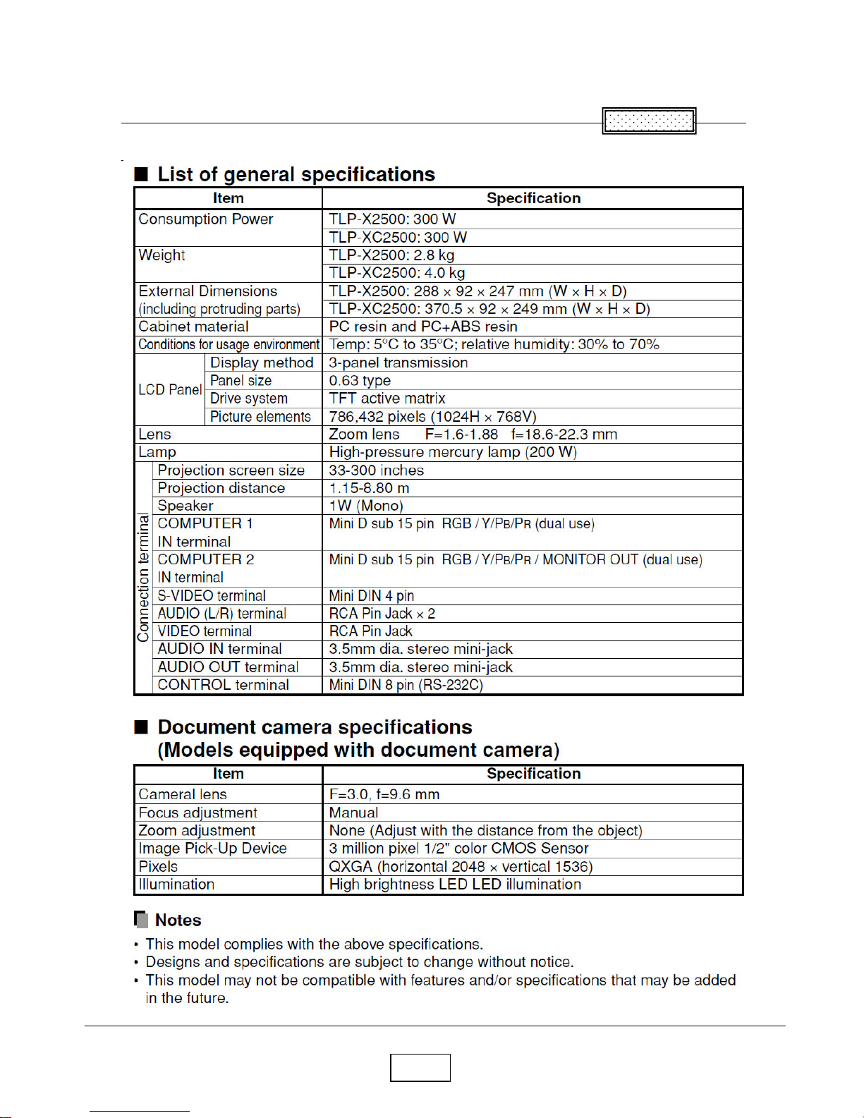
Specifications 1-1
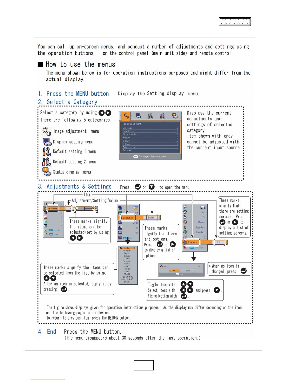
Using the Menus 1-3
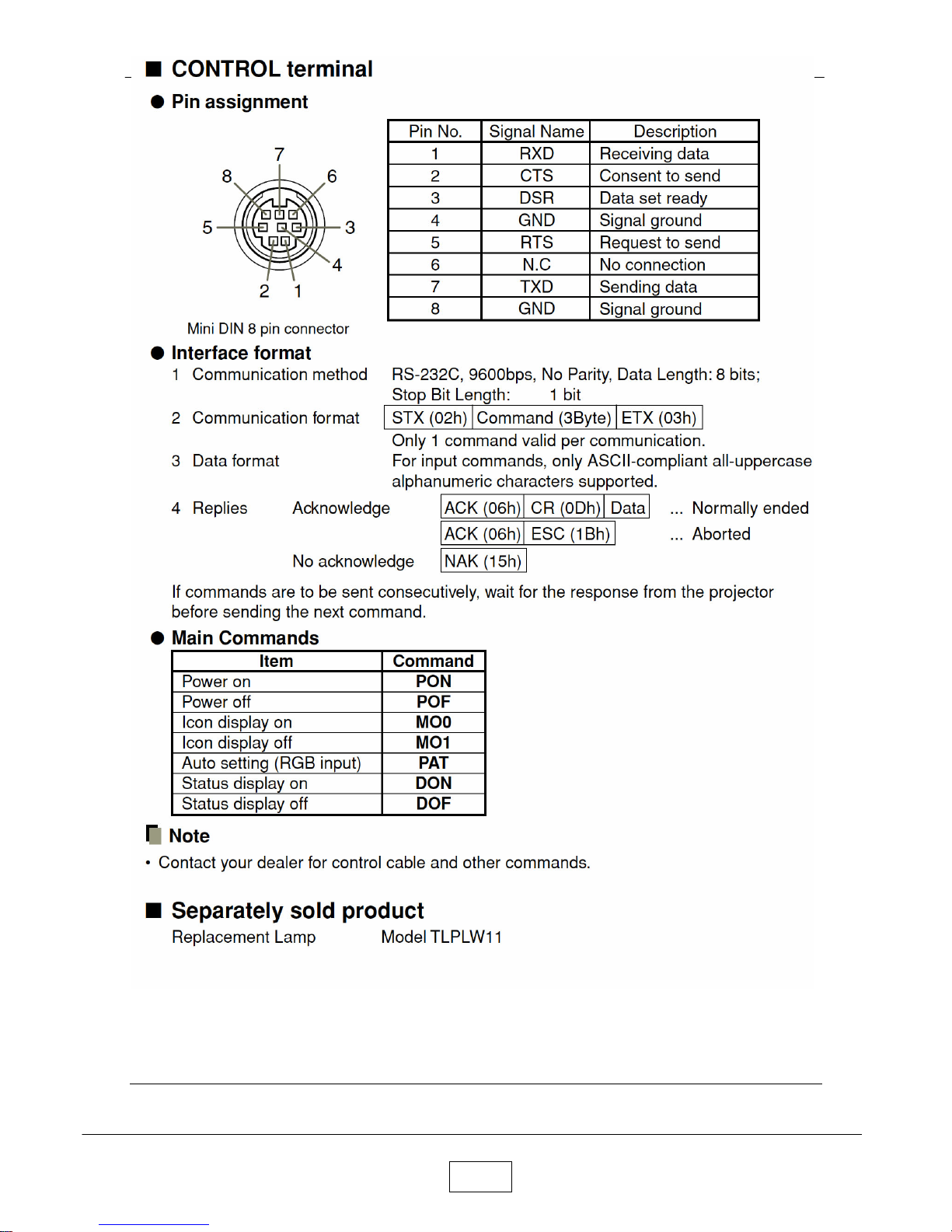
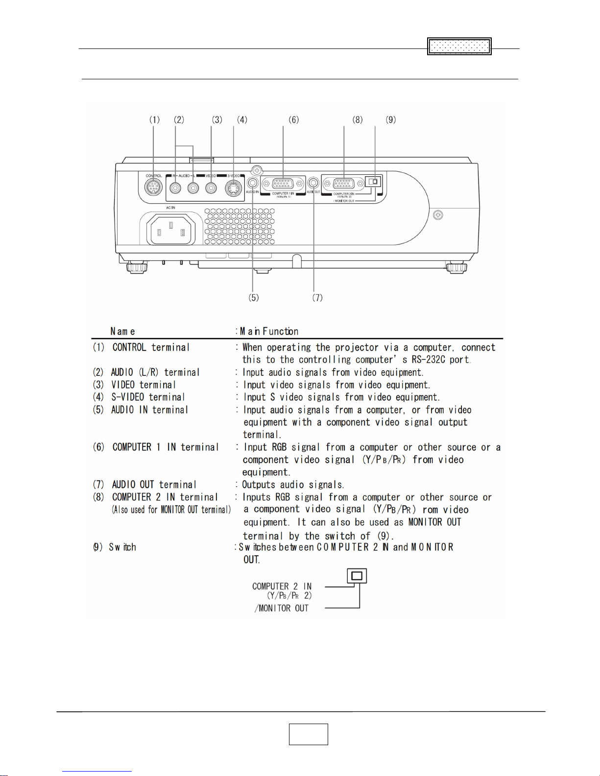
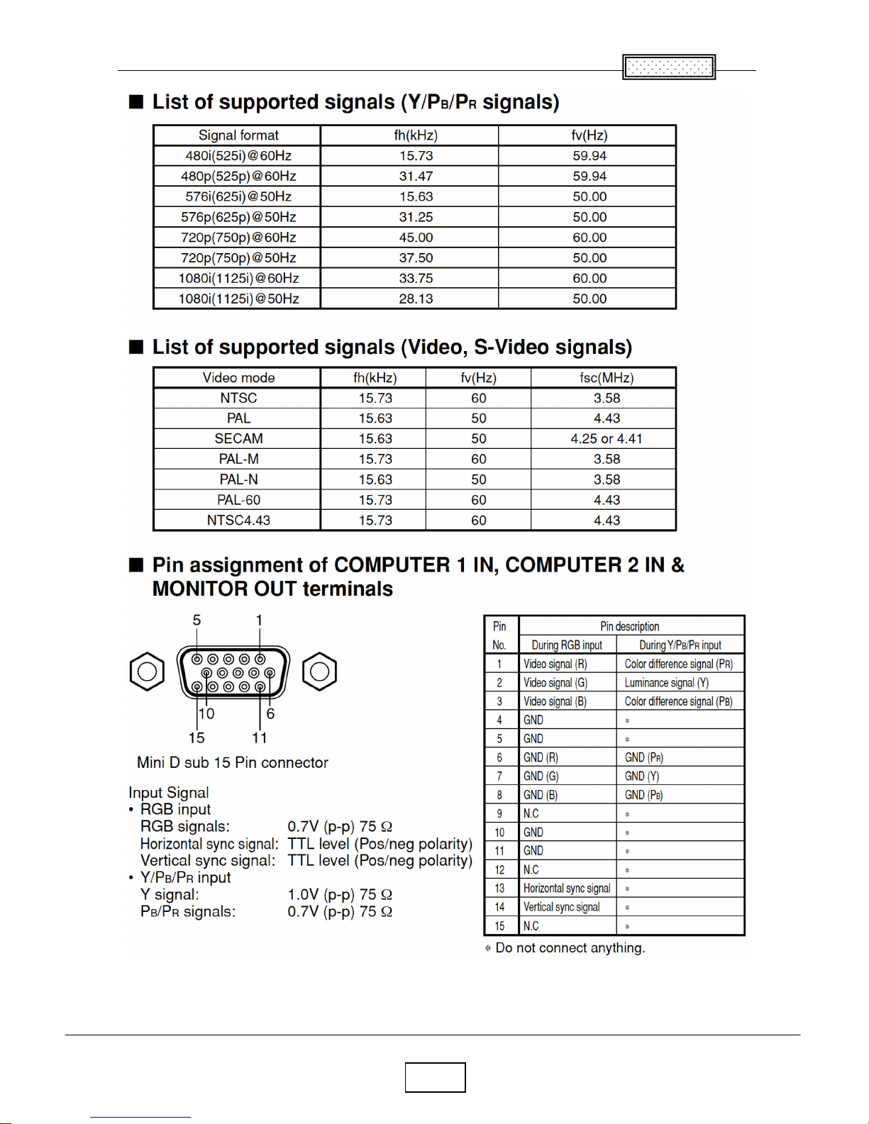
Names of the Terminals on the Rear Panel 1-4
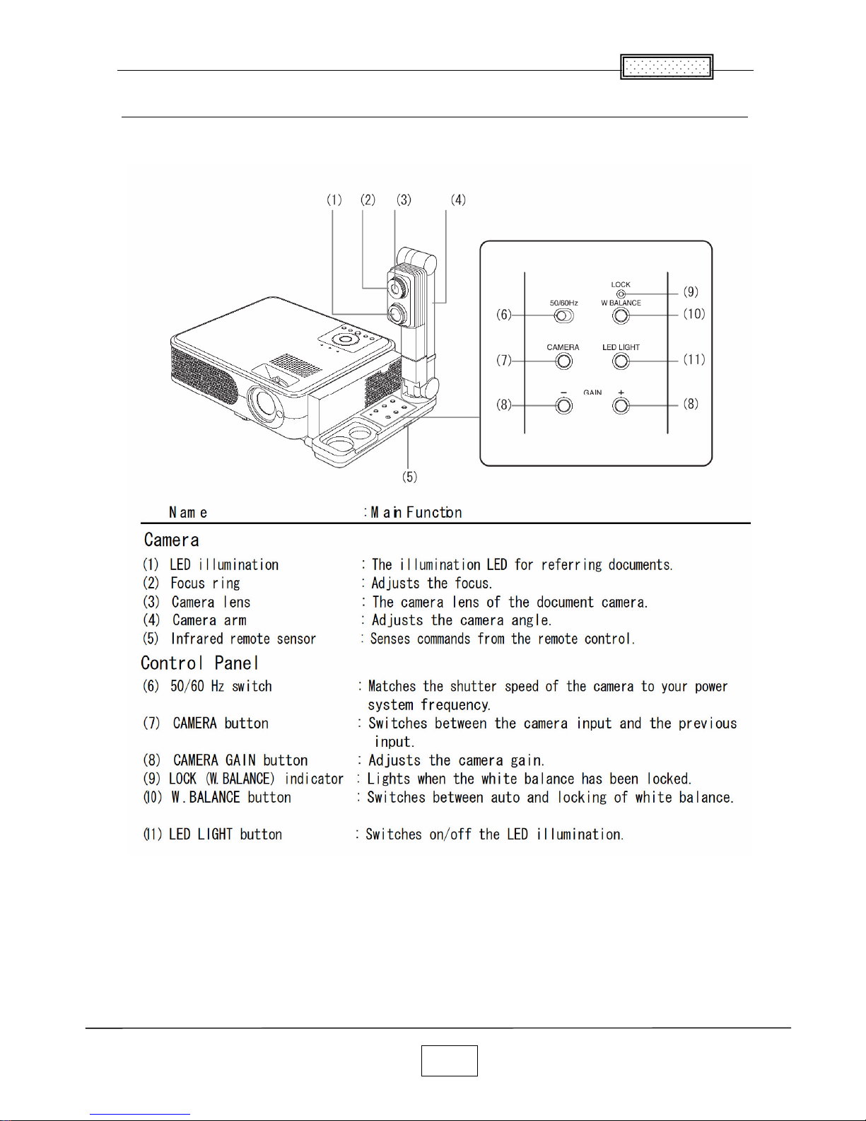
Name of each part on document camera 1-5
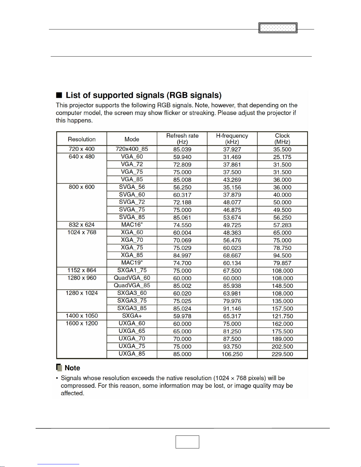
List of Supported Signals 1-6
Chapter 2 2-1
Replaceable Part Hierarchy 2-1
Required Tools 2-2
Parts Replacement 2-3
Replacement of optical parts 2-15
Chapter 3
3-1
SINGOWS 2000 3-1
Chapter 4 4-1
Firmware Upgrade 4-1
Chapter 5 5-1
Wiring Diagram 5-1
Block Diagram 5-2
Chapter 6 6-1
LED Display 6-1
Troubleshooting 6-2
Operation of Power Supply 6-9
Chapter 7 7-1
Electrical adjustment 7- 1
Chapter 8 8-1
Functional Test 8-1
Chapter 9 9-1
Spare Parts List 9-1
C
ontents
1-1
Chapter 1
Specifications
Chapter 1
Chapter 1
1-2
1-3
Chapter 1
Using the Menus
1-4
Chapter 1
Names of the Terminals on the Rear Panel
Chapter 1
1-5
Names of each part on document camera (models with a document camera)
Chapter 1
1-6
List of Supported Signals
Chapter 1
1-7
2-1
Chapter 2
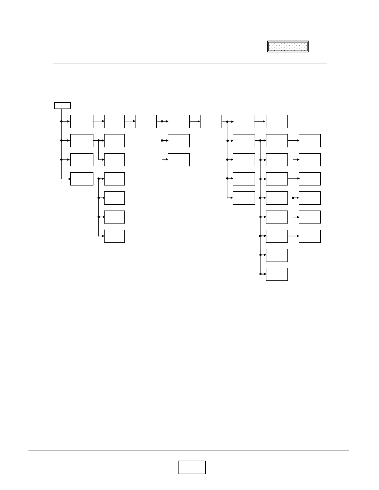
Replaceable Part Hierarchy
Replaceable Part Hierarchy
The flow chart below shows what parts must be removed to access each replaceable part in the projector.
The parts on the first level (Ex.Lamp cover) are accessible without removing any other parts.
The move levels down that a part is, the more parts you need to remove in order to access it.
Start
Camera
Main
Camera
KEY
Camera
CMOS
Camera
LED
Control
panel
LED
board
Lens
Camera
assy
Speaker
Exhaust
Fan
Balast
Fan
Powe
Filter Fan
Power
Filter
LCD
Panel
LCD Filter
Front
panel
LCD Fan
PBS Fan
Thermal
SW
Foot ADJ
Power
Main
Cover for
Power
Balast &
FAN assy
Optical
Engine
Intake
Fan
Color
wheel
Lamp
Driver
Door SW
Rear
panel
Lens cover
PCB Main
Lamp
cover
Lamp
Bracket
Top cover
Remocon
receiver
PCB
Sensor
Chapter 2
Chapter 2
2-2
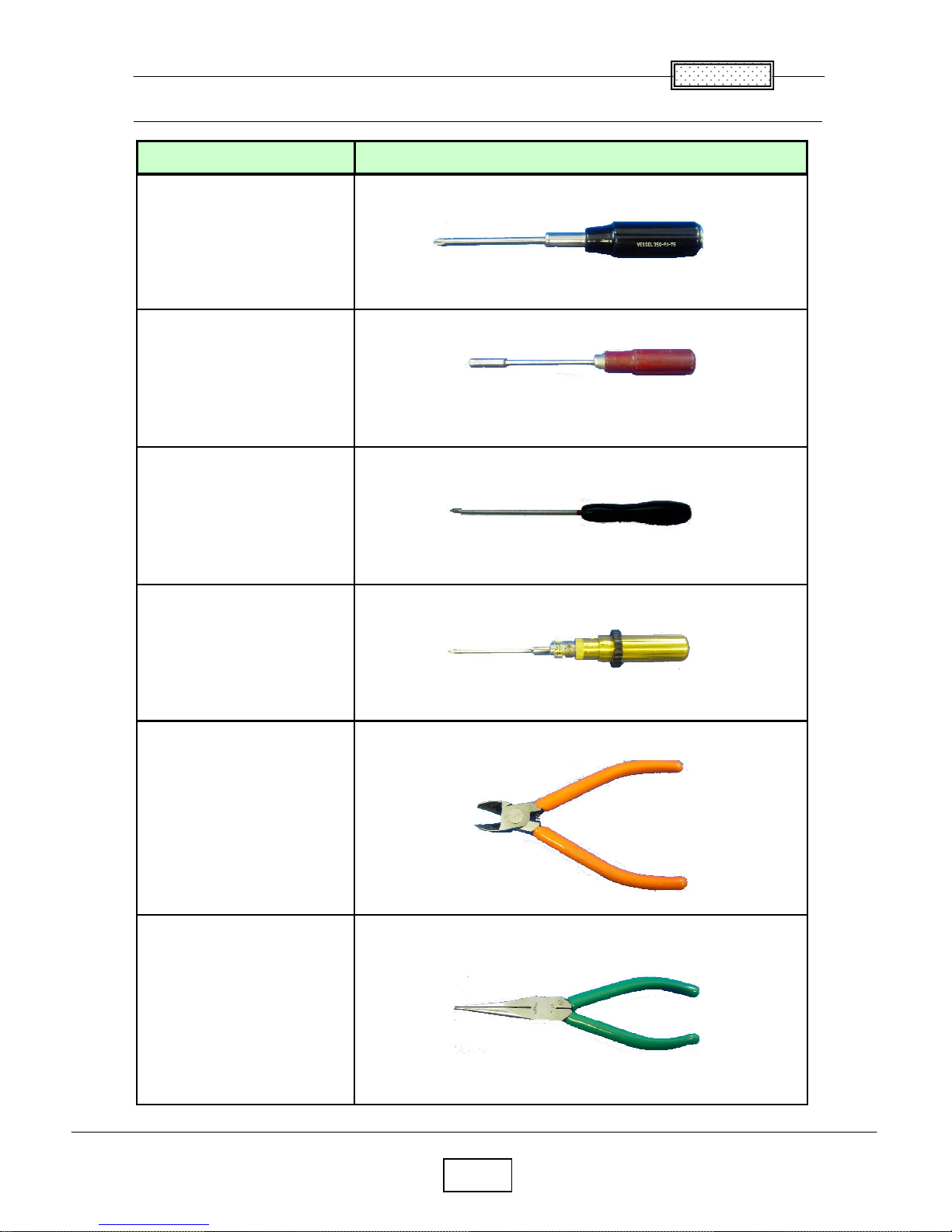
Required Tools
Cutting pliers
Driver bit (+) No 0
Torque driver bit (+) No 2
Nippers
Item Photo
Driver bit (+) No 2
Box driver M3
Chapter 2
2-3
Parts Replacement
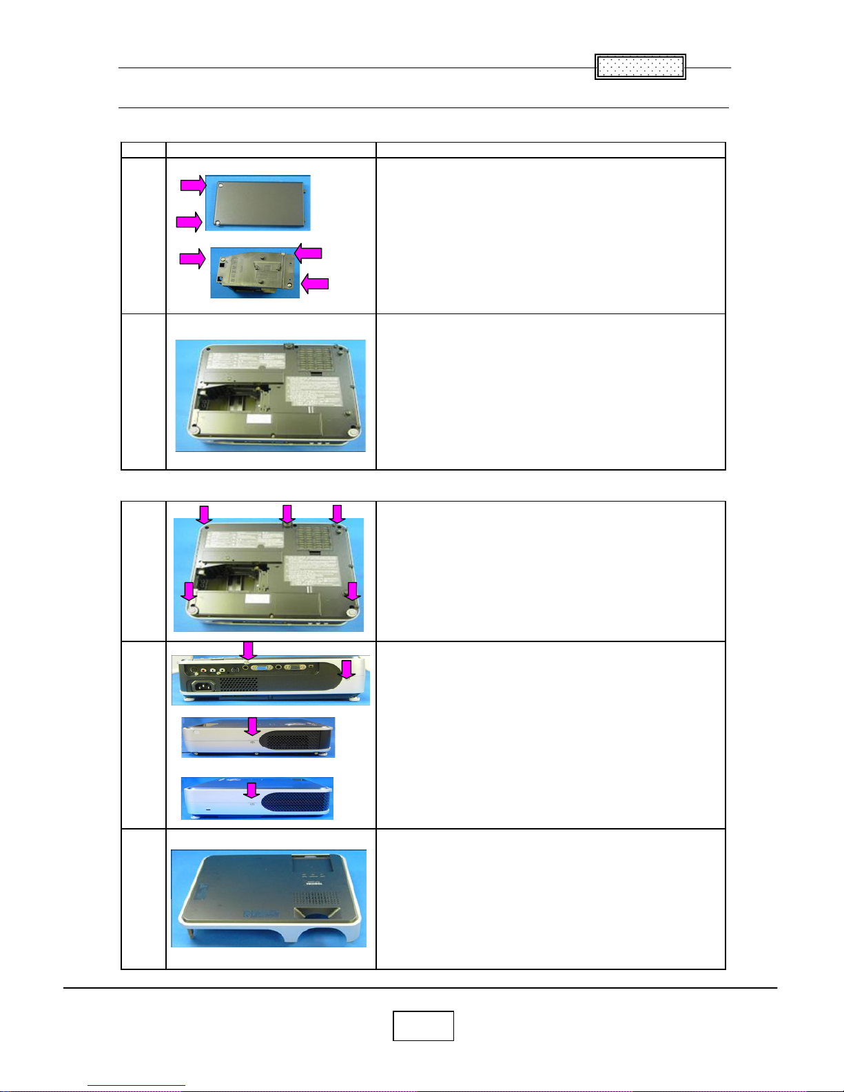
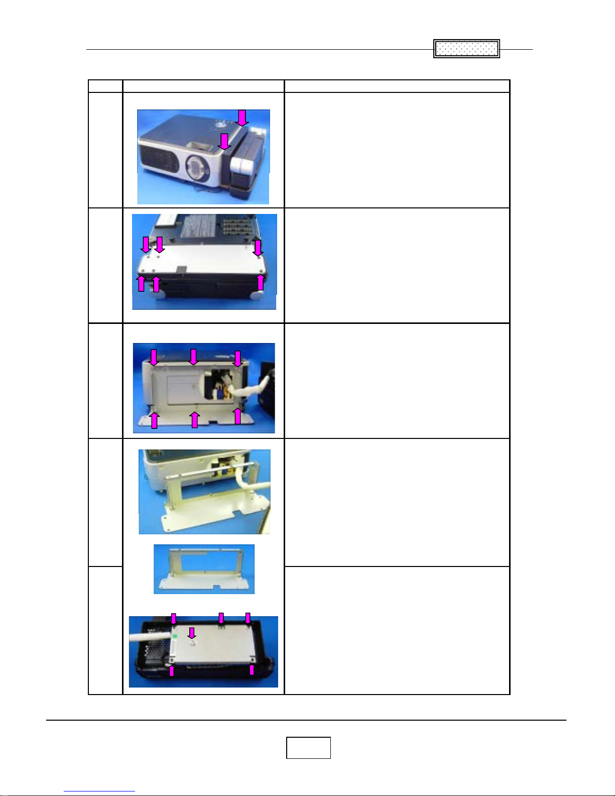
1.Lamp
No Fi
g
ure Explanation
Remove two lamp cover screws.
Remove three lamp screws.
Lamp is pulled out.
2.Top Cover
Remove five screws at the bottom.
Remove two screws at the rear.
Remove a screw at the ri
g
ht.
Remove a screw at the left.
Top cover is removed.
3
1
2
Chapter 2
2-4
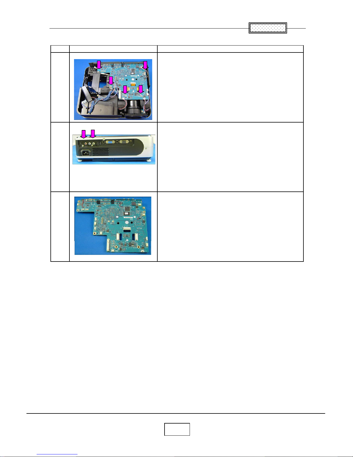
3.Main Board
Step Figure Explanation
A
ll the connectors on a main board unit are removed.
Remove five screws.
Remove two screws at the rear cover.
Main board is removed.
1
2
3
Chapter 2
2-5
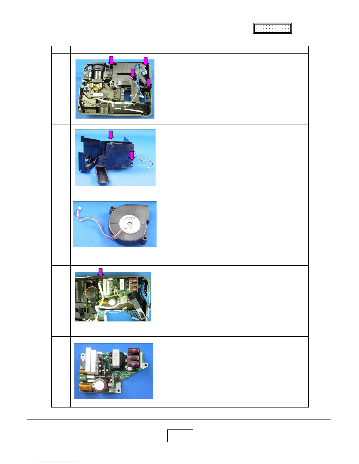
4.Main Power Unit
Step Figure Explanation
Remove four screws.
Cover & Power Intake FAN are removed.
Remove two screws.
Power Intake FAN are removed.
Remove a screw.
Main Power Unit is taken out.
5
3
1
2
4
Chapter 2
2-6
5.PBS & Ballast FANs
Step Figure Explanation
Remove six screws.
Balast & FAN assy is taken out.
Remove two screws.
Remove two screws.
Ballast FANs are removed.
PBS FANs are removed.
1
2
3
4
Chapter 2
2-7
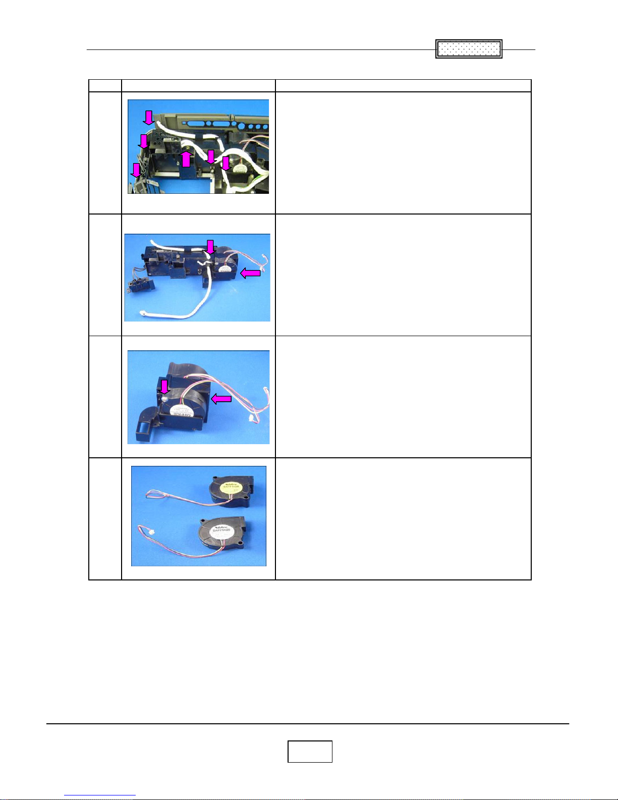
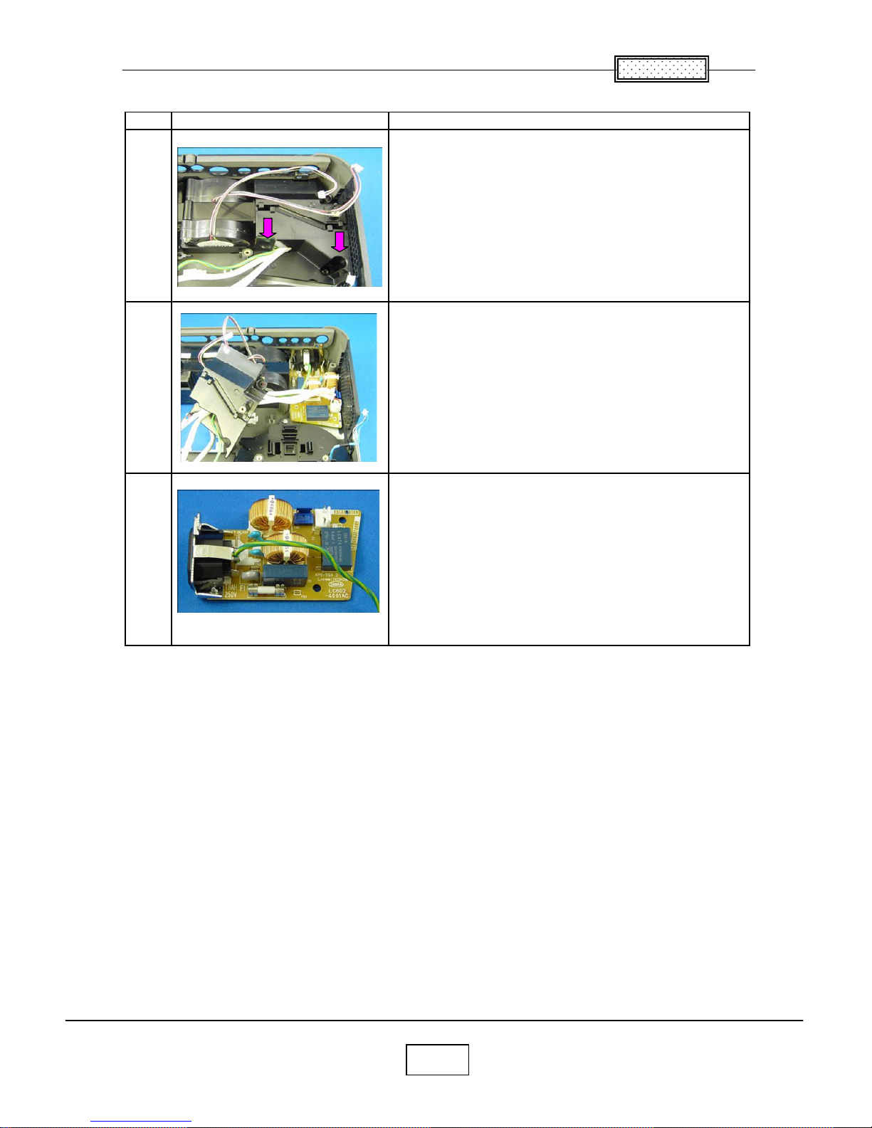
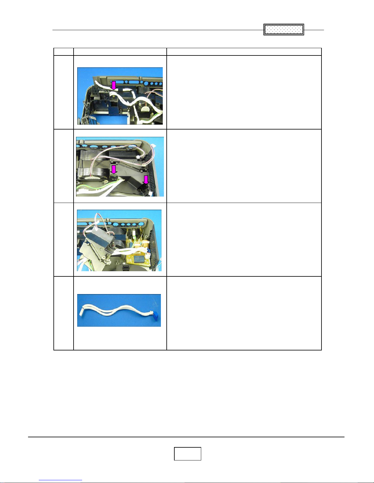
6.Exhaust Fan
Remove no screw.
Note.
May be very tight.
Exhaust Fan is removed.
7.Ballast
Remove two screws.
Cover is removed.
Pinch a stud with cutting pliers. (4 points)
Then pull up PC Board.
Ballast is removed.
1
2
1
2
3
Chapter 2
2-8
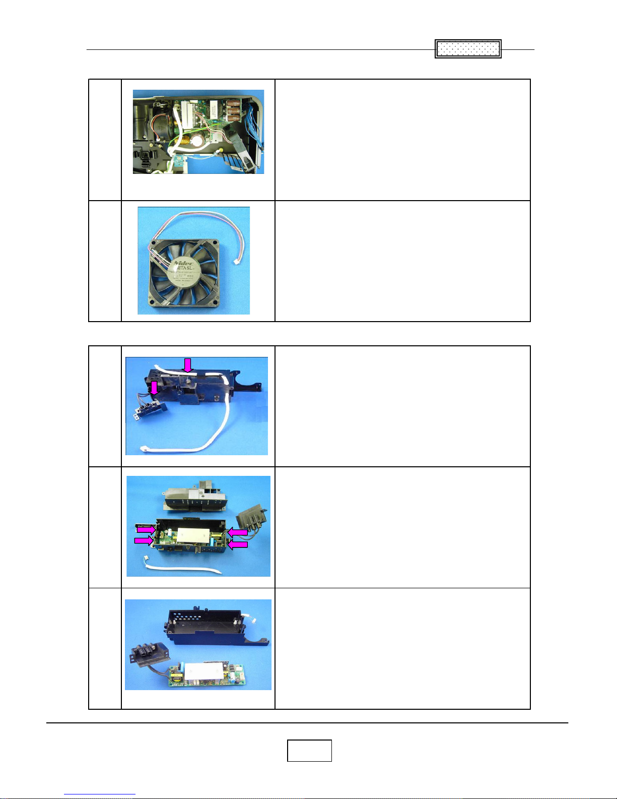
8.Filter Power
Step Figure Explanation
Remove two screws.
Cover is removed.
Filter Power is taken out.
1
2
3
Chapter 2
2-9
9.Thermal Switch
Step Figure Explanation
Remove a screws.
Remove two screws.
Cover is removed.
Thermal Switch is removed.
1
4
2
3
Chapter 2
2-10
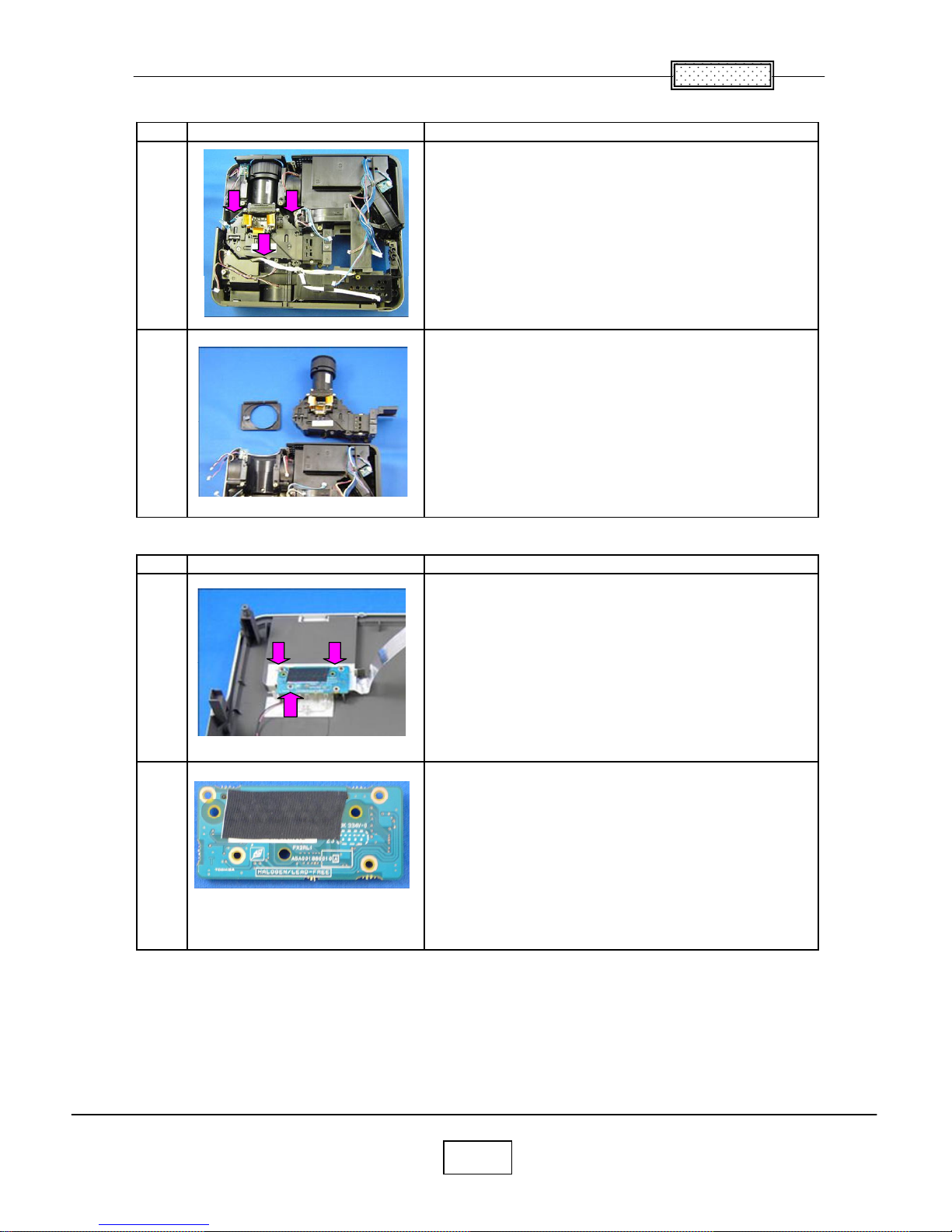
10.Optical Emgine
Step Figure Explanation
Remove three screws.
Optical Engine is taken out.
11.Relay Board
Step Figure Explanation
Remove three screws.
Relay Board is removed.
2
1
2
1
Chapter 2
2-11
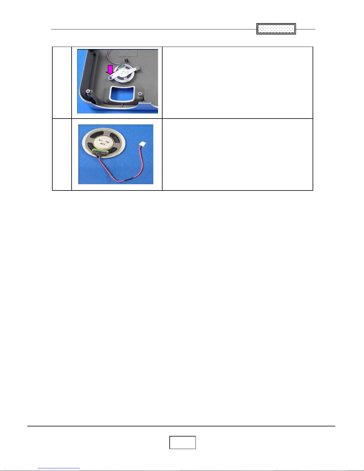
15.Speaker
Remove a screws.
Speaker is removed.
1
2
Chapter 2
2-12
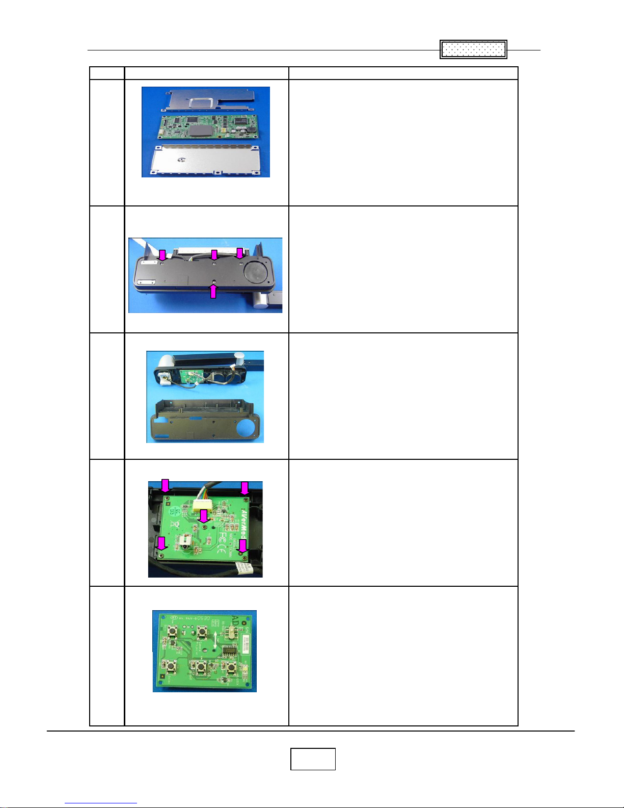
13.CAMERA ASSY.
No Figure Explanation
Remove two screws.
Remove six screws.
Remove six screws.
Remove cable connector.
Blaket base is removed.
Remove six screws.
1
2
3
4
5
Chapter 2
2-13
No Figure Explanation
Cover is removed.
Remove four screws.
Bottom cover is removed.
Remove five screws.
PC Board is removed.
6
7
8
10
9

Chapter 2
2-14
No Figure Explanation
Remove four screws.
Remove four screws.
LED illumination & Cover are removed.
Remove two screws.
Camera head is removed.
12
13
14
11
15
Chapter 2
2-15
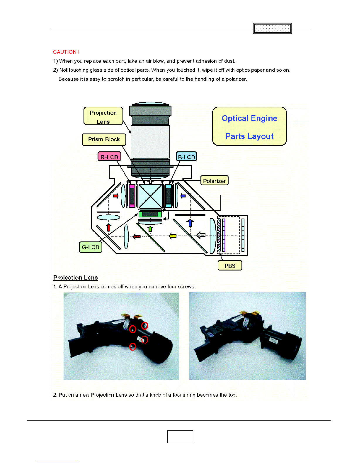
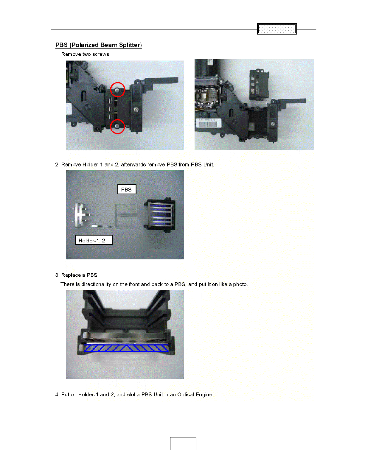
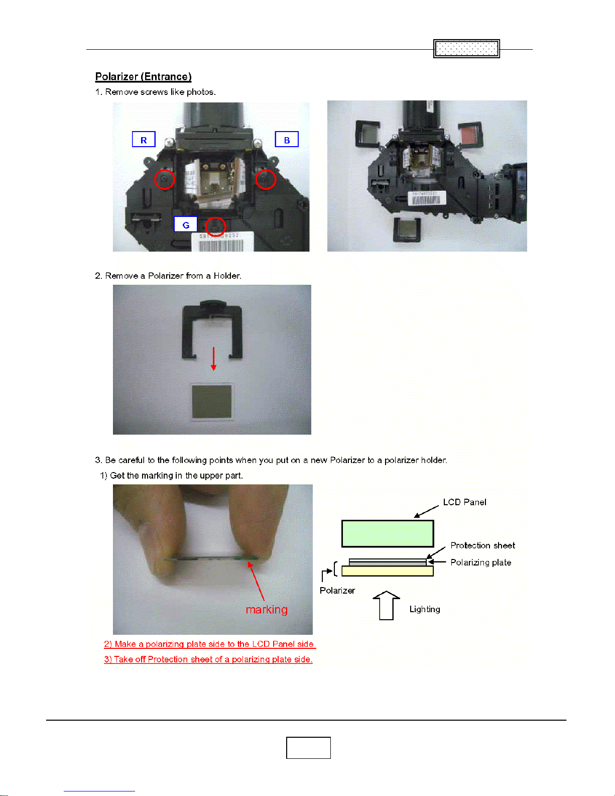
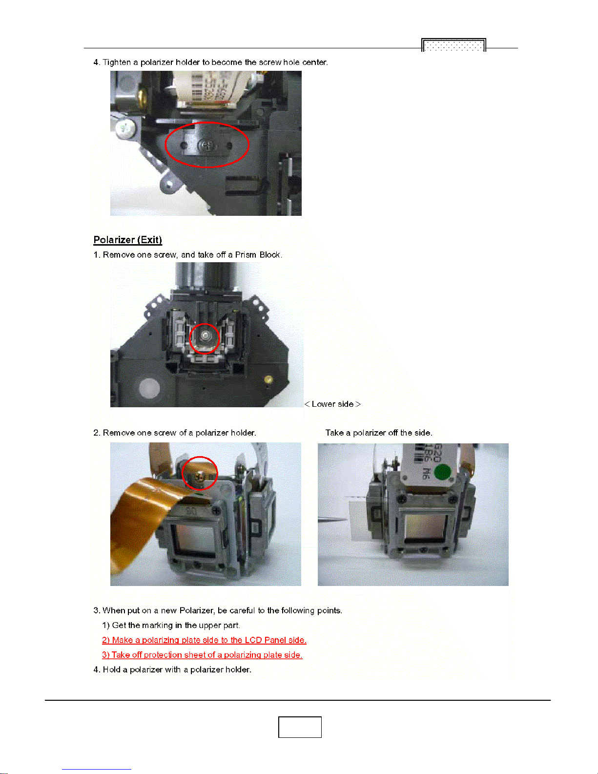
Replacement of Optical Parts
Chapter 2
2-16
Chapter 2
2-17
Chapter 2
2-18
 Loading...