

Toshiba TLP-X4100U, TLP X4100 User Manual
OWNER’S MANUAL
3LCD DATA PROJECTOR
TLP-X4100U

SAFETY PRECAUTIONS
The lightning flash with arrowhead symbol, within an equilateral
triangle, is intended to alert the user to the presence of uninsulated
“dangerous voltage” within the product’s enclosure that may be of
sufficient magnitude to constitute a risk of electric shock to persons.
The exclamation point within an equilateral triangle is intended to
alert the user to the presence of important operating and
maintenance (servicing) instructions in the literature accompanying
the appliance.
2
IMPORTANT PRECAUTIONS
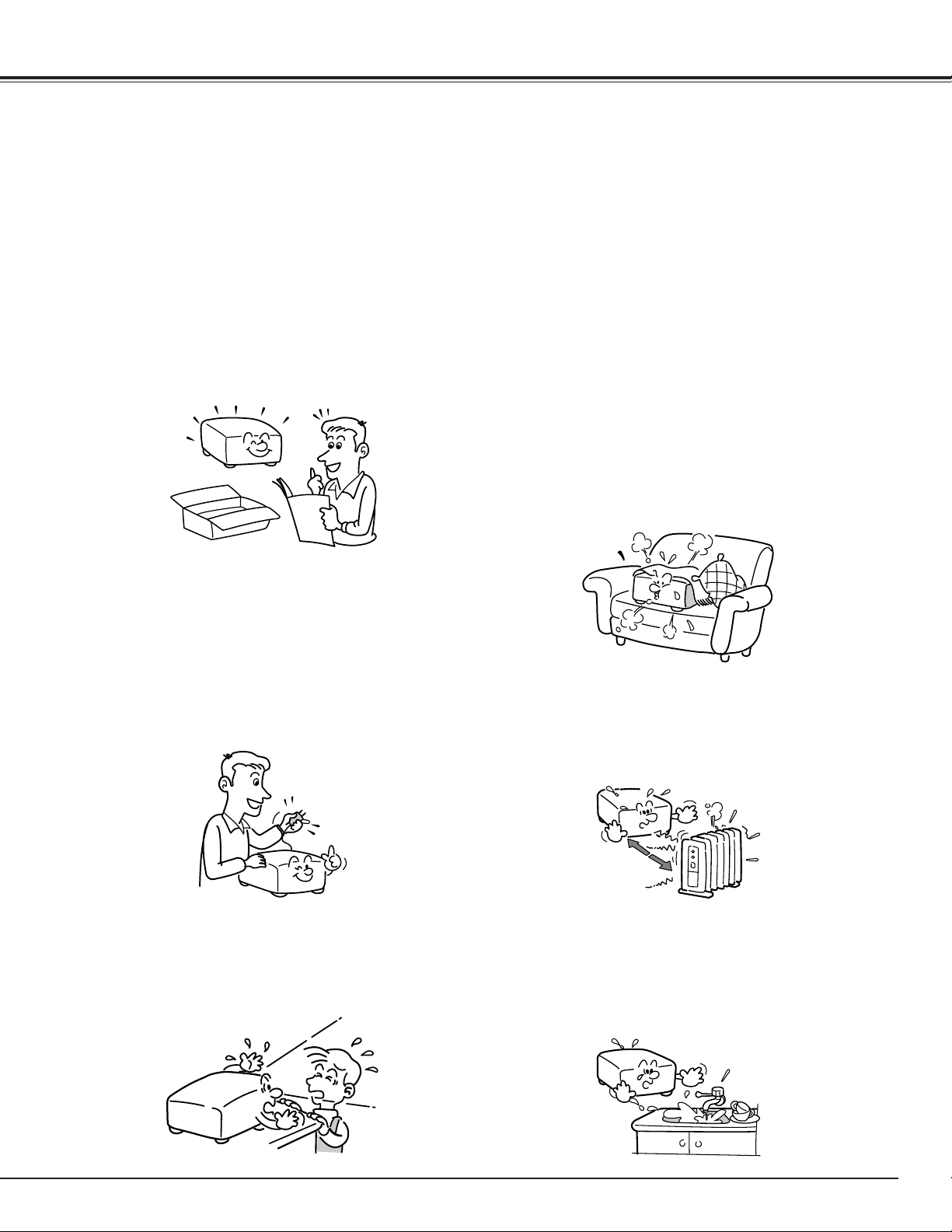
Save Original Packing Materials
The original shipping carton and packing materials will come in handy if you ever have to ship your LCD projector. For maximum
protection, repack the set as it was originally packed at the factory.
Avoid Volatile Liquid
Do not use volatile liquids, such as an insect spray, near the unit.
Do not leave rubber or plastic products touching the unit for a long time. They will mar the finish.
Moisture Condensation
Never operate this unit immediately after moving it from a cold location to a warm location. When the unit is exposed to such a
change in temperature, moisture may condense on the crucial internal parts. To prevent the unit from possible damage, do not
use the unit for at least 2 hours when there is an extreme or sudden change in temperature.
Exemption Clauses
• Toshiba Corporation bears no responsibility in the case of damages arising from earthquakes, fire not liable to Toshiba
Corporation, operating by third parties, other accidents, or use under abnormal conditions including erroneous or improper
operation and other problems.
• Toshiba Corporation bears no responsibility for incidental damages (lost profit, work interruption, corruption or loss of the
memory contents, etc.) arising from the use of or the inability to use this unit.
• Toshiba Corporation accepts no liability whatsoever for any damages arising from not having followed the descriptions in this
Owner’s Manual.
• Toshiba Corporation accepts no liability whatsoever for any damages arising from malfunctions arising from combination with
equipment or software that is not related to Toshiba Corporation.
In the spaces provided below, record the Model and Serial No. located at the bottom of your LCD projector.
Model No. Serial No.
Retain this information for future reference.
WARNING: TO REDUCE THE RISK OF FIRE OR ELECTRIC SHOCK, DO NOT EXPOSE THIS APPLIANCE TO
RAIN OR MOISTURE. DANGEROUS HIGH VOLTAGES ARE PRESENT INSIDE THE ENCLOSURE.
DO NOT OPEN THE CABINET. REFER SERVICING TO QUALIFIED PERSONNEL ONLY.
FCC Radio Frequency Interference Statement
Note: This equipment has been tested and found to comply with the limits for a Class A digital device, pursuant to part 15 of
the FCC Rules. These limits are designed to provide reasonable protection against harmful interference when the
equipment is operated in a commercial environment. This equipment generates, uses, and can radiates radio
frequency energy and, if not installed and used in accordance with the instruction manual, may cause harmful
interference to radio communications. Operation of this equipment in a residential area is likely to cause harmful
interference in which case the user will be required to correct the interference at his own expense.
WARNING: Changes or modifications made to this equipment, not expressly approved by Toshiba, or parties authorized by
Toshiba, could void the user’s authority to operate the equipment.
Notice: This Class A digital apparatus complies with Canadian ICES-003.
Cet appareil numérique de la classe A est conforme à la norme NMB-003 du Canada.
CAUTION: Laser beam is emitted when the laser button of the remote control is pressed. Do not look from the front of the
remote control. Do not face toward a person or to a mirror.
3
IMPORTANT SAFETY INSTRUCTIONS
CAUTION: PLEASE READ AND OBSERVE ALL WARNINGS AND INSTRUCTIONS GIVEN IN THIS
OWNER’S MANUAL AND THOSE MARKED ON THE UNIT. RETAIN THIS BOOKLET FOR
FUTURE REFERENCE.
This set has been designed and manufactured to assure personal safety. Improper use can result in electric
shock or fire hazard. The safeguards incorporated in this unit will protect you if you observe the following
procedures for installation, use and servicing. This unit is fully transistorized and does not contain any parts that
can be repaired by the user.
DO NOT REMOVE THE CABINET COVER, OR YOU MAY BE EXPOSED TO DANGEROUS VOLTAGE.
REFER SERVICING TO QUALIFIED SERVICE PERSONNEL ONLY.
1. Read Owner’s Manual
After unpacking this product, read the owner’s
manual carefully, and follow all the operating and
other instructions.
2. Power Sources
This product should be operated only from the type
of power source indicated on the marking label. If
you are not sure of the type of power supply to
your home, consult your product dealer or local
power company.
For products intended to operate from battery
power, or other sources, refer to the operating
instructions.
3. Source of Light
Do not look into the lens while the lamp is on. The
strong light from the lamp may cause damage to
your eyes or sight.
4. Ventilation
Openings in the cabinet are provided for ventilation
and to ensure reliable operation of the product and
to protect it from overheating, and these openings
must not be blocked or covered. The openings
should never be blocked by placing the product on
a bed, sofa, rug or other similar surface. This
product should not be placed in a built-in
installation such as a bookcase or rack unless
proper ventilation is provided or the manufacturer’s
instructions have been adhered to.
5. Heat
The product should be situated away from heat
sources such as radiators, heat registers, stoves,
or other products (including amplifiers) that
produce heat.
6. Water and Moisture
Do not use this product near water – for example,
near a bath tub, wash bowl, kitchen sink, or
laundry tub; in a wet basement; or near a
swimming pool and the like.
4
IMPORTANT SAFETY INSTRUCTIONS
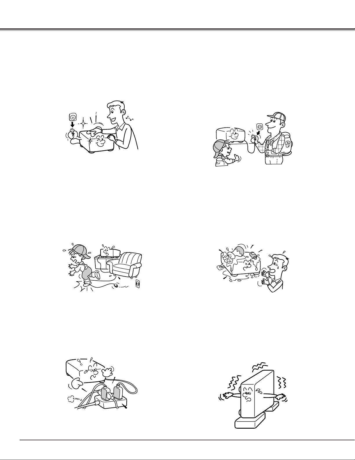
7. Cleaning
Unplug this product from the wall outlet before
cleaning. Do not use liquid cleaners or aerosol
cleaners. Use a damp cloth for cleaning.
8. Power-Cord Protection
Power-supply cords should be routed so that they
are not likely to be walked on or pinched by items
placed upon or against them, paying particular
attention to cords at plugs, convenience
receptacles, and the point where they exit from the
product.
9. Overloading
Do not overload wall outlets; extension cords, or
integral convenience receptacles as this can result
in a risk of fire or electric shock.
10. Lightning
For added protection for this product during
storm, or when it is left unattended and unused
for long periods of time, unplug it from the wall
outlet.
This will prevent damage to the product due to
lightning and power-line surges.
11. Object and Liquid Entry
Never push objects of any kind into this product
through openings as they may touch dangerous
voltage points or short-out parts that could result
in a fire or electric shock. Never spill liquid of any
kind on the product.
12. Do not place the product vertically
Do not use the product in the upright position to
project the pictures at the ceiling, or any other
vertical positions.
It may fall down and dangerous.

S3125A
5
IMPORTANT SAFETY INSTRUCTIONS
13. Stack Inhibited
Do not stack other equipment on this product or
do not place this product on the other equipment.
Top and bottom plates of this product develops
heat and may give some undesirable damage to
other unit.
14. Attachments
Do not use attachments not recommended by the
product manufacturer as they may cause
hazards.
15. Accessories
Do not place this product on an unstable cart,
stand, tripod, bracket, or table. The product may
fall, causing serious injury to a child or adult, and
serious damage to the product. Use only with a
cart, stand, tripod, bracket, or table
recommended by the manufacturer, or sold with
the product. Any mounting of the product should
follow the manufacturer’s instructions, and should
use a mounting accessory recommended by the
manufacturer.
A product and cart combination should be moved
with care. Quick stops, excessive force, and
uneven surfaces may cause the product and cart
combination to overturn.
16. Damage Requiring Service
Unplug this product from the wall outlet and refer
servicing to qualified service personnel under the
following conditions:
a) When the power-supply cord or plug is
damaged.
b) If liquid has been spilled, or objects have fallen
into the product.
c) If the product has been exposed to rain or
water.
d) If the product does not operate normally by
following the operating instructions. Adjust
only those controls that are covered by the
operating instructions as an improper
adjustment of other controls may result in
damage and will often require extensive work
by a qualified technician to restore the product
to its normal operation.
e) If the product has been dropped or damaged
in any way.
f) When the product exhibits a distinct change in
performance – this indicates a need for
service.
17. If glass components, including lens and lamp,
should break, contact your dealer for repair
service.
This product incorporates glass components,
including a lens and a lamp. If such parts should
break, please handle with care to avoid injury and
contact your dealer for repair service. The broken
pieces of glass may cause to injury.
In the unlikely event of the lamp rupturing,
thoroughly clean the area around the projector
and discard any edible items placed in that area.
18. Servicing
Do not attempt to service this product yourself as
opening or removing covers may expose you to
dangerous voltage or other hazards. Refer all
servicing to qualified service personnel.

6
IMPORTANT SAFETY INSTRUCTIONS
19. Replacement Parts
When replacement parts are required, be sure
the service technician has used replacement
parts specified by the manufacturer or have the
same characteristics as the original part.
Unauthorized substitutions may result in fire,
electric shock, or other hazards.
(Replacement of the lamp only should be made
by users.)
20. Safety Check
Upon completion of any service or repairs to this
product, ask the service technician to perform
safety checks to determine that the product is in
proper operating condition.

7
CONNECTING AC POWER CORD
NOTE ON POWER CORD
AC Power Cord must meet requirement of country where you use a projector.
Confirm an AC plug type with chart below and proper AC Power Cord must be used.
If supplied AC Power Cord does not match your AC outlet, contact your sales dealer.
To POWER CORD
CONNECTOR on your
projector.
Projector side AC Outlet side
Ground
To the AC Outlet.
(120 V AC)
For Continental Europe
For the U.S.A. and Canada
This projector uses nominal input voltages of 100-120 V or 200-240
V AC. This projector automatically selects correct input voltage. It
is designed to work with single-phase power systems having a
grounded neutral conductor. To reduce risk of electrical shock, do
not plug into any other type of power system.
Consult your authorized dealer or service station if you are not sure
of type of power supply being in use.
Connect a projector with a peripheral equipment before turning a
projector on. (Refer to pages 13 ~ 15 for connection.)
CAUTION
For safety, unplug AC Power Cord when an appliance is not
used.
When this projector is connected to outlet with AC Power Cord,
an appliance is in Stand-by Mode and consumes a little electric
power.
Connect AC Power Cord (supplied) to a projector.
AC outlet must be near this equipment and must
be easily accessible.
For the U.K.
To the AC Outlet.
(200 - 240 V AC)
To the AC Outlet.
(200 - 240 V AC)

TABLE OF CONTENTS
TRADEMARKS
● Apple, Macintosh, and PowerBook are trademarks or registered trademarks of Apple Computer,Inc.
● IBM and PS/2 are trademarks or registered trademarks of International Business Machines, Inc.
● Windows and PowerPoint are registered trademarks of Microsoft Corporation.
● Each name of corporations or products in the owner's manual is a trademark or a registered trademark of its
respective corporation.
8
FEATURES AND DESIGN..............9
PREPARATION...............................10
NAME OF EACH PART OF PROJECTOR............10
SETTING-UP PROJECTOR ..................................11
POSITIONING PROJECTOR..............................................11
ADJUSTABLE FEET ...........................................................12
MOVING PROJECTOR.......................................................12
CONNECTING PROJECTOR .........13
TERMINALS OF PROJECTOR .............................13
CONNECTING TO COMPUTER ...........................14
CONNECTING TO VIDEO EQUIPMENT ..............15
BEFORE OPERATION ...................16
OPERATION OF REMOTE CONTROL.................16
LASER POINTER FUNCTION ............................................16
REMOTE CONTROL BATTERIES INSTALLATION ...........17
TOP CONTROLS AND INDICATORS...................18
OPERATING ON-SCREEN MENU........................19
HOW TO OPERATE ON-SCREEN MENU .........................19
FLOW OF ON-SCREEN MENU OPERATION....................19
MENU BAR..........................................................................20
BASIC OPERATION .......................21
TURNING ON / OFF PROJECTOR.......................21
ADJUSTING SCREEN...........................................22
ZOOM ADJUSTMENT.........................................................22
FOCUS ADJUSTMENT.......................................................22
LENS SHIFT ADJUSTMENT...............................................22
KEYSTONE ADJUSTMENT................................................22
PICTURE FREEZE FUNCTION ..........................................23
NO SHOW FUNCTION .......................................................23
P-TIMER FUNCTION ..........................................................23
SOUND ADJUSTMENT.........................................23
COMPUTER MODE ........................24
SELECTING INPUT SOURCE ..............................24
SELECTING COMPUTER SYSTEM .....................24
PC ADJUSTMENT.................................................25
AUTO PC ADJUSTMENT ...................................................25
MANUAL PC ADJUSTMENT ..............................................26
COMPATIBLE COMPUTER SPECIFICATIONS.................28
PICTURE IMAGE ADJUSTMENT .........................29
IMAGE LEVEL SELECT......................................................29
IMAGE LEVEL ADJUSTMENT............................................30
PICTURE SCREEN ADJUSTMENT ......................31
VIDEO MODE .................................32
SELECTING INPUT SOURCE ..............................32
SELECTING VIDEO SYSTEM...............................33
PICTURE IMAGE ADJUSTMENT .........................34
IMAGE LEVEL SELECT......................................................34
IMAGE LEVEL ADJUSTMENT............................................35
PICTURE SCREEN ADJUSTMENT ......................36
SETTING.........................................37
SETTING MENU....................................................37
APPENDIX ......................................39
OPERATING WIRELESS MOUSE ........................39
MAINTENANCE.....................................................40
WARNING TEMP. INDICATOR ..........................................40
AIR FILTER CARE AND CLEANING ..................................40
CLEANING PROJECTION LENS........................................40
LAMP REPLACEMENT.......................................................41
LAMP REPLACE COUNTER ..............................................41
TROUBLESHOOTING...........................................42
TECHNICAL SPECIFICATIONS............................44

9
FEATURES AND DESIGN
This Multimedia Projector is designed with most advanced technology for portability, durability, and ease of use. This
projector utilizes built-in multimedia features, a palette of 16.77 million colors, and matrix liquid crystal display (LCD)
technology.
◆ Compatibility
This projector widely accepts various video and
computer input signals including;
● Computers
IBM-compatible or Macintosh computer up to 1280
x 1024 resolution.
● 6 Color Systems
NTSC, PAL, SECAM, NTSC 4.43, PAL-M or PALN color system can be connected.
● Component Video
Component video signal, such as a DVD player
output high definition TV signals including 480i,
480p, 575i, 575p, 720p, 1035i or 1080i, can be
connected.
● S-Video
S-Video signal, such as a S-VHS VCR output
signal, can be connected.
◆ High Resolution Image
This projector provides 1024 x 768 dots resolution for
computer input and 800 horizontal TV lines. Resolution
from a computer between XGA (1024 x 768) and SXGA
(1280 x 1024) is compressed into 1024 x 768 dots. This
projector cannot display image of over 1280 x 1024 dots.
When resolution of your computer is over than 1280 x
1024, reset a computer output for lower resolution.
◆ Multi-Scan System
This projector has Multi-Scan System to conform to
almost all computer output signals quickly. There is no
need for troublesome manual adjustment of frequency
and other settings.
◆ Keystone Correction
Positioning of a projector may result in distorted image
being displayed in a trapezoid shape. Keystone
Correction solves this problem by digitally altering
projection to produce undistorted images.
◆ Multilanguage Menu Display
Operation menu is displayed in; English, German,
French, Italian, Spanish, Portuguese, Dutch, Swedish,
Chinese, Korean or Japanese.
◆ One-Touch Auto PC Adjustment
Incoming computer video signals are recognized and
best adjustment is automatically set by Auto PC
Adjustment. No complicated setup is necessary and
projection is always precise.
◆ Digital Zoom (for Computer)
Digital Zoom function adjusts image size to approx. 1/4 ~
49 times of original image size, allowing you to focus on
crucial information at a presentation.
◆ Compact Design
This projector is extremely compact in size and weight.
It is designed to carry and work anywhere you wish to
use.
◆ Power Management
Power Management function is provided to reduce power
consumption while a projector is not in use.
This Power Management function operates to turn
Projection Lamp off when a projector detects signal
interruption and any button is not pressed over 5
minutes. Projection Lamp is automatically turned on
again when a projector detects signal or any operation
button is pressed.
This projector is shipped with this function ON.
◆ Wireless Mouse
Remote Control Unit supplied with this projector has
Wireless Mouse function for a connected computer. This
function enables you to operate both projector and
computer with Remote Control Unit only.
◆ Digital Visual Interface
This projector is equipped with DVI 24-pin terminal for
connecting DVI output from a computer.
◆ Laser Pointer Function
Remote Control Unit supplied with this projector includes
Laser Pointer function. This function helps you to make
a smart presentation on a projected screen.
◆ Motor-driven Lens Shift
Projection lens can be moved up and down with motordriven lens shift function. This function makes it easy to
provide projected image where you want.
Zoom and focus can be also adjusted with motor-driven
operation.
◆ Network Adapter Box (Optional)
Network Adapter Box is an optional product to control
and set up a projector via the network cable. By
accessing to the connected projector using the web
browser on your computer. It can be controlled and set
up the projector remotely. Contact the sales dealer
where you purchased this projector for optional parts.

10
PREPARATION
NAME OF EACH PART OF PROJECTOR
BOTTOM OF CABINET
BACK OF CABINET
HOT AIR EXHAUSTED !
Air blown from exhaust vent is hot. When
using or installing a projector, following
precautions should be taken.
● Do not put a flammable object near this vent.
● Keep rear grills at least 3’(1 m) away from
any object, especially heat-sensitive object.
● Do not touch this area, especially screws
and metallic parts. This area will become
hot while a projector is used.
This projector detects internal temperature
and automatically controls operating power
of Cooling Fans.
FRONT OF CABINET
LAMP COVER
ADJUSTABLE FEET
AND
FEET LOCK LATCHES
This projector is equipped with cooling fans for protection from
overheating. Pay attention to following to ensure proper ventilation
and avoid a possible risk of fire and malfunction.
● Do not cover vent slots.
● Keep side clear of any objects. Obstructions may block cooling
air.
AIR INTAKE VENTS
PROJECTION LENS
SPEAKERS
INFRARED
REMOTE RECEIVER
LENS COVER
POWER CORD
CONNECTOR
EXHAUST VENT
TERMINALS
AND CONNECTORS
TOP CONTROLS
AND INDICATORS
INFRARED
REMOTE RECEIVER
CARRYING
HANDLE
AIR INTAKE
VENT
When attached the Network Adapter Box
(optional part) to the projector, remove the
these parts.
Refer to the owner's manual in the optional
Network Adapter Box.
11
PREPARATION
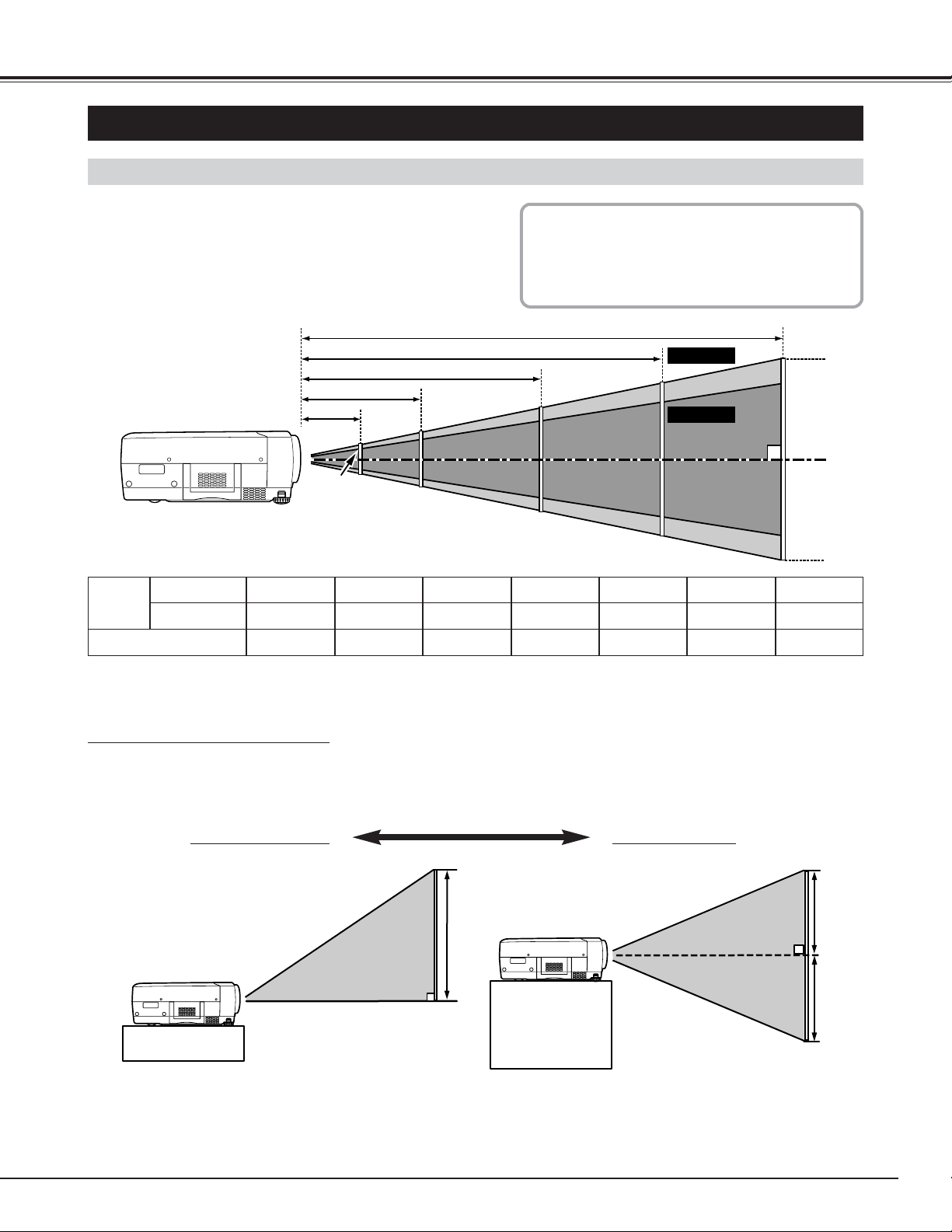
POSITIONING PROJECTOR
● This projector is designed to project on a flat
projection surface.
● Projector can be focused from 4.6’ (1.4m) ~ 48.3’
(14.7m).
● Refer to figure below to adjust screen size.
Screen
Size
Distance
40”
31”
4.6’ (1.4m)
ROOM LIGHT
Brightness in room has a great influence on
picture quality. It is recommended to limit
ambient lighting in order to provide best
image.
Min. Zoom
Max. Zoom
100”
77”
11.8’ (3.6m)
150”
115”
17.7’ (5.4m)
200”
154”
24.0’ (7.3m)
250”
192”
30.2’ (9.2m)
300”
231”
36.1’ (11.0m)
400”
308”
48.3’ (14.7m)
LENS SHIFT ADJUSTMENT
Projection lens can be moved up and down with motor-driven lens shift function. This function makes it easy to
provide projected image where you want. U/D ratio can be adjusted 10 : 0 ~ 1 : 1 (refer to figure below.). Refer
to P 22 for operation.
Highest (10 : 0) Lowest (1 : 1)
SETTING-UP PROJECTOR
11.8’(3.6m)
4.6’(1.4m)
100”
77”
40”
31”
24.0’(7.3m)
200”
154”
48.3’(14.7m)
36.1’(11.0m)
300”
231”
Max. Zoom
Min. Zoom
400”
308”
1
10 : 0
1

12
PREPARATION
CAUTION IN CARRYING OR TRANSPORTING A PROJECTOR
● Do not drop or bump a projector, otherwise damages or malfunctions may result.
● When carrying a projector, use a suitable carrying case.
● Do not transport a projector by using a courier or transport service in an unsuitable transport case. This
may cause damage to a projector. To transport a projector through a courier or transport service, consult
your dealer for best way.
MOVING PROJECTOR
Use Carry Handle when moving a Projector.
When moving a projector, replace lens cover and retract
feet to prevent damage to lens and cabinet.
When this projector is not in use for an extended period,
put it into case (dust cover) supplied with this projector.
ADJUSTABLE FEET
Picture tilt and projection angle can be adjusted by
rotating ADJUSTABLE FEET. Projection angle can be
adjusted to 10.5 degrees.
Lift front of a projector and pull FEET LOCK LATCHES
on both sides of a projector.
1
ADJUSTABLE FEET FEET LOCK
LATCHES
Release FEET LOCK LATCHES to lock ADJUSTABLE
FEET and rotate ADJUSTABLE FEET to fine tune
position and tilt.
2
To shorten ADJUSTABLE FEET, lift front of a projector
and pull and undo FEET LOCK LATCHES.
Position and keystone distortion of image can be adjusted
using Menu Operation. (Refer to P 22 and 37.)
3
NOTE :
THIS PROJECTOR SHOULD BE SET IN THE WAY
INDICATED. PROJECTION LAMP MAY MALFUNCTION.
13
CONNECTING PROJECTOR
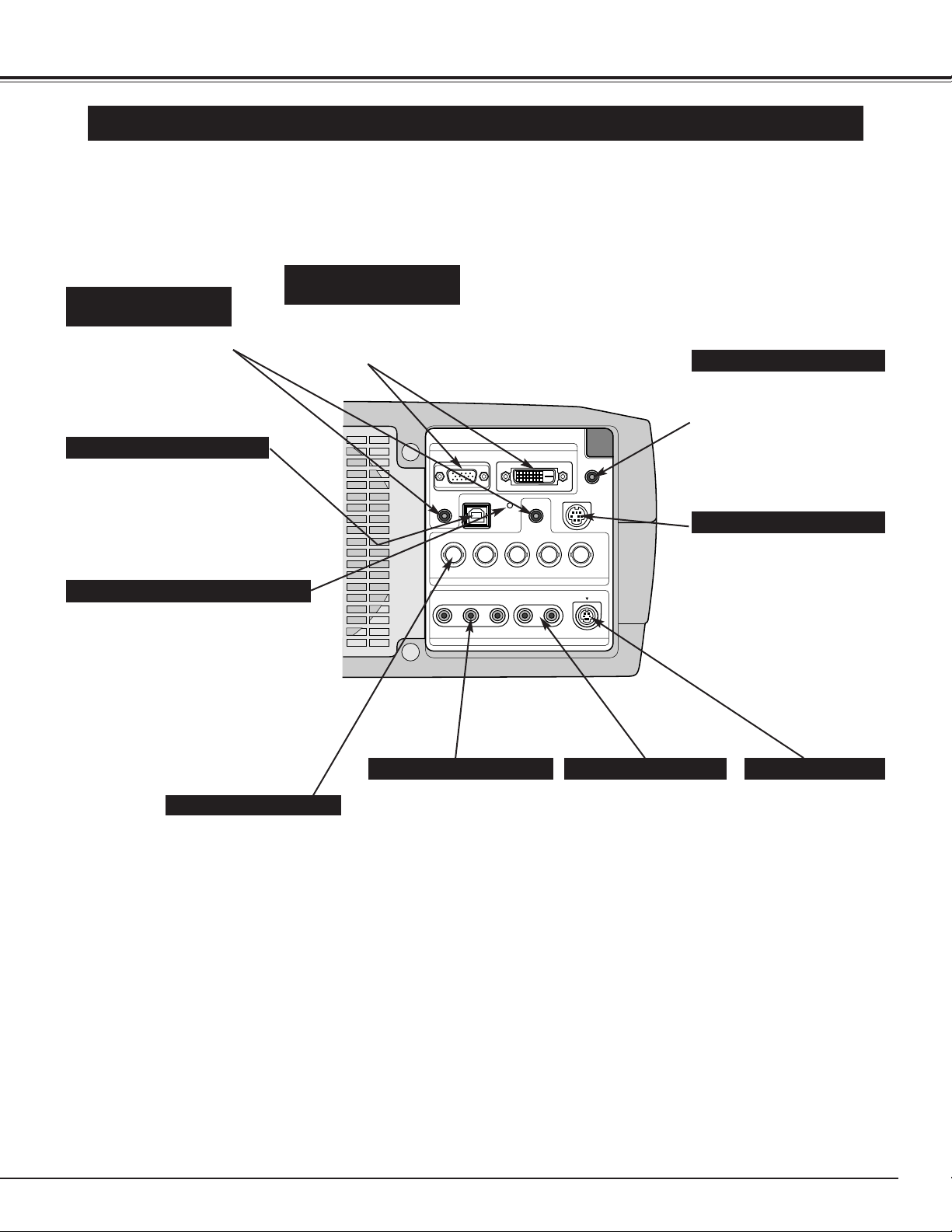
TERMINALS OF PROJECTOR
When controlling computer
with Remote Control Unit of
this projector, connect mouse
port of your personal computer
to this connector. (Refer to
P14.)
Connect S-VIDEO
output from video
equipment to this
jack. (Refer to P15.)
Connect an audio output
(stereo) from computer to
these jacks.
(Refer to P14.)
Connect an audio output
from video equipment to
these jacks.
(Refer to P15.)
CONTROL PORT CONNECTOR
COMPUTER AUDIO
INPUT (1 and 2) JACKS
AUDIO INPUT JACKS
VIDEO INPUT JACKS
S-VIDEO INPUT JACK
Connect composite video
output from video equipment
to VIDEO/Y jack or connect
component video outputs to
VIDEO/Y, Cb/Pb and Cr/Pr
jacks. (Refer to P15.)
Connect computer (digital/analog)
output to one of these terminals.
(Refer to P14.)
COMPUTER INPUT
TERMINALS (DIGITAL/ANALOG)
This projector has input and output terminals on its back for connecting computers and video equipment. Refer to figures on
pages 13 to 15 and connect properly.
This projector uses a micro processor
to control this unit, and occasionally,
this micro processor may malfunction
and need to be reset. This can be
done by pressing RESET button with a
pen, which will shut down and restart
unit. Do not use RESET function
excessively.
RESET BUTTON
When controlling computer with
Remote Control Unit of this
projector, connect mouse port
of your personal computer to
this terminal. (Refer to P14.)
USB CONNECTOR (Series B)
✽ Do not press this button. This button
is used for our optional accessories.
Connect component video
output (Y, Cb, Cr or Y, Pb, Pr)
from video equipment to
VIDEO/Y, Cb/Pb and Cr/Pr
jacks or connect computer
output {5 BNC Type (Green,
Blue, Red, Horiz. Sync and
Vert. Sync.)} from computer
to G, B, R, H/V and V jacks.
(Refer to P14 and 15.)
5 BNC INPUT JACKS
When using Wired/Wireless
Remote Control Unit as Wired
Remote Control, Connect
Wired Remote Control Unit to
this jack with Remote Control
Cable (supplied).
R/C JACK
INPUT 1
ANALOG DIGITAL(DVI-D)
RESET
USB
AUDIO 1 AUDIO 2
GBRH/V V
VIDEO/Y Cb/Pb Cr/Pr
VIDEO/Y Cb/Pb Cr/Pr
INPUT 2
INPUT 3
R–AUDIO–L
(
MONO
R/C JACK
CONTROL PORT
S–VIDEO
)
14
CONNECTING PROJECTOR
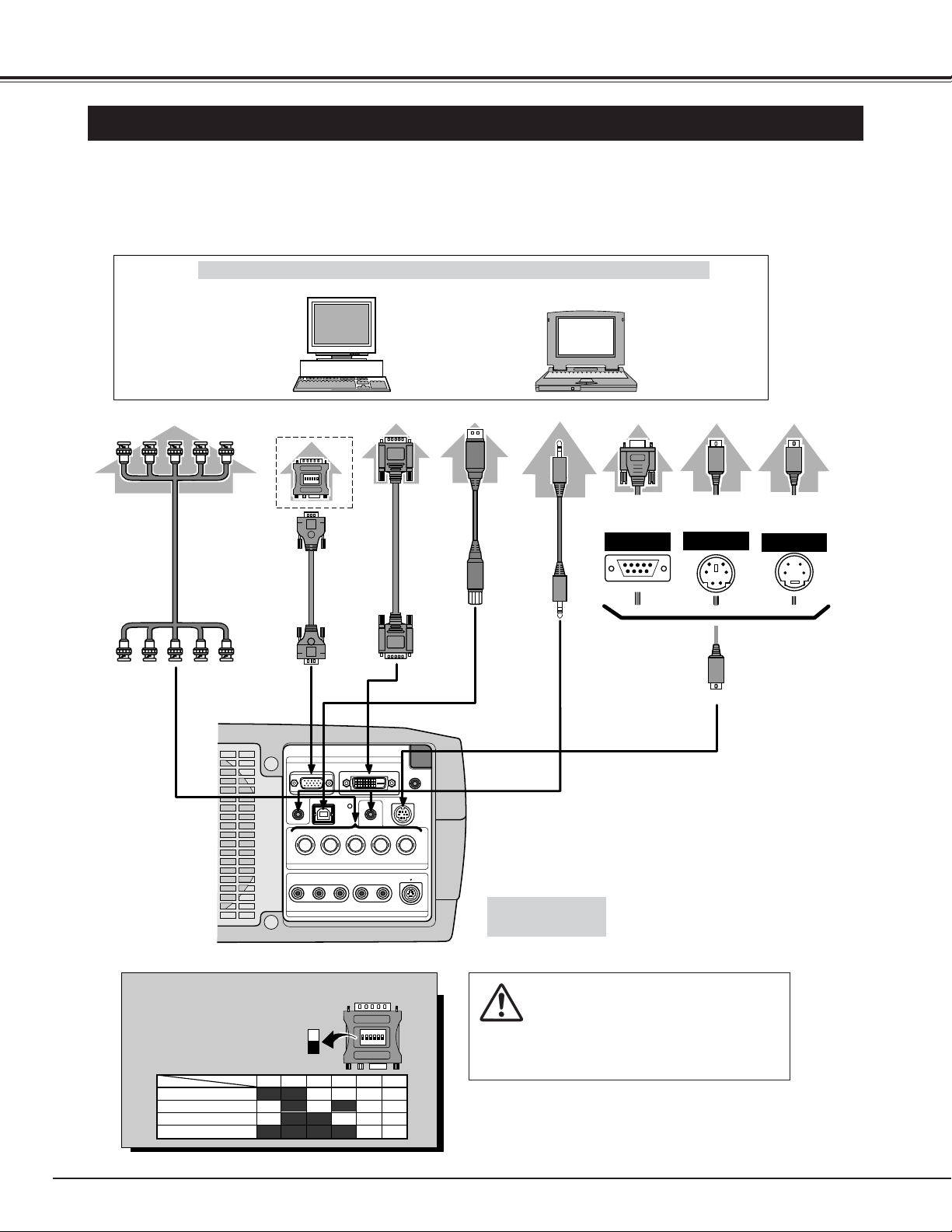
CONNECTING TO COMPUTER
IBM-compatible computer or Macintosh computer (VGA / SVGA / XGA / SXGA)
VGA Cable
Monitor Output
Desktop type Laptop type
Control Cable
for Serial Port
Terminal
Serial port
PS/2 port
Audio Output
CONTROL
PORT
COMPUTER
AUDIO IN 1 or 2
COMPUTER IN ANALOG
Use one of these Control
Cables corresponding with
terminal of your computer.
ADB port
Cables used for connection (✽ = Cable or adapter is not supplied with this projector.)
Control Cable
for PS/2 Port
Control Cable
for ADB Port
Audio
Cable
✽
(stereo)
NOTE :
When connecting cable, power cords of both
a projector and external equipment should
be disconnected from AC outlet. Turn a
projector and peripheral equipment on
before computer is switched on.
USB port
MAC Adapter
Set slide switches
according to chart
below.
• VGA Cable (HDB 15 pin)
• DVI-Digital Cable (for Single Link T.M.D.S.)
✽
• BNC Cable ✽
• Control Cable for PS/2 Port, Serial Port or ADB Port
• USB Cable ✽
• MAC Adapter (When connecting to Macintosh computer)
• Audio Cables (RCA x 2 and Mini Plug (stereo) x 1)
✽
Terminals
of a Projector
Terminal
Terminal
DVI
Cable
✽
Monitor Output
USB
COMPUTER IN DIGITAL
Set switches as shown in table
below depending on RESOLUTION MODE that you want to
use before you turn on projector and computer.
◆ MAC ADAPTER
USB
Cable
✽
BNC
Cable
✽
ANALOG DIGITAL(DVI-D)
USB
AUDIO 1 AUDIO 2
GBRH/V V
VIDEO/Y Cb/Pb Cr/Pr
VIDEO/Y Cb/Pb Cr/Pr
INPUT 1
CONTROL PORT
RESET
INPUT 2
R–AUDIO–L
S–VIDEO
R/C JACK
13" MODE (640 x 480)
16" MODE (832 x 624)
19" MODE (1024 x 768)
123456
OFF OFF OFF OFF
ON
OFF
OFF OFF OFF
OFFON ON
OFFOFF OFF OFF
ON ON
ON ON
INPUT 3
ON
1
OFF OFFON ONON ON21" MODE (1152 x 870)
2 3 4 5 6
(
MONO
)
DIP

15
CONNECTING PROJECTOR
CONNECTING TO VIDEO EQUIPMENT
Video Source (example)
Video Cassette Recorder Video Disc Player
S-VIDEO
Cable ✽
Terminals
of a Projector
S-VIDEO Output
Cables used for connection (✽ = Cable is not supplied with this projector.)
• Video Cable (RCA x 1 or RCA x 3)
✽
• BNC Cable ✽
• S-VIDEO Cable ✽
• Audio Cable (RCA x 2) ✽
NOTE :
When connecting cable, power cords of
both a projector and external equipment
should be disconnected from AC outlet.
Audio Cable
(RCA x 2) ✽
AUDIO IN
S-VIDEO
Y - Cb/Pb - Cr/Pr
VIDEO
Component video output equipment.
(such as DVD player or high-definition TV source.)
Composite
Video Output
Component Video Output
(Y, Cb/Pb, Cr/Pr)
Component Video Output
(Y, Cb/Pb, Cr/Pr)
Y - Cb/Pb - Cr/Pr
Video Cables
(RCA x 1 or
RCA x 3
) ✽
BNC Cable ✽
Audio Output
Composite
Video Output
VIDEO
INPUT 1
ANALOG DIGITAL(DVI-D)
RESET
USB
AUDIO 1 AUDIO 2
GBRH/V V
VIDEO/Y Cb/Pb Cr/Pr
VIDEO/Y Cb/Pb Cr/Pr
INPUT 2
INPUT 3
R–AUDIO–L
(
MONO
R/C JACK
CONTROL PORT
S–VIDEO
)
 Loading...