

Toshiba TLP-X11U, TLP-X10E, TLP-X20U, TLP-X21U, TLP-X11E Service Manual
...
FILE NO. 330-200008
SUPPLEMENT
SERVICE MANUAL
3LCD DATA PROJECTOR
TLP-X10U/11U/20U/21U
TLP-X10E/11E/20E/21E
TLP-X10Y/11Y/20Y/21Y
TLP-X20C/21C
TXP-X20/21
FAN
ON
BUSY
LAMP
TEMP
ANDBY
ON/ST
INPUT
MENU
EXIT
ENTER
.
OL/ADJ
V
SET
AUTO
ONE
KEYST
AUTO
COMPUTER IN 2CONTROL
)
R
/P
COMPUTER IN 1
B
Y/P
(
USB MONITOR OUT
S-VIDEO
VIDEO
VIDEO IN
R - AUDIO - L
O
I
AUD
IN
AUDIO
OUT
SAFETY PRECAUTION
WARNING: Service should not be attempted by anyone unfamiliar with the necessary precautions on this
projector. The following are the necessary precautions to be observed before servicing this chassis.
1. An isolation Transformer should be connected in the power line between the projector and the AC Iine
before any service is performed on the projector.
2. When replacing a chassis in the cabinet, always be certain that all the protective devices are put back in
place, such as; non-metallic control knobs, insulating covers, shields, isolation resistor-capacitor network
etc.
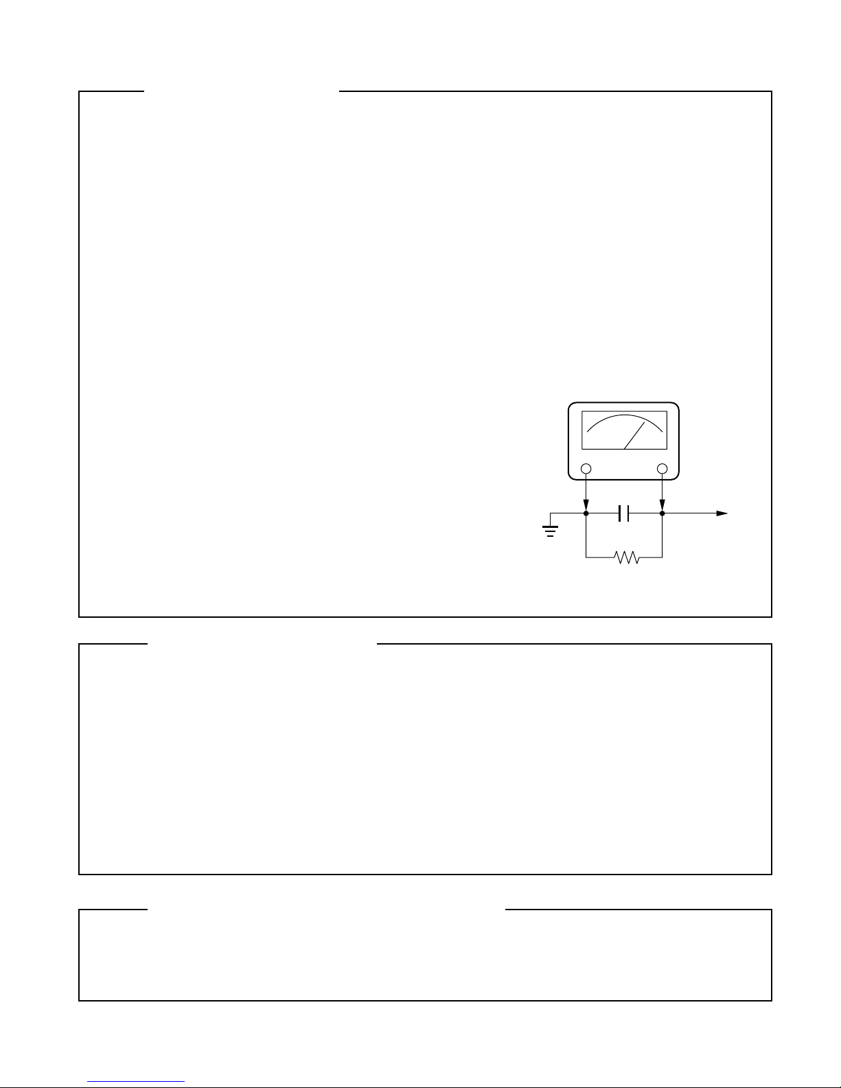
3. Before returning the set to the customer, always perform an AC Ieakage current check on the exposed
metallic parts of the cabinet, such as terminals, screwheads, metal overlays, control shafts etc. to be sure
the set is safe to operate without danger of electrical shock. Plug the AC Iine cord directly into a AC outlet
(do not use a line isolation transformer during this check). Use an AC voltmeter having 5000 ohm per volt
or more sensitivity in the following manner: Connect a1500 ohm 10W resistor, paralleled by a 0.15 uF, AC
type capacitor, between a known good earth
ground (water pipe, conduit, etc.) and the exposed
metallic parts, one at a time. Measure the AC
voltage across the combina-tion of 1500 ohm
resistor and 0.15 uF capacitor. Reverse the AC
plug at the AC outlet and repeat AC voltage measurements for each exposed metallic part. Voltage
mea-sured must not exceed 5.25V(rms). This
corresponds to 3.5 mA(AC). Any value exceeding
this limit consti-tutes a potential shock hazard and
must be corrected immediately.
Good earth ground
such as a water
pipe, conduit, etc.
AC VOLTMETER
0.15 uF
Place this probe on
each exposed
metallic part.
1500 ohm
10W
PRODUCT SAFETY NOTICE
Many electrical and mechanical parts in this chassis have special safety-related characteristics. These
charac-teristics are often passed unnoticed by a visual inspection and the protection afforded by them cannot
neces-sarily be obtained by using replacement components rated for higher voltage, wattage, etc.
Replacement parts which have these special safety characteristics are identified in this manual and its
supplements; electrical components having such features are identified by the international hazard symbols
on the schematic diagram and the parts list.
Before replacing any of these components, read the parts list in this manual carefully. The use of substitute
replacement parts which do not have the same safety characteristics as specified in the parts list may create
shock, fire or other hazards.
ULTRAVIOLET DANGER IN SERVICE MODE
Eye damage may result from directly viewing the light produced by the lamp used in this product. Always turn
off lamp before opening this cover. Ultraviolet radiation eye protection required during servicing.
0-2

TABLE OF CONTENTS
SAFETY PRECAUTIONS .................................... 0-4
IMPORTANT PRECAUTIONS ............................. 0-4
IMPORTANT SAFETY INSTRUCTION ................ 0-5
SECTION 1
PART REPLACEMENT AND ADJUSTMENT PROCEDURES
1. LOCATION OF MAIN PARTS ..............................1-1
2. LOCATION OF PC BOARD .................................1-1
3. REPLACEMENT OF MECHANICAL PARTS .......1-2
3-1. Lamp Assembly .............................................1-2
3-2. Top Cover.......................................................1-3
3-3. Main PC Board ..............................................1-6
3-4. Drive PC Board ............................................. 1-7
3-5. Power Supply ................................................ 1-8
3-6. Ballast power Supply ...................................1-10
3-7. Optical Engine .............................................1-12
3-8. LCD Panel ...................................................1-14
3-9. MULTI-PBS (Polarizing Beam Splitter) ........1-18
3-10. Optical Engine Cooling Fan .......................1-19
3-11. Polarized Plate .......................................... 1-20
3-12. Intake Fan ................................................. 1-21
3-13. Exhaust Fan .............................................. 1-22
3-14. Speaker Block ........................................... 1-23
3-15. Video/Audio PC Board .............................. 1-24
SECTION 2
SERVICING DIAGRAMS
3-16. Document camera .....................................1-25
3-17. Screws For Mechanical Parts ....................1-26
3-18. Screws For Optical Engine ........................1-27
3-19. How to disconnect FFC/FPC Connector ... 1-28
4. OPTICAL ADJUSTMENT ...................................1-32
4-1. Preparation ..................................................1-32
4-2. Adjustment of Focus ....................................1-34
5. ELECTRICAL ADJUSTMENT ............................1-36
5-1. Preparation ..................................................1-36
5-2. All adjust data download ............................. 1-37
5-3. Electrical adjustment ................................... 1-37
5-3-1. Menu selection .........................................1-38
5-3-2. Keystone setting (1) ................................. 1-39
5-3-3. Drive setting (DVI signal) ......................... 1-39
5-3-4. Setting signal level ................................... 1-41
5-3-5. White balance .......................................... 1-43
5-3-6. Keystone setting (2) ................................. 1-44
1. TROUBLE SHOOTING ....................................... 2-1
2. LED DISPLAY ..................................................... 2-2
3. CIRCUIT BLOCK DIAGRAM ............................... 2-3
4. WIRING BLOCK DIAGRAM ............................... 2-4
5. CONNECTOR PIN ASSIGNMENT ..................... 2-5
1. EXPLODED VIEWS ............................................ 3-1
1-1. Remote Control Unit ..................................... 3-1
1-2. Packing Assembly ........................................ 3-2
1-3. Accessories .................................................. 3-3
1-4. Chassis Assembly ........................................ 3-4
1-5. PC Board and Power Unit Assembly ............ 3-5
1-6. Document Camera Assembly ....................... 3-6
1-7. Labels ........................................................... 3-7
6. SERVICE JIGS
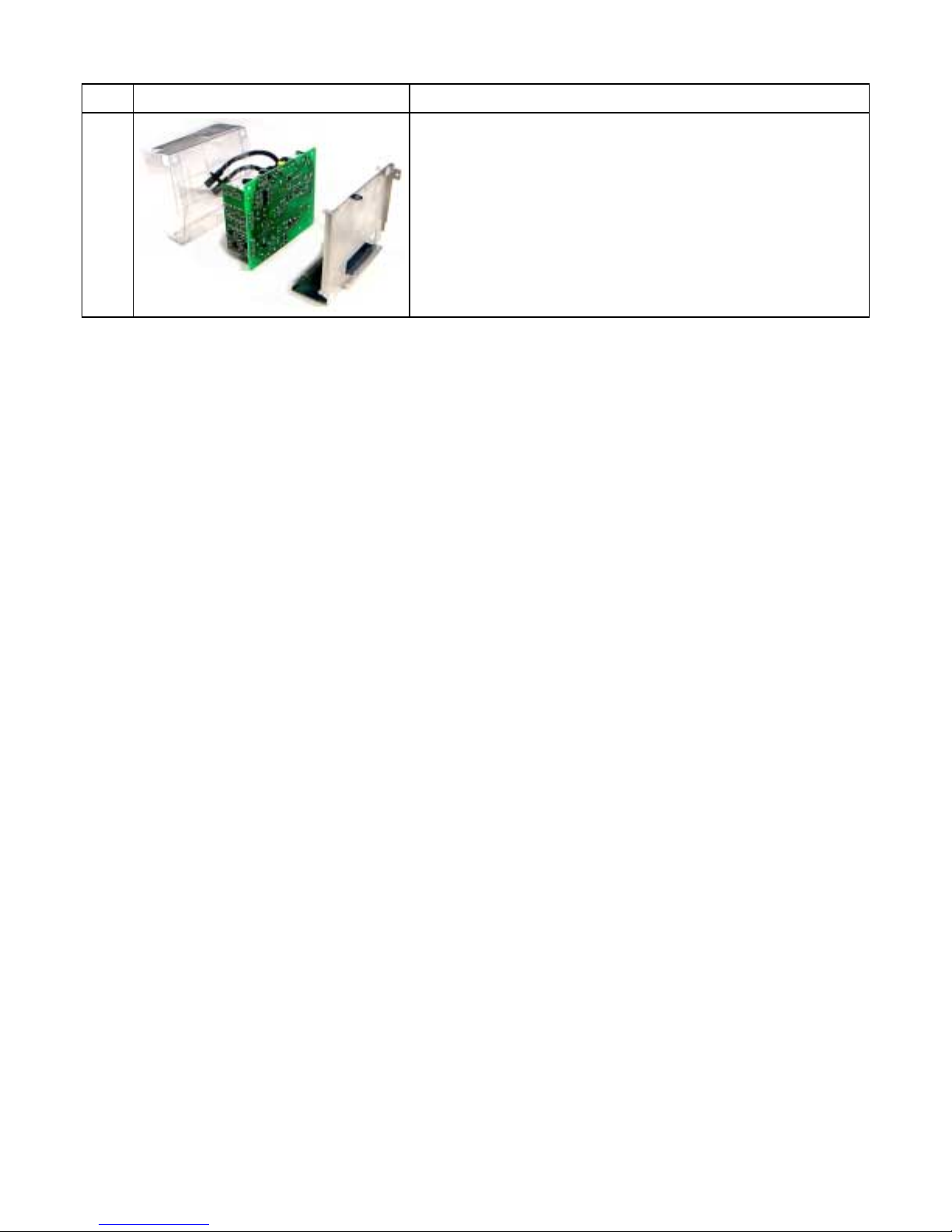
6-1. Extension cable kit ....................................... 2-7
7.
7-1. Main PCB ..................................................... 2-8
7-2. Drive PCB ................................................... 2-9
SECTION 3
PARTS LIST
2. PARTS LIST ........................................................ 3-8
0-3
EXPLANATION OF MAIN / DRIVE PC BOARD
..... 2-8
SAFETY PRECAUTIONS
RISK OF ELECTRIC SHOCK
DO NOT OPEN
CAUTION: TO REDUCE THE RISK OF
ELECTRIC SHOCK. DO NOT REMOVE
COVER (OR BACK). NO USER SERVICEABLE
PARTS INSIDE. REFER SERVICING TO
QUALIFIED SERVICE PERSONNEL.
The lightning flash with arrowhead
symbol, within an equilateral triangle,
is intended to alert the user to the
presence of uninsulated "dangerous
voltage" within the product's
enclosure that may be of sufficient
magnitude to constitute a risk of
electric shock to persons.
The exclamation point within an
equilateral triangle is intended to
alert the user to the presence of
important operating and
maintenance (servicing) instructions
in the literature accompanying the
appliance.
WARNING: TO REDUCE THE RISK OF FIRE OR ELECTRIC SHOCK, DO NOT EXPOSE THIS
CAUTION:
FCC Radio Frequency Interference Statement
Note: This equipment has been tested and found to comply with the limits for a Class A
WARNING: Changes or modifications made to this equipment, not expressly approved by
Notice: This Class A digital apparatus complies with Canadian ICES-003.
APPLIANCE TO RAIN OR MOISTURE. DANGEROUS HIGH VOLTAGES ARE
PRESENT INSIDETHE ENCLOSURE. DO NOT OPEN THE CABINET. REFER
SERVICING TO QUALIRED PERSONNEL ONLY.
Laser beam is emitted when the laser button of the remote control is pressed. Do not
look from the front of the remote control. Do not face toward a person or to a mirror.
digital device, pursuant to part 15 of the FCC Rules. These limits are designed to
provide reasonable protection against harmful interference when the equipment is
operated in a commercial environment. This equipment generates, uses, and can
radiates radio frequency energy and, if not installed and used in accordance with the
instruction manual, may cause harmful interference to radio communications.
Operation of this equipment in a residential area is likely to cause harmful interference
in which case the user will be required to correct the interference at his own expense.
Toshiba, or parties authorized by Toshiba, could void the user's authority to operate
the equipment.
Cet appareil numerique de la classe A est conforme a la norme NMB-003 du Canada.
IMPORTANT PRECAUTIONS
Save Original Packing Materials
The original shipping carton and packing materials will come in handy
if you ever have to ship your LCD projector. For maximum protection,
repack the set as it was originally packed at the factory.
Avoid Volatile Liquid
Do not use volatile liquids, such as an insect spray, near the unit.
Do not leave rubber or plastic products touching the unit for a long
time. They will mar the finish.
Moisture Condensation
Never operate this unit immediately after moving it from a cold
location to a warm location. When the unit is exposed to such a
change in temperature, moisture may condense on the crucial
internal parts. To prevent the unit from possible damage, do not use
the unit for at least 2 hours when there is an extreme or sudden
change in temperature.
In the spaces provided below, record the Model and Serial No. Iocated
at the bottom of your LCD projector.
Mode No. Serial No.
Retain this information for future reference.
0-4
IMPORTANT SAFETY INSTRUCTIONS
CAUTION: PLEASE READ AND OBSERVE ALL WARNINGS AND INSTRUCTIONS GIVEN IN OWNER'S
MANUAL AND THOSE MARKED ON THE UNIT. RETAIN THIS BOOKLET FOR FUTURE REFERENCE.
This set has been designed and manufactured to assure personal safety. Improper use can result in electric
shock or fire hazard. The safeguards incorporated in this unit will protect you if you observe the following
procedures for installation, use and servicing. This unit is fully transistorized and does not contain any par ts
that can be repaired by the user.
DO NOT REMOVE THE CABINET COVER, OR YOU MAY BE EXPOSED TO DANGEROUS VOLTAGE.
REFER SERVICING TO QUALIFIED SERVICE PERSONNEL ONLY.
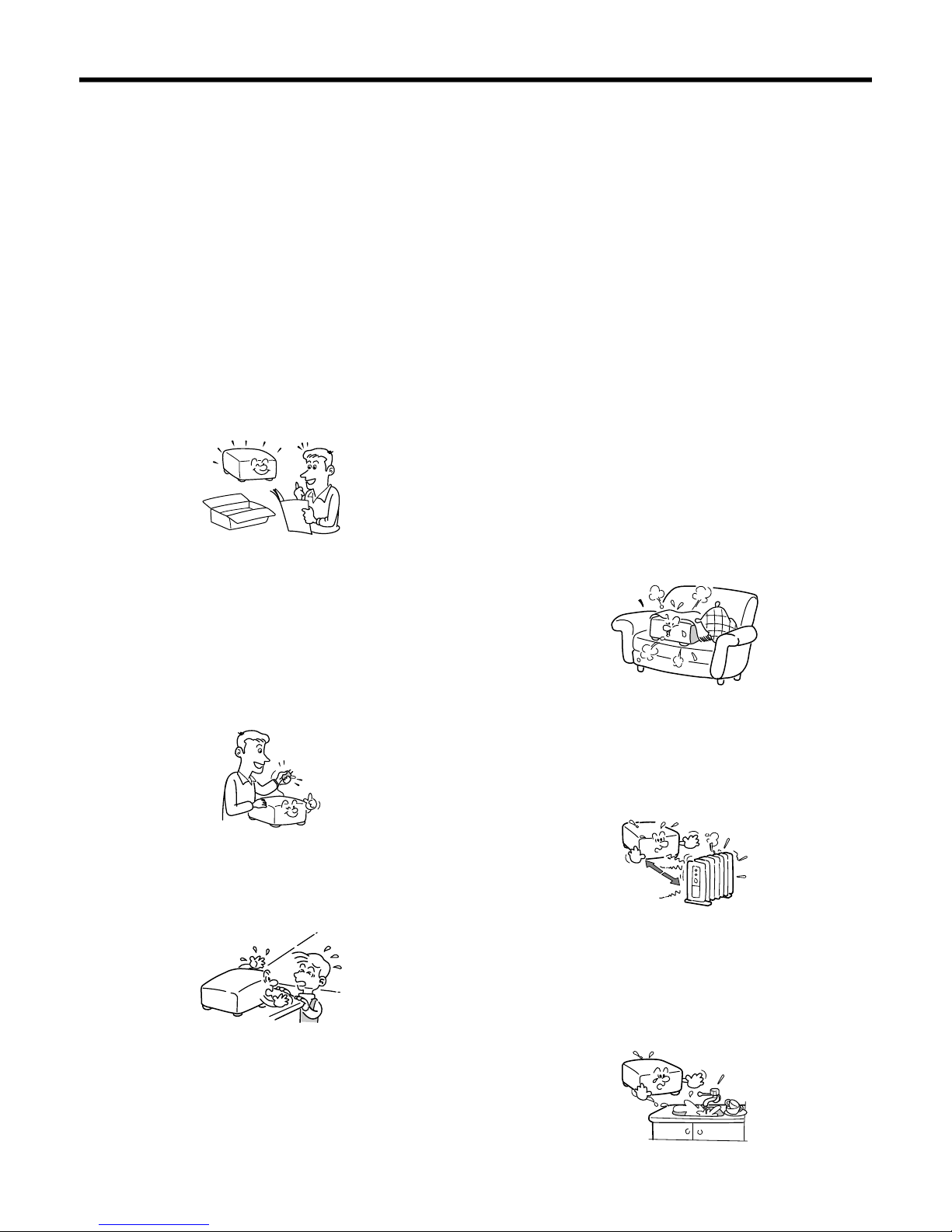
1. Read Owner's Manual
After unpacking this product, read the owner fs
manual carefully, and follow all the operating and
other instructions.
2. Power Sources
This product should be operated only from the
type of power source indicated on the marking
label. If you are not sure of the type of power
supply to your home, consult your product dealer
or local power company. For products intended to
operate from battery power, or other sources,
refer to the operating instructions.
4. V entilation
Openings in the cabinet are provided for
ventilation and to ensure reliable operation of the
product and to protect it from overheating, and
these openings must not be blocked or covered.
The openings should never be blocked by placing
the product on a bed, sofa, rug or other similar
surface. This product should not be placed in a
built-in installation such as a bookcase or rack
unless proper ventilation is provided or the
manufacturer fs instructions have been adhered
to.
5. Heat
The product should be situated away from heat
sources such as radiators, heat registers, stoves,
or other products (including amplifiers) that
produce heat.
3. Source of Light
Do not look into the lens while the lamp is on. The
strong light from the lamp may cause damage to
your eyes or sight.
6. Water and Moisture
Do not use this product near water – for example,
near a bath tub, wash bowl, kitchen sink, or
laundry tub; in a wet basement; or near a
swimming pool and the like.
0-5
IMPORTANT SAFETY INSTRUCTIONS (continued)
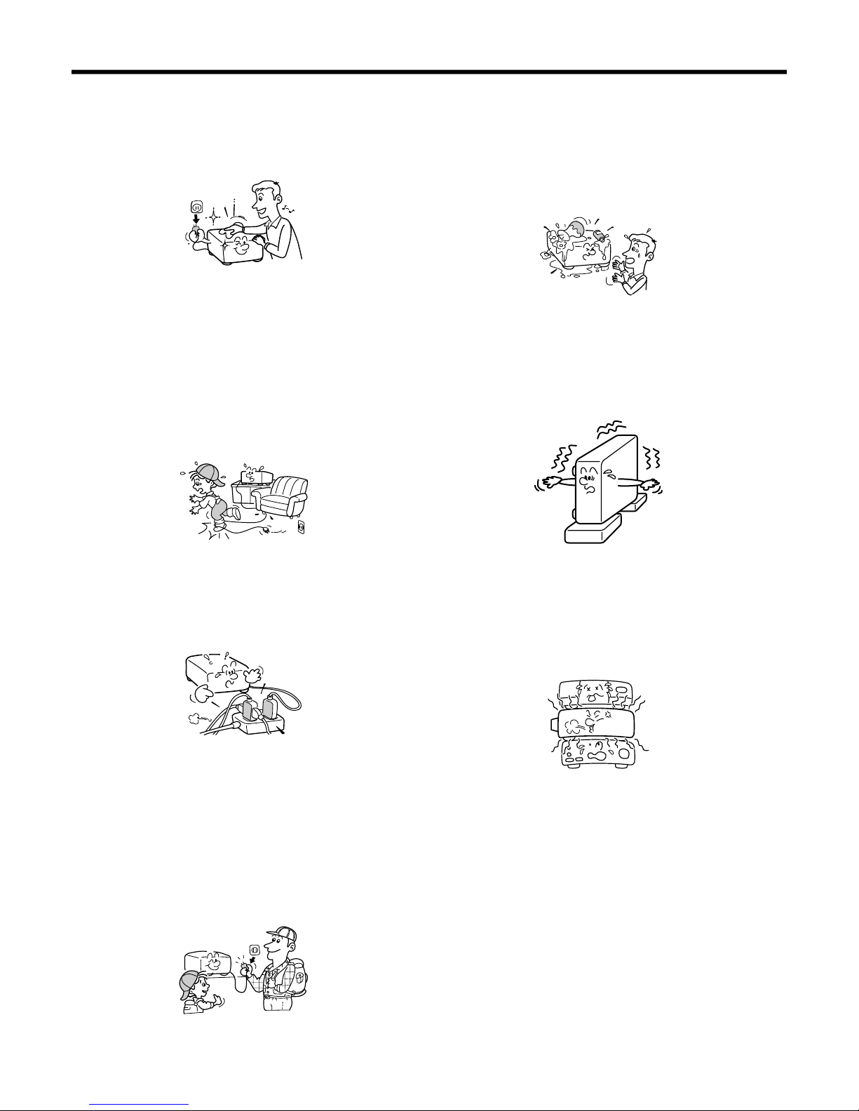
7. Cleaning
Unplug this product from the wall outlet before
cleaning. Do not use liquid cleaners or aerosol
cleaners. Use a damp cloth for cleaning.
8. Power-Cord Protection
Power-supply cords should be routed so that they
are not likely to be walked on or pinched by items
placed upon or against them, paying particular
attention to cords at plugs, convenience
receptacles, and the point where they exit from
the product.
11. Object and Liquid Entry
Never push objects of any kind into this product
through openings as they may touch dangerous
voltage points or short-out parts that could result
in a fire or electric shock. Never spill liquid of any
kind on the product.
12. Do not place the product vertically
Do not use the product in the upright position to
project the pictures at the ceiling, or any other
vertical positions. It may fall down and dangerous.
9. Overloading
Do not overload wall outlets; extension cords, or
integral convenience receptacles as this can
result in a risk of fire or electric shock.
10. Lightning
For added protection for this product during storm,
or when it is left unattended and unused for long
periods of time, unplug it from the wall outlet.
This will prevent damage to the product due to
lightning and power-line surges.
13. Stack Inhibited
Do not stack other equipment on this product or
do not place this product on the other equipment.
Top and bottom plates of this product develops
heat and may give some undesirable damage to
other unit.
14. Attachments
Do not use attachments not recommended by the
product manufacturer as they may cause hazards.
0-6
IMPORTANT SAFETY INSTRUCTIONS (continued)
15. Accessories
Do not place this product on an unstable cart,
stand, tripod, bracket, or table. The product may
fall, causing serious injury to a child or adult, and
serious damage to the product. Use only with a
cart, stand, tripod, bracket, or table recommended
by the manufacturer, or sold with the product.
Any mounting of the product should follow the
manufacturer fs instructions, and should use a
mounting accessory recommended by the
manufacturer. A product and cart combination
should be moved with care. Quick stops, excessive
force, and uneven surfaces may cause the product
and cart combination to overturn.
S3125A
16. If glass components, including lens and
lamp, should break, contact your dealer for
repair service.
This product incorporates glass components,
including a lens and a lamp. If such parts should
break, please handle with care to avoid injury and
contact your dealer for repair service. The broken
pieces of glass may cause to injury. In the
unlikely event of the lamp rupturing, thoroughly
clean the area around the projector and discard
18. Servicing
Do not attempt to service this product yourself as
opening or removing covers may expose you to
dangerous voltage or other hazards. Refer all
servicing to qualified service personnel.
19. Replacement Parts
When replacement parts are required, be sure the
service technician has used replacement parts
specified by the manufacturer or have the same
characteristics as the original part. Unauthorized
substitutions may result in fire, electric shock, or
other hazards. (Replacement of the lamp only
should be made by users.)
20. Safety Check
Upon completion of any service or repairs to this
product, ask the service technician to perform
safety checks to determine that the product is in
proper operating condition.
17. Damage Requiring Service
Unplug this product from the wall outlet and refer
servicing to qualified service personnel under the
following conditions:
a) When the power-supply cord or plug is
damaged.
b) If liquid has been spilled, or objects have fallen
into the product.
c) If the product has been exposed to rain or
water.
d) If the product does not operate normally by
following the operating instructions. Adjust only
those controls that are covered by the
operating instructions as an improper
adjustment of other controls may result in
damage and will often require extensive work
by a qualified technician to restore the product
to its normal operation.
e) If the product has been dropped or damaged in
any way.
f) When the product exhibits a distinct change in
performance – this indicates a need for service.
21. Do not get your hands between the camera
arm and the main unit when setting the
camera arm back in its original position.
To avoid injury, be careful not to get your hands
caught when setting the camera arm back in its
original position. Families with children should be
particularly careful.
22. Do not carry by the camera arm.
Do not carry the projector by the camera arm.
Doing so can result in damage or injury.
0-7
IMPORTANT SAFETY INSTRUCTIONS (continued)
23. Do not leave documents on the unit for long
periods of time while using the document
imaging function.
Do not leave texts, papers or other documents for
projection on the unit for long periods of time. The
heat could erase the letters on a thermal paper.
24. Do not move the projector while the arm is
still erect.
Always store the arm back in position when moving
the projector. Otherwise injury or damage may
result.
25. Do not look into the arm light while it is lit.
The strong light may cause damage to your eyes
or sight.
0-8
PART REPLACEMENT AND
ADJUSTMENT PROCEDURES
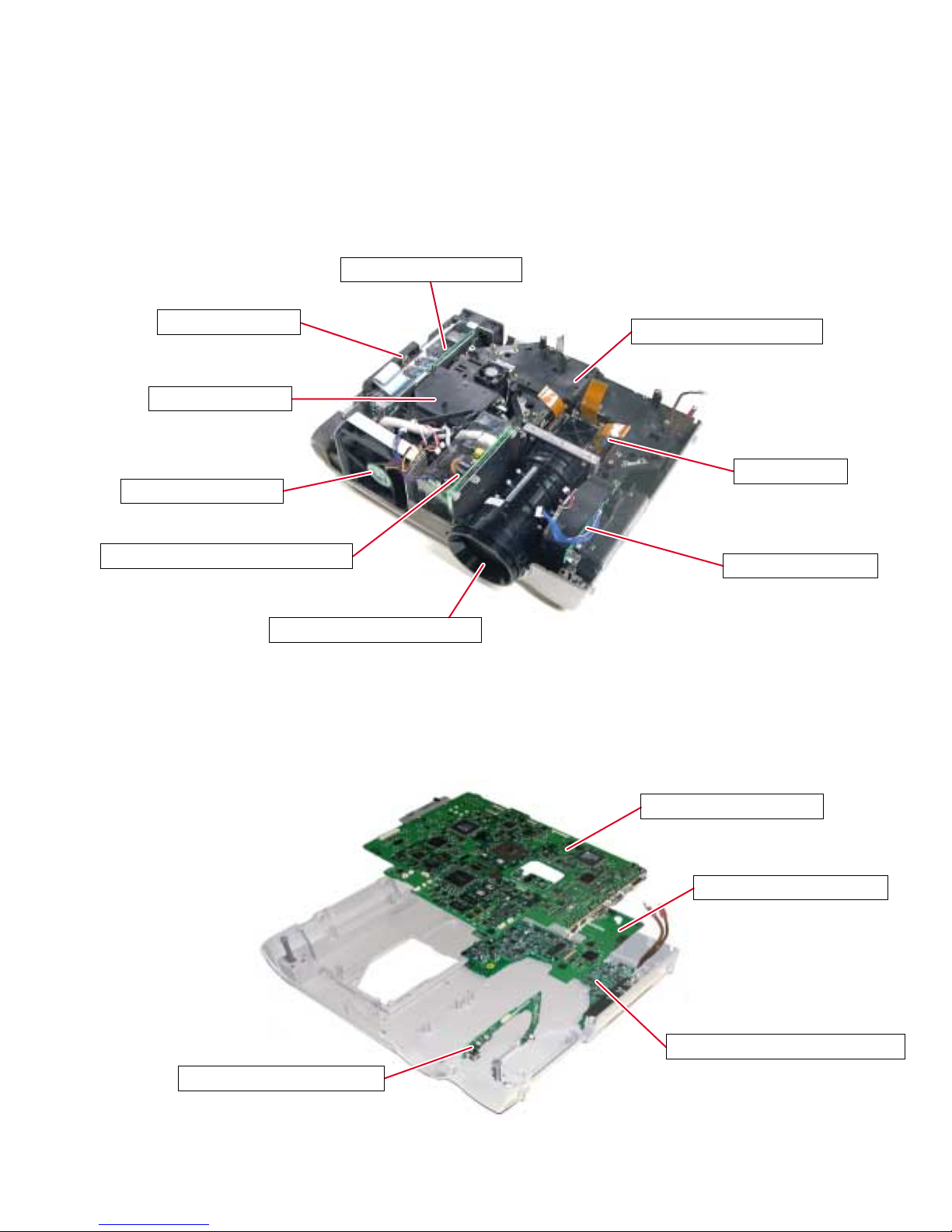
1. LOCATION OF MAIN PARTS
P800: POWER SUPPLY
SECTION 1
SPEAKER BLOCK
LAMP HOUSING
Z101: EXHAUST FAN
P850: BALLAST POWER SUPPLY
E201A: PROJECTION LENS
2. LOCATION OF PC BOARD
E201: OPTICAL ENGINE
LCD BLOCK
Z100: INTAKE FAN
E104: SENSOR PC BOARD
E101: MAIN PC BOARD
E102: DRIVE PC BOARD
E103: VIDEO/AUDIO PC BOARD
1-1
CAUTIONS BEFORE SERVICING
Electronic parts are susceptible to static electricity and may easily be damaged, so do not forget to take
proper grounding treatment as required.
Many screws are used inside the unit. To prevent missing, dropping, etc. of the screws, always use a
magnetized screwdriver in servicing. Several kinds of screws are used and some of them need special
cautions. That is, take care of the tapping screws securing molded parts and fine pitch screws used to
secure metal parts. If they are used improperly, the screw holes will be easily damaged and the parts can
not be fixed.
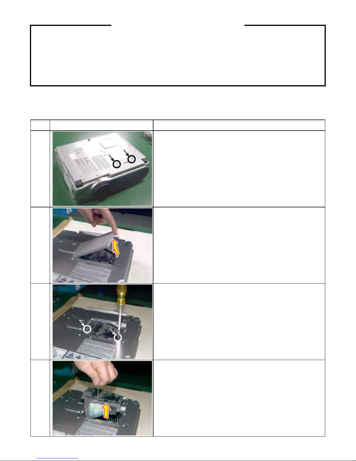
3. REPLACEMENT OF MECHANICAL PARTS
3-1. Lamp Assembly
Step Figure Explanation
Loosen 2 screws (M3 x 8).
These screws are retained with split washers.
1
2
3
Remove the lamp cover.
Loosen 2 screws that secure the lamp module (M3 x 8).
These screws are retained with split washers.
Lift the lamp module and slide out from the projector.
4
1-2
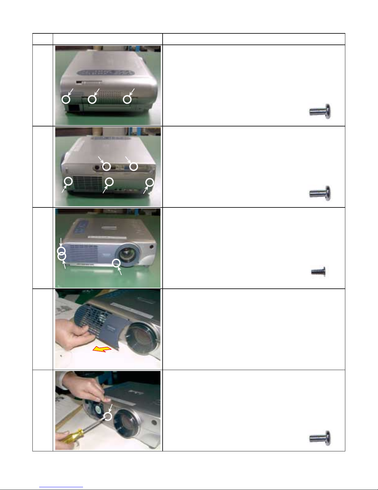
3-2. T op Cover
Step Figure Explanation
[Left Side]
Remove 3 screws (M3 x 6).
1
[Right Side]
Remove 5 screws (M3 x 6).
2
Screw : type [M-1]
Screw : type [M-1]
3
4
5
[Front]
Remove 3 screws (2 x 5).
Screw : type [M-2]
Remove front cover.
[Note]
Unsnap the bottom first, and then unsnap the top.
[Front]
Remove 1 screw (M3 x 6).
Screw : type [M-1]
1-3
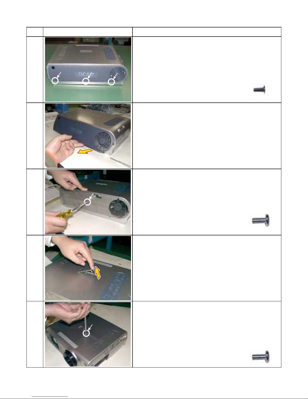
3-2. Top Cover (Continued)
Step Figure Explanation
[Rear]
Remove 3 screws (M2 x 5).
6
Remove rear cover.
[Note]
7
Unsnap the bottom first, and then unsnap the top.
Screw : type [M-2]
8
9
10
[Rear]
Remove 1 screw (M3 x 6).
Screw : type [M-1]
[Top]
Remove the small piece (One side is lifted and removed).
[Top]
Remove 1 screw (M3 x 6).
Screw : type [M-1]
1-4
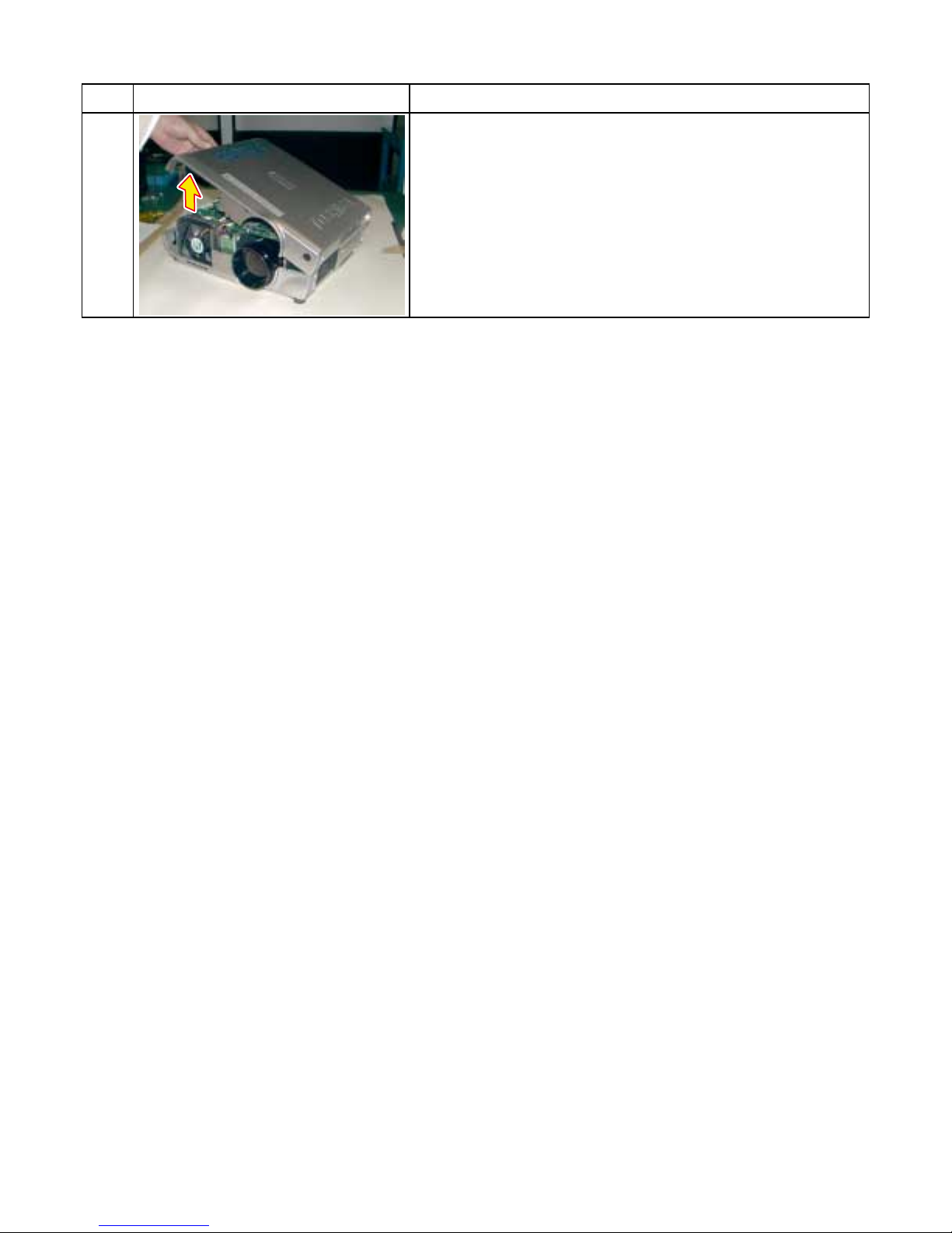
3-2. Top Cover (Continued)
Step Figure Explanation
Top cover can be removed by lifting left edge.
11
1-5
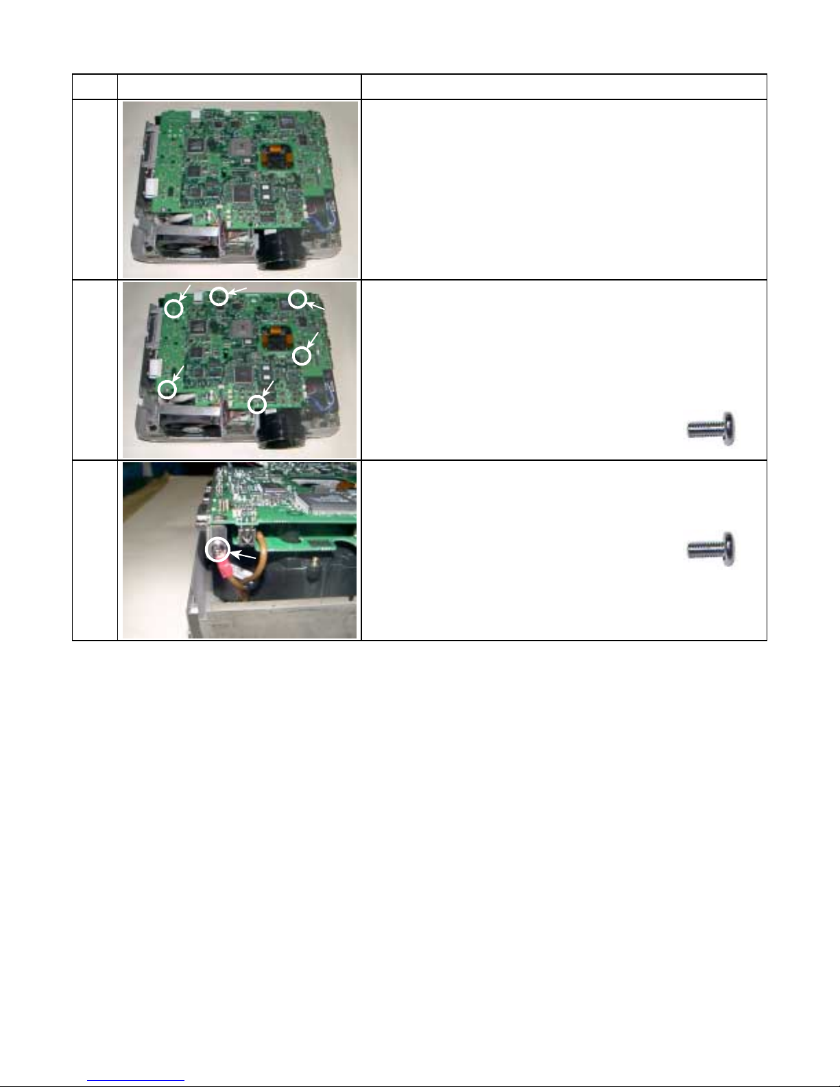
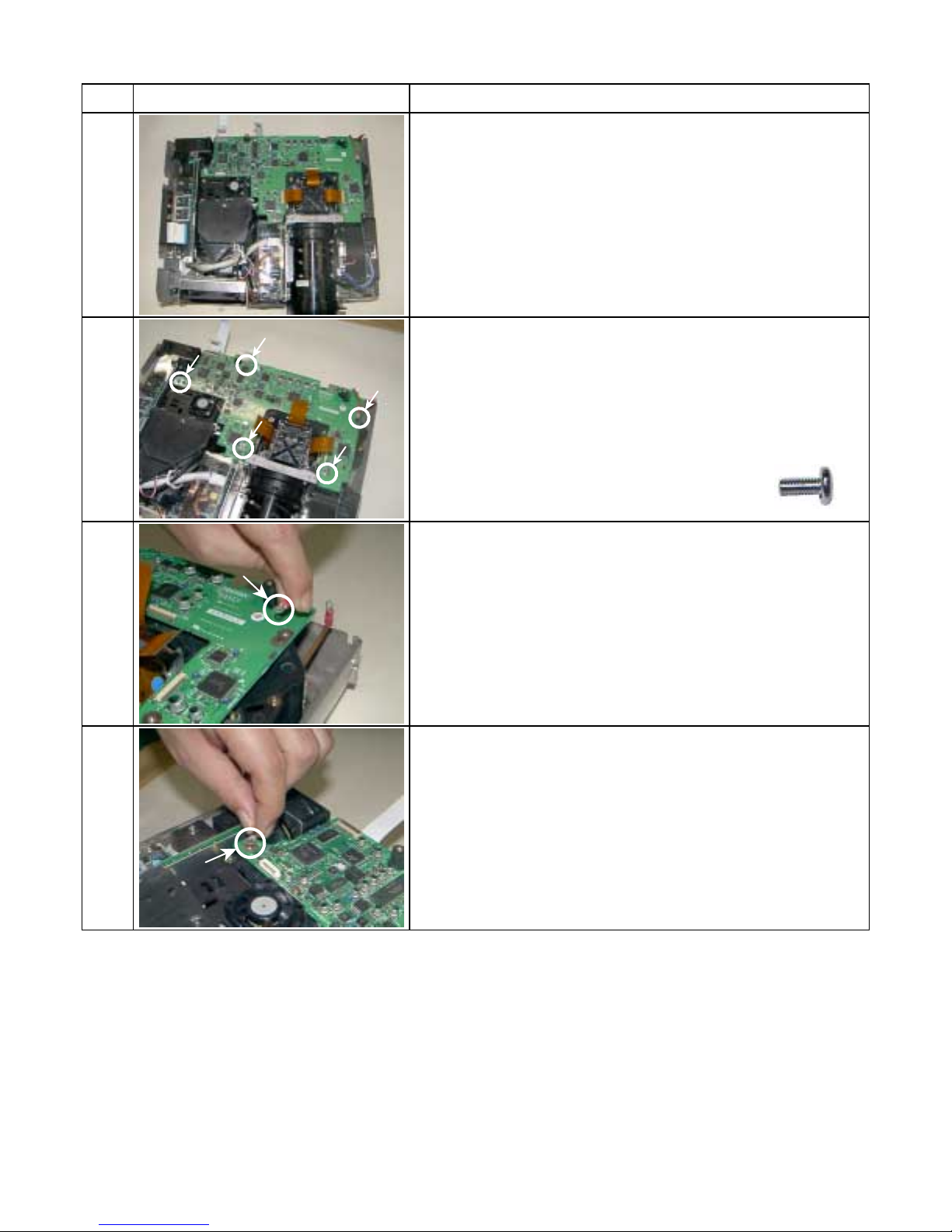
3-3. Main PC Board
Step Figure Explanation
Remove all cables and connectors.
1
Remove 6 screws (M3 x 6).
2
Screw : type [M-1]
3
Remove 1 screws (M3 x 6).
Screw : type [M-1]
[Note]
The screw here is also fixing the grand wire.
1-6
3-4. Drive PC Board
Step Figure Explanation
Remove all cables and connectors.
1
2
2a
2b
Remove 5 screws (M3 x 6).
2a2b2a
Screw : type [M-1]
[Note]
The screw here is also fixing the grand wire.
[Note]
The screw here is also fixing the grand wire.
2b
1-7
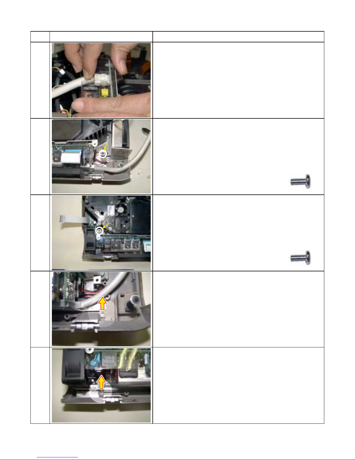
3-5. Power Supply
Step Figure Explanation
Disconnect the cable from the ballast power supply. (Plastic
case is opened)
1
Remove 1 screw (M3 x 8).
2
Screw : type [M-1]
3
4
Remove 1 screw (M3 x 8).
Screw : type [M-1]
Remove 1 hook from the bottom cabinet in the direction of
this arrow.
Remove 1 hook from the bottom cabinet in the direction of
this arrow.
5
1-8
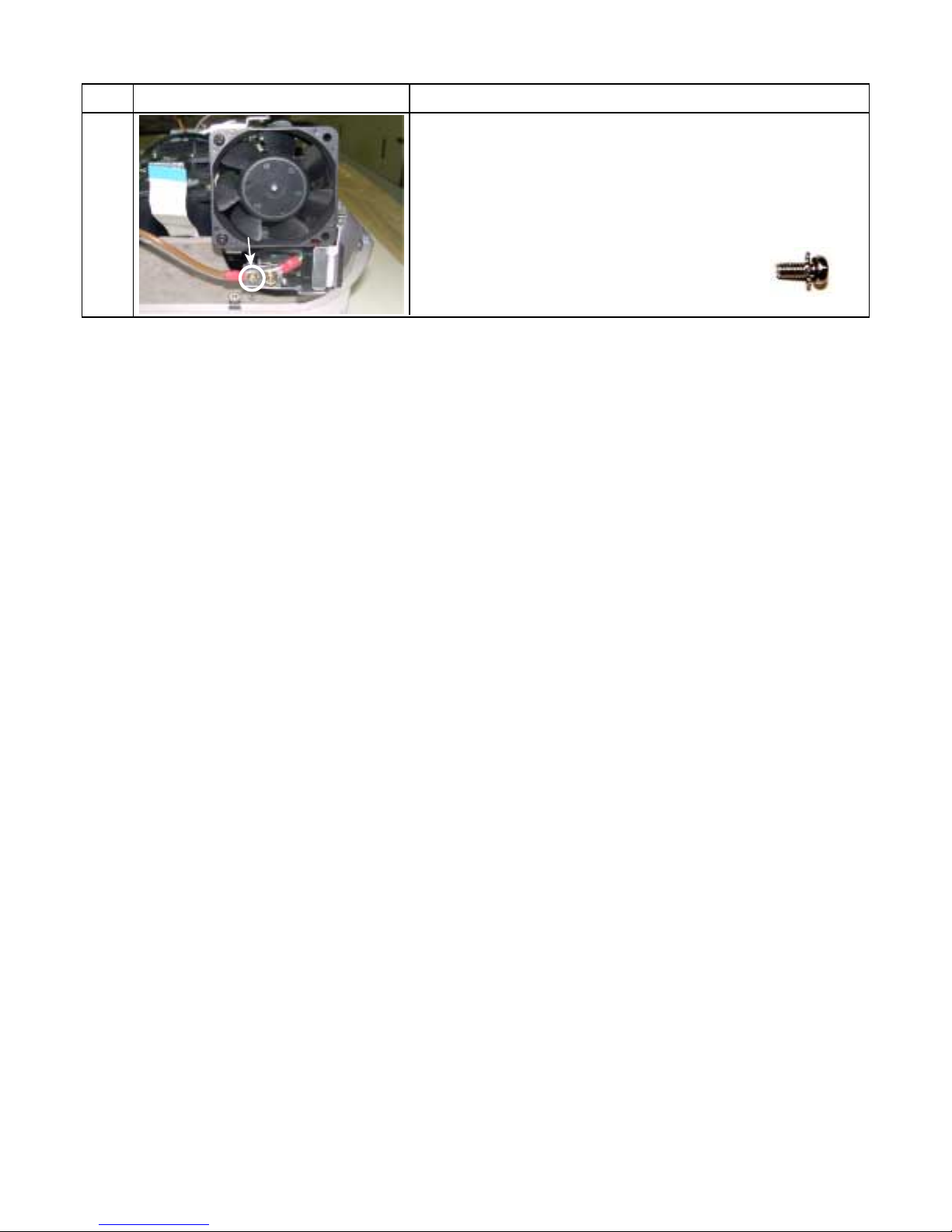
3-5. Power Supply (Continued)
Step Figure Explanation
Remove 1 screw (M3 x 6SW).
6
Screw : type [E-2]
1-9
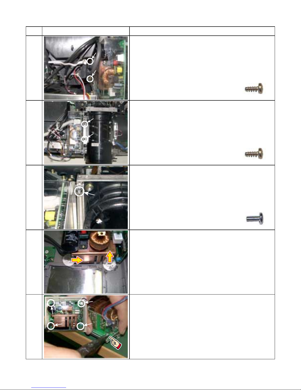
3-6. Ballast power Supply
Step Figure Explanation
Remove 2 screws (3 x 8), then, disconnect the lamp cable
connector.
1
Remove 2 screws (3 x 8).
2
Screw : type [M-3]
Screw : type [M-3]
3
4
(2)
(1)
Remove 1 screw (M3 x 6).
Screw : type [M-1]
Remove 2 hooks from the bottom cabinet in the direction of
this arrow. ( It removes in the order of (1)
Release 4 P.C. board holder by using tweezers.
→ (2). )
5
1-10
3-6. Ballast power Supply (Continued)
Step Figure Explanation
Remove the ballast power from the aluminum plate and
plastic case.
6
1-11
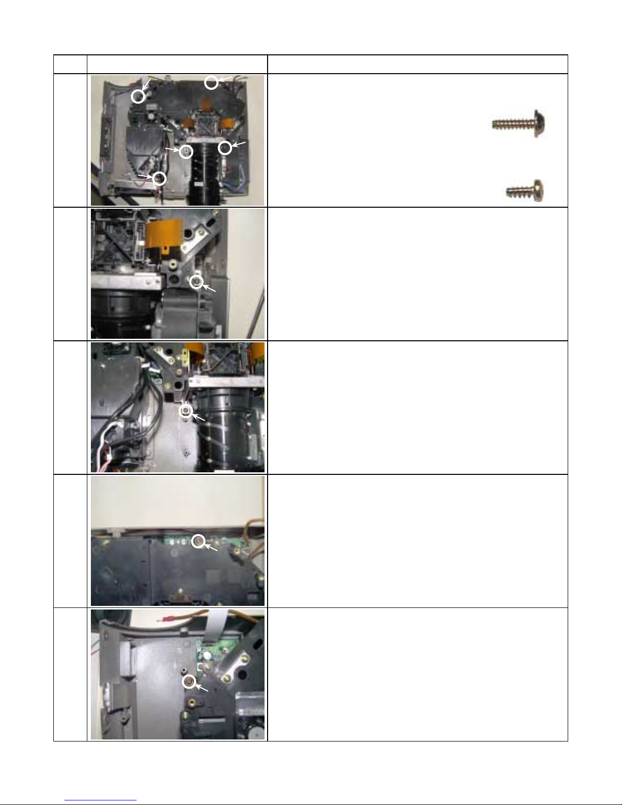
3-7. Optical Engine
Step Figure Explanation
1
1a
(d)
(e)
(c)
(b)
Remove 4 screws (3 x 12). .......(a)-(d)
Screw : type [M-4]
(a)
Remove 1 screw (3 x 8). ........(e)
Screw : type [M-3]
Enlargement (a)
Enlargement (b)
1b
1c
1d
Enlargement (c)
Enlargement (d)
1-12
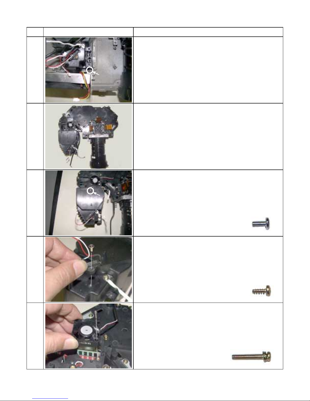
3-7. Optical Engine (Continued)
Step Figure Explanation
Enlargement (e)
[Note]
1e
This screw is different from others.
Whole engine appearance view.
2
3
4
Remove 1 screw and remove the lamp house (M3 x 6).
Screw : type [M-1]
Remove 1 screw and remove the thermal breaker (3 x 8).
Screw : type [M-3]
Remove 1 screw and remove the PBS cooling fan (M2.5 x
14SW).
5
Screw : type [E-9]
1-13
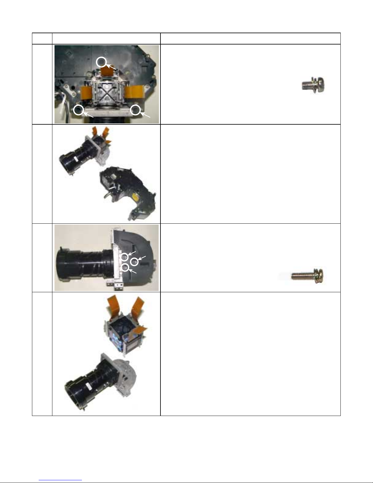
3-8. LCD Panel
Step Figure Explanation
1
2
(A)
Main frame
Sub frame
Remove 3 screws (M3 x 8SW) .
Screw : type [E-1]
[Note]
Tear off adhesive tape when you remove the screw of (A).
Separate the main frame and sub frame from the engine
block.
3
4
Bottom of main frame
Prism block
Main frame
Remove 3 screws (M3 x 12SW).
Screw : type [E-10]
Separate the prism block from the main frame.
1-14
 Loading...