

Page 1
Projector
TLP-SX3500
TLP-SX3500
User's Manual - Operating Guide
User's Manual - Operating Guide
Thank you for purchasing this projector.
WARNING Before using, first read the "Before using" section of this
manual. Then read other sections of this manual to ensure correct usage
through understanding. After reading, store them in a safe place for future
reference.
NOTE
• The manufacturer assumes no responsibility for any errors that may appear in this manual.
• The reproduction, transmission or use of this document or contents is not permitted without
express written authority.
TRADEMARK ACKNOWLEDGMENT :
• VGA and XGA are registered trademarks of the International Business Machines Corporation.
• Apple and Mac are registered trademarks of Apple Computer, Inc.
• VESA and SVGA are trademarks of the Video Electronics Standard Association.
• Windows is a registered trademark of Microsoft Corporation.
• Internet Explorer is a trademark of Microsoft Corporation.
All other trademarks are the property of their respective owners.
• The information in this manual is subject to change without notice.
1
Page 2

Before Using
Before Using
SAFETY PRECAUTIONS
The lightning flash with arrowhead symbol, within
an equilateral triangle, is intended to alert the user
to the presence of uninsulated "dangerous voltage"
within the product's enclosure that may be of
sufficient magnitude to constitute a risk of electric
shock to persons.
The exclamation point within an equilateral triangle
is intended to alert the user to the presence of
important operating and maintenance (servicing)
instructions in the literature accompanying the
appliance.
WARNING:TO REDUCE THE RISK OF FIRE OR ELECTRIC SHOCK, DO NOT EXPOSE
THIS APPLIANCE TO RAIN OR MOISTURE. DANGEROUS HIGH VOLTAGES
ARE PRESENT INSIDE THE ENCLOSURE. DO NOT OPEN THE CABINET.
REFER SERVICING TO QUALIFIED PERSONNEL ONLY.
2
Page 3
Before Using (continued)
Before Using (continued)
IMPORTANT SAFETY INSTRUCTIONS
CAUTION: PLEASE READ AND OBSERVE ALL WARNINGS AND
INSTRUCTIONS GIVEN IN THIS OWNER'S MANUAL AND THOSE
MARKED ON THE UNIT. RETAIN THIS BOOKLET FOR FUTURE
REFERENCE.
This set has been designed and manufactured to assure personal safety. Improper use
can result in electric shock or fire hazard. The safeguards incorporated in this unit will
protect you if you observe the following procedures for installation, use and servicing. This
unit is fully transistorized and does not contain any parts that can be repaired by the user.
DO NOT REMOVE THE CABINET COVER, OR YOU MAY BE EXPOSED TO
DANGEROUS VOLTAGE. REFER SERVICING TO QUALIFIED SERVICE
PERSONNEL ONLY.
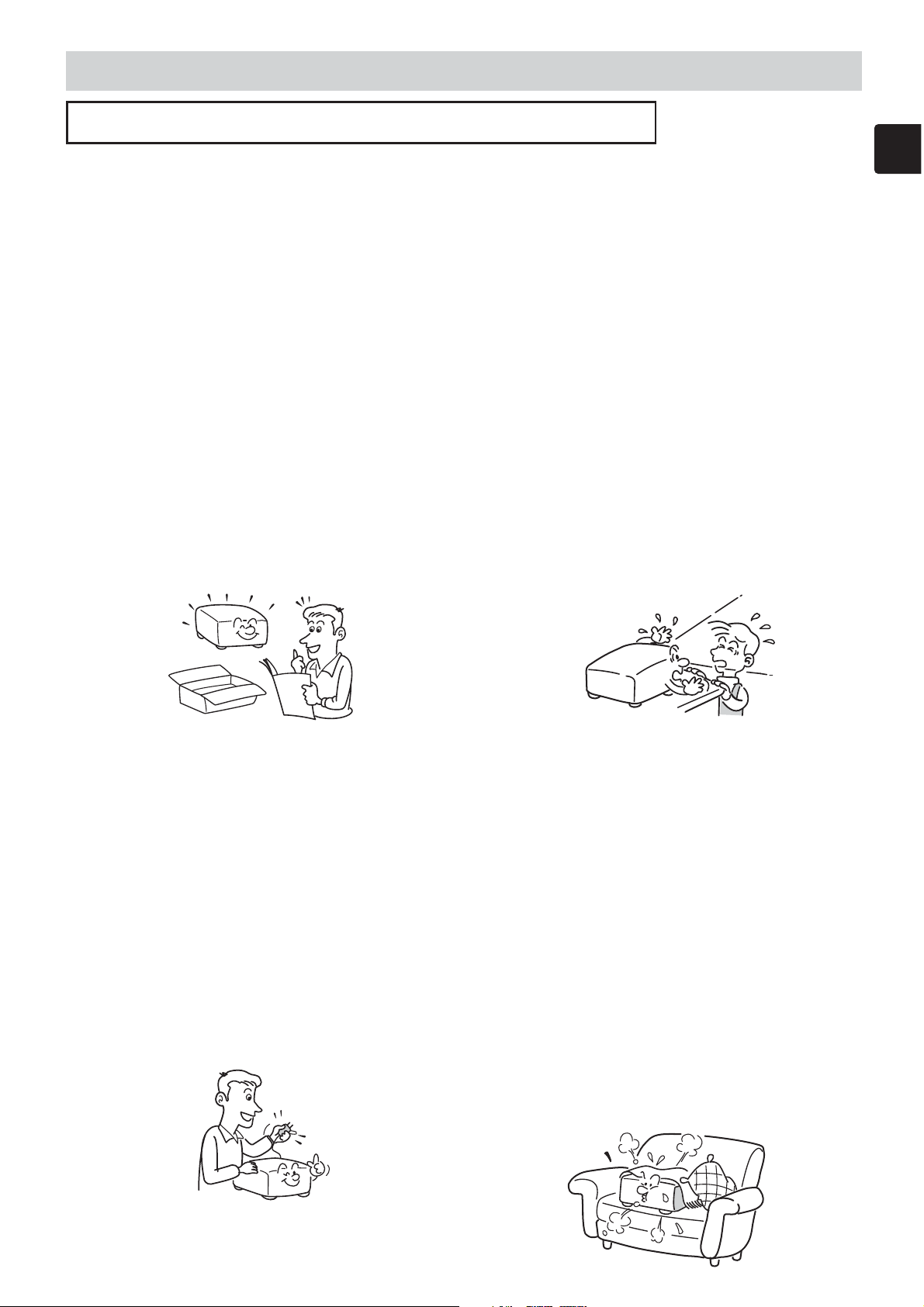
1. Read Owner's Manual
After unpacking this product, read
the owner's manual carefully, and
follow all the operating and other
instructions.
2. Power Sources
This product should be operated
only from the type of power source
indicated on the marking label. If
you are not sure of the type of
power supply to your home,
consult your product dealer or
local power company.
For products intended to operate
from battery power, or other
sources, refer to the operating
instructions.
3. Source of Light
Do not look into the lens while the
lamp is on. The strong light from
the lamp may cause damage to
your eyes or sight.
4. Ventilation
Openings in the cabinet are
provided for ventilation and to
ensure reliable operation of the
product and to protect it from
overheating, and these openings
must not be blocked or covered.
The openings should never be
blocked by placing the product on
a bed, sofa, rug or other similar
surface. This product should not
be placed in a built-in installation
such as a bookcase or rack unless
proper ventilation is provided or
the manufacturer's instructions
have been adhered to.
3
Page 4
Before Using (continued)
Before Using (continued)
IMPORTANT SAFETY INSTRUCTIONS (continued)
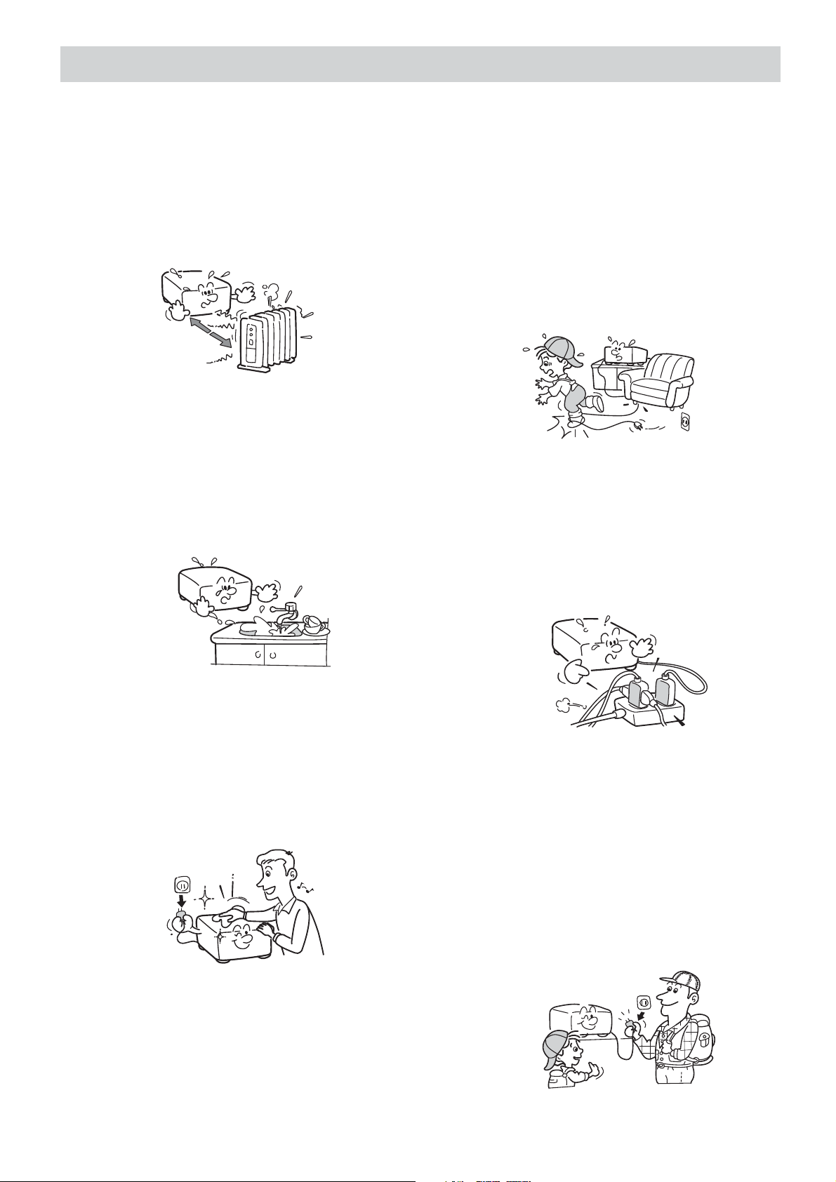
5. Heat
The product should be situated
away from heat sources such as
radiators, heat registers, stoves, or
other products (including
amplifiers) that produce heat.
6. Water and Moisture
Do not use this product near water.
- for example, near a bath tub,
wash bowl, kitchen sink, or
laundry tub; in a wet basement; or
near a swimming pool and the like.
8. Power-Cord Protection
Power-supply cords should be
routed so that they are not likely to
be walked on or pinched by items
placed upon or against them,
paying particular attention to
cords at plugs, convenience
receptacles, and the point where
they exit from the product.
9. Overloading
Do not overload wall outlets;
extension cords, or integral
convenience receptacles as this
can result in a risk of fire or
electric shock.
7. Cleaning
Unplug this product from the wall
outlet before cleaning. Do not use
liquid cleaners or aerosol
cleaners. Use a soft cloth for
cleaning.
10.Lightning storms
For added protection for this
product during storm, or when it is
left unattended and unused for
long periods of time, unplug it
from the wall outlet. This will
prevent damage to the product
due to lightning and power-line
surges.
4
Page 5
Before Using (continued)
Before Using (continued)
IMPORTANT SAFETY INSTRUCTIONS (continued)
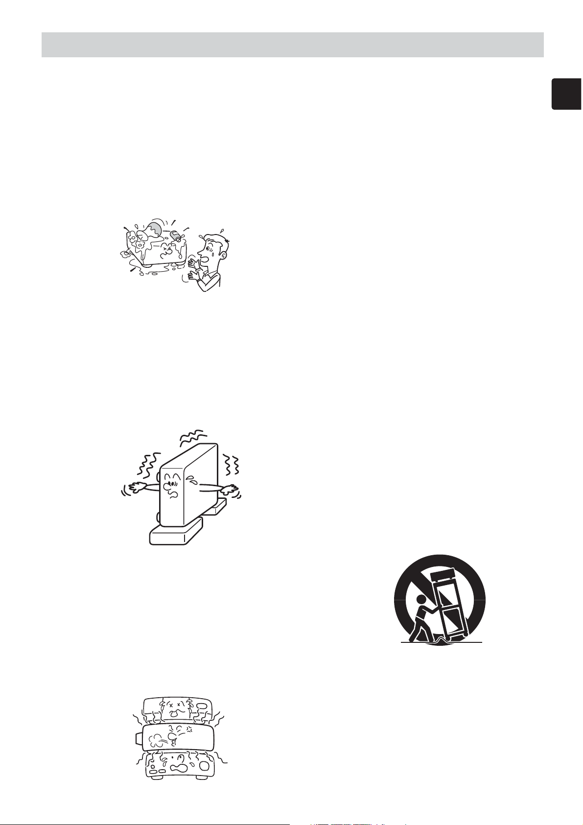
11. Object and Liquid Entry
Never push objects of any kind
into this product through openings
as they may touch dangerous
voltage points or short-out parts
that could result in a fire or electric
shock. Never spill liquid of any
kind on the product.
12.Do not place the product
vertically
Do not use the product in the
upright position to project the
pictures at the ceiling, or any other
vertical positions. It may fall down
and dangerous.
14.Attachments
Do not use attachments not
recommended by the product
manufacturer as they may cause
hazards.
15.Accessories
Do not place this product on an
unstable cart, stand, tripod,
bracket, or table. The product
may fall, causing serious injury to
a child or adult, and serious
damage to the product. Use only
with a cart, stand, tripod, bracket,
or table recommended by the
manufacturer, or sold with the
product. Any mounting of the
product should follow the
manufacturer's instructions, and
should use a mounting accessory
recommended by the
manufacturer. A product and cart
combination should be moved
with care. Quick stops, excessive
force, and uneven surfaces may
cause the product and cart
combination to overturn.
13.Stack Inhibited
Do not stack other equipment on
this product or do not place this
product on the other equipment.
Top and bottom plates of this
product develops heat and may
give some undesirable damage to
other unit.
S3125A
5
Page 6
Before Using (continued)
Before Using (continued)
IMPORTANT SAFETY INSTRUCTIONS (continued)
16.Damage Requiring Service
Unplug this product from the wall
outlet and refer servicing to
qualified service personnel under
the following conditions:
a) When the power-supply cord or
plug is damaged.
b) If liquid has been spilled, or
objects have fallen into the
product.
c) If the product has been exposed
to rain or water.
d) If the product does not operate
normally by following the
operating instructions. Adjust only
those controls that are covered by
the operating instructions as an
improper adjustment of other
controls may result in damage
and will often require extensive
work by a qualified technician to
restore the product to its normal
operation.
e) If the product has been dropped
or damaged in any way.
f) When the product exhibits a
distinct change in performance this indicates a need for service.
17.If glass components,
including lens and lamp,
should break, contact your
dealer for repair service.
This product incorporates glass
components, including a lens and
a lamp. If such parts should
break, please handle with care to
avoid injury and contact your
dealer for repair service. The
broken pieces of glass may cause
to injury. In the unlikely event of
the lamp rupturing, thoroughly
clean the area around the
projector and discard any edible
items placed in that area.
6
18.Servicing
Do not attempt to service this
product yourself as opening or
removing covers may expose you
to dangerous voltage or other
hazards. Refer all servicing to
qualified service personnel.
19.Replacement Parts
When replacement parts are
required, be sure the service
technician has used replacement
parts specified by the manufacturer
or have the same characteristics as
the original part. Unauthorized
substitutions may result in fire,
electric shock, or other hazards.
(Replacement of the lamp only
should be made by users.)
20.Safety Check
Upon completion of any service or
repairs to this product, ask the
service technician to perform safety
checks to determine that the product
is in proper operating condition.
21.
Do not leave thermal-paper
documents or easily
deformed items on top of the
unit or near the air exhaust.
The heat from the unit could erase
the information on the thermal paper,
or cause deformation or warping.
Also, when you touch a metal object
put near the air exhaust, a burn may
be caused.
Page 7
Before Using (continued)
Before Using (continued)
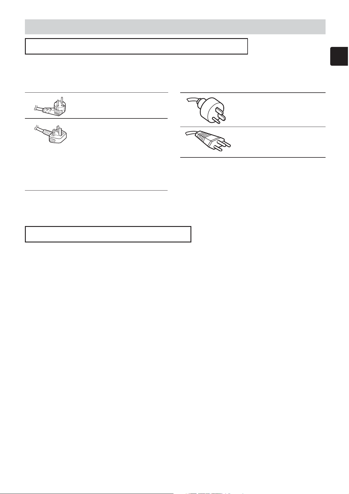
POWER SUPPLY CORD SELECTION
If your line voltage is 220 to 240V, use one of the following types of cable.
Plug
configuration
Use a 5A fuse which is approved by ASTA
or BSI to BSI362.
Always replace the fuse cover after
changing the fuse.
Plug type
EURO
UK
Line voltage
220 - 240V
220 - 240V
IMPORTANT PRECAUTIONS
Plug
configuration
Plug type
Australian
240V
10A
Switzerland
240V
6A
Line voltage
200 - 240V
200 - 240V
Save Original Packing Materials
The original shipping carton and packing materials will come in handy if you ever have
to ship your LCD projector. For maximum protection, repack the set as it was originally
packed at the factory.
Moisture Condensation
Never operate this unit immediately after moving it from a cold location to a warm
location. When the unit is exposed to such a change in temperature, moisture may
condense on the crucial internal parts. To prevent the unit from possible damage, do not
use the unit for at least 2 hours when there is an extreme or sudden change in
temperature.
Place and Manner of Installation
• Do not place in hot locations, such as near heating equipment. Doing so could cause
malfunction, and shorten the life of the LCD panel.
• Avoid locations with oil or cigarette smoke. Doing so will dirty the LCD panel and other
optical parts, shortening their lives, and darkening the screen.
• Do not use in angle of 20° or more degrees. Doing so could shorten the life of the
lamp.
• If used at high altitudes, the unit could cease operation even if used within the rated
temperature range. This is because the thinner air at high altitudes decreases the
internal cooling efficiency. Therefore, please lower the ambient temperature if using at
high altitudes.
7
Page 8

Before Using (continued)
Before Using (continued)
IMPORTANT PRECAUTIONS (continued)
Avoid Volatile Liquid
Do not use volatile liquids, such as an insect spray, near the unit. Do not leave rubber or
plastic products touching the unit for a long time. They will leave marks on the finish. If
cleaning with a chemically saturated cloth, be sure to follow the product's precautions.
LCD Panel
The life of the LCD panel is limited. Take care over the points below so as to use the
panel for years.
• To prolong the life of this panel, never fail to turn the power off when the panel is not in
use and make sure that the lamp has gone out. The state of the lamp being
extinguished helps enhance the effect of energy saving.
• If the air filter is stained and is clogged up, the main unit inner temperature rises. As a
result, the life of the LCD is shortened and a malfunction may also occur. Clean the air
filter from time to time and replace it regularly. It is recommended that this replacement
be done at the time of replacing a lamp. (Ask a dealer where the unit was purchased or
your nearby service station about an air filter for replacement.)
In the spaces provided below, record the Model and Serial No. located at the bottom of
your LCD projector.
Model No. Serial No.
Retain this information for future reference.
8
Page 9

Before Using (continued)
Before Using (continued)
EXEMPTION CLAUSES
• Toshiba Corporation bears no responsibility in the case of damages arising from natural
disaster such as earthquakes, lightning, etc., fire not liable to Toshiba Corporation,
operating by third parties, other accidents, or use under abnormal conditions including
erroneous or improper operation and other problems.
• Toshiba Corporation bears no responsibility for incidental damages (lost profit, work
interruption, corruption or loss of the memory contents, etc.) arising from the use of or
the inability to use this unit.
• Toshiba Corporation accepts no liability whatsoever for any damages arising from not
having followed the descriptions in this Instruction Manual.
• Toshiba Corporation accepts no liability whatsoever for any damages arising from
malfunctions arising from combination with equipment or software that is not related to
Toshiba Corporation.
OTHER CAUTIONS AND INFORMATIONS
Copyrights
Publicly showing or transmitting commercial imaging software or broadcast or Cablebroad casting programs, either commercially or collecting a fee from the audience, or
modifying images using the freeze or resize functions, could violate the direct or indirect
copyrights of the imaging software or broadcast program, etc., if done without first
consulting with the copyright holder. For this reason, please take appropriate measures
before performing one of the actions listed above, including obtaining a license from the
copyright holder.
Disposal
This product contains substances which are harmful to humans and the environment.
• The solder used in the PCB manufacturing process contains lead.
• The lamp contains inorganic mercury.
Please dispose of this product or used lamps in accordance with local regulations.
9
Page 10

Projector Features
Projector Features
This multimedia projector is used to project various computer signals as well as
NTSC/PAL/SECAM video signals onto a screen. Little space is required for
installation and large images can easily be realized.
Ultra High Brightness
●
Crisp, ultra-bright presentations is achieved by using an ultra high brightness lamp and a highly
efficient optical system.
Whisper Mode Equipped
●
Special mode is available for reducing projector noise to achieve quieter operation.
User Memory Function
●
This projector can memorize 4 settings by MY MEMORY function.
Partial Magnification Function
●
Interesting parts of images can be magnified for closer viewing.
Keystone Distortion Correction
●
Quick correction of distorted images electrically.
Optical Lens Shift
●
The lens of this projector can be shifted vertically. When you want to finely adjust the picture position,
use the LENS SHIFT buttons.
Preparation
Preparation
Please see the “Contents Of Package” of the “User’s Manual – Quick Guide”.
Your projector should come with the items shown there. Contact your dealer
anything is missing.
NOTE
sure to use the original packing material. Use special caution for the lens part.
• Keep the original packing material for future reshipment. For moving the projector, be
10
Page 11

Contents
………………………
………………
…………………………
…………………………
…………………………
……………………
……………………
…………………………
…………
………………
………………………………
……………………………
…………………………
…………………
……
……………………
Contents
Before Using
SAFETY PRECAUTIONS ………2
IMPORTANT SAFETY
INSTRUCTIONS …………………3
POWER SUPPLY CORD
SELECTION ………………………7
IMPORTANT PRECAUTIONS …7
EXEMPTION CLAUSES …………9
OTHER CAUTIONS AND
INFORMATIONS …………………9
Projector Features
Preparation
Part Names
Projector …………………………12
Control Buttons …………………13
Remote control……………………13
Setting Up
Arrangement………………………14
Adjusting The Projector’s
Elevator……………………………15
Using The Lens shift Buttons …15
Connecting Your Devices ………16
Connecting The Power Supply …19
Remote Control
About The Laser Pointer ………20
Loading Batteries ………………20
Operating The
Remote Control …………………21
Using The Remote
ID Feature…………………………21
Using The Mouse/Keyboard
Control Function …………………22
Power ON/OFF
Turning On The Power …………23
Turning Off The Power …………23
Operating
Selecting An Input Signal ………24
Selecting The Aspect Ratio ……25
10
10
12
14
20
23
24
2
Correcting The Keystone
Distortion …………………………26
Adjusting The Volume …………27
Muting The Sound ………………27
Temporarily Blanking
The Screen ………………………27
Freezing The Screen ……………28
Using The Magnify Feature ……28
Displaying The Child Window …29
Selecting An Audio Input ………29
Multifunctional Settings
Using The Menu Functions ……30
MAIN Menu ………………………31
PICTURE-1 Menu ………………32
PICTURE-2 Menu ………………34
INPUT Menu………………………35
AUTO Menu ………………………37
SCREEN Menu …………………39
OPTION Menu ……………………41
NETWORK Menu ………………43
Network Setting Up
Lamp
Replacing The Lamp ……………46
Air Filter
Caring For The Air Filter…………47
Other Care
Caring For The Inside Of
The Projector ……………………48
Caring For The Lens ……………48
Caring For The Cabinet And
Remote Control …………………48
Troubleshooting
Related Messages ………………49
Regarding The Indicator Lamps
Phenomena That May Easily Be
Mistaken For Machine Defects …53
Warranty And After-Service
Specifications
30
44
45
47
48
49
…51
55
55
Using The Automatic
Adjustment Feature………………25
Adjusting The Picture Position …26
TECHNICAL
11
Page 12
Part Names
Part Names
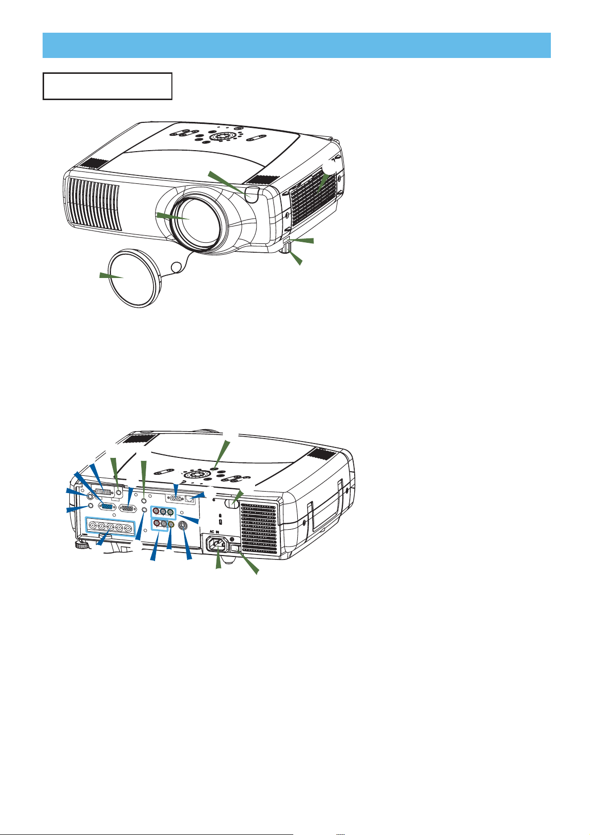
Projector
5
4
Projector (Front/Right)
LAMP
P
TEM
ANDBY/ON
ST
EO
U
EN
M
O
O
Z
US
M
FOC
ESET
R
NPUT
I
SEARCH
ONE
T
EYS
K
VID
O
E
VID
S-
TER
IN
T
EN
PON
COM
G
BN
T
IF
RGB
H
S
NS
E
M1-D
L
1 Elevator button
2 Elevator foot
3
6
3 Remote sensor
4 Lens cap
5 Lens
The picture is projected from
here.
1
6 Filter cover
An air filter is inside.
2
D
E
A
B
AUDIO IN1
AUDIO IN2
R/C
R
/P
R
C
8
RGB
G/Y
A RGB port
B M1-D port
-
7
L
REM
RGB OUT
B/C
B
/P
B
H
V
BNC
OTE CO
AUDIO OUT
LENS SHIFT
C
O
MP
O
N
S
-VID
EO
VID
EO
STANDBY/ON
F
CONTRO
NTROL
C
R
/P
R
R-AUDIO IN-L
L
C
B
/P
B
Y
VIDEO
S-VIDEO
M
I
H
B
EN
T
NETWORK
J
KEYSTONE
M
1
-D
RGB
SEARCH
IN
PU
T
NG
RESET
IN
T
ER
T
EM
P
L
A
M
G
FOCUS
MENU
P
ZOOM
3
K
09
C BNC port
D
AUDIO IN 1 port
E AUDIO IN 2 port
F CONTROL port
G NETWORK port
H AUDIO IN R/L port
I VIDEO IN port
J S-VIDEO port
K COMPONENT port
L RGB OUT port
M AUDIO OUT port
Projector (Rear/Left)
7 REMOTE CONTROL port
8 DC OUT port
9 AC Inlet
0 Power switch
- Control buttons
See the following page.
12
Page 13
Part Names (continued)
1
e
w q
4
7
8
9
0
=
2
5
6
t
y
u
3
r
Part Names (continued)
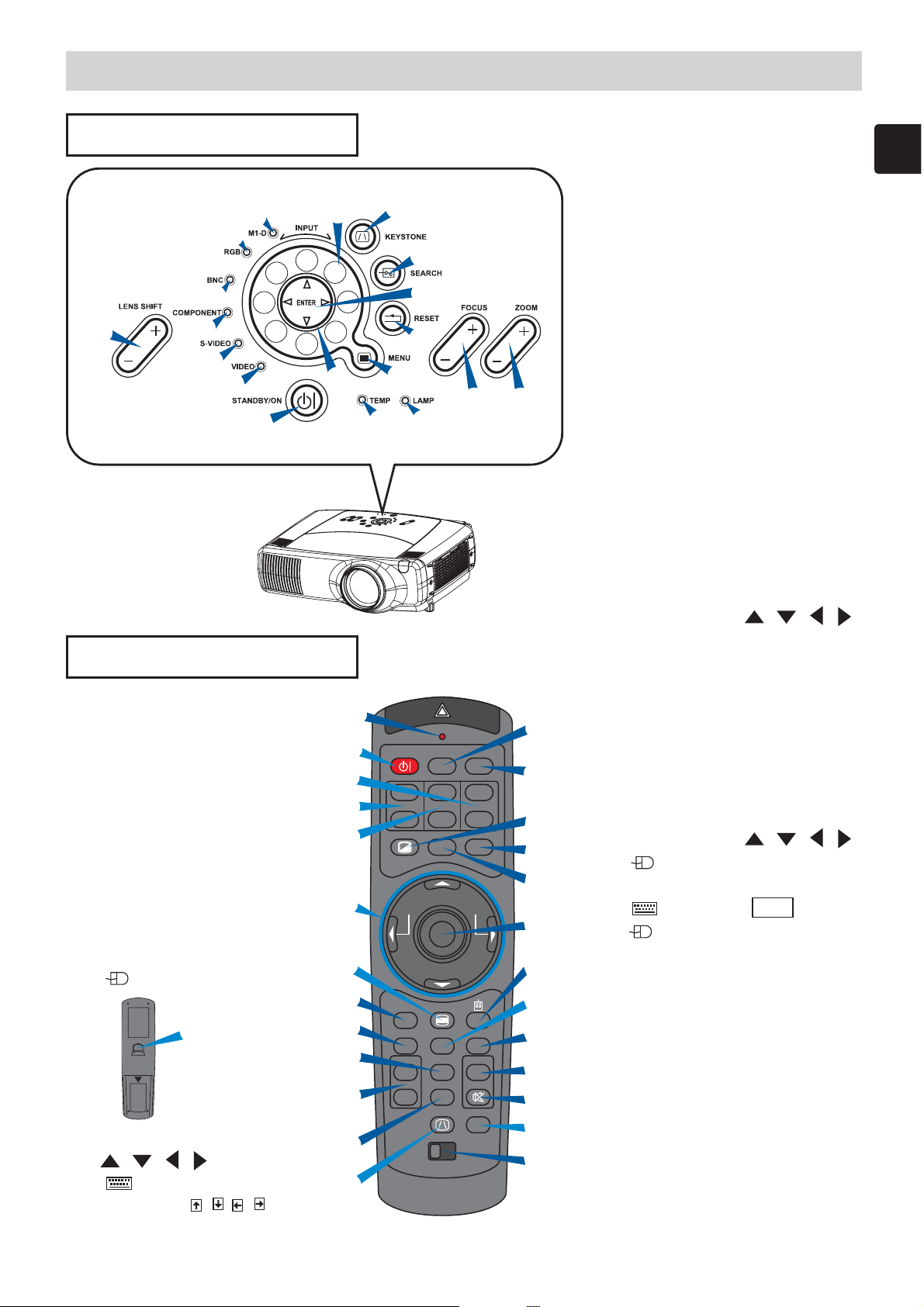
Control Buttons
P
M
LA
P
M
E
T
N
O
/
ANDBY
ST
O
E
ID
V
U
N
E
M
O
DE
I
V
S
R
M
E
T
O
N
I
O
Z
S
FOCU
T
T
E
N
S
E
E
N
R
O
P
OM
C
G
N
B
T
U
P
N
I
H
C
B
T
R
F
RG
SHI
SEA
NS
LE
D
1
M
E
N
TO
S
EY
K
Control Panel
on the Projector
1 STANDBY/ON button
and STANDBY/ON indicator
2 TEMP indicator
3 LAMP indicator
4 LENS SHIFT buttons
5 INPUT dial
6 SEARCH button
7 M1-D indicator
8 RGB indicator
9 BNC indicator
0 COMPONENT indicator
- S-VIDEO indicator
= VIDEO indicator
q ZOOM buttons
w FOCUS buttons
e KEYSTONE button
r MENU button
t RESET button
y ENTER button
u Cursor buttons / / /
Remote Control
1 STANDBY/ON button
4 LENS SHIFT buttons
6 SEARCH button
q ZOOM buttons
w FOCUS buttons
e KEYSTONE button
r MENU button
t RESET button
y ENTER button
( Mouse left button)
y
(Rear)
u Cursor buttons
///
( Keyboard
Arrow keys / / / )
i
1
q
4
w
u
LASER INDICATOR
STANDBY/ON
VIDEO
+
LENS SHIFT
FOCUS ZOOM
–––
ASPECT
BLANK
PREVIOUS
MOUSE
r
s
f
h
j
ESC MENU
POSITION
MAGNFY
ON
FREEZE MUTE
OFF
KEYSTONE
RESET AUTO
1 2 3
k
ID CHANGE
e
Remote Control
RGB
++
LASER
NEXT
PinP
VOLUME
SEARCH
o
p
[
\
]
a
d
t
g
l
;
6
'
i LASER INDICATOR
o VIDEO button
p RGB button
[ BLANK button
] ASPECT button
\ LASER button
a Cursor buttons / / /
( Mouse move pointer)
s ESC button
( Keyboard ESC key)
d ( Mouse right button)
f POSITION button
g AUTO button
h PinP button
j MAGNIFY buttons
k FREEZE button
l VOLUME button
; MUTE button
' ID CHANGE switch
13
Page 14
Setting Up
D
B
C
A
B
D
B
C
A
B
Setting Up
Arrangement
WARNING • Before installation, make sure that the projector is turned off and the
power code is disconnected.
• Do not set up and move the projector, while it is hot.
• Install the projector in a suitable environment according to instructions of this manual.
• The power outlet should be close to the projector and easily accessible.
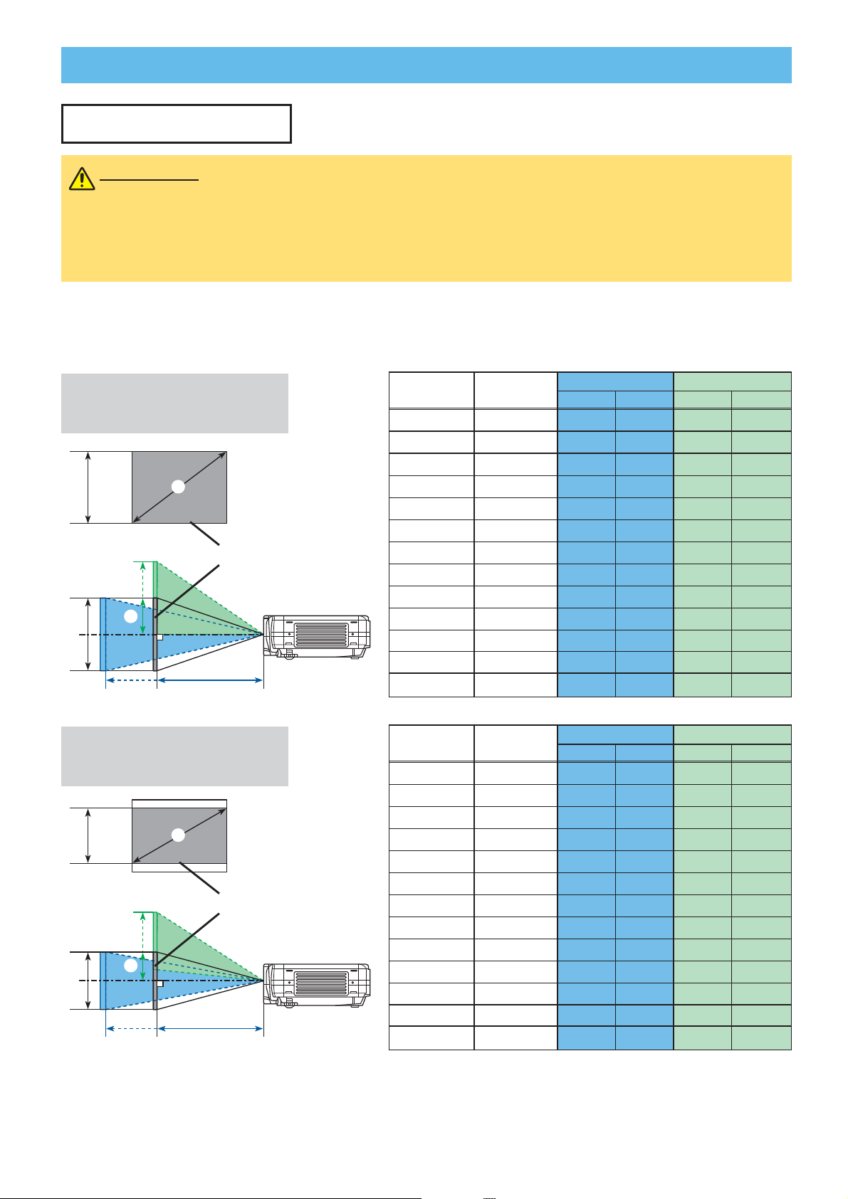
Refer to the illustrations and tables below to determine the screen size and projection
distance. The values shown in the table are calculated for a full size screen. (±10%)
Reference for
the 4:3 aspect ratio
Screen
Reference for
the 16:9 aspect ratio
Screen
Side view
Side view
A
[inch (m)]B[inch (cm)]
40(1.0) 24(61)
60(1.5) 36(91)
70(1.8) 42(107)
80(2.0) 48(122)
100(2.5) 60(152)
120(3.0) 72(183)
150(3.8) 90(229)
200(5.1) 120(305)
250(6.4) 150(381)
300(7.6) 180(457)
350(8.9) 210(533)
400(10.2) 240(610)
500(12.7) 300(762)
A
[inch (m)]B[inch (cm)]
40(1.0) 20(50)
60(1.5) 29(75)
70(1.8) 34(87)
80(2.0) 39(100)
100(2.5) 49(125)
120(3.0) 59(149)
150(3.8) 74(187)
200(5.1) 98(249)
250(6.4) 123(311)
300(7.6) 147(374)
350(8.9) 172(436)
400(10.2) 196(498)
450(11.4) 221(560)
C [inch (m)] D [inch (cm)]
min. max. min. max.
46(1.2) 71(1.8) 12(30) 24(61)
71(1.8) 107(2.7) 18(46) 36(91)
83(2.1) 126(3.2) 21(53) 42(107)
95(2.4) 144(3.7) 24(61) 48(122)
120(3.0) 181(4.6) 30(76) 60(152)
144(3.7) 217(5.5) 36(91) 72(183)
181(4.6) 272(6.9) 45(114) 90(229)
243(6.2) 364(9.2) 60(152) 120(305)
304(7.7)
366(9.3)
427(10.9) 638(16.2)
489(12.4) 730(18.5)
612(15.5) 913(23.2)
min. max. min. max.
50(1.3) 77(2.0) 10(25) 23(58)
77(2.0) 117(3.0) 15(37) 34(87)
91(2.3) 137(3.5) 17(44) 40(102)
104(2.6) 157(4.0) 20(50) 46(116)
131(3.3) 197(5.0) 25(62) 57(145)
158(4.0) 237(6.0) 29(75) 69(174)
198(5.0) 297(7.5) 37(93) 86(218)
265(6.7)
332(8.4)
399(10.1) 596(15.1)
466(11.8) 696(17.7)
533(13.5) 795(20.2)
600(15.2) 895(22.7)
455(11.6)
547(13.9)
C [inch (m)] D [inch (cm)]
396(10.1)
496(12.6)
75(191) 150(381)
90(229) 180(457)
105(267) 210(533)
120(305) 240(610)
150(381) 300(762)
49(125) 114(291)
61(156) 143(363)
74(187) 172(436)
86(218) 200(508)
98(249) 229(581)
110(280) 257(654)
14
Page 15
I
N
T
E
R
I
N
P
U
T
M
1
-
D
R
G
B
BN
G
S-
V
I
D
E
O
STA
N
D
BY
/
O
N
T
E
M
P
VI
DE
O
C
O
M
P
O
N
E
N
T
L
A
MP
K
E
Y
STO
N
E
S
EA
R
C
H
R
E
SE
T
M
E
N
U
F
O
C
U
S
L
E
N
S
S
H
I
F
T
Z
O
O
M
Setting Up (continued)
STANDBY/ON
VIDEO
LASER INDICATOR
RGB
BLANK ASPECT LASER
LENS SHIFT
+
–––
++
FOCUS ZOOM
Setting Up (continued)
Adjusting The Projector's Elevator
WARNING • Do not touch about the lens and ventilation openings during use or
immediately after use to prevent a burn.
•
CAUTION
it backward or forward exceeding 9 degrees. Exceeding these range could cause
malfunction, and could shorten the lifetime of the consumables.
• To prevent damaging the projector and injuring yourself, always hold the projector
whenever using the elevator buttons to adjust the elevator feet.
You can use the elevator feet to make adjustments if the surface on which you need to set
the projector is uneven or if you otherwise need to adjust the angle of projection. The
adjustment range of the elevator feet is 0 to 9 degrees.
Do not incline the projector rightward or leftward. Also do not incline
Press and hold in the elevator buttons.
1
Raise or lower the projector to the desired height and
2
then release the elevator buttons.
When you release the elevator buttons, the elevator
feet will lock into position.
As necessary, you can also finely adjust the height of
3
the projector by twisting the elevator feet by hand.
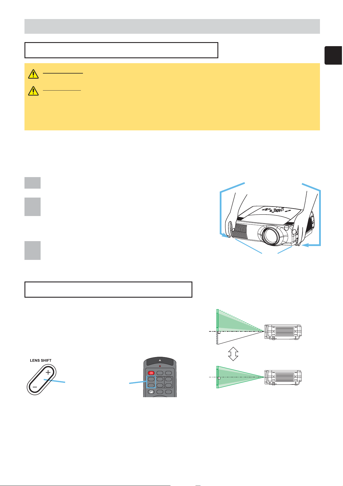
Using The Lens Shift Buttons
The lens of this projector can be shifted
vertically. When you want to finely adjust the
picture position, use the LENS SHIFT buttons
of the projector.
Elevator buttons
Elevator feet
Projector
LENS SHIFT buttons
Remote control
15
Page 16
Setting Up (continued)
Setting Up (continued)
Connecting Your Devices
WARNING • Whenever attempting to connect other devices to the projector, read
thoroughly, this manual and the manual of each device to be connected. Incorrect
connecting could result in fire or electrical shock.
CAUTION
Attempting to connect a live device to the projector may generate extremely loud
noises or other abnormalities that may result in malfunction and/or damage to the
device and/or projector.
ATTENTION
may result in malfunction and/or damage to the device and/or projector. Refer to the section
“Technical” of this manual for the pin assignment of connectors and RS-232C communication data.
•
Some cables have to be used with core set. Use the accessory cable or a designated-type cable
for the connection. For cables that have a core only at one end, connect the core to the projector.
• Secure the screws on the connectors and tighten.
• Whenever attempting to connect a laptop computer to the projector, be sure to
activate the laptop’s RGB external image output (set the laptop to CRT display or to
simultaneous LCD and CRT display). For details on how this is done, please refer to
the instruction manual of the corresponding laptop computer.
• TURN OFF ALL DEVICES prior to connecting them to the projector.
•
Make sure that you connect devices to the correct port. Incorrect connection
NOTE
these modes may not be compatible with this projector.
• For some RGB input modes, the optional Mac adapter is necessary.
• When the image resolution is changed on a computer, depending on an input,
automatic adjust function may take some time and may not be completed. In this
case, you may not be able to see a check box to select “Yes/No” for the new
resolution on Windows. Then the resolution will go back to the original. It might be
recommended to use other CRT or TFT monitors to change the resolution.
NOTE
• Plug-and-Play is a system incorporated in the computer, its operating system and
peripheral equipment (i.e. display devices).
•
This projector is compatible with VESA DDC 2B. Plug-and-Play can be achieved by
connecting this projector to computers that are VESA DDC (display data channel) compatible.
• Please take advantage of this function by connecting the accessory RGB cable to the
RGB port (DDC 2B compatible). Plug-and-Play may not work properly if any other
type of connection is attempted.
•
Please use the standard drivers in your computer as this projector is a Plug-and-Play monitor.
• The TLP-SX3500's M1-D is compatible with HDCP (High-bandwidth Digital Content
Protection) and therefore capable od displaying video from HDCP compatible DVD
players, et al. However, if the HDCP standards are modified, the TLP-SX3500's M1-D
might not be able to display video from HDCP compatible developed in conformance
to such modified HDCP standards.
• Some computers may have multiple display screen modes. Use of some of
Plug-and-Play Capability
16
Page 17
Setting Up (continued)
R/CR/PR G/Y B/CB/PB H V
VIDEOR-AUDIO IN-L
S-VIDEO
BNC
RGB
AUDIO IN1
AUDIO IN2
RGB OUT
AUDIO OUT
REMOTE CONTROL
R/C
R/PR G/Y B/CB/PB HV
Y
CONTROL NETWORK
CR/PR
CB/PB
A
E
F G
CR/PR
CB/PB
REMOTE CONTROL
VIDEOR-AUDIO IN-L
S-VIDEO
BNC
RGB
AUDIO IN1
AUDIO IN2
RGB OUT
AUDIO OUT
G/Y H V
Y
CONTROL NETWORK
R/CR/PR B/CB/PB
B
D
CR/PR
CB/PB
REMOTE CONTROL
VIDEOR-AUDIO IN-L
S-VIDEO
BNC
RGB
AUDIO IN1
AUDIO IN2
RGB OUT
AUDIO OUT
R/C
R/PR G/Y B/CB/PB HV
Y
CONTROL NETWORK
C
D
Setting Up (continued)
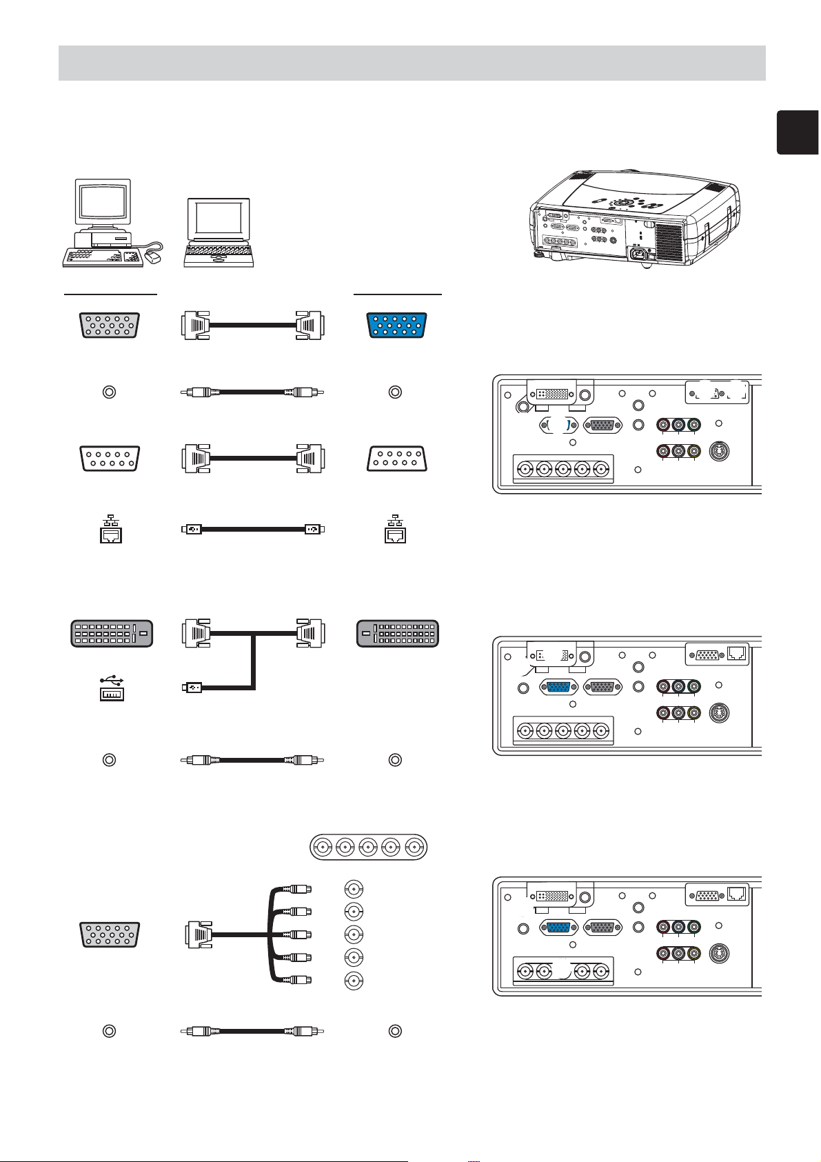
Please refer to the following (for example) for connecting your devices. See the rear of the projector.
You can see the ports.
Examples of connection with a computer
K
E
Y
S
T
O
N
E
L
E
N
M
S S
1
D
H
I
F
T
R
G
B
S
I
E
N
P
A
U
R
T
C
H
BNG
C
O
MP
O
N
E
N
T
R
E
S
ET
IN
S-
T
V
E
R
ID
E
O
V
I
D
EO
S
T
A
AU
D
I
O
I
N1
REM
O
C
TE
ONTROL
CON
A
U
D
IO
R/C
TROL
I
N2
RGB
AU
D
IO
O
RGB OUT
UT
CR/
PR
Ca
/Pa
R
/P
R
G/Y
B/C
B
/P
B
BNC
Y
H
V
R
AU
D
IO
I
N
L
V
ID
E
O
S
F
O
C
U
S
ZO
O
M
M
E
N
U
N
D
B
Y
/
O
N
T
EM
P
LAM
P
NETWORK
-V
ID
E
O
Computer Projector
A
RGB out RGB cable RGB
E
Audio out Stereo Mini cable AUDIO IN 2
F
RS-232C port RS-232C cable CONTROL
Network port CAT-5 cable NETWORK
■ If using a M1-D input (to mouse control)
DVI port M1-D
USB port M1-D cable
Audio out Stereo Mini cable AUDIO IN 1
■ If using a BNC input
R/C
R/PR
G/Y
B/PB
B/C
RGB out
BNC cable
H
V
G
B
D
C
Audio out Stereo Mini cable AUDIO IN 1
D
17
Page 18

Setting Up (continued)
CR/PR
CB/PB
VIDEOR-AUDIO IN-L
S-VIDEO
BNC
RGB
AUDIO IN1
AUDIO IN2
RGB OUT
AUDIO OUT
R/C
R/PR G/Y B/CB/PB HV
Y
CONTROL NETWORK
REMOTE CONTROL
H I
CR/PR
CB/PB
REMOTE CONTROL
VIDEOR-AUDIO IN-L
S-VIDEO
BNC
RGB
AUDIO IN1
AUDIO IN2
RGB OUT
AUDIO OUT
R/C
R/PR G/Y B/CB/PB HV
Y
CONTROL NETWORK
H J
CR/PR
CB/PB
REMOTE CONTROL
VIDEOR-AUDIO IN-L
S-VIDEO
BNC
RGB
AUDIO IN1
AUDIO IN2
RGB OUT
AUDIO OUT
R/C
R/PR G/Y B/CB/PB HV
Y
CONTROL NETWORK
H
K
R-AUDIO IN-L VIDEO
R-AUDIO IN-L VIDEO
CR/PR CB/PB Y
R-AUDIO IN-L VIDEO
CR/PR
CB/PB
REMOTE CONTROL
VIDEOR-AUDIO IN-L
S-VIDEO
BNC
RGB
AUDIO IN1
AUDIO IN2
RGB OUT
AUDIO OUT
R/C
R/PR G/Y B/CB/PB HV
Y
CONTROL NETWORK
HI
K
Setting Up (continued)
Examples of connection with a VCR/DVD Player
VCR/DVD Player Projector
Audio out (R)
Audio out (L)
Video out
R-AUDIO IN
AUDIO IN-L
VIDEO IN
■ If using a s-video signal
S-video out S-video cable S -VIDEO
Audio out (R)
Audio out (L)
R-AUDIO IN
AUDIO IN-L
■ If using a component signal
C
R/PR out
C
B/PB out
Y out
CR/PR
CB/PB
Y
H
I
J
H
K
Audio out (R)
Audio out (L)
■ If using a SCART RGB input
SCART
RGB out
SCART
adapter
18
R-AUDIO IN
AUDIO IN-L
CR/PR CB/PB Y
R-AUDIO IN-L VIDEO
R (CR/PR)
B (C
B/PB)
G (Y)
R-AUDIO IN
AUDIO IN-L
VIDEO IN
H
K
H
I
Page 19

Setting Up (continued)
CR/PR
CB/PB
REMOTE CONTROL
VIDEOR-AUDIO IN-L
S-VIDEO
BNC
RGB
AUDIO IN1
AUDIO IN2
RGB OUT
AUDIO OUT
R/C
R/PR G/Y B/CB/PB HV
Y
CONTROL NETWORK
L
CR/PR
CB/PB
REMOTE CONTROL
VIDEOR-AUDIO IN-L
S-VIDEO
BNC
RGB
AUDIO IN1
AUDIO IN2
RGB OUT
AUDIO OUT
R/C
R/PR G/Y B/CB/PB HV
Y
CONTROL NETWORK
M
Setting Up (continued)
Connecting to a monitor
Monitor Projector
L
RGB in RGB cable RGB OUT
Connecting to a speaker (with amplifier)
Speaker Projector
M
Audio in Stereo Mini cable AUDIO OUT
Connecting The Power Supply
WARNING •
connections may result in fire and/or electrical shock. Please adhere to the “Before using”
section of this manual and the following.
•
Only plug the power cord into outlets rated for use with the power cord’s specified voltage range.
•
Only use the power cord that came with the projector. If it is damaged, contact your dealer to
newly get correct one.
• Never modify the power cord.
•
Make sure that you firmly connect the power cord to the projector and wall outlet.
Connect the connector of the power cord to
1
the AC inlet of the projector.
Firmly plug the power cord’s plug into the
2
outlet.
Use extra caution when connecting the power cord as incorrect or faulty
KEYST
O
N
L
EN
AU
DIO IN1
REMOTE CONTROL
AU
DIO
I
N2
RGB
AUDIO OUT
RGB OUT
CR/PR
R/C
R
/P
R
G/Y
B/C
Ca/Pa
B
/P
B
H
V
R-A
UDIO
I
N-L
BNC
V
AC Inlet
Connector Plug
E
M
S S
1-D
HIFT
RG
B
SEARC
I
NP
U
T
H
B
N
G
COM
P
ONENT
R
E
SE
T
I
N
S-VID
T
E
R
F
E
O
VID
E
O
S
TAN
DBY/
CONTROL
NETWORK
Y
ID
EO
S-VIDE
OC
US
Z
O
O
M
M
E
N
U
O
N
TEM
P
LAMP
O
Outlet
19
Page 20

Remote Control
STANDBY/ON
VIDEO
LA
SER
INDICATOR
ESC MENU
POSITION
RESET AUTO
KEYSTONE
1 2 3
ID CHANGE
SEARCH
ON
OFF
FREEZE MUTE
MAGNFY
PinP
VOLU
ME
RGB
BLANK
PREVIOUS
NEXT
ASPECT LASER
LENS SHIFT
+
–––
++
FOCUS ZOOM
Remote Control
About The Laser Pointer
WARNING • The laser pointer of the remote control is used in place of a finger or
rod. Never look directly into the laser beam outlet or point the laser beam at other
people. The laser beam can cause vision problems.
CAUTION
than those specified herein may result in hazardous radiation exposure.
AVOID EXPOSURE-LASER
CAUTION
Comples with 21 CFR, 1040.10 AND 1040.11
IEO60825-1:1993+A1:1997+A2:2001
LASER-STRAHLING
NICHT IN DEN STRAHL BLICKEN
LASER KLASSE 2
WAVE LENGTH:640-660nm MAX OUTPUT:1mW
レーザー光
ビームをのぞきこまないこと
クラス2レーザー製品 JISC6802(1998)
最大出力:1.0mW 波長:640−660nm
MODEL:H-IRC4
INTERLINK K.K.
1-10-7 HIGASHIKANDA CHIYODA-KU,TOKYO,JAPAN
101-0031
• Use of controls or adjustments or performance of procedures other
RADIATION IS EMITTED
FROM THIS APERTURE
LASER RADIATION
DO NOT STARE INTO BEAM
WAVE LENGTH: 640-660nm
MAX OUTPUT: 1mW
CLASS 2 LASER PRODUCT
MOUSE
レーザー光をのぞき込まないこと。
MANUFACTURER: B
MANUFACTURED
JANUARY,2003
MADE IN CHINA
レーザー光を人に向けないこと。
子供に使わせないこと。
製造者:INTERLINK ELECTRONICS
P S
C
JQA
MADE IN CHINA
This remote control has a laser pointer in place of a finger or rod. The laser beam works and the
LASER INDICATOR lights while the LASER button is pressed.
Loading Batteries
CAUTION About the battery
• Keep a battery away from children and pets.
• Use only the battery specified: two AA batteries.
• Do not mix new battery with used one.
• Make sure the plus and minus terminals are correctly aligned when loading the
battery (as indicated in the remote control).
• Dispose of batteries in accord with environmental laws.
Remove the battery
1
cover.
Slide back and
remove the battery
cover in the direction
of the arrow.
Insert the batteries.
2
Align and insert the
two AA batteries
according to their plus
minus terminals (as
indicated in the remote
control).
3
Close the battery
cover.
Replace the battery
cover in the direction
of the arrow and snap
it back into place.
20
Page 21

Remote Control (continued)
I
N
T
E
R
I
N
P
U
T
M
1
-
D
R
G
B
B
N
G
S
-
V
ID
E
O
S
T
A
ND
B
Y
/
O
N
T
E
M
P
V
ID
E
O
C
O
M
P
O
N
E
N
T
L
A
M
P
K
E
Y
S
T
O
N
E
S
E
A
R
C
H
RE
S
E
T
M
E
N
U
F
O
C
U
S
L
E
N
S
S
H
I
F
T
Z
O
O
M
I
NT
E
R
I
N
P
U
T
M
1
-D
R
G
B
B
N
G
S
V
I
D
E
O
S
TA
N
D
B
Y
/
O
N
T
E
M
P
V
I
D
E
O
C
O
M
P
O
N
E
N
T
L
A
M
P
K
E
Y
S
T
O
N
E
S
E
A
R
C
H
R
E
S
E
T
M
E
N
U
F
O
C
U
S
L
E
N
S
S
H
I
F
T
Z
O
O
M
VI
D
EO
R
A
U
D
I
O
I
N
-L
S-
VI
D
EO
BN
C
R
G
B
A
U
D
I
O
I
N
1
A
U
D
I
O
I
N
2
R
G
B O
U
T
A
U
D
I
O
O
U
T
R
E
MO
T
E
C
O
N
T
R
O
L
R
/
C
R
/
P
R
G
/
Y
B/
C
B
/
P
B
H
V
Y
C
O
N
T
R
O
L
N
ET
W
O
R
K
C
R
/
PR
C
a
/
P
a
approximately
3 meters
30 degrees
30 degre
es
approximately
3 meters
20 degrees
20 degrees
Remote Control (continued)
Operating The Remote Control
CAUTION • Do not disassemble the remote control.
• Do not place the remote control near the projector’s lens, fan, or vents.
• Do not drop or otherwise expose the remote control to physical impact.
•
Do not get the remote control wet or place it on wet objects on it. Doing so may result in malfunction.
• Remove the batteries from the remote control and store them in a safe place if you
won't be using the remote control for an extended period.
NOTE
•
When strong light, such as direct sunlight or light from an extremely close range (such as from an
• Replace the batteries whenever the remote control starts to malfunction.
inverter fluorescent lamp), hits the projector's remote sensor, the remote control may cease to function.
Adjust the direction of the projector to keep light from directly hitting the projector's remote sensor.
The remote control works with the projector’s
remote sensor.
•
Front remote sensor is 3 meters with a 60
degree range (30 degrees to the left and
right of a remote sensor).
Rear remote sensor is 3 meters with a 40
degree range (20 degrees to the left and
right of a remote sensor).
•
Also a remote signal reflected in the screen etc.
may be available. If it is difficult to send a remote signal to the sensor directly, please try.
•
Since the remote control uses infrared light to send signals to the projector (Class1 LED), be sure to use the
remote control in an area free from obstacles that could block the remote control’s output signal to the projector.
memo
You can use the remote control as a wired remote control, by connecting the REMOTE CONTROL
ports of the main unit and remote control via an audio cable (3.5 dia. stereo mini cable with plugs).
Using The Remote ID Feature
This is the function to properly use when you use two or
three same type projectors at the same time. This function
should be used combining a setup of a projector.
Set the ID number to the projector beforehand,
1
referring to the item “IR REMOTE ID” of the section
“OPTION Menu”.
memo
REMOTE ID” of the OPTION menu, the projector is
controlled by a remote control irrespective of the
position of the ID CHANGE switch.
Slide the knob of the switch into the position of the
2
ID number of the projector you want to control.
When the ALL is selected to the item “IR
LASER INDICATOR
STANDBY/ON
VIDEO
+
++
LENS SHIFT
FOCUS ZOOM
–––
ASPECT
BLANK
PREVIOUS
MOUSE
ESC MENU
POSITION
RESET AUTO
MAGNFY
PinP
ON
FREEZE MUTE
OFF
KEYSTONE
1 2 3
ID CHANGE
RGB
LASER
NEXT
ID CHANGE
switch
VOLUME
SEARCH
21
Page 22

Remote Control (continued)
Remote Control (continued)
Using The Mouse/Keyboard Control Function
CAUTION • Before connecting, read the manuals of the device you will connect.
Mistaken use of the mouse/keyboard control could damage your equipment.
• Only connect to a PC or an USB Hub connected PC.
• Do not unplug the connector cables while the computer is operating.
Using the USB control feature, you can use the remote control as a simplified mouse or
keyboard of the computer.
Connect the M1-D port of the projector to the computer via the M1-D cable. Then
functions illustrated below will be enabled.
memo
Windows 95 OSR 2.1 or higher. It may not be
possible to use the remote control, depending
The USB control can be used with
STANDBY/ON
LENS SHIFT
on the computer’s configurations and mouse
drivers.
memo
The function can be used only for the
functions illustrated on the right.
memo
The projector would be enumerated as a
POSITION
mouse and a keyboard of HID (Human
Interface Device) class devices, after
connecting cable.
LASER INDICATOR
VIDEO
RGB
+
++
FOCUS ZOOM
–––
ASPECT
BLANK
LASER
PREVIOUS
NEXT
MOUSE
ESC MENU
RESET AUTO
MAGNFY
PinP
VOLUME
ON
FREEZE MUTE
OFF
KEYSTONE
SEARCH
1 2 3
ID CHANGE
(Front)
Mouse left button
Mouse move pointer
Keyboard
Arrow keys / / /
Mouse right button
Keyboard ESC key
(Rear)
22
Page 23

STANDBY/ON
VIDEO
LASER INDICATOR
RGB
LENS SHIFT
+
–––
++
FOCUS ZOOM
I
N
T
E
R
I
N
P
U
T
M
1-D
R
GB
B
N
G
S-V
I
D
EO
S
T
A
N
D
BY
/
O
N
T
E
M
P
V
ID
E
O
C
O
M
P
O
N
E
N
T
L
A
M
P
K
E
Y
ST
O
NE
S
E
A
R
C
H
R
E
S
E
T
M
E
N
U
F
O
CUS
LE
N
S
S
H
I
F
T
Z
O
OM
V
I
D
E
O
R
A
UD
IO
I
N
L
S-
V
I
D
E
O
BNC
R
G
B
A
U
D
I
O
I
N
1
A
U
D
I
O
I
N
2
R
GB
O
U
T
A
U
D
I
O
O
U
T
REM
OT
E
CON
TROL
R/C
R
/
P
R
G/Y
B
/
C
B
/
P
B
H
V
Y
C
ON
T
ROL
NETWOR
K
CR/
PR
C
a/
Pa
I
N
T
E
R
I
N
P
UT
M
1
-D
R
GB
B
N
G
S
V
I
D
E
O
ST
A
N
D
B
Y
/
O
N
T
E
M
P
V
I
D
E
O
C
O
M
P
O
N
E
N
T
L
A
M
P
K
E
YST
O
N
E
S
E
A
R
C
H
R
ESE
T
M
E
N
U
F
O
C
U
S
L
E
N
S
S
H
I
F
T
Z
O
OM
V
I
D
E
O
R
A
U
D
I
O
I
N
L
S-V
ID
E
O
BNC
RG
B
A
U
D
I
O
I
N
1
A
UD
IO I
N2
R
GB
OUT
A
U
D
IO O
U
T
REMOTE
CON
T
R
OL
R
/C
R
/
P
R
G/Y
B/
C
B
/
P
B
H
V
Y
CO
N
TROL
N
ET
WOR
K
CR
/
PR
Ca/
Pa
STANDBY/ON
VIDEO
LASER INDICATOR
RGB
LENS SHIFT
+
–––
++
FOCUS ZOOM
I
N
T
E
R
I
N
P
U
T
M
1
-
D
R
G
B
BNG
S
V
I
D
E
O
S
T
A
ND
B
Y
/
O
N
T
E
M
P
V
I
D
E
O
C
O
M
P
O
N
E
N
T
L
A
M
P
K
E
Y
S
T
ON
E
S
E
A
R
C
H
R
E
S
ET
M
E
N
U
F
O
C
U
S
LE
NS
S
H
IF
T
Z
O
O
M
V
I
D
E
O
R
A
U
D
I
O
I
N
L
S
V
I
D
E
O
BNC
RG
B
A
U
D
I
O
I
N
1
A
U
D
I
O
I
N
2
R
GB
O
U
T
A
U
D
I
O
O
U
T
R
E
M
O
T
E
C
O
N
T
RO
L
R
/C
R
/
P
R
G/
Y
B
/
C
B
/
P
B
H
V
Y
C
O
N
TR
OL
N
ET
W
O
RK
C
R
/
P
R
C
a
/Pa
Power ON/OFF
STANDBY/ON
VIDEO
LASER INDICATOR
RGB
BLANK ASPECT LASER
LENS SHIFT
+
–––
++
FOCUS ZOOM
Power ON/OFF
WARNING • When the power is ON, a strong light is emitted. Do not look
into the lens or vents of the projector.
NOTE
• Turn the power on/off in right order. Please power on the projector before
the connected devices. Power off the projector after the connected devices.
Turning On The Power
1
2
3
4
5
STANDBY/ON
Remove the lens cap.
Set the power switch to [ | ] (ON).
The STANDBY/ON indicator will light to solid orange.
Press the STANDBY/ON button.
The projector lamp will light up and the
STANDBY/ON indicator will begin blinking green.
Power switch (ON position)
When the power is completely on, the indicator
will stop blinking and light green.
Use the LENS SHIFT buttons to shift the
picture upward or downward.
Select an input signal according to the
section “Selecting An Input Signal” of the
following page.
STANDBY/ON button / indicator
STANDBY/ON
LENS SHIFT
buttons
STANDBY/ON
button
Turning Off The Power
Press the STANDBY/ON button.
1
2
4
The message “Power off?” will appear on
the screen for approximately 5 seconds.
Press the STANDBY/ON button again while
“Power off?” the message is visible.
The projector lamp will go off, and the
STANDBY/ON indicator will begin blanking orange.
Then the STANDBY/ON indicator will stop blinking
and light to solid orange when the lamp cooling is
complete.
Switch the power switch to [O] (OFF).
3
The STANDBY/ON indicator will go off.
Attached the lens cap.
STANDBY/ON
STANDBY/ON button / indicator
STANDBY/ON
STANDBY/ON
button
Power switch (OFF position)
23
Page 24

Operating
T
T
C
Operating
Selecting An Input Signal
Select an input signal.
1
■ Using the INPUT dial
Turn the INPUT dial of the projector.
Turning the dial cycles through the input ports as
shown below. Select the signal you wish to project.
M1-D RGB BNC
SEARCH button
VIDEO
S-VIDEO COMPONEN
■ Using SEARCH button
Press the SEARCH button of the projector or the
remote control.
Pressing the button automatically cycles through input
ports and displays the picture of retrieved signal.
memo
If no signal is found or the projector is unstable to
find an input signal at any of its ports, it will turn to the state
it was in prior to the search.
STANDBY/ON
M1-D RGB BNC
LENS SHIFT
BLANK
VIDEO
S-VIDEO COMPONEN
PREVIOUS
■ Using RGB button
Press the RGB button of the remote control.
Pressing the button toggles between the RGB ports
as shown below Select the signal you wish to project.
M1-D RGB BN
POSITION
MAGNFY
INPUT dial
A
U
D
I
O
I
N
1
A
U
D
I
O
I
N2
R/
C
R
/
P
LASER INDICATOR
VIDEO
RGB
+
++
FOCUS ZOOM
–––
ASPECT
LASER
NEXT
MOUSE
ESC MENU
RESET AUTO
PinP
VOLUME
ON
FREEZE MUTE
OFF
KEYSTONE
SEARCH
1 2 3
ID CHANGE
K
E
Y
S
T
O
N
E
L
E
N
M
S
1
S
-
D
H
IFT
R
G
B
S
I
E
NP
A
U
R
T
C
H
B
N
G
C
O
M
P
O
N
E
N
T
R
E
S
E
T
I
N
S
T
-V
E
R
I
D
F
O
E
O
C
U
S
Z
O
O
M
V
I
D
M
EO
E
N
U
S
T
A
N
D
B
Y
/
O
N
T
E
M
P
LA
M
P
R
E
M
OT
C
O
E
N
C
TR
O
OL
N
T
R
O
L
N
ET
W
OR
K
R
G
B
A
U
D
I
O
O
RGB OU
U
T
T
CR/P
R
C
a
/
P
a
Y
R
G/Y
B
/
C
B
/
P
B
H
V
R
A
U
D
IO
I
N
L
V
I
D
E
O
S-
V
I
D
E
O
BNC
VIDEO button
RGB button
SEARCH button
24
■ Using VIDEO button
Press the VIDEO button of the remote control.
Pressing the button toggles between the VIDEO ports
as shown below Select the signal you wish to project.
S-VIDEO VIDEOCOMPONENT
Use the ZOOM buttons to adjust the screen size.
2
Use the FOCUS buttons to adjust the focus.
3
FOCUS
buttons
A
U
D
IO
I
N
1
REMOTE
A
U
D
I
O
I
N
2
RG
B
RGB OUT
R/C
R
/
P
R
G/Y
B
/
C
B
/P
B
H
V
BNC
ZOOM
buttons
K
E
YS
T
O
NE
L
E
N
M1-D
S
S
H
I
F
T
R
G
B
S
I
E
N
P
A
UT
R
C
H
B
N
G
C
O
M
P
O
N
E
N
T
R
E
S
ET
I
N
S-
T
V
E
R
I
D
F
O
E
O
C
U
S
Z
O
OM
V
ID
M
E
O
E
N
U
S
T
A
N
D
B
Y/
O
N
T
E
M
P
L
A
M
P
C
ON
C
TROL
ONT
ROL
N
ET
W
O
RK
A
U
D
I
O
O
UT
CR/PR
Ca/P
a
Y
R
-A
U
D
I
O
IN
L
V
ID
E
O
S-
V
ID
E
O
Page 25

Operating (continued)
4:3
16:9
NORMAL REAL
4:3
16:9
SMALL
REAL
Operating (continued)
Selecting The Aspect Ratio
Press the Aspect button to toggle between the modes for
1
aspect ratio.
■ For an RGB signal
memo
NORMAL keeps the original aspect ratio of the input signal.
■ For a video signal / no signal
memo
For a HDTV signal of 1125i(1080i) or 750p(720p), only 16:9 and REAL can be
selected. REAL cannot be selected when there is no input signal.
Using The Automatic Adjustment Feature
LASER INDICATOR
STANDBY/ON
VIDEO
+
++
LENS SHIFT
FOCUS ZOOM
–––
ASPECT
BLANK
PREVIOUS
MOUSE
ESC MENU
POSITION
RESET AUTO
MAGNFY
PinP
ON
FREEZE MUTE
OFF
KEYSTONE
SEARCH
1 2 3
ID CHANGE
RGB
LASER
NEXT
VOLUME
ASPECT
button
memo The automatic adjustment operation requires approximately 10 seconds. Also,
please note that it may not function correctly with some input.
Press the AUTO button.
1
■ For an RGB signal
The Vertical position, the horizontal position, the clock
phase and horizontal size will be automatically adjusted.
LASER INDICATOR
STANDBY/ON
VIDEO
+
++
LENS SHIFT
FOCUS ZOOM
–––
ASPECT
BLANK
RGB
LASER
And the aspect ratio will be automatically selected.
memo
size prior to attempting to use this feature. Dark pictures may still
be incorrectly adjusted. Use a bright screen when adjusting.
■ For a video signal or s-video signal
The signal type mode best suited for the respective input
signal will be selected automatically.
This function is available only when the AUTO is selected to the
Make sure that the application window is set to its maximum
PREVIOUS
ESC MENU
POSITION
MAGNFY
ON
OFF
MOUSE
RESET AUTO
FREEZE MUTE
KEYSTONE
ID CHANGE
1 2 3
NEXT
AUTO
button
PinP
VOLUME
SEARCH
item VIDEO of the INPUT menu. For a component video signal, the
signal type is identified automatically independently of this function.
■ For a video signal, s-video signal or component video signal
The vertical position and horizontal position will be automatically adjusted.
■ For a component video signal
The aspect ratio will be automatically selected.
The clock phase will be automatically adjusted.
25
Page 26

Operating (continued)
Operating (continued)
Adjusting The Picture Position
memo This function is not available for M1-D signals.
Press the POSITION button.
1
As illustrated on the right, a
dialog will appear on the
screen to aid you in adjusting
POSITION
the position.
Use the cursor buttons / / / to adjust the
2
position.
memo
When you want to initialize the position, press
the RESET button during adjustment.
Press the POSITION button again to close the
3
dialog and complete this operation.
memo
Even if you don't do anything, the dialog will
automatically disappear after a few seconds.
Correcting The Keystone Distortion
LASER INDICATOR
STANDBY/ON
VIDEO
+
++
LENS SHIFT
FOCUS ZOOM
–––
ASPECT
BLANK
PREVIOUS
MOUSE
ESC MENU
POSITION
RESET AUTO
MAGNFY
PinP
ON
FREEZE MUTE
OFF
KEYSTONE
SEARCH
1 2 3
ID CHANGE
RGB
LASER
NEXT
VOLUME
Cursor
buttons
POSITION
button
RESET
button
Press the KEYSTONE button.
1
As illustrated on the right, a dialog
will appear on the screen to aid you
in correcting the keystone
distortion.
Use the cursor buttons / to
2
select the direction of distortion to
correct ( or ).
Use the cursor buttons / to correct the
3
distortion.
Press the KEYSTONE button again to close the
4
dialog and complete this operation.
memo
Even if you don't do anything, the dialog will
automatically disappear after a few seconds.
memo When this adjustment is excessive, certain
degradation may appear on the picture. Also,
please note that it may not function correctly with
some input.
KEYSTONE
+
0
LASER INDICATOR
STANDBY/ON
VIDEO
RGB
+
++
LENS SHIFT
FOCUS ZOOM
–––
LASER
ASPECT
BLANK
Cursor
PREVIOUS
NEXT
MOUSE
+
0
ESC MENU
POSITION
MAGNFY
ON
OFF
ID CHANGE
RESET AUTO
PinP
VOLUME
FREEZE MUTE
KEYSTONE
SEARCH
1 2 3
buttons
KEYSTONE
button
26
Page 27

Operating (continued)
Operating (continued)
Adjusting The Volume
Press the VOLUME button.
1
As illustrated on the right, a dialog
will appear on the screen to aid you
in adjusting the volume.
Use the cursor buttons / to
2
adjust the volume.
Press the VOLUME button again to close the
3
dialog and complete this operation.
memo
Even if you don't do anything, the dialog will
automatically disappear after a few seconds.
Muting The Sound
Press the MUTE button.
1
As illustrated on the right, a dialog
will appear on the screen indicating
that you have muted the sound.
VOLUME
16
VOLUME
LASER INDICATOR
STANDBY/ON
VIDEO
+
++
LENS SHIFT
FOCUS ZOOM
–––
ASPECT
BLANK
POSITION
STANDBY/ON
LENS SHIFT
BLANK
LASER
PREVIOUS
NEXT
MOUSE
ESC MENU
RESET AUTO
MAGNFY
PinP
VOLUME
ON
FREEZE MUTE
OFF
KEYSTONE
SEARCH
1 2 3
ID CHANGE
LASER INDICATOR
VIDEO
+
++
FOCUS ZOOM
–––
ASPECT
LASER
PREVIOUS
NEXT
MOUSE
RGB
Cursor
buttons
VOLUME
button
RGB
Press the MUTE or VOLUME
2
button to restore the sound.
memo
Even if you don't do anything,
16
the dialog will automatically
disappear after a few seconds.
Temporarily Blanking The Screen
Press the BLANK button.
1
The input signal screen will shut off, and a BLANK
screen will appear.
memo You can set the BLANK screen using the
menu. Please refer to the item “BLANK” of the
table of the section “SCREEN Menu”.
Press the BLANK button again to remove the
2
blank screen, and return to the input signal screen.
ESC MENU
POSITION
RESET AUTO
MAGNFY
PinP
ON
FREEZE MUTE
OFF
KEYSTONE
1 2 3
ID CHANGE
LASER INDICATOR
STANDBY/ON
VIDEO
+
++
LENS SHIFT
FOCUS ZOOM
–––
ASPECT
BLANK
PREVIOUS
MOUSE
ESC MENU
POSITION
RESET AUTO
MAGNFY
PinP
ON
FREEZE MUTE
OFF
KEYSTONE
1 2 3
ID CHANGE
SEARCH
RGB
LASER
NEXT
VOLUME
SEARCH
VOLUME
MUTE
button
BLANK
button
27
Page 28

Operating (continued)
Operating (continued)
Freezing The Screen
Press the FREEZE button.
1
As illustrated on the right, a
dialog will appear on the
screen, and the screen will
FREEZE
LASER INDICATOR
STANDBY/ON
VIDEO
+
++
LENS SHIFT
FOCUS ZOOM
–––
ASPECT
BLANK
RGB
LASER
freeze at the current image.
PREVIOUS
NEXT
ESC MENU
POSITION
MAGNFY
ON
OFF
ID CHANGE
MOUSE
RESET AUTO
PinP
VOLUME
FREEZE MUTE
KEYSTONE
SEARCH
1 2 3
FREEZE
button
Press the FREEZE button again to restore the
2
screen to normal.
The icon “||” will change to the icon “ ”. And after
a couple of seconds, the dialog will be closed and
the screen will be restored to normal.
memo
The freezing feature will automatically finish if a remote control’s
button that changes some display state (ex. blanking the screen,
displaying a dialog or a menu, adjusting the picture, changing the input
signal) is pressed, or a button of projector is pressed.
NOTE
•
If the projector continues projecting the same image for a long time (i.e. you forget to exit FREEZE mode),
the image might possibly remain as an afterimage. Do not leave the projector in FREEZE mode for too long.
Using The Magnify Feature
Press the MAGNIFY
1
button.
As illustrated on the right, a dialog
will appear on the screen to aid
you in magnifying the picture.
Press the POSITION button, then use the cursor
2
buttons / / / to select the area to zoom.
Press the POSITION button again to finalize the
3
zoom area.
Use the cursor buttons / to adjust the zoom
4
level.
Press the MAGNIFY button again to close the
5
dialog and complete this operation.
ON
OFF
MAGNIFY
LASER INDICATOR
STANDBY/ON
VIDEO
+
++
LENS SHIFT
FOCUS ZOOM
–––
ASPECT
BLANK
PREVIOUS
MOUSE
ESC MENU
POSITION
RESET AUTO
MAGNFY
PinP
ON
FREEZE MUTE
OFF
KEYSTONE
SEARCH
1 2 3
ID CHANGE
RGB
LASER
NEXT
VOLUME
Cursor
buttons
POSITION
button
MAGNIFY
buttons
28
memo
The magnify feature will automatically finish if the
automatic adjustment is execute, or the aspect, the signal
type mode of video or the signal input state is changed.
Page 29

Operating (continued)
Operating (continued)
Displaying The Child Window
memo
This feature called "PinP (Picture in Picture)" is available only when a RGB signal is selected
to main screen. And this feature does not work when UXGA (1600 x 1200) or higher signal is input.
Press the PinP button.
1
The child window with a picture of a video signal
will appear.
Press the PinP button again to change the size of
2
the child window or close the window.
Small child window Large child window
No child window
memo
You can select the video signal to display in the
child window, and the position of the child window.
Please refer to the items “P.INP. INPUT” and “P.INP.
POSIT.” of the table of the section “INPUT Menu”.
LASER INDICATOR
STANDBY/ON
VIDEO
+
++
LENS SHIFT
FOCUS ZOOM
–––
ASPECT
PREVIOUS
ESC MENU
MAGNFY
ON
OFF
KEYSTONE
ID CHANGE
LASER
NEXT
MOUSE
RESET AUTO
PinP
VOLUME
FREEZE MUTE
SEARCH
1 2 3
BLANK
POSITION
RGB
PinP button
Selecting An Audio Input
memo
When the child window is on the
1
screen, press the VOLUME button.
As illustrated on the right, a dialog
will appear on the screen.
Use the cursor buttons / to
2
select an audio input.
RGB (Audio input for the main screen)
Video (Audio input for the child window)
memo
buttons
The Volume”.
This feature is available only when the child window is on the screen.
You also can adjust the volume using the cursor
/
. Please refer to the section “Adjusting
VOLUME
RGB Video
16
LASER INDICATOR
STANDBY/ON
VIDEO
+
++
LENS SHIFT
FOCUS ZOOM
–––
ASPECT
BLANK
POSITION
PREVIOUS
ESC MENU
MAGNFY
ON
OFF
KEYSTONE
ID CHANGE
LASER
NEXT
MOUSE
RESET AUTO
PinP
VOLUME
FREEZE MUTE
SEARCH
1 2 3
RGB
Cursor
buttons
VOLUME
button
Press the VOLUME button again to close the
3
dialog and complete this operation.
memo
Even if you don’t do anything, the dialog will
automatically disappear after a few seconds.
29
Page 30

Multifunctional Settings
: SELECT
MENU
MAIN
PICTURE-1
PICTURE-2
INPUT
AUTO
SCREEN
OPTION
NETWORK
VOLUME
SPEAKER
IR REMOTE
IR REMOTE ID
LAMP TIME
FILTER TIME
SERVICE
RESET
16
TURN ON
ALL
1234 h
4321 h
: SELECT
MENU
MAIN
PICTURE-1
PICTURE-2
INPUT
AUTO
SCREEN
OPTION
NETWORK
VOLUME
SPEAKER
IR REMOTE
IR REMOTE ID
LAMP TIME
FILTER TIME
SERVICE
RESET
16
TURN ON
ALL
1234 h
4321 h
Multifunctional Settings
Using The Menu Functions
This projector has the following menus: MAIN, PICTURE-1, PICTURE-2, INPUT, AUTO,
SCREEN, OPTION and NETWORK. Each of these menus is operated using the same
methods. The basic operations of these menus are as follows.
Press the MENU button.
1
The menu will appear on
the screen.
Use the cursor buttons
2
/ to select a menu,
then press the (or the
ENTER) button to
progress.
The display of the
selected menu will
appear.
Use the cursor buttons
3
/ to select an item,
then press the (or the
ENTER) button to
progress.
The operation display of
the selected item will
appear.
LASER INDICATOR
STANDBY/ON
VIDEO
+
++
LENS SHIFT
FOCUS ZOOM
–––
ASPECT
BLANK
PREVIOUS
NEXT
MOUSE
ESC MENU
POSITION
RESET AUTO
MAGNFY
PinP
VOLUME
ON
FREEZE MUTE
OFF
KEYSTONE
SEARCH
1 2 3
ID CHANGE
RGB
LASER
Cursor
buttons
MENU
button
RESET
button
ESC button
ENTER
button
ex. Turning off the built-in speaker
1) Press the MENU button.
MENU
MAIN
BRIGHT
PICTURE-1
CONTRAST
PICTURE-2
ASPECT
INPUT
WHISPER
AUTO
MIRROR
SCREEN
LANGUAGE
OPTION
[Language]
NETWORK
RESET
: SELECT
2) Select the “OPTION”
using the button, then
press the button.
3) Select the “SPEAKER”
using the button, then
press the button.
MENU
MAIN
VOLUME
PICTURE-1
SPEAKER
PICTURE-2
IR REMOTE
INPUT
IR REMOTE ID
AUTO
LAMP TIME
SCREEN
FILTER TIME
OPTION
SERVICE
NETWORK
RESET
: SELECT
16
TURN ON
ALL
1234 h
4321 h
+0
+0
4:3
NORMAL
NORMAL
ENGLISH
OPTION
SPEAKER
TURN ON
TURN OFF
30
Use the cursor buttons / to operate the item.
4
memo
press the RESET button during the operation. Note
that the items whose functions are performed
simultaneously with operating (ex. LANGUAGE,
WHISPER, H PHASE etc.) are not reset.
memo
display, press the or ESC button.
Press the MENU button again to close the menu
5
display and complete this operation.
memo
automatically disappear after a few seconds.
When you want to reset the adjustment,
When you want to return to the previous
Even if you don’t do anything, the menu will
4) Use the cursor button
to select the “TURN OFF”.
OPTION
SPEAKER
TURN ON
TURN OFF
5) Press the MENU button.
Page 31

Multifunctional Settings (continued)
: SELECT
MENU
MAIN
PICTURE-1
PICTURE-2
INPUT
AUTO
SCREEN
OPTION
NETWORK
BRIGHT
CONTRAST
ASPECT
WHISPER
MIRROR
LANGUAGE
[Language]
RESET
+0
+0
4:3
NORMAL
NORMAL
ENGLISH
ENGLISH ó FRANÇAIS ó DEUTSCH ó ESPAÑOL ó ITALIANOó NORSK
NEDERLANDS ó PORTUGUÊS ó 日本語 ó ó
ó SVENSKA ó ó SUOMI ó POLSKI ó TÜRKÇE
Multifunctional Settings (continued)
MAIN Menu
With the MAIN menu, the items shown in the table below can be
performed. Perform each operation in accordance with the
instructions in the table below.
Item Description
BRIGHT
CONTRAST
ASPECT
WHISPER
MIRROR
Adjust the brightness using the / buttons. : Light Dark
Adjust the contrast using the / buttons. : Strong Weak
Select an aspect ratio using the / buttons. :
■ For an RGB signal
NORMAL 4:3 16:9 REAL
The NORMAL keeps the original aspect ratio of the input signal.
■ For a video signal / no signal
4:3 16:9 SMALL REAL
memo For a HDTV signal of 1125i(1080i) or 750p(720p), only the 16:9 and
REAL can be selected. REAL cannot be selected when there is no input signal.
Select the NORMAL or the WHISPER using the / buttons. :
NORMAL WHISPER
When the WHISPER is selected, acoustic noise and screen brightness are
reduced.
Select a mirror status using the / buttons. :
NORMAL H:INVERT V:INVERT H&V:INVERT
TOSHIBA
TOSHIBA
TOSHIBA
TOSHIBA
ex.
Select a menu language using the / buttons. :
LANGUAGE
Select the EXECUTE using the button to reset the MAIN menu items. :
RESET
EXECUTE CANCEL
The items of the MAIN menu are collectively returned to the initial setting. Note
that the items “WHISPER” and “LANGUAGE” are not reset.
31
Page 32

: SELECT
MENU
MAIN
PICTURE-1
PICTURE-2
INPUT
AUTO
SCREEN
OPTION
NETWORK
GAMMA
COLOR BAL R
COLOR BAL G
COLOR BAL B
SHARPNESS
COLOR
TINT
MY MEMORY
NORMAL
+0
+0
+0
+0
+0
+0
LOAD1
Multifunctional Settings (continued)
Multifunctional Settings (continued)
PICTURE-1 Menu
With the PICTURE-1 menu, the items shown in the table below can
be performed. Perform each operation in accordance with the
instructions in the table below.
Item Description
Select a gamma mode using the / buttons. :
NORMAL CINEMA DYNAMIC CUSTOM
Selecting the CUSTOM and then pressing the (or the ENTER) button calls
the CUSTOM menu.
CUSTOM Menu
Select an item using the / buttons, and press the
(or the ENTER) button to perform each function.
GAMMA COLOR TEMP R G B
memo The R, G and B can be selected only when the
USER is selected under the COLOR TEMP.
GAMMA
NORMAL
CINEMA
DYNAMIC
CUSTOM
: SELECT
GAMMA
COLOR TEMP
R
G
B
2.2
HIGH
100
100
100
GAMMA
COLOR BAL R
COLOR BAL G
COLOR BAL B
GAMMA
COLOR TEMP
R
G
B
Adjust the gamma data using the / buttons. :
Up Down
Select a color temperature using the / buttons. :
HIGH MIDDLE LOW USER
Adjust the red color level for the USER mode of the COLOR
TEMP using the / buttons. : Strong Weak
Adjust the green color level for the USER mode of the COLOR
TEMP using the / buttons. : Strong Weak
Adjust the blue color level for the USER mode of the COLOR
TEMP using the / buttons. : Strong Weak
Adjust the red color balance using the / buttons. :
Strong Weak
Adjust the green color balance using the / buttons. :
Strong Weak
Adjust the blue color balance using the / buttons. :
Strong Weak
32
SHARPNESS
COLOR
TINT
Adjust the sharpness using the / buttons. :
Clear Soft
Adjust the whole color using the / buttons. :
Strong Weak
memo This item can be selected only at a video signal.
Adjust the tint using the / buttons. :
Green Red
memo This item can be selected only at a video signal.
(This table is continued to the following page.)
Page 33

Multifunctional Settings (continued)
Multifunctional Settings (continued)
PICTURE-1 Menu (continued)
Item Description
Select a command to load or save using the / buttons, and then press
the (or the ENTER) button to perform the function.:
LOAD1 LOAD2 LOAD3 LOAD4
SAVE1 SAVE2 SAVE3 SAVE4
MY MEMORY
RESET
This projector has 4 numbered memories for adjustment data.
Performing the SAVE1, SAVE2, SAVE3 or SAVE4 puts the current adjustment
data on the memory whose number corresponds with the command’s number.
The current adjustment data of the items BRIGHT and CONTRAST in the MAIN
menu and the items in the PICTURE-1 menu is stored.
Performing the LOAD1, LOAD2, LOAD3 or LOAD4 loads the data on the
memory whose number corresponds with the command’s number, and adjusts
the picture automatically depending on the data.
Select the EXECUTE using the button to reset the PICTURE-1 menu items. :
EXECUTE CANCEL
The items of the PICTURE-1 menu are collectively returned to the initial setting.
Note that the items “MY MEMORY” and “GAMMA” of the CUSTOM menu under
the item “GAMMA” are not reset.
33
Page 34

Multifunctional Settings (continued)
Multifunctional Settings (continued)
PICTURE-2 Menu
With the PICTURE-2 menu, the items shown in the table below can
be performed. Perform each operation in accordance with the
instructions in the table below.
memo This menu cannot be selected at a M1-D signal.
Item Description
Adjust the vertical position using the / buttons. :
V POSITION
H POSITION
H PHASE
Up Down
memo This item cannot be selected for a M1-D signal.
Adjust the horizontal position using the / buttons. :
Left Right
memo This item cannot be selected for a M1-D signal.
Adjust the horizontal phase to eliminate flicker using the / buttons. :
Right Left
memo This item can be selected only at a RGB signal or a component video
signal other than a COMPONENT port input of 525i(480i)/625i(576i)/SCART
RGB.
MENU
MAIN
PICTURE-1
PICTURE-2
INPUT
AUTO
SCREEN
OPTION
NETWORK
: SELECT
V POSITION
H POSITION
H PHASE
H SIZE
OVER SCAN
RESET
20
142
31
1344
5
H SIZE
OVER SCAN
RESET
Adjust the horizontal size using the / buttons. :
Large Small
memo This item can be selected only at a RGB signal.
memo When this adjustment is excessive, the picture may not be displayed
correctly. In such a case, please reset the adjustment pressing the RESET
button during this operation.
Adjust the over-scan ratio using the / buttons. :
Small Large
memo This item can be selected only at a video signal.
memo When this adjustment is too large, certain degradation may appear at
the frame area of the picture. In such a case, please adjust small.
Select the EXECUTE using the button to reset the PICTURE-2 menu items. :
EXECUTE CANCEL
The items of the PICTURE-2 menu are collectively returned to the initial setting.
Note that the item “H PHASE” is not reset.
34
Page 35

Multifunctional Settings (continued)
Multifunctional Settings (continued)
INPUT Menu
With the INPUT menu, the items shown in the table below can be
performed. Perform each operation in accordance with the
instructions in the table below.
Item Description
Select a color space mode using the / buttons. :
AUTO RGB SMPTE240 REC709 REC601
Selecting the AUTO automatically selects the optimum mode.
COLOR SPACE
COMPONENT
memo This item can be selected only at a RGB signal or a component video
signal other than a COMPONENT port input of 525i(480i)/625i(576i)/SCART
RGB.
memo The AUTO operation may not work well at some signals. In such a case,
select a suitable mode except the AUTO.
Select a function of COMPONENT port using the / buttons. :
COMPONENT SCART RGB
When the SCART RGB is selected, the COMPONENT port function as a port for
a SCART RGB signal input. Please refer to the section “Connecting Your
Devices”.
MENU
MAIN
PICTURE-1
PICTURE-2
INPUT
AUTO
SCREEN
OPTION
NETWORK
: SELECT
COLOR SPACE
COMPONENT
VIDEO
3D-YCS
VIDEO NR
P. INP. INPUT
P. INP. POSIT.
POWERUP INPUT
AUTO
COMPONENT
AUTO
TURN OFF
LOW
VIDEO
RGB
VIDEO
3D-YCS
VIDEO NR
Select a signal type mode using the / buttons. :
AUTO NTSC PAL SECAM NTSC4.43 M-PAL N-PAL
Selecting the AUTO automatically selects the optimum mode.
memo This item is performs only at a video signal from the VIDEO port or the S-
VIDEO port. For a component video signal, the signal type is identified
automatically independently of this function.
memo The AUTO operation may not work well at some signals. If the picture
becomes unstable (ex. a irregular picture, a color lack), please select the mode
depending on the input signal.
Select the TURN ON or the TURN OFF using the / buttons. :
TURN ON TURN OFF
When the TURN ON is selected, the 3D-YCS mode works for a completely still
image, or images with few motions.
memo This item performs only at a video signal of NTSC3.58.
memo When this function performs, the setting of the item “VIDEO NR” of this
INPUT menu is not effective.
Select a noise reduction level using the / buttons. :
HIGH MIDDLE LOW
The noise on screen is reduced according to the selected level.
memo This item performs only at a video signal from the VIDEO port or the S-
VIDEO port. At a video signal of NTSC3.58, this function performs only when
the TURN OFF is selected to the item “3D-YSC” of this INPUT menu.
memo When this adjustment is excessive, certain degradation may appear on
the picture.
(This table is continued to the following page.)
35
Page 36

Multifunctional Settings (continued)
Multifunctional Settings (continued)
INPUT Menu (continued)
Item Description
Select a signal input port for the child window using the / buttons. :
P.IN P. INPUT
P.IN P. POSIT.
POWERUP
INPUT
VIDEO S-VIDEO
memo About the child window, please refer to the section “Displaying the Child
Window”.
Select the display position of the child window using the / buttons. :
memo About the child window, please refer to the section “Displaying the Child
Window”.
Select a signal input port to display just when the projector is turned on, using
the / buttons. :
LAST INPUT M1-D RGB BNC COMPONENT S-VIDEO VIDEO
Selecting the LAST INPUT selects the port that was used at the last time.
Pressing the (or the ENTER) button displays the INPUT INFORMATION
menu.
The INPUT INFORMATION menu shows the information about the current
signal input as illustrated below.
INFORMATION
RESET
INPUT-INFORMATION
RGB
1024x768 @60.0
FRAME LOCK
INPUT-INFORMATION
S-VIDEO
SECAM
AUTO
INPUT-INFORMATION
COMPONENT
576i @50
SCART RGB
memo The “FRAME LOCK” message means the frame lock function is working.
This function automatically works when a RGB signal with vertical frequency of
50 to 60 is input, and it displays a moving picture more smoothly.
memo The “SCART RGB” message means the COMPONENT port is working
as a SCART RGB port. Please refer to the item “COMPONENT” in this table.
Select the EXECUTE using the button to reset the INPUT menu items. :
EXECUTE CANCEL
The items of the INPUT menu are collectively returned to the initial setting. Note
that the item “INFORMATION” is not reset.
36
Page 37

Multifunctional Settings (continued)
: SELECT
MENU
MAIN
PICTURE-1
PICTURE-2
INPUT
AUTO
SCREEN
OPTION
NETWORK
ADJUST
POWER OFF
SEARCH
RESET
0 min
TURN ON
Multifunctional Settings (continued)
AUTO Menu
With the AUTO menu, the items shown in the table below can be
performed. Perform each operation in accordance with the
instructions in the table below.
Item Description
Pressing the (or the ENTER) button performs the automatic adjustment.
■ For an RGB signal
The vertical position (V POSITION), the horizontal position (H POSITION), the
clock phase (H PHASE) and the horizontal size (H SIZE) will be automatically
adjusted. And the aspect ratio (ASPECT) will be automatically selected.
Make sure that the application window is set to its maximum size prior to
attempting to use this feature. Dark pictures may still be incorrectly adjusted.
Use a bright screen when adjusting.
■ For a video signal or s-video signal
The signal type mode best suited for the respective input signal
selected automatically.
ADJUST
This function is available only when the AUTO is selected to the item
“VIDEO” of the INPUT menu. For a component video signal, the signal type is
identified automatically independently of this function.
■ For a video signal, s-video signal or component video signal
The vertical position and horizontal position will be automatically adjusted.
■ For a component video signal
The aspect ratio will be automatically selected.
The clock phase will be automatically adjusted.
memo This operation requires approximately 10 seconds, and the message
“AUTO IN PROGRESS” is displayed during the operation.
memo This operation may not work well at some signals. If the picture
becomes unstable (ex. a irregular picture, a color lack), please select the
suitable mode to the item “VIDEO” of the INPUT menu.
will be
POWER OFF
Set the time using the / buttons. :
Long (max. 99 minutes) Short (min. 0 minute = DISABLE)
AUTO
POWER OFF
ENABLE
1min
AUTO
POWER OFF
DISABLE
0min
ex.
When the time is set to 1 to 99, the projector lamp will go off and the
STANDBY/ON indicator begins blinking when the passed time with a proper
signal (without no-signal and an unsuitable signal) reaches at the set time.
Please refer to the section “Turning Off The Power”.
(This table is continued to the following page.)
37
Page 38

Multifunctional Settings (continued)
Multifunctional Settings (continued)
AUTO Menu (continued)
Item Description
Select the TURN ON or the TURN OFF using the / buttons. :
TURN ON TURN OFF
When the TURN ON is selected, detecting no signal cycles through input ports
and displays the picture of retrieved signal.
SEARCH
RESET
M1-D RGB
VIDEO S-VIDEO
memo When the TURN ON is selected, pressing the RGB button selects the
M1-D ports, and pressing the VIDEO button selects the COMPONENT port.
memo If no signal is found or the projector is unstable to find an input signal at
any of its ports, it will return to the state it was in prior to the search.
Select the EXECUTE using the button to reset the AUTO menu items. :
EXECUTE CANCEL
The items of the AUTO menu are collectively returned to the initial setting. Note
that the item “ADJUST” is not reset.
BNC
COMPONENT
38
Page 39

Multifunctional Settings (continued)
Multifunctional Settings (continued)
SCREEN Menu
With the SCREEN menu, the items shown in the table below can be
performed. Perform each operation in accordance with the
instructions in the table below.
Item Description
Select a type of the BLANK screen using the / buttons. :
MyScreen ORIGINAL BLUE WHITE BLACK
The BLANK screen is the screen, which is displayed by pressing the BLANK button.
The MyScreen is the screen you can register a desired screen, and the
BLANK
ORIGINAL is the existing standard screen. The BLUE, the WHITE and the
BLACK are the non-pattered (plain) screens in each color.
memo To avoid remaining as an afterimage, the MyScreen and the ORIGINAL
screens will change to the BLACK screen after several minutes.
memo For the MyScreen, please refer to the item “MyScreen” in this table.
MENU
MAIN
PICTURE-1
PICTURE-2
INPUT
AUTO
SCREEN
OPTION
NETWORK
: SELECT
BLANK
START UP
MyScreen
MyScreen LOCK
MENU POSITION
MESSAGE
RESET
BLACK
ORIGINAL
TURN OFF
TURN ON
START UP
MyScreen
MyScreen LOCK
Select a type of the START UP screen using the / buttons. :
MyScreen ORIGINAL TURN OFF
The START UP screen is the screen, which is displayed by detecting no signal
or an unsuitable signal.
The MyScreen is the screen you can register a desired screen, and the
ORIGINAL is the existing standard screen. When the TURN OFF is selected,
the BLACK is used.
memo To avoid remaining as an afterimage, the MyScreen and the ORIGINAL
screens will change to the BLANK after several minutes. If also the BLANK
screen is the MyScreen or the ORIGINAL, it will change to the BLACK screen.
memo About the MyScreen, please refer to the item “MyScreen” in this table.
About the BLUE, BLACK and BLANK screens, please refer to the item
“BLANK” in this table.
Pressing the (or the ENTER) button starts the MyScreen registration. Please
see the flow chart on the following page.
memo Images registered in MyScreen will be of lesser quality than the original.
Select the TURN ON or the TURN OFF using the / buttons.:
TURN ON TURN OFF
The TURN ON disables the operation of the item “MyScreen” of this SCREEN
menu.
MENU POSITION
Adjust the menu position using the / / / buttons. :
Up
Left + Right
Down
memo To finish this operation, press the ESC button but not the button.
(This table is continued to the following page.)
39
Page 40

Multifunctional Settings (continued)
MyScreen is pointed on the SCREEN menu.
The MyScreen
menu appears.
Do you capture the picture from
the current screen?
Registering.
It takes about 1 minute to register.
Just when the picture registration is completed
the registered screen and
the message of the right is displayed for a few seconds.
If the picture registration failed,
the message of the right is displayed for a few seconds.
The picture freeze and the frame for capturing appears.
Move the frame to the position of the picture
which you want to use, using / / / buttons,
and press the ENTER button to register.
memo
The frame may not be able to be moved for some
input signals.
NO: Press the ESC/RESET button
YES: Press the ENTER button
If the ESC/RESET
button is pressed ...
Press the button
:NO
ESC ENT
:YES
MyScreen
Do you start capturing this picture?
:RETURN
ESC
ENT
:NEXT
MyScreen
Move the capture area
as you want.
My Screen
45%
MyScreen registration is finished.
A capturing error has occurred.
Please try again.
Multifunctional Settings (continued)
SCREEN Menu (continued)
Item Description
Select the TURN ON or the TURN OFF using the / buttons. :
TURN ON TURN OFF
When the TURN ON is selected, the following message function works.
The message of the “AUTO IN PROGRESS” for the auto adjustment.
The message of the “NO INPUT IS DETECTED”
The message of the “SYNC IS OUT OF RANGE”
The message of the “Searching …”
MESSAGE
The message of the “Detecting …”
The indication of the input signal by input change.
The indication of the aspect ratio by changing the aspect ratio.
The indication of “FOCUS” by adjusting the focus.
The indication of “FREEZE” and “||” while freezing the screen by pressing the
FREEZE button.
memo When the TURN OFF is selected, please remember if the picture is
freezing. Do not mistake freezing for a malfunction.
Select the EXECUTE using the button to reset the SCREEN menu items. :
RESET
EXECUTE CANCEL
The items of the SCREEN menu are collectively returned to the initial setting.
How to register your picture as the MyScreen
40
Page 41

Multifunctional Settings (continued)
: SELECT
MENU
MAIN
PICTURE-1
PICTURE-2
INPUT
AUTO
SCREEN
OPTION
NETWORK
VOLUME
SPEAKER
IR REMOTE
IR REMOTE ID
LAMP TIME
FILTER TIME
SERVICE
RESET
16
TURN ON
1: 2: 3:
ALL
1234 h
4321 h
Multifunctional Settings (continued)
OPTION Menu
With the OPTION menu, the items shown in the table below can be
performed. Perform each operation in accordance with the
instructions in the table below.
Item Description
VOLUME
SPEAKER
IR REMOTE
IR REMOTE ID
LAMP TIME
Adjust the volume using the / buttons. :
High Low
Select the TURN ON or the TURN OFF using the / buttons. :
TURN ON TURN OFF
When the TURN ON is selected, the built-in speaker works.
Select a remote sensor using the / button (1), then switch
it using the ENTER button (2). :
(1) 1 : FRONT 2 : TOP 3 : REAR (2) (Off) (On)
memo A sensor cannot be turned off when the other two are off.
OPTION
IR REMOTE
1 : FRONT
2 : TOP
3 : REAR
ENT
Always at least one sensor is on.
Select a number as an ID number for remote control using the / buttons. :
ALL 1 2 3
The projector is controlled by the remote control whose ID CHANGE switch is
set into the position of the same number as this number. When the ALL is
selected, the projector is controlled by a remote control irrespective of the
position of the ID CHANGE switch.
memo Please refer to the section “Using The Remote ID Feature”.
Pressing
the button or RESET button displays the LAMP TIME menu.
Select the RESET using button to reset the timer. :
RESET CANCEL
Selecting the RESET resets the count of the lamp timer to 0.
memo Perform this function only when you have replaced the lamp. The lamp
timer counts the used time of the current lamp, to display the messages about
the lamp. Incorrect performing causes incorrect operation of the messages.
memo About replacing the lamp, please refer to the section” Lamp”.
FILTER TIME
Pressing
the button or RESET button displays the FILTER TIME menu.
Select the RESET using button to reset the timer. :
RESET CANCEL
Selecting the RESET resets the count of the filter timer to 0.
memo Perform this function only when you have cleaned or replaced the air
filter. The filter timer counts the used time of the air filter after cleaning or
replacement, to display the messages about the air filter. Incorrect performing
causes incorrect operation of the messages.
memo About caring for the air filter, please refer to the section “Air Filter”.
(This table is continued to the following page.)
41
Page 42

Multifunctional Settings (continued)
Multifunctional Settings (continued)
OPTION Menu (continued)
Item Description
SERVICE
Pressing the (or the ENTER) button calls the SERVICE menu.
SERVICE Menu
Select an item using the / buttons, and press the (or the
ENTER) button to per form each function. :
FANSPEED AUTO ADJUST LENS TYPE LENS LOCK GHOST FILTER MESSAGE
Select the fan speed level using the / buttons. : HIGH NORMAL
he HIGH ups rotation speeds of fans, though. Please use this
FANSPEED
T
function in using a projector at highlands etc.
memo
Note that the projector is noisier when the HIGH is selected.
Select the ENABLE or the DISABLE using the / buttons. :
ENABLE DISABLE
When the ENABLE is selected, detecting a signal change to a RGB
signal performs the automatic adjustment of the vertical position (V
AUTO
ADJUST
POSITION), the horizontal position (H POSITION), the clock phase
(H PHASE) and the horizontal size (H SIZE).
Depending on conditions, such as input image, signal cable to the unit,
environment around the unit, etc., the automatic adjustment may not
work correctly. In such a case, please choose DISABLE to disable the
automatic adjustment, and adjust manually.
Select the lens type currently used using the / buttons. :
AUTO 1 2 3 4 5
Please select depending on the following.
AUTO: automatically selects optimum mode.
1: for a standard lens
LENS TYPE
2: for a fixed short throw lens
3: for a short throw lens
4: for a long throw lens
5: for a super long throw lens
memo
This setting has an influence on the keystone distortion etc.
memo About the optional lens, ask your dealer.
SERVICE
FANSPEED
AUTO ADJUST
LENS TYPE
LENS LOCK
GHOST
FILTER MESSAGE
: SELECT
NORMAL
ENABLE
AUTO
TURN OFF
100
RESET
Select the TURN ON or the TURN OFF using the / buttons. :
LENS LOCK
TURN ON TURN OFF
Selecting the TURN ON locks the adjustment of the lens shift, the zoom and the focus.
GHOST
1. Choose a color element of ghost using the bottons / .
2. Adjust the chosen element using buttons / to disappear ghost.
Use the / button to set the timer for the interval to show the message for cleaning up the air filter.
100h200h300hTURN OFF50h
After selecting "50h", "100h", "200h" or "300h", the message “REMINDER …” will
appear after the timer reaches the interval time set by this operation. Please
FILTER
MESSAGE
refer to the "FILTER TIME" item and the table "Related message" .
41
When "TURN OFF" is chosen, the air filter cleaning message will not appear. Selecting "TURN
OFF" displays the message to call an attention to disabling the air filter cleaning message.
•
Please check and clean the air filter periodically, even if there is no message. If
50
the air filter becomes blocked by dust or others, the internal temperature will rise,
which could cause malfunction, or reduce the lifetime of the projector.
•
It is recommended to choose "100h" in general. Please be careful with the operating environment
of the projector and the condition of air filter, especially when "200h", "300h" or "TURN OFF" is chosen.
Select the EXECUTE using the button to reset the OPTION menu items. :
EXECUTE CANCEL
The items of the OPTION menu are collectively returned to the initial setting.
Note that
the items “VOLUME”, “LAMP TIME”, “FILTER TIME” and “SERVICE” are not reset.
42
Page 43

Multifunctional Settings (continued)
Multifunctional Settings (continued)
NETWORK Menu
This projector provides the NETWORK function. If you use this
function, please set up the projector according to the Network
environment in which you use it.
memo If DHCP function on your Network is activated, the following
operation is not normally required, because DHCP function on this projector
is active as initial settings. Please see the section “Network Setting Up”.
Item Description
MENU
MAIN
PICTURE-1
PICTURE-2
INPUT
AUTO
SCREEN
OPTION
NETWORK
: SELECT
SETUP
DHCP
INFORMATION
RESET
TURN OFF
SETUP
DHCP
Press the (or the ENTER) button, then the IP
ADDRESS menu as right comes up.
memo This menu will be shown only when the DHCP
NETWORK - SETUP
IP ADDRESS
192 . 168 . 1 . 24
ESC ENT
:RETURN
:NEXT
is disabled at the NETWORK menu.
The IP Address is identification number of the projector on the Network.
1. Set the IP Address using the / buttons.
memo The same IP Address with other units cannot be used.
Press the (or the ENTER) button at the IP
ADDRESS menu, then the SUBNET MASK menu
comes up. The SUBNET MASK is an address of the
ESC ENT
NETWORK - SETUP
SUBNET MASK
255 . 255 . 255 . 1
:RETURN
:NEXT
Network.
2. Set the address of the Network to be used.
Press the (or the ENTER) button at the SUBNET
MASK menu, then the DEFAULT GATEWAY menu
comes up. The DEFAULT GATEWAY is the main
ESC ENT
NETWORK - SETUP
DEFAULT GATEWAY
255 . 255 . 255 . 0
:RETURN
:NEXT
device to access outside of the Network.
3. Set the address of the device as gateway to an outer Network.
Select the TURN ON or the TURN OFF using the /
NETWORK
buttons. :
TURN ON TURN OFF
TURN OFF
If your Network doesn’t support the DHCP function, select the TURN OFF.
DHCP
TURN ON
INFORMATION
RESET
Pressing the (or the ENTER) button displays the
INFORMATION menu.
The menu shows the information about the current
Network setting as illustrated right.
NETWORK-INFORMATION
IP ADDRESS 192. 168. 1. 24
SUBNETMASK 255. 255. 255. 0
DEFAULT GATEWAY 255. 255. 255. 0
MAC ADRRESS 00. E0. 47. 03. 0C. D8
Select the EXECUTE using the button to reset the NETWORK menu items. :
EXECUTE CANCEL
All items on the NETWORK menu are returned to the initial setting.
43
Page 44

Network Setting Up
Network Setting Up
This projector provides the NETWORK function. When you start to use this function,
please consult your dealer for further information.
To start, connect the NETWORK port to a gateway device via a CAT-5 cable, then set up
the projector according to the Network environment in which you use it.
When your Network enables the DHCP function
You can set automatically, if you set the DHCP function to "TURN ON" using the NETWORK
menu. Please refer to the section "NETWORK Menu".
When your Network doesn’t support the DHCP function
or When you use a fixed address even if your Network can support the
DHCP function
Please set the IP Address, the Subnet Mask, the Default Gateway and the DHCP using
the NETWORK menu. At first, set the DHCP function to “TURN OFF”.
You can set them using a Web Browser (Internet Explorer 4.0 or higher) on the computer
connected to the Network.
Input the same IP address as set to the projector onto the Web Browser on the computer
connected to LAN.
43
ex. Case of IP Address = 192.168.1.11
1) Input “http://192.168.1.11”.
2) Click “ENTER”.
3) Input the required data according to the screen.
4) Make sure of the input data, then click "Write".
memo These setting will be active after reboot. These
setting will be stored, and used when DHCP is OFF.
5) Click “Return to top page”.
6) Click “REBOOT” to complete this operation.
44
Page 45

Lamp
Lamp
WARNING
The projector uses a high-pressure mercury glass lamp. The lamp can break with a
loud bang, or burn out, if jolted or scratched, handled while hot, or worn over time.
Note that each lamp has a different lifetime, and some may burst or burn out soon after
you start using them. In addition, when the bulb bursts, it is possible for shards of
glass to fly into the lamp housing, and for gas containing mercury to escape from the
projector’s vent holes.
About disposal of a lamp
This product contains a mercury lamp; do not put in trash. Dispose of in accord with
environmental laws.
For more information, call your dealer.
• If the lamp should break (it will make a loud bang when it does), unplug
the power cord from the outlet, and make sure to request a replacement
lamp from your local dealer. Note that shards of glass could damage the
projector’s internals, or cause injury during handling, so please do not try
to clean the projector or replace the lamp yourself.
• If the lamp should break (it will make a loud bang when it does), ventilate
Disconnect the
plug from the
power outlet
the room well, and make sure not to breathe the gas that comes out of
the projector vents, or get it in your eyes or mouth.
• Before replacing the lamp, make sure the power switch is off and the
power cable is not plugged in, then wait at least 45 minutes for the lamp
to cool sufficiently. Handling the lamp while hot can cause burns, as well
as damaging the lamp.
HIGH VOLTAGE HIGH TEMPERATURE HIGH PRESSURE
• Do not open the lamp cover while the projector is suspended from
above. This is dangerous, since if the lamp’s bulb has broken, the
shards will fall out when the cover is opened. In addition, working in high
places is dangerous, so ask your local dealer to have the lamp replaced
even if the bulb is not broken.
• Do not use the projector with the lamp cover removed. At the lamp
replacing, make sure that the screws are screwed in firmly. Loose
screws could result in damage or injury.
• Use only the lamp of the specified type only.
• If the lamp breaks soon after the first time it is used, it is possible that
there are electrical problems elsewhere besides the lamp. If this
happens, contact your local dealer or a service representative.
• Handle with care: jolting or scratching could cause the lamp bulb to
burst during use.
• If the indicators or a message prompts you to replace the lamp (see the
section “Related Messages” and “Regarding the indicator Lamps”),
replace the lamp as soon as possible. Using the lamp for long periods of
time, or past the replacement date, could cause it to burst. Do not use
old (used) lamps; this is a cause of breakage.
45
Page 46

Lamp (continued)
CO LAMP
PC
Lamp (continued)
Replacing The Lamp
If the indicators or a message prompts you to replace the lamp, replace the lamp as soon
as possible.
Turn off the projector, and unplug the power cord. Allow the lamp bulb to cool for at
1
2
In the case of replacement by yourself,
least 45 minutes.
Contact your dealer to prepare a new lamp. Tell the dealer your lamp type number.
If the projector is mounted on the ceiling, or if the lamp has broken, also ask the
dealer to replace the lamp.
3
4
5
6
7
After making sure that the projector has cooled
adequately, slide the knob of a lamp cover lock as
Lamp cover
knob
Lamp cover
shown in the Figure. Then, one side of the lamp
cover is raised. Pull up the lamp cover and remove
it, as shown in the Figure.
Unscrew the 3 screws, and slowly pull out the lamp
by the handle. Be careful not to touch the inside of
Screws
the lamp case.
Insert the new lamp, and tighten the 3 screws firmly
to lock it in place.
Interlocking the 2 tabs of the lamp cover to the
projector, put the lamp cover on the projector. Then
Tabs
push the point of the lamp cover to fix it, as shown in
the Figure. Make sure that the lamp cover does’t
come up.
Turn on the projector, and reset the lamp timer.
(1) While the projector running, press the MENU button to open the menu.
(2) Choose the “OPTION” on the menu using the
button, then press the
/
button or ENTER button.
(3) Choose the “LAMP TIME” using the
button, then press the button or
/
RESET button.
(4) Choose the “RESET” using the button.
T
EMP
LAMP
STAN
DBY/ON
VIDEO
S-V
IDEO
C
OMPO
N
ENT
MEN
U
IN
TE
R
LEN
BNG
S SHIFT
RGB
RESET
INPUT
M
1-D
FOCUS
ZOOM
SEARCH
KEYSTONE
PC
CO LAMP
TEMP
LAMP
STANDBY/ON
VIDEO
S-VIDEO
COMPONENT
MENU
IN
T
ER
LENS SHIFT
BN
G
RGB
RESET
INPUT
M1-D
FOCUS
ZOOM
SEARCH
KEYSTONE
PC
CO LAMP
TEMP
LAMP
STANDBY/ON
VIDEO
S-VIDEO
COMPONENT
MENU
I
NTE
R
LENS SH
BNG
IFT
RGB
RESET
INPUT
M1-D
FOCUS
ZOOM
SEARCH
KEYSTONE
PC
CO LAMP
46
memo When the lamp has been replaced after the message of "THE POWER WILL
TURN OFF AFTER 0hr." is displayed, complete this operation within 10 minutes of
switching power on.
memo Incorrectly resetting of the lamp timer (resetting without replacement, or
neglect of resetting after replacement) will result in incorrect message functions.
Page 47

Air Filter
Air Filter
WARNING • Please carefully read the “Before using” section of this manual.
• Before caring, make sure the power switch is off and the power cable is not
plugged in, then wait at least 45 minutes for the lamp to cool sufficiently.
• Use only the air filter of the specified type only.
• Do not use the projector with the air filter and filter cover removed. The use without
the air filter could result in damage.
CAUTION
• If the air filter becomes clogged by dust or the like, internal
temperature rises and could cause malfunction. The power is automatically turned
off in order to prevent the projector from overheating internally.
Caring For The Air Filter
Cleaning the air filter every 100 hours using the FILTER MESSAGE function is
42
recommended. If the indicators or a message prompts you to clean the air filter, clean the
air filter as soon as possible. Please check and clean the air filter periodically, even if
there is no message. If the soiling will not come off the air filter, or it becomes damaged,
then it needs to be replaced. Please replace the air filter as soon as possible.
memo When you replace the lamp, please replace also the air filter.
Turn off the projector, and unplug the power cord. Allow the lamp bulb to cool for at
1
least 45 minutes.
After making sure that the projector has cooled adequately, remove the filter cover
2
3
and air filter.
Apply a vacuum cleaner to the top of the filter cover and
the air filter to clean.
If the soiling will not come off the air filter, or it becomes
damaged, it needs to be replaced.
If the air filter needs to be replaced, contact your dealer
Hold the release
buttons of the filter
cover while pulling
down it.
P
AM
L
MP
E
T
ON
/
Y
B
ND
A
T
S
O
IDE
V
U
N
E
M
O
E
D
I
V
S
R
E
M
T
O
IN
O
Z
S
U
FOC
T
T
E
N
S
E
E
R
PON
COM
G
N
B
T
U
P
IN
CH
B
T
R
F
G
A
R
HI
E
S
S
S
N
LE
D
1
M
E
N
O
ST
Y
E
K
to prepare a new air filter. Tell the dealer your air filter
type.
4
5
Insert the cleaned air filter or a new air filter, and replace
the filter cover.
Hold the release button
of the air filter while
Turn on the projector power, and reset the filter timer.
(1) While the projector running, press the MENU button to
open the menu.
(2) Choose the “OPTION” on the menu using the
/
pulling out it.
LAMP
P
M
E
T
ON
/
BY
D
N
A
ST
O
DE
I
V
U
N
E
M
IDEO
V
S
R
E
T
OM
IN
ZO
US
C
O
F
T
T
N
SE
E
E
N
R
O
P
M
CO
G
BN
T
U
P
IN
H
C
T
R
F
I
A
RGB
H
E
S
S
S
N
LE
D
M1
E
ON
ST
Y
KE
button, then press the button or ENTER button.
(3) Choose the “FILTER TIME” using the
press the
button or
RESET button.
button, then
/
(4) Choose the “RESET” using the button.
memo Incorrectly resetting of the filter timer (resetting
without replacement, or neglect of resetting after replacement) will result in
incorrect message functions.
47
Page 48

Other Care
Other Care
WARNING • Please carefully read the “Before using” section of this manual.
• Before caring, make sure the power switch is off and the power cable is not
plugged in.
• Be cautious of high temperature. Do not touch about the lens and ventilation
openings during use or immediately after use prevent a burn.
• Never try to care for the inside of the unit yourself. Doing so is dangerous.
CAUTION
peeling paint, etc.
• Do not use cleaner or chemicals other than those listed below, including benzene and
paint thinner.
• Do not use aerosols or sprays.
• Do not polish or wipe with hard objects.
• Incorrect care could have adverse influence such as discoloration,
Caring For The Inside Of The Projector
In order to ensure the safe use of your projector, please have it cleaned and inspected by
your local dealer about once every year.
Caring For The Lens
1
2
Turn off the projector, and unplug the power cord.
Lightly wipe the lens with a commercially available lens-cleaning wipe. Do not touch
the lens directly with your hand.
Caring For The Cabinet And Remote Control
1
2
Turn off the projector, and unplug the power cord.
Wipe lightly with gauze or a soft cloth.
memo If soiling is severe, dip soft cloth in water or a neutral cleaner dilute in water,
and wipe lightly after wringing well. Then, wipe lightly with a soft, dry cloth.
48
Page 49

roubleshooting
TTroubleshooting
Related Messages
When the unit's power is on, messages such as those shown below may be displayed.
When any such message is displayed on the screen, please respond as described below.
If the same message is displayed after the treatment, or if a message other than the
following appears, please contact your dealer or service company.
memo Although these messages will be automatically disappeared around several
minutes, it will be reappeared every time the power is turned on.
Message Description
CHANGE THE LAMP
AFTER REPLACING LAMP,
RESET THE LAMP TIMER.
CHANGE THE LAMP
AFTER REPLACING LAMP,
RESET THE LAMP TIMER.
THE POWER WILL TURN OFF
AFTER ** hr.
CHANGE THE LAMP
AFTER REPLACING LAMP,
RESET THE LAMP TIMER.
THE POWER WILL TURN OFF
AFTER 0 hr.
The time the lamp timer has counted is approaching
2000 hours.
Preparation of a new lamp, and an early lamp change is
recommended. After you have change the lamp, please be sure
to reset the lamp timer.
The time the lamp timer has counted is approaching
2000 hours, so a lamp change within ** hours is
recommended.
When lamp usage reaches 2000 hours, the power will
automatically be turned off.
Please change the lamp by referring to the section “Lamp”.
After you have changed the lamp, please be sure to reset the
lamp timer.
As the time the lamp timer has counted has reached
2000 hours, the power will soon be automatically
turned off.
Please immediately turn the power off, and change the lamp by
referring to the section “Lamp”. After changing the lamp, please
be sure to reset the lamp timer.
(This table is continued to the following page.)
NOTE
• A lamp has a finite product life. Lamps are characterized by the fact that,
after long hours of usage, a lamp will no longer light up, or the lamp will break or burst,
etc. This projector is equipped with an automatic shut-down function, such that the
power will automatically be turned off when lamp usage time has reached 2000 hours.
Please be aware, however, that among lamp types, there are major differences in
product lifetimes; a lamp may thus fail to light even prior to the functioning of the
automatic shut-down function of this projector.
49
Page 50

roubleshooting (continued)
TTroubleshooting (continued)
Related Messages
Message Description
REMINDER
***
HRS PASSED AFTER THE LAST
FILTER CHECK.
FILTER MAINTENANCE IS
ESSENTIAL TO REMOVE WARNING
MESSAGE, RESET FILTER TIMER.
SEE MANUAL FURTHER INFO.
PLEASE CHECK THAT THE
FILTER HAS BEEN CLEANED.
FAILURE TO CLEAN MAY
RESULT IN DAMAGE TO THE
PROJECTOR.
SEE MANUAL FURTHER INFO.
(continued)
The time the filter timer has counted has reached the
interval time set by the "FILER MESSAGE" of
"SERVICE" item in the OPTION menu.
Please clear or change the air filter by referring to the section
“Air Filter”. After caring for the air filter, please be sure to reset
the filter timer.
The internal portion temperature is rising.
Please turn the power OFF, and allow the unit to cool down at
least 20 minutes. After the projector has sufficiently cooled
down, please make confirmation of the following items, and
then turn the power on again.
• Is there blockage of the air passage aperture?
• Is the air filter dirty?
• Does the peripheral temperature exceed 35°C?
• Is the filter cover in place?
NO INPUT IS DETECTED
ON ***
SYNC IS OUT OF RANGE
ON *** fH *****kHz fV *****Hz
There is no input signal.
Please confirm the signal input connection, and the status of the
signal source.
The horizontal or vertical wavelength of the inputted
signal is outside of the response parameters of this
unit.
Please confirm the specs for this unit or the signal source
specs.
50
Page 51

roubleshooting (continued)
TTroubleshooting (continued)
Regarding The Indicator Lamps
Lighting and flashing of the STANDBY/ON indicator, the LAMP indicator, and the TEMP
indicator have the meanings as described in the table below. Please respond in
accordance with the instructions within the table. If the same indication is displayed after
the treatment, or if an indication other than the following is displayed, please contact your
dealer or service company.
NOTE
•
When the interior portion has become overheated, for safety purposes, the
power source is automatically turned off, and the indicator lamps may also be turned off.
In such a case, press the “○” (OFF) side of the main power switch, and wait at least 45
minutes. After the projector has sufficiently cooled down, please make confirmation of
the attachment state of the lamp and lamp cover, and then turn the power on again.
STANDBY/ON
indicator
Lighting
in Orange
Blinking
in Green
Lighting
in Green
Blinking
in Orange
LAMP
indicator
Turned
off
Turned
off
Turned
off
Turned
off
TEMP
indicator
Turned
off
Turned
off
Turned
off
Turned
off
Description
The projector is in a standby state.
Please refer to the section “Power On/Off”.
The projector is warming up.
Please wait.
The projector is in an on state.
Ordinary operations may be performed.
The projector is cooling down.
Please wait.
The projector is cooling down. A certain error has
Blinking
in Red
(discre-
tionary)
(discre-
tionary)
been detected.
Please wait until the STANDBY/ON indicator finishes blink,
and then perform the proper response measure using the
item descriptions below as reference.
Lighting
in Red
Lighting
in Red
Turned
off
The lamp does not light, and there is a possibility
that interior portion has become heated.
Please turn the power off, and allow the unit to cool down at
least 20 minutes. After the projector has sufficiently cooled
down, please make confirmation of the following items, and
then turn the power on again.
• Is there blockage of the air passage aperture?
• Is the air filter dirty?
• Does the peripheral temperature exceed 35°C?
If the same indication is displayed after the treatment,
please change the lamp by referring to the section “Lamp”.
(This table is continued to the following page.)
51
Page 52

roubleshooting (continued)
TTroubleshooting (continued)
Regarding The Indicator Lamps
STANDBY/ON
indicator
Lighting
in Red
Lighting
in Red
LAMP
indicator
Blinking
in Red
Turned
off
TEMP
indicator
Turned
off
Blinking
in Red
Either there is no lamp and/or lamp cover, or
either of these has not been properly fixed.
Please turn the power off, and allow the unit to cool down at
least 45 minutes. After the projector has sufficiently cooled
down, please make confirmation of the attachment state of
the lamp and lamp cover, and then turn the power on again.
If the same indication is displayed after the treatment,
please contact your dealer or service company.
The cooling fan is not operating.
Please turn the power off, and allow the unit to cool down at
least 20 minutes. After the projector has sufficiently cooled
down, please make confirmation that no foreign matter has
become caught in the fan, etc., and then turn the power on
again.
If the same indication is displayed after the treatment,
please contact your dealer or service company.
(continued)
Description
Lighting
in Red
Lighting
in Green
Lighting
in Green
Turned
off
Alternative
Blinking in Red
Simultaneous
Blinking in Red
Lighting
in Red
There is a possibility that the interior portion has
become heated.
Please turn the power off, and allow the unit to cool down at
least 20 minutes. After the projector has sufficiently cooled
down, please make confirmation of the following items, and
then turn the power on again.
• Is there blockage of the air passage aperture?
• Is the air filter dirty?
• Does the peripheral temperature exceed 35°C?
If the same indication is displayed after the treatment,
please change the lamp by referring to the section “Lamp”.
There is a possibility that the interior portion has
become overcooled.
Please use the unit within the usage temperature
parameters (0°C to 35°C). After the treatment, resent the
power to ON.
If the same indication is displayed after the treatment,
please contact your dealer or service company.
It is time to clean the air filter, or there is no filter
cover.
Please immediately turn the power OFF, and clean or
change the air filter by referring to the section “Air Filter”.
After cleaning or changed the lamp, please be sure to reset
the filter timer. After the treatment, resent the power to ON.
52
Page 53

roubleshooting (continued)
TTroubleshooting (continued)
Phenomena That May Easily Be Mistaken For Machine Defects
WARNING • Never use the projector if abnormal operations such as smoke,
strange odor, excessive sound, damaged casing or elements or cables,
penetration of liquids or foreign matter, etc. should occur. In such cases, immediately
turn off the power switch and then disconnect the power plug from the power outlet
After making sure that the smoke or odor has stopped, contact your dealer or service
company.
Before requesting repair, please check in accordance with the following chart. If the
situation cannot be corrected, please contact your dealer or service company.
NOTE
• Although bright spots or dark spots may appear on the screen, this is a
unique characteristic of liquid crystal displays, and such do not constitute or imply a
machine defect.
Phenomenon Cases not involving a machine defect
The electrical power cord is not plugged in.
Correctly connect the power cord.
The power switch is not set to the on position.
Set the power switch to [ | ] (On).
The main power source has been interrupted during operation
such as by a power outage (blackout), etc.
Power does not
come on.
Please turn the power off, and allow the unit to cool down at least 20
minutes. After the projector has sufficiently cooled down, please turn
the power on again.
Either there is no lamp and/or lamp cover, or either of these has
not been properly fixed.
Please turn the power off, and allow the unit to cool down at least 45
minutes. After the projector has sufficiently cooled down, please
make confirmation of the attachment state of the lamp and lamp
cover, and then turn the power on again.
Reference
pages
45, 46
19
23
23
Neither sounds
nor pictures are
outputted.
The signal cables are not correctly connected.
Correctly connect the connection cables.
Signal source does not correctly work.
Correctly set up the signal source device by referring to the manual
of the source device.
The input changeover settings are mismatched.
Select the input signal, and correct the settings.
(This table is continued to the following page.)
16, 17
-
24
53
Page 54

roubleshooting (continued)
TTroubleshooting (continued)
Phenomena That May Easily Be Mistaken For Machine Defects
Phenomenon Cases not involving a machine defect
The signal cables are not correctly connected.
Correctly connect the connection cables.
Pictures are
displayed,
but no sounds
are heard.
Sounds are
heard,
but no pictures
are displayed.
The volume is adjusted to an extremely low level.
Adjust the VOLUME to a higher level.
The sound is muted.
Press the MUTE button to restore the sound.
The audio input is not correctly selected when the child window
is displayed.
Correctly select the audio input.
The lens cap is attached.
Remove the lens cap.
The signal cables are not correctly connected.
Correctly connect the connection cables.
The brightness is adjusted to an extremely low level.
Adjust the BRIGHT to a higher level using the menu function.
(continued)
Reference
16, 17
27, 41
12, 23
16, 17
pages
27
30
31
Video screen
display freezes.
Colors have a
faded- out
appearance, or
Color tone is poor.
Pictures appear
dark.
Pictures appear
blurry.
The screen is blanked.
Press the BLANK button to return to the input signal screen.
The FREEZE function is working.
Press the FREEZE button to restore the screen to normal.
Color settings are not correctly adjusted.
Perform picture adjustments by changing the COLOR BAL R,
COLOR BAL G, COLOR BAL B, COLOR and/or TINT settings, using
the menu functions.
The brightness and/or contrast are adjusted to an extremely low
level.
Adjust the BRIGHT and/or CONTRAST settings to a higher level
using the menu function.
The WHISPER function is working.
Select the NORMAL to the item WHISPER in the MAIN menu.
The lamp is approaching the end of its product lifetime.
Replace the lamp.
Either the focus and/or horizontal phase settings are not
properly.
Adjust the focus using the focus buttons, and/or H PHASE using the
menu function.
27
28
32
31
31
45, 46
24, 34
Input signal
changes with no
operation.
54
The lens is dirty or misty.
Clean the lens by referring to the section “Caring For The Lens”.
The INPUT dial is set between the click points.
Turn the INPUT dial and set it at a click point.
48
24
Page 55

arranty And After-Service
WWarranty And After-Service
If a problem occurs with the equipment, first refer to the “Troubleshooting” and run
through the suggested checks. If this does not resolve the problem, please contact your
dealer or service company. They will tell you what warranty condition is applied.
Specifications
Specifications
NOTE
• This specifications are subject to change without notice.
Item Specification
Product name Liquid crystal projector
Liquid
crystal
panel
Lens Zoom lens F=1.7 ~ 2.4 f=30.5 ~ 45.8 mm
Lamp 310W
Speaker 1.0W + 1.0W (Stereo)
Power supply
Power consumption 470W
Temperature range 0 ~ 35°C (Operating)
Size
Panel size 2.5 cm (0.99 type)
Drive system TFT active matrix
Pixels 1,470,000 pixels (1400 horizontal x 1050 vertical)
AC100 ~ 120V, 5.2A
AC220 ~ 240V, 2.2A
420 (W) x 150 (H) x 310 (D) mm (Not including protruding parts)
• Please refer to the figure of the section “TECHNICAL” of the
end of this manual.
Weight (mass) 7.7 kg
RGB input ports
RGB
M1-D
BNC (R, G, B, H, V)
Video input ports
VIDEO IN
Ports
Optional
Parts
Lamp TLPLX45
Others • Please consult your dealer.
S-VIDEO
COMPONENT
(C
R/PR, CB/PB, Y)
Audio input ports
AUDIO IN 1
AUDIO IN 2
AUDIO IN R/L
RGB output port
RGB OUT
Audio output port
AUDIO OUT
Control port
CONTROL
Other ports
NETWORK
REMOTE CONTROL
DC OUT
55
Page 56

 Loading...