

Page 1

OWNER’S MANUAL
3LCD PROJECTOR
TLP-ET1B
TLP-ET1E
TLP-ET1U
English
Before Using
Preparations
Operations
Maintenance
Others
Page 2
Before Using
SAFETY PRECAUTIONS
The lightning flash with arrowhead symbol, within an equilateral
triangle, is intended to alert the user to the presence of
uninsulated "dangerous voltage" within the product's enclosure
that may be of sufficient magnitude to constitute a risk of electric
shock to persons.
The exclamation point within an equilateral triangle is intended
to alert the user to the presence of important operating and
maintenance (servicing) instructions in the literature
accompanying the appliance.
WARNING: TO REDUCE THE RISK OF FIRE OR ELECTRIC SHOCK, DO NOT EXPOSE THIS APPLIANCE TO
RAIN OR MOISTURE. DANGEROUS HIGH VOLTAGES ARE PRESENT INSIDE THE ENCLOSURE.
DO NOT OPEN THE CABINET. REFER SERVICING TO QUALIFIED PERSONNEL ONLY.
WARNING: Handling the cord on this product or cords associated with accessories sold with this product, will
USA only
expose you to lead, a chemical known to the State of California to cause birth defects or other
reproductive harm.
Wash hands after handling
.
FCC Radio Frequency Interference Statement
Note: This equipment has been tested and found to comply with the limits for a Class B digital device,
USA only
WARNING: Changes or modifications made to this equipment, not expressly approved by Toshiba, or parties
USA only
Notice: This Class B digital apparatus complies with Canadian ICES-003.
CANADA only
pursuant to part 15 of the FCC Rules. These limits are designed to provide reasonable protection
against harmful interference in a residential installation.
This equipment generates, uses, and can radiate radio frequency energy and, if not installed and used
in accordance with the instructions, may cause harmful interference to radio communications.
However, there is no guarantee that interference will not occur in a particular installation.
If this equipment does cause harmful interference to radio or television reception, which can be
determined by turning the equipment off and on, the user is encouraged to try to correct the interference
by one or more of the following measures:
– Reorient or relocate the receiving antenna.
– Increase the separation between the equipment and receiver.
– Connect the equipment into an outlet on a circuit different from that to which the receiver is connected.
– Consult the dealer or an experienced radio/TV technician for help.
authorized by Toshiba, could void the user’s authority to operate the equipment.
Cet appareil numérique de la classe B est conforme à la norme NMB-003 du Canada.
2
Page 3
Before Using
IMPORTANT SAFETY INSTRUCTIONS
CAUTION: PLEASE READ AND OBSERVE ALL WARNINGS AND INSTRUCTIONS PROVIDED IN
THIS OWNER'S MANUAL AND THOSE MARKED ON THE UNIT. KEEP THIS BOOKLET
FOR FUTURE REFERENCE.
This set has been designed and manufactured to assure personal safety. Improper use can result in electric shock
or fire hazard. The safeguards incorporated in this unit will protect you if you observe the following procedures for
installation, use and servicing. This unit is fully transistorized and does not contain any parts that can be repaired
by the user.
DO NOT REMOVE THE CABINET COVER, OR YOU MAY BE EXPOSED TO DANGEROUS VOLTAGE.
REFER SERVICING TO QUALIFIED SERVICE PERSONNEL ONLY.
English
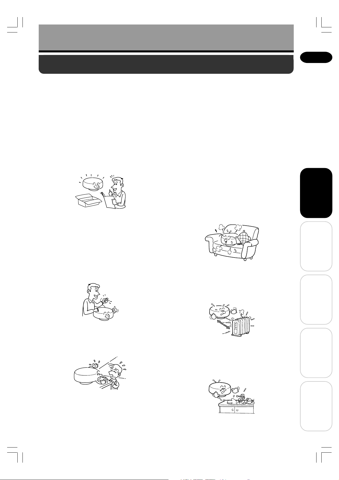
1. Read Owner's Manual
After unpacking this product, read the owner's
manual carefully, and follow all the operating and
other instructions.
2. Power Sources
This product should be operated only from the
type of power source indicated on the marking
label.
If you are not sure of the type of power supply to
your home, consult your product dealer or local
power company.
For products intended to operate from battery
power, or other sources, refer to the operating
instructions.
4. Ventilation
Openings in the cabinet are provided for
ventilation and to ensure reliable operation of the
product and to protect it from overheating, and
these openings must not be blocked or covered.
The openings should never be blocked by
placing the product on a bed, sofa, rug or other
similar surface. This product should not be
placed in a built-in installation such as a
bookcase or rack unless proper ventilation is
provided or the manufacturer's instructions have
been followed.
5. Heat
The product should be situated away from heat
sources such as radiators, heat registers, stoves,
or other products (including amplifiers) that
produce heat.
Before Using
Preparations
3. Source of Light
Do not look into the lens while the lamp is on.
The strong light from the lamp may cause
damage to your eyes or sight.
6. Water and Moisture
Do not use this product near water.
- for example, near a bath tub, wash bowl, kitchen
sink, or laundry tub; in a wet basement; or near a
swimming pool and the like.
Operations
Maintenance
Others
3
Page 4

Before Using
IMPORTANT SAFETY INSTRUCTIONS (Continued)
7. Cleaning
Unplug this product from the wall outlet before
cleaning. Do not use liquid cleaners or aerosol
cleaners.
Use a soft cloth for cleaning.
8. Power-Cord Protection
Power-supply cords should be routed so that
they are not likely to be walked on or pinched by
items placed upon or against them, paying
particular attention to cords at plugs,
convenience receptacles, and the point where
they exit from the product.
11. Object and Liquid Entry
Never push objects of any kind into this product
through openings as they may touch dangerous
voltage points or short-out parts that could result
in a fire or electric shock. Never spill liquid of
any kind on the product.
12. Do not place the product
vertically
Do not use the product in the upright position to
project the pictures at the ceiling, or any other
vertical positions. It may fall down.
9. Overloading
Do not overload wall outlets, extension cords, or
integral convenience receptacles as this can
result in a risk of fire or electric shock.
10. Lightning storms
For added protection for this product during a
storm, or when it is left unattended and unused
for long periods of time, unplug it from the wall
outlet. This will prevent damage to the product
due to lightning and power-line surges.
When lightning starts, do no touch this product,
the connection cable, or the power code plug.
13. Stack Inhibited
Do not stack other equipment on this product or
do not place this product on the other equipment.
Top and bottom plates of this product may
develop heat and damage other equipment.
14. Attachments
Do not use attachments not recommended by
the product manufacturer as they may cause a
hazard.
4
Page 5
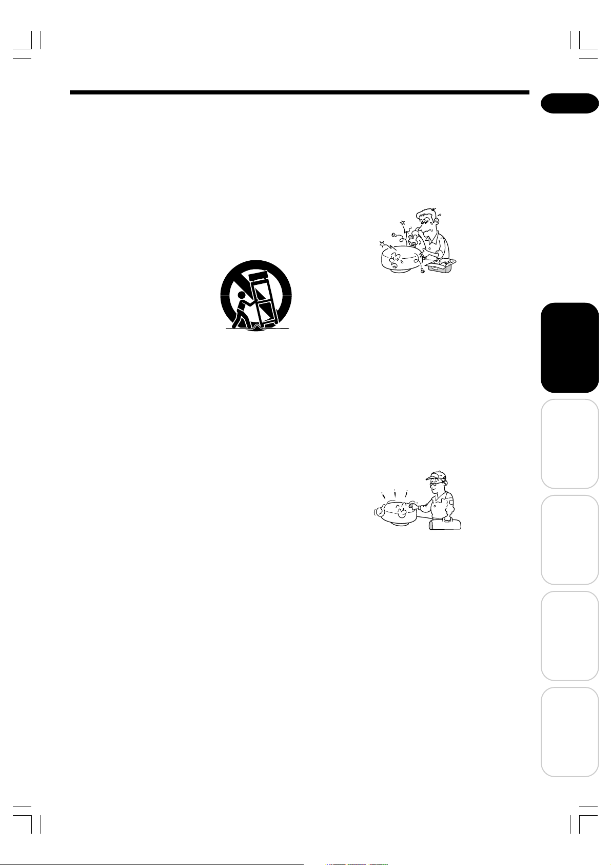
15. Accessories
Do not place this product on an unstable cart,
stand, tripod, bracket, or table. The product may
fall, causing serious injury to a child or adult, and
serious damage to the product. Use only with a
cart, stand, tripod, bracket, or table
recommended by the manufacturer, or sold with
the product. Any mounting of the product should
follow the manufacturer's instructions, and
should use a mounting accessory recommended
by the manufacturer. A
product and cart combination
should be moved with care.
Quick stops, excessive force,
and uneven surfaces may
cause the product and cart
combination to overturn.
S3125A
16. Damage Requiring Service
Unplug this product from the wall outlet and refer
servicing to qualified service personnel under
the following conditions:
a) When the power-supply cord or plug is damaged.
b) If liquid has been spilled, or objects have fallen
into the product.
c) If the product has been exposed to rain or water.
d) If the product does not operate normally by
following the operating instructions. Adjust only
those controls that are covered by the operating
instructions as an improper adjustment of other
controls may result in damage and will often
require extensive work by a qualified technician
to restore the product to its normal operation.
e) If the product has been dropped or damaged in
any way.
f) When the product exhibits a distinct change in
performance.
17. If glass components, including
lens and lamp, should break,
contact your dealer for repair
service.
This product incorporates glass components,
including a lens and a lamp. If such parts should
break, please handle with care to avoid injury
and contact your dealer for repair service. The
broken pieces of glass may cause to injury. In
the unlikely event of the lamp rupturing,
thoroughly clean the area around the projector.
18. Servicing
Do not attempt to service this product yourself as
opening or removing covers may expose you to
dangerous voltage or other hazards. Refer all
servicing to qualified service personnel.
19. Replacement Parts
When replacement parts are required, be sure
the service technician has used replacement
parts specified by the manufacturer or have the
same characteristics as the original part.
Unauthorized substitutions may result in fire,
electric shock, or other hazards.
(The only part the user should replace is the
lamp.)
20. Safety Check
Upon completion of any service or repairs to this
product, ask the service technician to perform
safety checks to determine that the product is in
proper operating condition.
21. Do not leave thermal-paper
documents or easily damaged
items on top of the unit or near
the air exhaust for long periods of
time.
The heat from the unit could erase the
information on the thermal paper, or cause
damage or warping.
Also, when you touch a metal object put near the
air exhaust, it could be hot and burn you.
English
Before Using
Preparations
Operations
Maintenance
5
Others
Page 6

Before Using
IMPORTANT SAFETY INSTRUCTIONS (Continued)
22. If smoke is coming out of this
product or you could smell
something, unplug the power
cord plug from the wall outlet.
Wait until you can confirm that no more smoke is
coming out, and then contact your product
dealer. Using this product without taking the
action mentioned above may cause a fire or an
electric shock.
LABEL LOCATIONS
MANUFACTURED;
SERIAL NO.
SERIAL NO. Label
23. If you wish to install the projector
to the ceiling, replace a lamp or
clean a filter of the ceiling
mounted projector and the like,
be sure to ask your product
dealer to do so.
Doing these things by yourself may cause injury
due to a fall, etc.
MODEL NO. /
RATING Label
TLP-ET1B
TLP-ET1E
TLP-ET1U
CAUTION Label
WARNING Label
WARNING LabelCAUTION Label
6
Page 7

Before Using
IMPORTANT PRECAUTIONS
Save Original Packing Materials
The original shipping carton and packing materials will come in handy if you ever have to ship your LCD projector. For
maximum protection, repack the set as it was originally packed at the factory.
Moisture Condensation
Never operate this unit immediately after moving it from a cold location to a warm location. When the unit is exposed
to such a change in temperature, moisture may condense on the crucial internal parts. To prevent the unit from
possible damage, do not use the unit for at least 2 hours when there is an extreme or sudden change in temperature.
Place and Manner of Installation
• Do not place the projector in hot locations, such as near heating equipment. Doing so could cause
malfunction, and shorten the life of the LCD panel.
• Avoid locations with oil or cigarette smoke. Doing so will dirty the LCD panel and other optical parts,
shortening their lives, and darkening the screen.
• Do not place slantwise in angle of 20° or more. Doing so could shorten the life of the lamp.
• Using this product near a TV or radio may cause interference to the images or audio sound. If this happens,
move it away from the TV or radio.
• Moving the projector from a low-temperature room to a high-temperature room may cause condensation on the
lens or internal parts of the product. If you continue to use it in that situation, the malfunction may result.
Ensure to wait until the condensation naturally disappears.
• In a high altitude location where air is thin, cooling efficiency of the projector is reduced. In this case, lower the
ambient temperature and use it.
Avoid Volatile Liquid
Do not use volatile liquids, such as an insect spray, near the unit. Do not leave rubber or plastic products
touching the unit for a long time. They will leave marks on the finish.
If cleaning with a chemically saturated cloth, be sure to follow the product's precautions.
English
Before Using
LCD Panel
The life of the LCD panel is limited. Take care over the points below so as to use the panel for years.
• To prolong the life of this panel, never fail to turn the power off when the panel is not in use and make sure that
the lamp has gone out. The state of the lamp being extinguished helps enhance the effect of energy saving.
• If the air filter is stained and is clogged up, the main unit inner temperature rises. As a result, the life of the
LCD is shortened and a malfunction may also occur.
Clean the air filter from time to time and replace it regularly. It is recommended that this replacement be done
at the time of replacing a lamp. (Ask a dealer where the unit was purchased or your nearby service station
about an air filter for replacement.)
In the spaces provided below, record the Model and Serial No. located at the bottom of your LCD projector.
Model No. Serial No.
Retain this information for future reference.
EXEMPTION CLAUSES
• Toshiba Corporation bears no responsibility in the case of damages arising from natural disaster (such as
earthquakes, lightning, etc.), fires not liable to Toshiba Corporation, operating by third parties, other accidents,
or use under abnormal conditions including erroneous or improper operation and other problems.
• Toshiba Corporation bears no responsibility for incidental damages (lost profit, work interruption, corruption or
loss of the memory contents, etc.) arising from the use of or the inability to use this unit.
• Toshiba Corporation accepts no liability whatsoever for any damages arising from not having followed the
descriptions in this Instruction Manual.
• Toshiba Corporation accepts no liability whatsoever for any damages arising from malfunctions arising from
combination with equipment or software that is not related to Toshiba Corporation.
Preparations
Operations
Maintenance
Others
7
Page 8

Before Using
OTHER CAUTIONS AND INFORMATIONS
Copyrights
Showing or transmitting commercial imaging software or broadcast or cable-broad casting programs with the purpose
of other than the personal and private viewing, including modifying images using the freeze or resize functions, or
displaying with the varying aspect ratio of the images, could violate the direct or indirect copyrights of the imaging
software or broadcast program, etc., if done without first consulting with the copyright holder. For this reason, please
take appropriate measures before performing one of the actions listed above, including obtaining a license from the
copyright holder.
Disposal
This product contains substances which are harmful to humans and the environment.
• Solder used in the internal parts contains the lead.
• The lamp contains inorganic mercury.
Please dispose of this product or used lamps in accordance with local regulations.
Trademarks
• VGA, SVGA, XGA, SXGA, UXGA are trademarks or registered trademarks of International Business Machines
Corporation.
• Windows is a registered trademark of Microsoft Corporation in the U.S. and other countries.
• “DCDi” and “TrueLife by Faroudja” are trademarks of Faroudja, a division of Genesis Microchip Corp.
Notational Conventions Used in This Manual
References to pages with related information are annotated as follows.
For example, if making a reference to page 36: (
p.36)
Checking the package contents
Please make sure that the following items are included in the box, along with the main unit. If any item is missing,
please contact the store immediately where you purchased the product.
(1) (2) (3)
(4) (5) (6)
■■ (1) Remote control
■■ (2) R03 (SIZE AAA) batteries for remote control
■■ (3) Owner’s Manual (this document)
■■ (4) Quick Reference
■■ (5) Power cord
■■ (6) AV cable
Note
The shape and number of supplied power cords vary depending on the product destination.
(see note)
8
Page 9

Before Using
CONTENTS
Before Using
SAFETY PRECAUTIONS ......................................... 2
IMPORTANT SAFETY INSTRUCTIONS ................... 3
LABEL LOCATIONS .................................................. 6
IMPORTANT PRECAUTIONS ................................... 7
EXEMPTION CLAUSES ........................................... 7
OTHER CAUTIONS AND INFORMATIONS ............. 8
Checking the package contents ................................8
CONTENTS .............................................................. 9
Selecting the Power Cord.......................................... 9
Preparations
Parts of the main unit .............................................. 10
Parts on the control panel and remote control ........ 11
Connection terminals .............................................. 12
Preparing and using the remote control ..................13
Placing the projector ............................................... 14
Connecting an input source device .........................15
Connecting a video device ................................ 15
Connecting a DVD player with component
video terminals .................................................. 16
Connecting a computer ..................................... 16
Operations
Turning the power on and off................................... 17
Before turning the power on ..............................17
Turning the power on ......................................... 18
Safety lock .........................................................18
Turning the power off ......................................... 19
Projecting ................................................................ 20
Easy setup using the EASY button ......................... 22
Changing the projection size ................................... 24
Changing the screen size........................................ 25
Cutting off the sound/Pausing the picture ............... 26
Cutting off the sound temporarily (Mute) ........... 26
Cutting off both the picture and sound
temporarily (Sleep) ............................................ 26
Pausing the picture (Freeze) ............................. 26
Switching the picture and sound ............................. 27
Setting the picture mode ................................... 27
Switching to surround sound ............................. 27
Enlarging the picture (Zoom) .................................. 28
Calling up a user profile .......................................... 29
Using the menus ..................................................... 30
How to use the menus ....................................... 30
Picture adjustment menu ................................... 32
Audio adjustment menu ..................................... 34
Default setting menu.......................................... 35
Status display menu .......................................... 36
User memory menu ...........................................37
Maintenance
Removing the tilt stand............................................ 39
Air filter cleaning ..................................................... 40
Lens and main unit cleaning ................................... 41
Lens cleaning .................................................... 41
Main unit cleaning ............................................. 41
Replacing air intake and exhaust fans, and
air filter ............................................................... 41
Lamp replacement .................................................. 42
Others
Trouble indications .................................................. 45
Before calling service personnel ............................. 46
Specifications ..........................................................47
List of general specifications ............................. 47
List of supported signals ................................... 48
Pin assignment of COMPUTER terminal .......... 49
Separately sold product ..................................... 49
English
Before Using
Preparations
Operations
Selecting the Power Cord
If your voltage is 220 to 240 V, use one of the following types of cable.
Plug
configuration
Use a 5A fuse which is approved by ASTA or BSI to
BSI362.
Always replace the fuse cover after changing the fuse.
Plug type
EURO
UK
Line voltage
220 – 240V
220 – 240V
Plug
configuration
Plug type Line voltage
Australian
240V
10A
Switzerland
240V
6A
North American
240V
15A
200 – 240V
200 – 240V
200 – 240V
Maintenance
Others
9
Page 10

Preparations
Parts of the main unit
(1)
(2)
(3)
(4)
(5)
Bottom
(10)
(9)
(10)
(1)
(6)
(7)
(4)
(8)
(15)
(11)
(12)
(14)
(13)
Name : Function
(1) Control panel : Operates the projector. (
(2) Focusing ring : Adjusts the screen focus. (
(3) Lens : Projects an expanded video image.
(4) Infrared remote sensor : Senses commands from the remote control. (
(5) Air exhaust : Expels air that has grown hot inside the unit.
(6) Speaker (Right) : Plays the sound input to AUDIO terminal (R).
(7) Connection terminals : Connect external devices. (
(8) AC IN socket : Connect the supplied power cord here. (
(9) Speaker (Left) : Plays the sound input to AUDIO terminal (L).
10
) Air intake : Draws in air from outside the unit.
(
11
) Air filter cover : Remove when cleaning the air filter. ( p.40)
(
12
) Anti-theft lock hole : Attach a security chain, etc. here.
(
13
) Tilt stand :
(
14
) Safety lock switch : Prevents the projector's power from being turned on accidentally. ( p.18)
(
15
) Lamp cover : Remove when replacing the lamp.( p.42)
(
Adjusts the vertical projection angle and the projector's horizontal tilt. ( p.20)
This tilt stand is removable. ( p.39)
p.11)
p.20)
p.13)
p.12, 15, 16)
p.17)
10
Page 11

Preparations
Parts on the control panel and remote control
Control panel Remote control
(12)
(8) (9) (10)
(11)
(6)
(4)
(3)
(16)
(1)
(2) (3) (5) (6) (7)
(17)
(20)
YPBPR/AV
Remote control
transmitter
(1)
(2)
(7)
(5)
(4)
(13)
(14)
(15)
(18)
(19)
English
Before Using
Name : Main function
(1) ON/STANDBY button : Turns the power on/off (standby). (
(2) INPUT buttons : Select input. ( p.21)
(3) MENU button : Displays menus. (
(4) Select buttons : Make menu selections and adjustments, etc. ( p.30)
In this manual, select buttons are represented by .
(5) OK button : Accepts the current selection, e.g., on a menu. ( p.31)
(6) EASY button : Displays the easy setting menu. ( p.22)
(7) USER button : Calls up a registered user profile. ( p.29)
(8) ON indicator : Shows whether the unit is powered on or standby. (
(9) LAMP indicator : Displays the current lamp mode. ( p.18, 19, 45)
(10) TEMP indicator : Lights when internal temperature is too high. ( p.45)
(11) FAN indicator : Displays the current cooling fan mode. ( p.18, 19, 45)
12
) LIGHT button : By pressing this button, the operation buttons light
(
up for about 10 seconds. Pressing the button again,
while the lights are on, turns off the lights. Pressing
another button while the lights are on turns on the
lights for another 10 seconds.
13
) EXIT button : Turns off the menu screen, etc. ( p.31)
(
(14) PICTURE MODE button : Selects a picture mode. ( p.27)
(15) SURROUND button : Selects a surround-sound effect mode. ( p.27)
16
) SIZE button : Selects a screen size. ( p.25)
(
(17) MUTE button : Cuts off the sound temporarily. ( p.26)
(18) SLEEP button : Cuts off the picture and sound temporarily. ( p.26)
(19) D.ZOOM button : Zooms in or out the image. ( p.28)
(20) FREEZE button : Pauses the image. ( p.26)
*
Although the center INPUT button is represented as “YPBPR/AV” in this manual, the button is represented as
BPR
“YP
” on the TLP-ET1U.
p.30)
p.18, 19)
p.17, 18, 45)
Buttons only on
the remote control
Preparations
Operations
Maintenance
Others
11
Page 12
Preparations
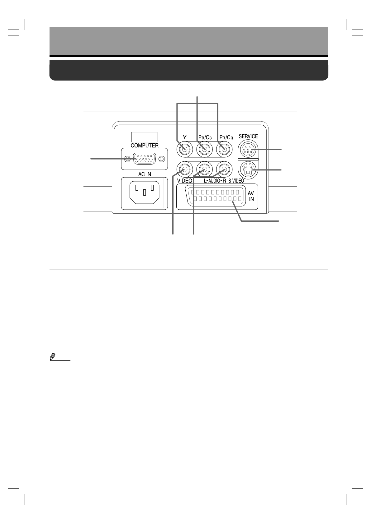
Connection terminals
(2)
(1)
(3)
(4)
(7)
(5)(6)
Name : Function
(1) COMPUTER terminal : Inputs RGB signals from a computer or other equipments.
(2) Y, P
(3) SERVICE terminal : Leave this unconnected. Used for repair purposes.
(4) S-VIDEO terminal : Inputs S-Video signals from a video device.
(5) AUDIO terminal : Inputs audio signals from a computer or video device.
(6) VIDEO terminal : Inputs video signals from a video device.
(7) AV IN terminal* : Inputs audio and video signals from a video device. The AV IN terminal
• Component video signals are abbreviated as Y/PB/PR in this manual. However, the projector supports signals
* Although the AV IN terminal is included in illustrations in this manual, the terminal exists only on the TLP-ET1B
B/CB, and PR/CR terminals : Input component video signals (Y/PB/PR) from a video device.
cannot receive S-Video signals.
Note
from a video device whose output signals are represented as Y/C
and TLP-ET1E. TLP-ET1U is not equipped with the AV IN terminal.
The AV IN terminal automatically identifies the RGB and composite signals.
Check the setting on the connected device as well.
B/CR as well.
12
Page 13

Preparations
Preparing and using the remote control
Loading batteries into the remote control
Point the remote control toward the projector's
Remove the battery cover.
infrared remote sensor, and press a button on the
remote control.
• Operating the projector from the front
Insert dry cell batteries.
Check the positive and negative terminals of
each battery to load it correctly.
• Operating the projector from the rear
Use two AAA (LR03 or R03) dry cell batteries.
Operating the remote control
Approx. 15°
Approx. 5m
English
Before Using
Put back the battery cover.
Approx. 15°
Approx. 5m
● Dry cell batteries
• Remove the batteries from the remote control when it is not used for an extended period of time.
• If the remote control stops working or its controlling range decreases, replace all the batteries with new ones.
● The remote control
• The remote control may fail to operate if the infrared remote sensor is exposed to bright sunlight or fluorescent
lighting.
• Do not drop or bang it.
• Do not leave it in hot or humid locations.
• Do not get it wet or place it on top of wet objects.
• Do not take it apart.
• In rare cases, ambient conditions could impede the operation of the remote control. If this happens, point the
remote control at the main unit again, and repeat the operation.
Preparations
Operations
Maintenance
Others
13
Page 14

Preparations
Placing the projector
• Always obey the instructions listed in IMPORTANT SAFETY INSTRUCTIONS when placing the unit.
• If you wish to mount the projector on the ceiling, be sure to ask your dealer to do so. Mounting the projector
on a ceiling requires special ceiling brackets (sold separately) and specialized knowledge. Improper
mounting could cause the projector to fall, resulting in an accident.
• If you wish to mount the projector on the ceiling, remove the tilt stand attached to this unit. Mounting the
projector with the tilt stand on the ceiling could cause it to fall, resulting in an accident.
• If the projector is ceiling-mounted, install the breaker for turning off the power in case of emergency. Let
everyone involved with the use of the projector know that fact.
Determine the placement style.
As shown in the figures below, this unit can be placed in four different styles.
The factory setting is “Front” and “Standard.” Set “Projection mode 1” and “Projection mode 2” in the
“Default setting” menu (see
“Front” “Standard” “Rear” “Standard”
p.35) in accordance with your needs.
“Front” “Ceiling” “Rear” “Ceiling”
Determine the projection distance and place the unit.
Determine the projection distance from the lens to the screen to obtain the desired screen size. (The
screen sizes listed below are approximate values for a full-size image projected with no keystone
adjustment.)
The screen size decreases as the lens comes closer to the screen; it increases as the lens goes away
from the screen.
Screen
As seen from above
°
90
As seen from the side
Lens center
Screen size
Inches/
vertical×horizontal (m)
32 (0.4 ×0.71)
40 (0.50×0.89)
60 (0.75×1.33)
80 (1.00×1.77)
100 (1.25×2.22)
120 (1.5 ×2.66)
Projection
distance L (m)
0.74
1.00
1.51
2.03
2.54
3.04
14
°
90
L
“L” is the lens-to-screen distance (m) ranging from
approximately 0.74 to 3.04 m.
Reference equation
L (projection distance) =
Projection size (inches) – 0.9317
39.039
Page 15

Preparations
Connecting an input source device
Before connection
• Read the owner’s manual of the device to connect to the projector.
• Turn off the power of both devices before connecting.
Connecting a video device
■ Using the AV or S-Video cable
(Red)(White)(Yellow)
AV cable
(supplied)
Red
To audio output(R)
White
To audio output(L)
Yellow
To video output
To S-Video output
S-Video cable
(not supplied)
English
Before Using
VCR
Note
•
Use the AV cable or S-Video cable to connect the input device to this unit. When using the S-Video cable, also use an
audio cable such as the AV cable to connect the audio input from the video device to the AUDIO terminals on the unit.
■ Using the SCART cable
SCART cable*
(not supplied)
To SCART
terminal
VCR
Preparations
Operations
Maintenance
Others
* The TLP-ET1U cannot use the SCART cable for connection since it has no AV IN terminal.
15
Page 16

Preparations
(Red)(Blue)(Green)
To component video output
Y(Green)
P
B
(Blue)
P
R
(Red)
(Red)(White)
DVD player
To audio outputs
White (L)
Red (R)
Component
video cable
(not supplied)
Audio cable
(not supplied)
Connecting an input source device (Continued)
Connecting a DVD player with component video terminals
16
Connecting a computer
• Some types of computer cannot be connected to or used with this projector.
Check the computer for an RGB output terminal, supported signal, and so on. (See
(Red)(White)
RGB cable
(not supplied)
To RGB output
Computer
Audio cable
(not supplied)
• Connect this cable
to use the projector’s
speaker.
To audio output
Note
• Moving pictures played with a DVD software player on a computer may look unnatural when projected by this
projector, but it is not a malfunction.
p.47.)
Page 17

Operations
Turning the power on and off
Before turning the power on
Connect the power cord.
q Insert the power cord connector into the AC IN socket on the
projector.
w Insert the power cord plug into a wall or other power outlet.
When the power cord is plugged in, the ON indicator comes on in
orange, indicating that the unit is on standby.
(Supplied) Power cord
connector
(Orange)
Remove the lens cover.
Be sure to remove the lens cover when the power is turned on. If it is left
on, it could become deformed due to heat.
English
TEMP FANLAMPON
Lit
Before Using
LCD Panels
LCD panels wear out. In order to prolong the lifetime of your LCD panel, take the following
precautions:
• In order to extend the lifetime of the LCD panel, always turn off the power when not in use, and make sure that
the lamp is off. Keeping the lamp off is also very effective at saving electricity.
• If the air filter becomes dirty and clogged, the projector’s internal temperature will rise, shortening the lifetime of
the LCD panel and causing malfunctions. Clean the air filter from time to time (see
periodically. Contact the store where you purchased your projector, or your local Service Station for replacement of the air filters.
The projector’s LCD panel is made using extremely advanced technology, but there may be black
spots (pixels that do not light) or bright spots (pixels that are constantly lit) on the panel. Please
note that these are not malfunctions.
p.40), and replace it
Preparations
Operations
Maintenance
Others
17
Page 18

Operations
Turning the power on and off (Continued)
Turning the power on
Press the ON/STANDBY button.
Remote control
•
Do not look into the lens during operation. Doing so could damage your vision.
• Families with children should be particularly careful.
Control panel
The power is turned on, and three (ON,
LAMP, and FAN) indicators come on in
green. After a moment, the startup screen
appears.
TEMP FANLAMPON
(Green)
(Green)
Lit
Lit
(Green)
Lit
• Do not block the air intake or exhaust. Doing so could cause a fire due to
internal overheating.
• Do not place your hands, face, or other objects near the air exhaust. Doing
so could cause burns or deform, discolor, or break the object.
Notes
• The startup screen will disappear after a moment. You can dismiss the startup
screen before this by performing any operation.
• After the startup screen disappears, the language menu is displayed when you
use the projector for the first time after purchase. (See
• Turning the power on starts the cooling fan running with operating sound.
Safety lock
You can prevent the projector’s power from being turned on accidentally.
Set the safety lock switch on the bottom of the main unit to ON.
In standby mode with the safety lock switch set to ON, the ON indicator lights in orange
and in green alternately.
Once you have set the safety lock switch to ON, you have to hold down the ON/
STANDBY button for at least two seconds to turn on the power of the projector. Other
operations are the same.
p.20.)
18
Page 19

Turning the power off
Press the ON/STANDBY button.
Remote control
Control panel
A message appears on the screen,
confirming that you wish to shut off the
power. This message will disappear after
a moment. (This operation is no longer valid
after the message disappears.)
Press the ON/STANDBY button again.
Remote control
Control panel
The screen is turned off, but the internal
cooling fan continues to operate for a short
while. Then, the projector goes into standby
mode.
English
Before Using
Cooling in progress
(Orange) (Green)
Flashing
Cooling completed
FANTEMPLAMPON
(Green)
During cooling, the LAMP indicator flashes.
In this state, the power cannot be turned
back on. In addition, unplugging the power
cord in this state will shorten the life of the
lamp.
The LAMP and FAN indicators go off, and
the projector goes into standby mode.
FANTEMPLAMPON
(Orange)
(Off) (Off)
Note
• The projector consumes about 1 W (AC 100 - 120 V) or 3 W (AC 220 - 240 V) of power in standby. You should
unplug the power cord if you will not use the projector for an extended period.
PRECAUTIONS
• Before unplugging the power cord, make sure that the LAMP indicator is off. Unplugging the power cord to cut
off the power while the projector is running or being cooled will shorten the life of the lamp. However, please
unplug the power cord if the projector locks up or acts abnormally.
• If the power cord was unplugged before cooling was completed, give the lamp sufficient time to cool down
before plugging it back in. If the lamp overheats, it may fail to light, and its lifetime will be shortened.
• Before turning the power off, turn down the volume if possible.
Preparations
Operations
Maintenance
Others
19
Page 20

Operations
Projecting
Turn on the power.
Turn on the power by following the instructions in “Turning the power on”
(see
p.18).
Adjust the projection angle.
Adjust the angle of the main unit as you like.
• The angle can be adjusted within a
range of approximately ±10° in a
horizontal position.
Adjust the screen focus.
Adjust the focus using the focusing ring.
Select the language (when using the unit for
the first time).
English
Fran çais
Deutsch
Italiano
Español
Português
Remote control
Remote control
• The language can also be set via the “Language” option in the “Default
• This owner’s manual assumes that English has been selected.
................
..............
..............
................
...............
..................
setting” menu (see
English
French
German
Italian
Spanish
............
Portuguese
Japanese
Control panel
Control panel
When the projector is used for the first time
after purchase, the menu for selecting the
language for on-screen messages and
menu items is displayed in English.
q Use the and buttons to
select the desired language.
w Press the OK button to accept the
language setting.
The message for setup confirmation is
displayed in a selected language.
p.35).
20
Page 21

YPBPR/AV
Place the connected device in operating status.
Turn on the connected device such as a video device.
Select the connected input.
(Using the remote control)
Press an INPUT button (VIDEO/S, YPBPR/
YPBPR/AV
• Pressing the VIDEO/S button switches the projected picture between
the VIDEO and S-VIDEO inputs.
• Pressing the YP
B/PR and AV inputs. (This function is available only for the TLP-
the Y/P
ET1B and TLP-ET1E.)
Video → S-video→ Y/PB/PR → AV → Computer
BPR/AV button switches the projected picture between
AV, or COMPUTER) to select the input.
The picture from the selected input will be
projected.
(Using the control panel)
Press the INPUT button on the main
unit to select the input.
Pressing the INPUT button switches the inputs
as shown below.
English
Before Using
• “AV” is available only for the TLP-ET1B and TLP-ET1E.
Adjust the volume with the ( ) and ( )
buttons.
Remote control
Notes
• Note that because of the lamp characteristics, the brightness of the lamp may fluctuate slightly.
• A lamp is a consumable supply. If the lamp is used for an extended period, images will appear dark, and the
lamp could burn out. This is characteristic of a lamp, and is not a malfunction.
• Although this projector supports a wide range of RGB signals (see
the number of pixels of the LCD panel of this projector will enlarge or compress the pictures, causing lack of
some information or affecting image quality.
•
With some models of computer having LCD displays or the like, displaying images simultaneously on the projector
and the monitor’s display may cause the images to be shown improperly. If this happens, turn off the computer’s
LCD display. For information on how to turn off the LCD display, see the owner’s manual of your computer.
• If a signal not supported by the projector is input, the icon will appear.
• If a no signal is being input from the connected device, the
change to blue and the TOSHIBA logo will appear.
• If no signal is being input for more than 10 minutes, the power will be automatically turned off and the unit will
be placed in the standby state.
• If an unavailable operation button is pressed, the
• The audio input to the Audio terminals is played regardless of the input source. (When the AV input is selected,
however, AV IN audio is played.)
Control panel
icon will appear.
The speaker volume can be adjusted when
an audio signal is being input.
p.48), any resolution signals that exceed
icon will appear. The screen color will also
Preparations
Operations
Maintenance
Others
21
Page 22

Operations
Easy setup using the EASY button
You can use the EASY button to configure frequently used adjustments and settings.
For any settings (adjustments) other than the settings (adjustments) described in this section, see “Using the
menus” (
p.30) to make the settings (adjustments) as required.
Press the EASY button.
Remote control
Control panel
Use the and buttons to select the menu
item you want to set or adjust.
Remote control
Control panel
The “Easy setting” menu appears.
Easy setting
Projection size
Keystone
Picture mode
Screen size
Up/down shift
Lamp power
Projection mode 1
100%
0
Standard
Zoom
0
Standard
Front
The selected item can now be set or
adjusted.
Easy setting
Projection size
Keystone
Picture mode
Screen size
Up/down shift
Lamp power
Projection mode 1
100%
0
Standard
Zoom
0
Standard
Front
Adjust
Adjust
22
Use the and buttons to set or adjust the
selected item.
Remote control
Control panel
Set or adjust the selected item by referring
to the table on
Some items need to be set with
p.23.
and
buttons after pressing OK button.
Repeat steps 2 and 3 above to complete
settings or adjustments, then press the EASY
button.
Remote control
Control panel
The menu disappears.
• You can also dismiss the menu by
pressing the EXIT button on the remote
control.
Page 23

Item Description
Projection size Change the picture area size on the screen.
Use
to decrease the projection size or to increase it.
See p.24 for details.
Keystone Correct the keystone (trapezoid) distortion of the screen. (For keystone
distortion, see “Correction of keystone distortion” described below.)
Use to shrink the lower part or to shrink the upper part.
Picture mode Switch to the picture mode suitable for movie or game screens.
Press OK button first, and then set the item with
Standard/Cinema/Game
Screen size Switch the screen size.
Press OK button first, and then set the item with
Full/Theater wide/4:3/Zoom
See p.25 for details.
Up/down shift Scroll the screen up or down, for example, when subtitles are outside the picture
area. (Adjustable only when the screen size is “Zoom”.)
Down Up
Lamp power Lower lamp power to decrease the cooling fan noise.
Standard/Low
Setting lamp power “Low” makes the screen a little darker but makes the cooling fan
noise quieter.
Projection mode 1 Select whether the placement style is front or rear projection.
Front/Rear
and buttons.
and buttons.
English
Before Using
Notes
• “Projection size” can also be adjusted by using ( ) and ( ) buttons, on the remote control or main unit.
(See
• Decreasing the projection size may affect image quality slightly. (It does not change the menu size.)
• “Picture mode” can also be set via the PICTURE MODE button on the remote control or the “Picture adjust-
ment” menu. (See
• “Screen size” can also be set via the SIZE button on the remote control or the “Default setting” menu. (See
• “Keystone”, “Up/down shift”, “Lamp power”, and “Projection mode 1” can also be adjusted via the “Default
setting” menu. (See p.35.)
• The items set and adjusted on the “Easy setting” menu are saved when the power is turned off with the ON/
STANDBY button. They are not saved if power is disconnected by unplugging the power cord or by a power
failure.
p.24.)
p.27, 32.)
p.25, 35.)
● Correction of keystone distortion
When the tilt stand (see p.20) is used to change the projection angle, the picture will undergo keystone
(trapezoid) distortion.
The projector is capable of correcting this keystone distortion.
Before correction After correction
• Depending on the amount of keystone adjustment and the content of images, some information may be lost
or the picture quality may suffer. Keystone adjustment will not change the shape of the menus.
Preparations
Operations
Maintenance
Others
23
Page 24

Operations
Changing the projection size
You can change the projection size (picture area size on the screen).
Press the ( ) button.
Remote control
Press the ( ) button.
Remote control
Control panel
Control panel
The adjustment bar is displayed.
Pressing the
projection size.
The adjustment bar is displayed.
Pressing the
projection size.
You cannot make the image larger than its
original size.
( ) button decreases the
( ) button increases the
24
Notes
• The “Projection size” can also be adjusted via the “Easy setting” menu. (See
p.22.)
• Decreasing the projection size may degrade the images more or less.
Page 25

Operations
Changing the screen size
The projection screen of this projector is 16:9, though the screen size can be changed depending on the input signal.
Press the SIZE button on the remote control.
Pressing the SIZE button for the first time displays the
current screen size. Pressing the SIZE button while the
current screen size is displayed cycles the screen size
through the following options:
Full → Theater wide → 4:3 → Zoom
Full : This mode is best for squeeze-signal video images.
Theater wide:
4:3 : This mode is best for 4:3-signal video images on the 4:3-
Zoom :
Input signal Projection screen
4:3 signal
This mode is best for 4:3-signal video images on the wide screen.
size screen.
This mode is best for video images of letter-box or cinema signals.
Full Theater wide (O)
→
English
Before Using
Squeeze signal
Zoom
Full (O) Theater wide
Zoom
↑↓
←
→
↑↓
4:3 signal
4:3 signal
Notes
• The screen size cannot
be changed when the
16:9 signal is input.
• You cannot select
“Theater wide” and
“Zoom” when the input is
COMPUTER.
An adjustment bar of “Up/
•
down shift” is displayed in
“Zoom” mode and you can
make the adjustment (See
p. 23, 35.)
• If you use this function on
commercial video software or on a broadcast or
cable broadcast except
for the purpose of your
private viewing and
listening, it may infringe
the copyright protected by
the copyright laws. (O): Optimum screen size
Letter box signal
Cinema signal
Full Theater wide
Zoom (O)
Full Theater wide
Zoom (O)
↑↓
↑↓
←
→
4:3
←
→
4:3
←
Preparations
Operations
Maintenance
Others
25
Page 26

Operations
Cutting off the sound/Pausing the picture
Cutting off the sound temporarily (Mute)
You can turn off the projector’s sound temporarily.
Press the MUTE button on the remote control.
The sound are cut off.
Pressing the MUTE button again cancels the Mute
function and releases the sound.
Notes
• The icon will appear while Mute is in effect.
• Operating any other function cancels the muting.
• It can also be canceled by pressing the EXIT button on the remote control.
Cutting off both the picture and sound temporarily (Sleep)
You can turn off both the projector’s picture and sound temporarily.
Notes
• The icon will appear while Sleep is in effect.
• Operating any other function cancels the sleeping.
• It can also be canceled by pressing the EXIT button on the remote control.
Pausing the picture (Freeze)
You can pause the picture being projected.
Notes
• The icon will appear while Freeze is in effect.
•
The Zoom function can be used on a frozen image to enlarge it. The freeze is canceled by
performing any other operation or by pressing the EXIT button on the remote control.
• Even if an image is frozen on the projector, the pictures are running on the
video or other device. Audio continues to be output as well.
• If you use this function on commercial video software or on a broadcast or
cable broadcast except for the purpose of your private viewing and listening, it
may infringe the copyright protected by the copyright laws.
26
Press the SLEEP button on the remote control.
The picture and sound are cut off.
Pressing the SLEEP button again cancels the Sleep
function and releases the picture and sound.
Press the FREEZE button on the remote control.
The picture pauses.
Pressing the FREEZE button again cancels the Freeze
function.
Page 27

Operations
Switching the picture and sound
Setting the picture mode
You can switch the picture mode suitable for the movie or game screen.
Press a PICTURE MODE button (STD./CINEMA/
GAME) on the remote control.
The projector will switch to the selected picture
mode.
STD. : Standard picture mode
CINEMA : Suitable for watching movies
GAME : Suitable for game screens
• Select the desired picture mode.
English
Before Using
Switching to surround sound
Surround sound reproduces deep and expanded atmospheres through natural, realistic sensations.
Press the SURROUND button on the remote
control.
Pressing the SURROUND button for the first time displays
the current surround mode. Pressing the SURROUND
button while the current surround mode is displayed
cycles the sound through the following options:
→ → →
: Surround (Off)
: Surround (Soft)
: Surround (Hard)
: Turns a mono signal into quasi-stereo.
Notes
• Surround sound can also be set via the “Audio adjustment” menu (see
p.34).
• Surround sound effect depends on each input source.
• Selecting with a stereo source may lose its true-stereo sensation.
Preparations
Operations
Maintenance
Others
27
Page 28

Operations
Enlarging the picture (Zoom)
You can enlarge (zoom in) the image being projected.
Press the D.ZOOM button on the remote
control.
Pressing the D.ZOOM button increases the zoom
magnification.
To decrease the zoom magnification, press
the D.ZOOM
button on the remote control.
Pressing the D.ZOOM button decreases the zoom
magnification.
(The image cannot be shrunk to less than its original size.)
Use the , , , and buttons to move the
enlarged area.
Notes
• The icon will appear while Zoom is in effect.
• An enlarged image can be frozen using the FREEZE button. The Zoom function on the frozen image can
also be used.
• Since the enlargement is performed by digital processing, enlarging will cause the image to appear jagged.
• Rarely, the picture could become garbled while the enlarged area is being moved.
• Operations other than Freeze will cancel the zooming.
• It can also be canceled by pressing the EXIT button on the remote control.
• If you use this function on commercial video software or on a broadcast or cable broadcast except for the
purpose of your private viewing and listening, it may infringe the copyright protected by the copyright laws.
28
Page 29

Operations
Calling up a user profile
You can easily switch the projector to the settings saved on the “User memory” menu (see p.37).
Press the USER button.
Remote control
Control panel
The “User memory call” menu will appear.
User memory call
A/V reset
Call
Pressing the USER button again will
dismiss the “User memory call” menu.
Pressing the EXIT button on the remote
control will also dismiss the “User memory
call” menu.
English
Before Using
Use the and buttons to select the
settings saved (as a user profile) in user
memory, then press the OK button.
Remote control
Control panel
The projector is switched to the selected
user memory settings.
Selecting “A/V reset” resets only the items
in the “Picture adjustment” and “Audio
adjustment” menus to their default settings.
Preparations
Operations
Maintenance
29
Others
Page 30

Operations
Using the menus
How to use the menus
You can call up on-screen menus, and conduct a number of adjustments and settings using the operation
buttons on the remote control and on the main unit’s control panel.
For details on each adjustment and setting item, see the corresponding page.
Menus shown below are only for operation instructions and might be different from the actual display.
Picture adjustment
( p. 32)
Audio adjustment
( p. 34)
Press the MENU button.
The menu screen will be displayed.
e.g.
Picture adjustment
Use the and buttons to select a desired
menu icon, then press the
The cursor moves to the corresponding adjustment/setting item.
e.g.
Default setting
( p. 35)
Menu
Contrast
Brightness
Sharpness
TrueLife by Faroudja
Noise reduction
Picture mode
Color
Tint
R-gain
G-gain
B-gain
Video mode
Menu
Status display
( p. 36)
Standard
Auto.
User memory
( p. 37)
ExitEnter
Menu icons
and indicate you can
select menu icons.
0
0
0
0
0
Adjustment/setting items and
0
their settings
0
0
0
0
button.
Menu icons
30
Picture adjustment
Standard
Auto.
0
Contrast
0
0
0
0
0
0
0
0
0
and indicate you can change
the adjustment and setting item.
Adjust
Page 31

0
0
0
0
0
Standard
0
0
+0
0
0
Auto.
Picture adjustment
Auto.
Use the and buttons to
All reset
Will reset all the items in the menu.
Are you sure?
No
Ye s
Execute
select a desired adjustment
or setting item.
Item
Picture adjustment
0
0
0
0
0
Standard
0
0
0
0
0
Auto.
Sharpness
e.g.
(When an adjustment item is selected)
Use the and buttons
to adjust the selected item.
Picture adjustment
e.g.
Standard
Auto.
0
0
+2
Sharpness
0
0
0
0
0
0
0
Adjustment bar
and indicate you can
adjust the current item.
(When a setting item is selected: 1)
Use the and buttons
to set the selected item.
Picture adjustment
e.g.
Standard
Auto.
0
0
0
0
0
Picture mode Standard Cinema Game
0
0
0
0
0
Selection items
and indicate you
can select options for
the current item.
Adjust
Adjust
Select
(When a setting item is selected: 2)
Press the OK button
if an
adjustment bar or selection items
did not displayed on the Step 3
A selection list will appear.
Use the and buttons
to set the item.
e.g.
Selection list
and indicate you
can select options for the
current item.
Press the OK button.
The selection list will disappear.
(When an execution item is selected)
Press the OK button if an
adjustment bar or selection items
did not displayed on the Step 3.
A confirmation dialog box will appear,
asking you whether to execute the item.
e.g.
To execute the item, select
“Yes” using the
and
buttons, then press the OK
button.
English
.
Before Using
Preparations
Operations
Maintenance
Notes
• Pressing the MENU button with a menu screen displayed returns you to the previous menu screen.
• Pressing the EXIT button on the remote control dismisses the menu screen.
• The items adjusted and set with these menus are saved when the power is turned off with the ON/STANDBY
button. They are not saved (except the user memory and lamp time settings) if power is disconnected by
unplugging the power cord or by a power failure.
Others
31
Page 32

Operations
Using the menus (Continued)
Picture adjustment menu
Use this menu to adjust image-related items.
e.g.
Menu
ExitEnter
Press the MENU button.
Picture adjustment
Contrast
Brightness
Sharpness
TrueLife by Faroudja
Noise reduction
Picture mode
Color
Tint
R-gain
G-gain
B-gain
Video mode
Item Description
Contrast Adjust picture contrast.
Brightness Adjust picture brightness.
Sharpness Adjust picture sharpness.
TrueLife by Enhance uneven edges, for example, of
Faroudja skins without highlighting outlines. Yes Yes Yes Yes –
Noise reduction Adjust noise reduction on the screen.
Picture mode Switch the picture mode using and .
Color Adjust picture color density.
Tint Adjust picture tint (hue).
R-gain Adjust the base level of red in pictures.
G-gain Adjust the base level of green in pictures.
B-gain Adjust the base level of blue in pictures.
0
0
0
0
0
Standard
0
0
0
0
0
Auto.
Lower Higher
Darker Brighter
Softer Sharper
Lower Higher
Lower Higher
Standard/Cinema/Game
Lighter Deeper
Reddish Greenish
Lower Higher
Lower Higher
Lower Higher
Use the and buttons to select
the picture adjustment menu icon
[
], then press the button.
Use the and buttons to select an
item you want to adjust, then adjust it
according to the table shown below.
Remote control
Control panel
Video S-video Y/PB/PR AV Computer
Ye s Ye s Ye s Ye s Yes
Ye s Ye s Ye s Ye s Yes
Ye s Ye s Ye s Ye s –
Ye s Ye s Ye s
Ye s Ye s Ye s Ye s –
Ye s Ye s Ye s Ye s –
*2
Ye s
Ye s Ye s Ye s Ye s Yes
Ye s Ye s Ye s Ye s Yes
Ye s Ye s Ye s Ye s Yes
Ye s
*2
*1
Ye s –
– Ye s –
*1 “Noise reduction” can be adjusted only when the signal formats are 480i and 576i.
*2 “Tint” can be adjusted only when the video modes are NTSC and NTSC4.43.
32
Page 33

Item Description
Auto setting Adjust items, such as the sampling phase,
depending on the type of input signal. ––––Ye s
Press the OK button.
Phase Adjust with and to minimize flicker. ––Ye s – Ye s
Frequency Adjust with and to minimize periodic
patterns and flickering when many vertical ––––Ye s
lines appear on the screen.
H-position Adjust the horizontal position of the picture
screen. ––––Ye s
Move left Move right
V-position
Clamp 1) Press the OK button.
Signal format Set the Y/PB/PR signal DTV format.
Video mode Set the VIDEO and S-VIDEO color system.
Adjust the vertical position of the picture screen.
Move up Move down
2) Use
Adjust the position of the clamp pulse.
Adjust the width of the clamp pulse.
1) Press the OK button.
2) Select one from the displayed list with
Auto:
Automatically identifies the type of input signal.
If this fails, select one from the following:
480i(525i)@60/480p(525p)@60/
576i(625i)@50/576p(625p)@50/
720p(750p)@60/720p(750p)@50/
1080i(1125i)@60/1152i(1250i)@50/
1035i(1125i)@60/1080i(1125i)@50
1) Press the OK button.
2) Select one from the displayed list with
Auto:
Automatically identifies the type of input signal.
If this fails, select one from the following:
NTSC/PAL/SECAM/PAL-N/PAL-M/PAL60/NTSC4.43
or to select Clamp 1 or 2.
Clamp 1:
Down Up
Clamp 2:
Shorter Longer
and , then press the OK button.
and , then press the OK button.
Video S-video Y/PB/PR AV Computer
––––Ye s
––––Ye s
––Ye s ––
Ye s Ye s – Ye s –
English
Before Using
Preparations
Operations
Notes
• Items can be adjusted/set (marked with “Ye s ”) or cannot (marked with “–”) depending on each type of input.
• Pressing the EXIT button on the remote control dismisses the menu screen.
Maintenance
Others
33
Page 34

Operations
Using the menus (Continued)
Audio adjustment menu
Use this menu to adjust audio-related items.
e.g.
Menu
ExitEnter
Press the MENU button.
Audio adjustment
Volume
Treble
Bass
Balance
Surround
10
0
0
0
Use the and buttons to select
the audio adjustment menu icon [
then press the
button.
Use the and buttons to select an
item you want to adjust, then adjust it
according to the table shown below.
Remote control
Item Description
Volume Adjust the volume of sound.
Down Up
Treble Adjust the higher frequency range of audio output.
Weak Strong
Bass Adjust the lower frequency range of audio output.
Weak Strong
Balance Adjust the balance in volume level between the left and right speakers.
Increase left Increase right
Surround Select a surround sound effect mode with and .
/ / /
: Surround (Off)
: Surround (Soft)
: Surround (Hard)
: Turns a mono signal into quasi-stereo.
Control panel
],
Notes
• Pressing the EXIT button on the remote control dismisses the menu screen.
• On rare occasions, turning up the volume or bass may cause the projected screen to flutter, depending on
the input audio signal level. If this is the case, turn it down.
34
Page 35

Default setting menu
Use this menu to make settings such as the placement style (projection mode).
e.g.
Menu
ExitEnter
Press the MENU button.
English
Default setting
Keystone
Screen size
Up/down shift
Lamp power
Projection mode 1
Projection mode 2
Language
NTSC mode
All reset
Lamp time reset
Item Description
Keystone Correct the keystone (trapezoid) distortion of the screen.
Screen size Set the screen size mode.
Up/down shift Scroll the screen up or down, for example, when subtitles are outside the picture area.
Lamp power Select lamp power with and .
Projection mode 1 Select projection mode 1 with and , according to the projector’s placement style.
Projection mode 2 Select projection mode 2 with and , according to the projector’s placement style.
Language Select the language for on-screen menus and messages.
NTSC mode Set with and .
All reset Reset all of the adjustment and setting items to the defaults.
Lamp time reset Reset the lamp timer. (See p.44)
0
Zoom
0
Low
Front
Standard
English
US
Shrinking lower part Shrinking upper part
1) Press the OK button.
2) Select one from the displayed list with and , then press the OK button.
(“Theater wide” and “Zoom” cannot be selected when the input is COMPUTER.)
This item can also be set with the SIZE button on the remote control. (See p.25.)
(Adjustable only when the screen size is “Zoom”.)
1) Press the OK button.
2) Select one from the displayed list with and , then press the OK button.
English/Français/Deutsch/Italiano/Español/Português/
US : NTSC (US) mode
JAPAN: NTSC (JAPAN) mode
1) Press the OK button.
2) In the dialog box displayed, use or to select whether to execute this function, then
press the OK button.
Use the and buttons to select the
default setting menu icon [
press the
button.
Use the and buttons to select an
item you want to set, then set it
according to the table shown below.
Remote control
Full/Theater wide/4:3/Zoom
Down Up
Standard/Low
Front/Rear
Standard (floor-mounted)/Ceiling
Control panel
Note
• Pressing the EXIT button on the remote control dismisses the menu screen.
], then
Before Using
Preparations
Operations
Maintenance
Others
35
Page 36

Operations
Using the menus (Continued)
Status display menu
This menu displays information about the input signal, lamp use time, etc.
e.g.
Menu
Exit
Press the MENU button.
Status display
Input
Mode name
H-resolution
V-resolution
H-frequency
V-frequency
Sync
Lamp time
Version
Item Description
Use the and buttons to select
the Status display menu icon [
The “Status display” menu will appear.
Remote control
Control panel
Video S-video Y/PB/PR AV Computer
].
Input Displays the input source name. Yes Yes Yes Yes Yes
Mode name Displays the RGB signal mode name.
*1
––––Ye s
H-resolution Displays the horizontal resolution (in dots). ––––Ye s
V-resolution Displays the vertical resolution (in dots). ––––Ye s
H-frequency Displays the horizontal sync frequency. ––––Ye s
V-frequency Displays the vertical sync frequency.
Sync Displays the sync signal polarity.
*2
*3
––––Ye s
––––Ye s
Signal format Displays the Y/PB/PR signal format. ––Ye s ––
Video mode Displays the video signal color system. Yes Yes – Ye s –
Lamp time Displays the total time of lamp use.
Version Displays the firmware version.
*4
*5
Ye s Ye s Ye s Ye s Ye s
Ye s Ye s Ye s Ye s Ye s
*1 : The mode of supported RGB signals ( p.48) is shown.
*2 : Same as the refresh rate of the computer signal.
*3 : Sync signal polarity shown as P (positive) or N (negative) for “H/V”.
*4 : Display “Lamp time” as a measure of when the lamp should be replaced. (Cannot be used as a counter of
guaranteed lamp time.)
*5:“Version” shows the version of the projector’s internal control program. This version is referred for customer
service, etc.
Notes
• Items can be displayed (marked with “Ye s ”) or cannot (marked with “–”) depending on each type of input.
• Pressing the EXIT button on the remote control dismisses the menu screen.
36
Page 37

User memory menu
Use this menu to register up to three sets of adjustments and settings made on the menu screen as user
profiles. You can call any of the user profiles later using the USER button. (See
p.29.)
Press the MENU button.
English
Use the or
Remote control
Control panel
button to select the user memory menu icon [ ].
Menu ExitEnter
User memory
User1
User2
User3
USER MEMORY1
USER MEMORY2
USER MEMORY3
The user memory registration menu
will appear.
Press the button.
Remote control
Control panel
Menu
User memory
USER MEMORY1
USER MEMORY2
USER MEMORY3
User1
Setting
The user memory select menu will
appear.
Use the or button to select the user memory number with
which you want to register the current settings, then press the OK
button.
Remote control
Control panel
User memory
Registration Cancel
The icon select menu will appear.
Before Using
Preparations
Operations
Press the OK button, use the , , , or button to select a
desired icon, then press the OK button.
Remote control
Control panel
User memory
Registration Cancel
The cursor will move to the user
memory registration icon.
(Continued)
Maintenance
Others
37
Page 38

Operations
Registration Cancel
User memory
User1
Menu
Setting
User memory
LIVING
USER MEMORY2
USER MEMORY3
Registration Cancel
User memory
Using the menus (Continued)
Press the button, move the cursor to the user memory
registration name, then press the OK button.
Remote control
Control panel
The user memory name input
screen will appear.
Use the , , , and buttons to select each character you
want to enter, then press the OK button.
Remote control
Control panel
User memory
Registration Cancel
Press the OK button after
selecting each character.
To clear all the input characters,
select “
CA
button.
” and press the OK
When you finish entering characters, use the , , , and
buttons to select “
Remote control
Control panel
”, then press the OK button.
OK
The cursor will be moved to the
user memory registration name.
Use the button to select “Registration”, then press the OK
button.
Remote control
Control panel
Notes
• To change a registered icon or user memory name, re-register it from the beginning.
• Pressing the EXIT button on the remote control will dismiss the menu screen.
The current settings are registered
in the selected user memory
number.
To return to the screen of Step 3,
select “Cancel” and press the OK
button.
38
Page 39

Maintenance
Removing the tilt stand
Do not remove the tilt stand unless when you replace the lamp or mount the projector on a ceiling. Removing
the tilt stand leaves the projector unstable and may block the air intake at the bottom. Usually, the projector
must be used with the tilt stand.
PRECAUTIONS
• Before removing the tilt stand, be sure to turn off the power and unplug the power cord.
Place the unit upside down.
Turn the projector over and place it carefully. It is
recommended to lay a soft cloth, such as a thick towel,
under the unit to prevent it from shaking or getting
scratched.
English
Before Using
Loosen the three screws.
Detach the tilt stand.
1
2
Position the tilt stand where you can see three screws in
the centers of their respective screw holes. Loosen the
screws by turning them counterclockwise several times.
Preparations
Operations
Hold the tilt stand with both hands, turn it
counterclockwise, then lift it to remove.
Maintenance
To put the tilt stand back in place, take the above steps in reverse order. At this time, always make sure that
the three screws have been tightened.
Others
39
Page 40

Maintenance
Air filter cleaning
The air filter prevents dust and debris from getting inside the projector. Never run the projector with the filter
removed. The air filter should be cleaned regularly.
• The
hours, this message is displayed for 30 seconds when the image is displayed for the first time after the power is
turned on. The message will be dismissed with any operation.)
• Check out the filter and, if any debris is found, use the following procedure for cleaning.
icon message, “Check the air filter for dirt,” is displayed every 100 hours. (If the usage time exceeds 100
• Request cleaning and maintenance of a ceiling-mounted unit to your projector dealership.
Unplug the power cord.
Remove the air filter.
Pull out the air filter by taking the catch shown in the figure with
your fingertips.
After turning the projector over, place it carefully. It is
recommended to lay a soft cloth, such as a thick towel, under the
unit to prevent it from shaking or getting scratched.
Clean the filter.
Carefully remove the dust and dirt from the air filter with a
vacuum cleaner or the like.
Replace the air filter.
Notes
• Allowing dirt and dust to build up in the air filter will worsen the air circulation inside the projector, causing the
internal temperature to rise, the projector to stop working or malfunction.
• Insert the air filter all the way in. Leaving gaps will allow dust and dirt to get inside the projector again.
• If the air filter is torn, consult with your dealer about replacing it with a new one. Continuing to use a ripped
filter will allow dust and dirt to get inside the projector.
40
Page 41

Maintenance
Lens and main unit cleaning
• Request cleaning and maintenance of a ceiling-mounted unit to your projector dealership.
Lens cleaning
• Clean the lens with a commercially available blower and/or lens
cleaner.
• The lens is easily scratched, so do not rub it with hard objects, or strike
it.
English
Before Using
Main unit cleaning
• Clean the main unit after unplugging the power cord.
• Wipe dirt off the main unit gently with a soft cloth.
• If the soiling is severe, dip the cloth in a neutral detergent diluted in
water, wring well, and gently wipe off the dirt, then finish up by wiping
with a dry cloth.
Replacing air intake and exhaust fans, and air filter
To maintain the performance, it is recommended that these should be replaced about every two or three years.
Consult with your dealer for details.
Preparations
Operations
Maintenance
41
Others
Page 42

Maintenance
Lamp replacement
A lamp is a consumable supply. If the lamp is used for an extended period, images will appear dark, and the
lamp could burn out. This is a characteristic of a lamp, and is not a malfunction. (The lifetime of the lamp
depends on conditions of use.) If this happens, replace it with a new one.
• If the projector is mounted on a ceiling, request lamp replacement to your projector dealership.
• When replacing, always use dedicated lamp “TLPLET1” (sold separately).
• If you have been using the projector, the lamp will be very hot, and may cause burn injuries. Wait
for the lamp to cool (for longer than one hour) before replacing it.
• If the lamp should break, please handle with care to avoid injury due to broken pieces (see p.8)
and contact your dealer for repair service.
Notes
• “Lamp time” in the “Status display” menu indicates the time of lamp use (as a rough guide).
• When “Standard” is set for the lamp power mode in the “Default setting” menu, replace the lamp after 2,000
hours of use as a guide. Using the unit with the “Low” lamp power mode extends the lifetime of the lamp.
• The lamp may stop lighting before the Lamp time reaches the hours as a guide or before a replacement
message appears.
● Lamp replacement messages
• This unit displays lamp replacement messages at appropriate timings depending on the total time of
lamp usage in the “Standard” or “Low” lamp power mode.
• The message, “Lamp life is approaching the end. Replace the lamp in earlier time,” starts appearing
whenever you turn on the power from 100 hours before the replacement deadline. The message will
be dismissed either after 30 seconds or with any operation.
• Once the lamp has reached the replacement deadline, the message, “Lamp life has ended. Replace
the lamp immediately,” appears whenever you turn on the power. The message will be dismissed
with any operation. The power is turned off automatically about seven minutes after the message
appears (the LAMP indicator remains on in orange during that period).
Unplug the power cord.
Wait until the lamp is sufficiently cooled.
Wait for at least one hour.
Remove the tilt stand.
Follow the instructions in “Removing the tilt stand” (see p.39) to remove the tilt stand.
42
Page 43

Remove the lamp cover.
1
2
Loosen the screw, put your fingers on the hollow, then pull up to
the direction of the arrow as shown in the figure to remove the
lamp cover.
Hollow
Pull out the lamp.
1
2
Loosen the two lamp locking screws, and pull up the handle to
remove the lamp.
Mount the new lamp.
2
1
Align the orientation, press down the new lamp until it reaches to
the bottom, and lock it in place using the two lamp locking screws.
English
Before Using
Preparations
Replace the lamp cover.
2
1
Align the lamp cover, and press it in, then tighten the screws
loosened in Step 4 until the lamp cover is no longer loose.
Replace the tilt stand.
Put back the tilt stand using the reverse procedure to remove it.
Operations
Maintenance
Others
(Continued)
43
Page 44

Maintenance
Lamp replacement (Continued)
Reset the lamp timer.
q Turn on the power of this unit.
The startup screen appears, followed by the replacement message screen.
w Press the MENU button.
The menu screen appears.
e Select “Lamp time reset” in the “Default setting” menu and press the OK button.
r Select “Yes” on the dialog screen, then press the OK button.
The lamp time is reset.
PRECAUTIONS
• Take Step 9 above within seven minutes after turning on the power.
• Be sure to reset the lamp time after replacing the lamp.
• The lamp may burst if you continue to use it without replacing while resetting the lamp time.
• Attach the lamp cover correctly so that it is not loose. If it is not attached correctly, the lamp will not come on
(see p.45).
• Always replace the lamp with a new one.
• The lamp is made out of glass. Do not touch the glass surface with your bare hands, bang it, or scratch it.
(Dirt, jolts, scratches and the like could break the lamp.)
● Used lamps
This projector’s lamps contain trace amounts of environmentally harmful inorganic mercury. Be
careful not to break used lamps, and dispose it in accordance with local regulations.
44
Page 45

Others
Trouble indications
The indicator lights inform you of internal abnormalities.
LAMP TEMP
ON
(Off)
LAMP TEMP
ON
(Red lit) (Red lit)
LAMP TEMP
ON
(Red lit) (Red lit
ON
(Red lit)
or flashing)
(Orange lit or flashing)
LAMP TEMP
or
or
(Green lit)
FAN
FAN
(Green lit)
FAN
(Green lit)
FAN
(Red lit
or flashing)
or
(Orange lit
or flashing)
or
(Green lit
or flashing)
No power
⇒ Problem with projector
• Unplug the power cord, and contact your dealer.
Lamp went out during use
⇒ Lamp temperature is high so that it is difficult to turn on, the lifetime of the lamp
has ended, or the projector is malfunctioning.
• Unplug the power cord and wait for a short while, then turn the power back on.
• If a lamp burns out, replace it with a new one.
❈ After approx. one minute of abnormal display, the projector returns to the
standby state waiting for internal cool down.
Power went out during use, or won’t come on
⇒ Internal overheating, or the outside temperature is too high.
• Replace the projector so that the air intake and exhaust are not blocked.
• Unplug the power cord and wait for a short while, then turn the power back on.
• Clean the air filter. (See
❈ The icon will appear before the power goes out.
❈ After approx. two minutes of error display, the projector returns to the standby
p.40.)
state waiting for internal cool down.
Power went out during use, or won’t come on
⇒ Problem with internal cooling fan.
• Unplug the power cord, and contact your dealer.
❈ The icon will appear before the power goes out.
❈ After approx. one minute of abnormal display, the projector returns to the
standby state waiting for internal cool down.
English
Before Using
Preparations
LAMP TEMP
ON
(Red lit) (Orange
flashing)
FAN
(Green lit)
Power went out during use
⇒ The lamp cover is not properly attached.
• Unplug the power cord, and reattach the lamp cover. (See
❈ After approx. one minute of abnormal display, the projector returns to the
p.42.)
standby state waiting for internal cool down.
PRECAUTIONS
• Make sure to unplug the power cord if something goes wrong.
• If the power cord is unplugged before cooling is complete, give the lamp enough time to cool before plugging
it back in. If the lamp overheats, it may fail to light. Unplugging the power cord repeatedly when the temperature is high will shorten the life of the lamp. (Even if you are not concerned about lamp lifetime, the light may
not come on if you do not wait for at least three minutes.)
Operations
Maintenance
Others
45
Page 46

Others
Before calling service personnel
If you think something is wrong, check the followings before contacting customer service.
Please see “Trouble indications” (
If This Happens Check
No power • Is the safety lock on? (See
Power goes out during use • Is the ambient temperature high? (See p.45.)
No picture • Is a wrong input selected? (See p.21.)
No audio • Is the mute function on? (See p.26.)
p.45) as well.
p.18)
• Is the power cord plugged in? Is it connected to the projector?
• Is the lamp cover loose? (See p.44)
• Is the lamp correctly mounted? (See
• Is the air filter clogged? (See
• Is the air intake or air exhaust blocked? (See
• Was the lamp timer reset after the lamp was replaced? (See
• Was no signal being input for 10 minutes? (See
• Is the Sleep function on? (See
• Is the brightness setting minimized? (See
• Are the connections set up correctly? (See
• Are all the connected devices functioning properly?
• Is the volume setting minimized? (See
• Are the connections set up correctly? (See
• Are all the connected devices functioning properly?
p.42)
p.45.)
p.45.)
p.21)
p.26.)
p.32.)
p.15, 16.)
p.21.)
p.15, 16.)
p.44)
Picture not displayed correctly • Is the input signal supported by the projector? (See p.48, 49.)
• Is the correct video mode selected? (See
• Is the correct signal format selected? (See
• Are there any problems with the signal source such as the video tape?
Picture blurred • Is the lens dirty? (See p.41.)
Part of picture out of focus • Is the lens focus adjusted optimally? (See
• Is the projection distance within the projector's supported range?
(See p.14.)
• Is the projector or its screen placement angle tilted too far? (See
• Is the sharpness or sampling phase misadjusted? (See
Image is dark • Is the brightness or contrast misadjusted? (See p.32.)
• Is the lamp approaching the end of its service life? (See
Colors too light • Are the color, tint, R-gain, G-gain, or B-gain misadjusted? (See p.32.)
Bad shading • Is the screen dirty?
• Is the lamp approaching the end of its service life? (See p.36.)
Remote control doesn’t work • Are the remote control's batteries drained?
• Are the batteries inserted into the remote control correctly? (See
• Is the remote control being used within the effective range? (See
• Are there any obstructions between the remote control and projector?
• Are there any fluorescent or other bright lights shining at the projector’s
infrared remote sensor?
p.33.)
p.33.)
p.20.)
p.14.)
p.32, 33.)
p.36.)
p.13.)
p.13.)
46
Page 47

Others
Specifications
List of general specifications
Item Specification
Power consumption 220 W (At standby: 1 W (AC 100 - 120 V) or 3 W (AC 220 - 240 V))
Weight 3.5 Kg
External dimensions 320 × 85 × 320 (W × H × D) (Tilt stand excluded)
(including protrusions) 320 × 131 × 320 (W × H × D) (Tilt stand included)
Cabinet materials* PC+ABS resin and ABS resin
Operating environmental conditions
LCD panel Display method Three-panel transmission
Panel size 0.5 type
Drive system TFT active matrix
Number of pixels 409,920 (854 H × 480 V)
Lens F = 2.3
Lamp High-pressure mercury lamp
Projection screen size 32 - 120 type
Projection distance 0.74 - 3.04 m
Speaker 5 W + 5W (Stereo)
COMPUTER terminal Mini D-sub 15-pin
Y terminal RCA pin pack
PB/CB terminal RCA pin pack
PR/CR terminal RCA pin pack
S-VIDEO terminal Mini DIN 4-pin
VIDEO terminal RCA Pin jack, 1V (p-p), 75Ω
AUDIO (L/R) terminals RCA Pin jack × 2, 1.5 V (rms); 22 kΩ or more
Connection terminals
SERVICE terminal Mini DIN 8 pin
AV IN terminal Scart socket (21 pin)
Temperature: 0 to 35°C; Relative humidity: 30 to 70%
English
Before Using
Preparations
Operations
* Major parts of this product display the names of their materials in order to facilitate recycling after it becomes
no longer usable.
Maintenance
Others
47
Page 48

Others
Specifications (Continued)
List of supported signals
Note
• If the resolution of input signals exceeds the LCD panel’s maximum number of pixels, the picture is displayed
expanded/compressed and thus some information may be lost or image quality may be affected. If the
functions of changing the projection size and correcting the keystone distortion are used together, the screen
may not be displayed properly.
■ List of supported signals (RGB signals)
This projector supports the following RGB signals. However, the screen may show flicker or streaking
depending on the computer model. Please adjust the projector if this happens.
(Either execute “Auto setting” in the “Picture adjustment” menu or manually adjust picture-related items such
as “Phase”. (See
p.32.))
Resolution
720 x 400
640 x 480
800 x 600
832 x 624
1024 x 768
1152 x 864
1280 x 960
1280 x 1024
1400 x 1050
1600 x 1200
1792 x 1344
1856 x 1392
1920 x 1440
Mode
720x400_85
VGA_60
VGA_72
VGA_75
VGA_85
SVGA_56
SVGA_60
SVGA_72
SVGA_75
SVGA_85
MAC16"
XGA_43i
XGA_60
XGA_70
XGA_75
XGA_85
MAC19"
SXGA1_75
QuadVGA_60
QuadVGA_85
SXGA3_60
SXGA3_75
SXGA3_85
SXGA+
UXGA_60
UXGA_65
UXGA_70
UXGA_75
UXGA_85
1792x1344_60
1856x1392_60
1920x1440_60
Refresh rate
(Hz)
85.039
59.940
72.809
75.000
85.008
56.250
60.317
72.188
75.000
85.061
74.550
86.957
60.004
70.069
75.029
84.997
74.700
75.000
60.000
85.002
60.020
75.025
85.024
60.012
60.000
65.000
70.000
75.000
85.000
60.000
60.000
60.000
H-frequency
(kHz)
37.927
31.469
37.861
37.500
43.269
35.156
37.879
48.077
46.875
53.674
49.725
35.522
48.363
56.476
60.023
68.667
60.134
67.500
60.000
85.938
63.981
79.976
91.146
63.973
75.000
81.250
87.500
93.750
106.250
83.640
86.333
90.000
Clock
(MHz)
35.500
25.175
31.500
31.500
36.000
36.000
40.000
50.000
49.500
56.250
57.283
44.900
65.000
75.000
78.750
94.500
79.857
108.000
108.000
148.500
108.000
135.000
157.500
118.094
162.000
175.500
189.000
202.500
229.500
204.750
218.250
234.000
48
Page 49

■ List of supported signals (Y/PB/PR signals)
Signal format fh(kHz) fv(Hz)
480i(525i)@60Hz 15.73 59.94
480p(525p)@60Hz 31.47 59.94
576i(625i)@50Hz 15.63 50.00
576p(625p)@50Hz 31.25 50.00
720p(750p)@60Hz 45.00 60.00
720p(750p)@50Hz 37.50 50.00
1080i(1125i)@60Hz 33.75 60.00
1080i(1125i)@50Hz 28.13 50.00
1035i(1125i)@60Hz 33.75 60.00
1152i(1250i)@50Hz 31.25 50.00
■ List of supported signals (Video and S-Video signals)
Video mode fh(kHz) fv(Hz) fsc(MHz)
NTSC 15.73 60 3.58
PAL 15.63 50 4.43
SECAM 15.63 50 4.25 or 4.41
PAL-M 15.73 60 3.58
PAL-N 15.63 50 3.58
PAL-60 15.73 60 4.43
NTSC4.43 15.73 60 4.43
English
Before Using
Pin assignment of COMPUTER terminal
51
10
15
Mini D-sub 15-pin connector
Input signal
• RGB input
R/G/B signals: 0.7 V (p-p), 75Ω
Horizontal sync signal: TTL level (Positive/negative polarity)
Vertical sync signal: TTL level (Positive/negative polarity)
6
11
Pin No.
1
2
3
4
5
6
7
8
Pin description
Video signal (R)
Video signal (G)
Video signal (B)
GND
GND
GND(R)
GND(G)
GND(B)
Pin No.
9
10
11
12
13
14
15
Separately sold product
Replacement lamp Model TLPLET1
Note
• Designs and specifications are subject to change without notice for improvements.
Pin description
N.C
GND
GND
N.C
Horizontal sync signal
Vertical sync signal
N.C
Preparations
Operations
Maintenance
Others
49
Page 50

 Loading...