


SERVICE MANUAL
FILE NO. 330-200515GR
DOCUMENT CAMERA
TLP-C001
The above models are classified as green product (s) (*1), as indicated by the underlined serial number (s).
This Service Manual describes replacement parts for green product (s). When repairing any green product (s), use
the parts described in this manual and lead-free solder (*2).
For (*1) and (*2) , see the next page.
Published in Japan, December 2005 GREEN© TOSHIBA CORPORATION

(*1) GREEN PRODUCT PROCUREMENT
The EC is actively promoting the WEEE & RoHS Directives that define standards for
recycling and reuse of Waste Electrical and Electronic Equipment and for the Restriction of
the use of certain Hazardous Substances. From July 1, 2006, the RoHS Directive will prohibit
any marketing of new products containing lead.
Increasing attention is given to issues related to the global environmental. Toshiba
Corporation recognizes environmental protection as a key management tasks, and is doing
its utmost to enhance and improve the quality and scope of its environmental activities. In
line with this, Toshiba proactively promotes Green Procurement, and seeks to purchase and
use products, parts and materials that have low environmental impacts. Green procurement
of parts is not only confined to manufacture. The same green parts used in manufacture
must also be used as replacement parts.
(*2) LEAD-FREE SOLDER
This product is manufactured using lead-free solder as a part of a movement within the CE
industry at large to be environmentally responsible. Lead-free solder must be used in the
servicing and repair of this product.
WARNING
This product is manufactured using lead free solder.
DO NOT USE LEAD BASED SOLDER TO REPAIR THIS PRODUCT
!
The melting temperature of lead-free solder is higher than that of leaded solder by 86°F to
104 °F (30°C to 40°C). Use of a soldering iron designed for lead-based solders to repair
product made with lead-free solder may result in damage to the component and or PCB
being soldered. Great care should be made to ensure high-quality soldering when servicing
this product—especially when soldering large components, through-hole pins, and on
PCBs—as the level of heat required to melt lead-free solder is high.
1

SECTION 1
PART REPLACEMENT
1.LOCATION OF MAIN PARTS
E002: CAMERA HEAD ASSY
A004: LABEL, SPEC
A002: BOTTOM COVER
U001: MAIN PCB
A005: FOOT, RUBBER
A001: TOP COVER ASSY
U002: KEYPAD PCB
U003: IR RECEIVER
B001: SPRING+BEARING
E001: ARM ASSEMBLY
A003: CAMERA HEAD COVER KIT
ARM
BOTTOM COVER
CAMERA
TOP COVER
2
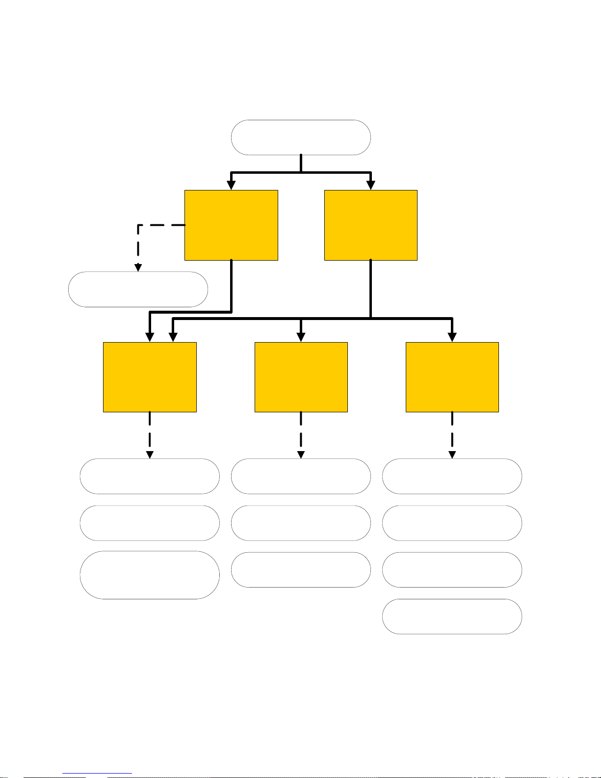
2.ASSEMBLY INSTRUCTION
3-2
BASE
ASSEMBLY
TLPC001
UNIT
3-5
BOTTOM
COVER
ASSEMBLY
3-4
TOP COVER
ASSEMBLY
3-3
ARM
ASSEMBLY
3-1
CAMERA
ASSEMBLY
U002
KEYPAD PCB
U001
MAIN PCB
E002
CAMERA HEAD ASSY
E001
ARM ASSEMBLY
B001
SPRING+BEARING
A005
FOOT, RUBBER
A004
LABEL, SPEC
A003
CAMERA HEAD
COVER KIT
A002
BOTTOM COVER
A001
TOP COVER ASSY
U003
IR RECEIVER
3
Cautions Before Servicing
Electronic parts are susceptible to static electricity and may easily be damaged, so
do not forget to take proper grounding treatment as required.
Many screws are used inside the unit. To prevent missing, dropping, etc. of the
screws, always use a magnetized screwdriver in servicing. Several kinds of screws
are used and some of them need special cautions. That is, take care of the tapping
screws securing molded parts and fine pitch screws used to secure metal parts. If
they are used improperly, the screw holes will be easily damaged and the parts can
not be fixed.
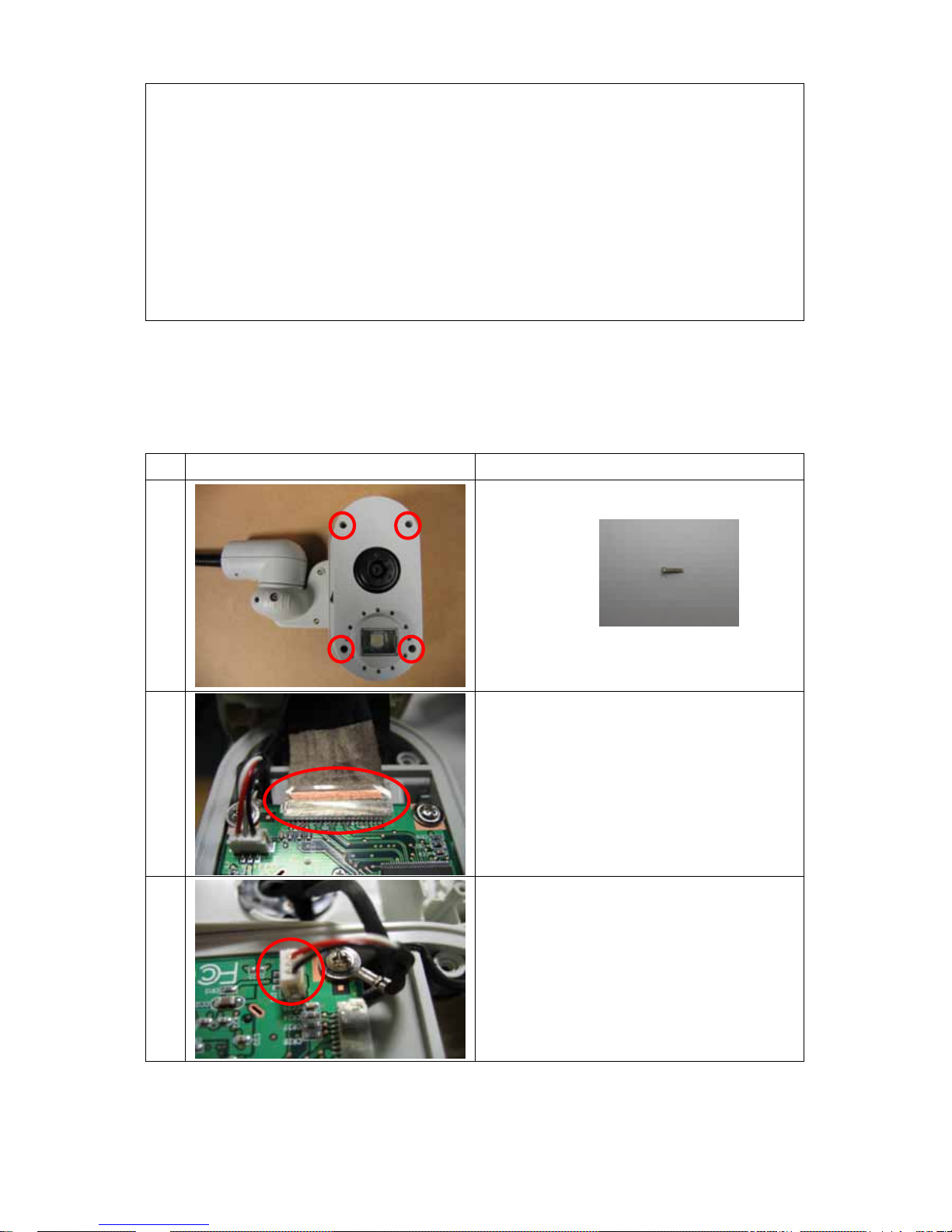
3.REPLACEMENT OF MECHANICAL PARTS
3-1 Camera Assembly
Step Figure Explanation
1 Remove four S-1 (force:1.8~2lb).
2 1.Tear off the sticker on the cable,
2.Remove the cable.
3 Remove the 3pin cable.
4
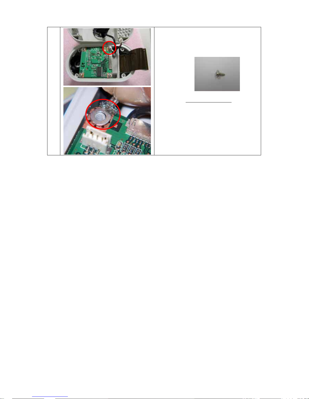
4 Remove the S-2 (force:2.8~3lb) that
connected with “CAMERA HEAD
ASSY”[23587758]
Note: Go to 3-3 Arm Assembly for the
further assembly instruction.
5

3-2 Base Assembly
Step Figure Explanation
1
Remove four “FOOT,
RUBBER”[23587753]
2 Remove five S-3 (force:2.8~3lb).
3 1.Tear off the sticker “LABEL,
SPEC”[23587754]
2.Remove two S-4 (force:4.8~5lb).
4 Remove the fixture metal.
6
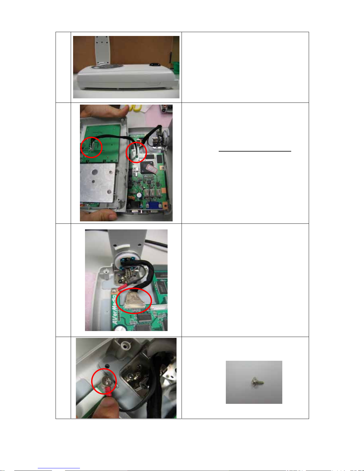
5 Open the top cover from the base.
6
Remove the cable which is connected with
top cover and the base.
Note: Go to 3-4 Top Cover Assembly
for
the further assembly instruction.
7
Tear off the sticker on the cable and
disconnect it.
Note: Be careful for the direction of
connector when connect the cable back
with mainboard
8 Remove the S-2 (force:2.8~3lb) which is
connected with arm assembly and base.
7

9 Remove two S-5 (force:4.8-5lb)
Note: Go to 3-3 Arm Assembly
and 3-5
Bottom Cover Assembly for the further
assembly instruction.
8

3-3 Arm Assembly
Step Figure Explanation
1 1.Remove three S-1 (force:1.8~2lb)
2.Remove one S-9 (force:4.8~5lb)
2 Remove one S-1 (force:1.8~2lb)
3 Remove two S-6 (force:2.8~3lb)
Note: The black rotation pad should be
assembled with the right position.
4 Take off the camera head - “CAMERA
HEAD COVER KIT”[23587753] and
remove the
“SPRING+BEARING”[23587756]
S-1
S-1
S-1
S-9
9

5 1.Remove two S-2 (force:2.8~3lb)
2.Take off the joint cover-“CAMERA HEAD
COVER KIT”[23587753]
10

3-4 Top Cover Assembly
Step Figure Explanation
1 1.Remove four S-2 (force:2.8~3lb)
2.Take off two metal plates
2 Remove the cable which is connected with
“IR RECEIVER”[23587761] and “KEY
PAD PCB”[23587760]
Note: Please put the cable into the track of
case when connect it back
3 1.Remove four S-1 (force:0.8~1lb)
2.Take off “KEY PAD PCB”[23587760]
4 1.Remove two S-7 (force:0.8~1lb)
2.Take off “KEY PAD PCB”[23587760]
11

3-5 Bottom Cover Assembly
Step Figure Explanation
1 Remove four S-8 (force:2.8~3lb)
2 1.Remove three S-2 (force:2.8~3lb)
2.Take off “MAIN PCB”[23587759]
3 1.Remove one S-2 (force:2.8~3lb)
2.Take off the bottom plate
4 Remove two metal plates
12
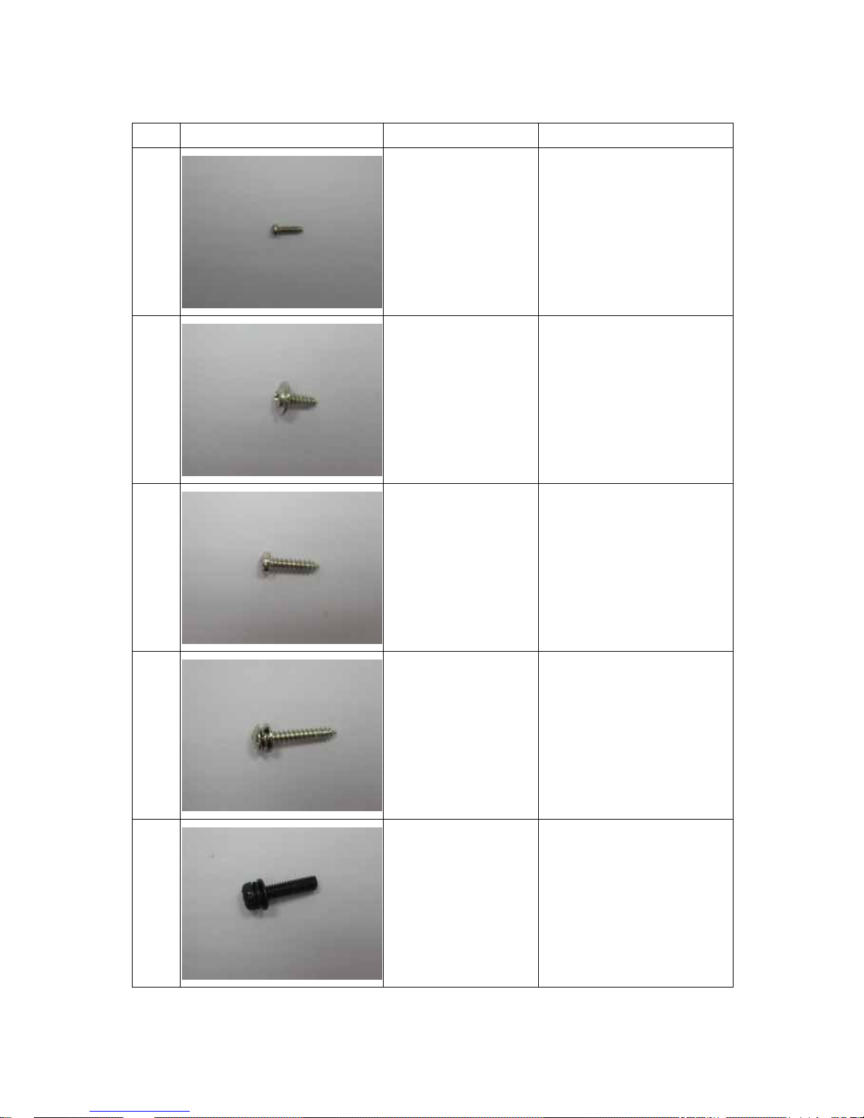
3-6 Screws
Type FORM SIZE Location
S-1 T2x7 Camera Assembly(4)
Arm Assembly(4)
Top Cover Assembly(4)
S-2 T2.6x8 Camera Assembly(1)
Base Assembly(1)
Arm Assembly(2)
Top Cover Assembly(4)
Bottom Cover Assembly(4)
S-3 T2.6x14 Base Assembly(5)
S-4 T2.6x15 Base Assembly(2)
S-5 M3x12 Base Assembly(2)
13

S-6 T2.6x8 Arm Assembly(2)
S-7 M2x4 Top Cover Assembly(2)
S-8 M4.75x7 Bottom Cover Assembly(4)
S-9 M3x7 Arm Assembly(1)
14

SECTION 2
SERVICING DIAGRAMS
1.TROUBLE SHOOTING
1-1.Debuging Function
BUTTON FUNCTION DESCRIPTION
“ZOOM –”+
“ ”
EDID checking
(ON/OFF)
To recognize Toshiba projector, if the display is
not admitted by TSB, the image will disappear
after 10 seconds.
“ZOOM –” +
“ ”
Test Pattern
(ON/OFF)
Run the Camera DSP test pattern
“ZOOM –“ +
“ ”
Debug Mode Enter the Debug mode (See the following
explanation)
“ZOOM –“ +
“ ”
Remote Control
(ON/OFF)
Enable the remote control function
NOTE:
1. Debug Mode:
SELECTION DESCRIPTION
MX88L284 System Register
Default Back to the factory setting
FPGA System Register
CMOS Sensor System Register
ISP Update FW ( See 3) I2C
EEPROM-Version Check FW version
MXIC-Block0 Test MXIC Pattern Pattern
MXIC-Restore Close the MXIC Pattern
Auto Test Test Test EEPROM in
2. Press two buttons at the same time and last for 3 seconds at least to active the
debugging function.
3. Press “INPUT” to close the menu of Debug mode.
15

1-2.Trouble Shooting
CAUSE CHECK POINT CHECK ITEM JUDGE
A. Power supply (NG)
=>Power supply is NG
(OK)
=>Check next step
Power is not on 1.Power supply is
connected well.
2.No light on
“ON/Standby” LED
B. Keypad PCB
connection with
+3.3V
(NG)
=>KEYPAD PCB or
Cable1 (2-1) is NG
(OK)
=>MAIN PCB is NG
Standby mode
couldn’t be
powered on
”ON/Standby” LED Color keeps on
orange
=>KEYPAD PCB or MAIN
PCB is NG
MAIN PCB display MXIC Pattern
(See1-1)
(NG)
=>MAIN PCB is NG
(OK)
=>Check next step
Display is
abnormal
Camera DSP
display
Test Pattern
(See1-1)
(NG)
=>CAMERA HEAD ASSY
or Cable1(2-1) is NG
(OK)
=>MAIN PCB is NG
Flicker Switch FLICKER SW
(50/60 Hz)
(OK)
=>Normal
(NG)
=>Check next step
MAIN PCB display MXIC Pattern
(See1-1)
(NG)
=>MAIN PCB is NG
(OK)
=>Check next step
Display with
waved line
Camera DSP
display
Test Pattern
(See1-1)
(NG)
=>CAMERA HEAD ASSY
or Cable1(2-1) is NG
(OK)
=>MAIN PCB is NG
16

Message
display is wrong
when turn on
1.The display is
magnified to 190%
2.The “190%”
appear position is
wrong
Check the FW
version (See 1-1)
=>Update the FW
(See 3)
LED on the
Camera is not
lighted
LED SW LED lamp =>CAMERA HEAD ASSY
is NG
17

2.CONNECTOR PIN ASSIGNMENT
2-1.U001 (MAIN PCB-J5)<->E002 (CAMERA PCB-CJ1):
It is included in E002: ARM ASSEMBLY
U001 DEFINITION E002 DEFINITION SIGNAL FORMAT
1 LIGHT LIGHT 20 (ON) +3.3V / (OFF) 0V
2 GND GND 19 0V
3 SSCL SCLK 18 0 V to +3.3V (Pulse)
4 SSDA SDATA 17 0 V to +3.3V (Pulse)
5 GND GND 16 0V
6 RAM TA- 15 200mV(Swing)
7 RAP TA+ 14 200mV(Swing)
8 GND GND 13 0V
9 RBM TB- 12 200mV(Swing)
10 RBP TB+ 11 200mV(Swing)
11 GND GND 10 0V
12 RCLKM TCLK- 9 200mV(Swing)
13 RCLKP TCLK+ 8 200mV(Swing)
14 GND GND 7 0V
15 5V 5V 6 +5V
16 5V 5V 5 +5V
17 5V 5V 4 +5V
18 3V7 3V7 3 +3.7V
19 3V7 3V7 2 +3.7V
20 3V7 3V7 1 +3.7V
2-2.U001 (MAIN PCB-J3)<->U002 (KEYPAD PCB-KJ2)
U001 DEFINITION U002 DEFINITION SIGNAL FORMAT
1 REMOTE REMOTE 9 0 V to +3.3V (Pulse)
2 KEY-DO KEY-DO 8 0 V to +3.3V (Pulse)
3 KEY-CLK KEY-CLK 7 0 V to +3.3V (Pulse)
4 KEY-LED KEY-LED 6 0 V to +3.3V (Pulse)
5 KEY-DI KEY-DI 5 0 V to +3.3V (Pulse)
6 3V3 3V3 4 +3.3V
7 3V3 3V3 3 +3.3V
18

8 GND GND 2 0V
9 GND GND 1 0V
3.U002 (KEY PAD PCB-KJ1)<->U003 (IR RECEIVER-RJ1)
U001 DEFINITION U002 DEFINITION SIGNAL FORMAT
1 3V3 POWER 5 +3.3V
2 GND GND 4 0 V
3 IRA IR1 3 0 V to +3.3V (Pulse)
4 IRB IR2 2 0 V to +3.3V (Pulse)
5 IRC IR3 1 0 V to +3.3V (Pulse)
19

3.BLOCK DIADRAM
U001:
MAIN PCB
U002:
KEYPAD PCB
U003:
IR RECEIVER
E002:
CAMERA HEAD
ASSY
RGB IN:
TO COMPUTER
POWER JACK:
+15V IN
RGB OUT:
TO PROJECTOR
FLICKER SW:
50Hz/60Hz
CABLE3:
5PIN(2-3)
CABLE1(E001):
ARM ASSEMBLY(2-1)
CABLE2:
9PIN(2-2)
20

4.CIRCUIT DIAGRAM
4-1.U001:MAIN PCB
4-2.E002: CAMERA HEAD ASSY
21

4-3. P0D1_ISP module
22

SECTION 3
PART LIST
NOTICE
The part number must be used when ordering parts in order to assist in processing, be sure
to include the model number and description.
Parts marked # are of chip type and mounted on original PC boards.
How ever, when they are placed for servicing works, use discrete parts listed on the parts list.
1.PACKING ASSEMBLY
1-1 Carton Assembly
Y005: CARTON BOX
Y006: INSERT
SOFT CASE ASSEMBLY
Y006: INSERT
23
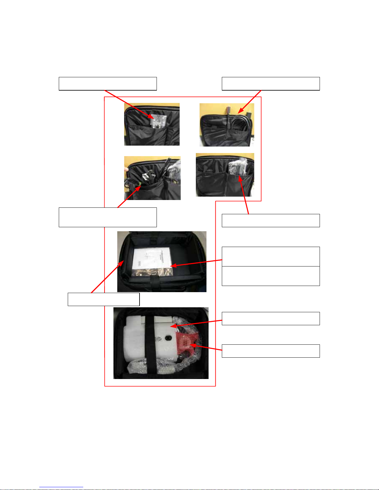
1-2 Soft Case Assembly
Y002: USERS MANUALHARD COPY
Y008-Y0012: POWER
CARD
Y013: RGB CABLE
Y007: AC ADAPTER
Y004: REMOTE CONTROL
Y003: USERS MANUAL-CD
Y014: LED HOOD
TLPC001 UNIT
Y001: SOFT CASE
24
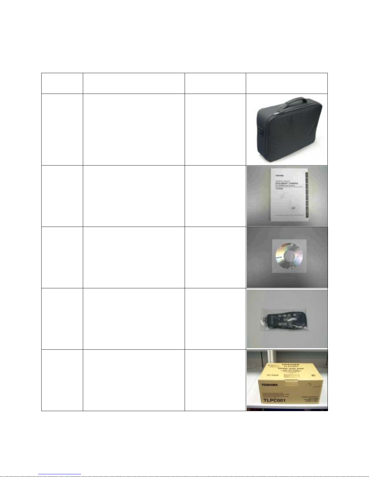
2.SPARE PARTS LIST
2-1.Accessories
LOCATION
NO
DESCRIPTION PARTS NO FIGURE
Y001
SOFT CASE
23587762
Y002
USERS MANUAL-HARD COPY
23587763
Y003
USERS MANUAL-CD
23587764
Y004
REMOTE CONTROL
23587765
Y005
CARTON BOX
23587766
25

Y006
INSERT
23587767
Y007
AC ADAPTER
23587768
Y008
POWER CORD-EU
23587769
Y009
POWER CORD-JP
23587770
Y010
POWER CORD-US
23587771
Y011
POWER CORD-CHINA
23587772
26

Y012
POWER CORD-UK
23587773
Y013
RGB CABLE
23587774
Y014
LED HOOD
23587775
27

2-2.Main Unit Parts
LOCATION
NO
DESCRIPTION PARTS NO FIGURE
A001
TOP COVER ASSY
23587751
A002
BOTTOM COVER
23587752
A003
CAMERA HEAD COVER KIT
23587753
28
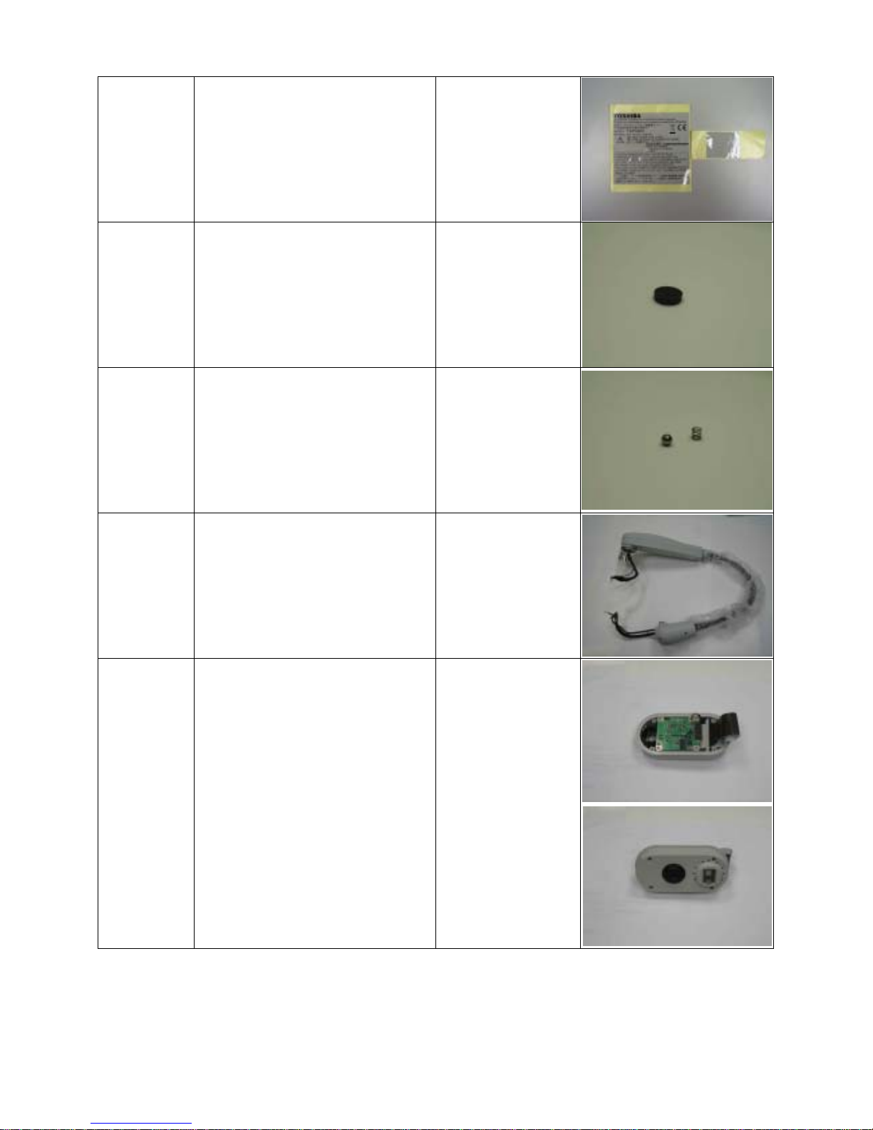
A004
LABEL,SPEC
23587754
A005
FOOT,RUBBER
23587755
B001
SPRING+BEARING
23587756
E001
ARM ASSEMBL Y
23587757
E002
CAMERA HEAD ASSY
23587758
29

U001
MAIN PCB
23587759
U002
KEY PAD PCB
23587760
U003
IR RECEIVER
23587761
30

2-3 Label
A004-1: LABEL, SPEC A004-2: LABEL, SPEC
31

TOS
1--1, SHIBAURA 1-- CHOME, MINATO -- KU, TOKYO 105 -- 8001, JAPAN
H
IBA CORPORATION
 Loading...