

Toshiba TLP-250, TLP-250C, TLP-251, TLP-251C, TLP-550 Service Manual
...
FILE NO. 330-200103
SUPPLEMENT
SERVICE MANUAL
3LCD DATA PROJECTOR
TLP-250/251/250C/251C
TLP-550/551/550C/551C
PART REPLACEMENT AND
N
800
Y
E
N
OUSING
S
L
N
Y
D
ADJUSTMENT PROCEDURES
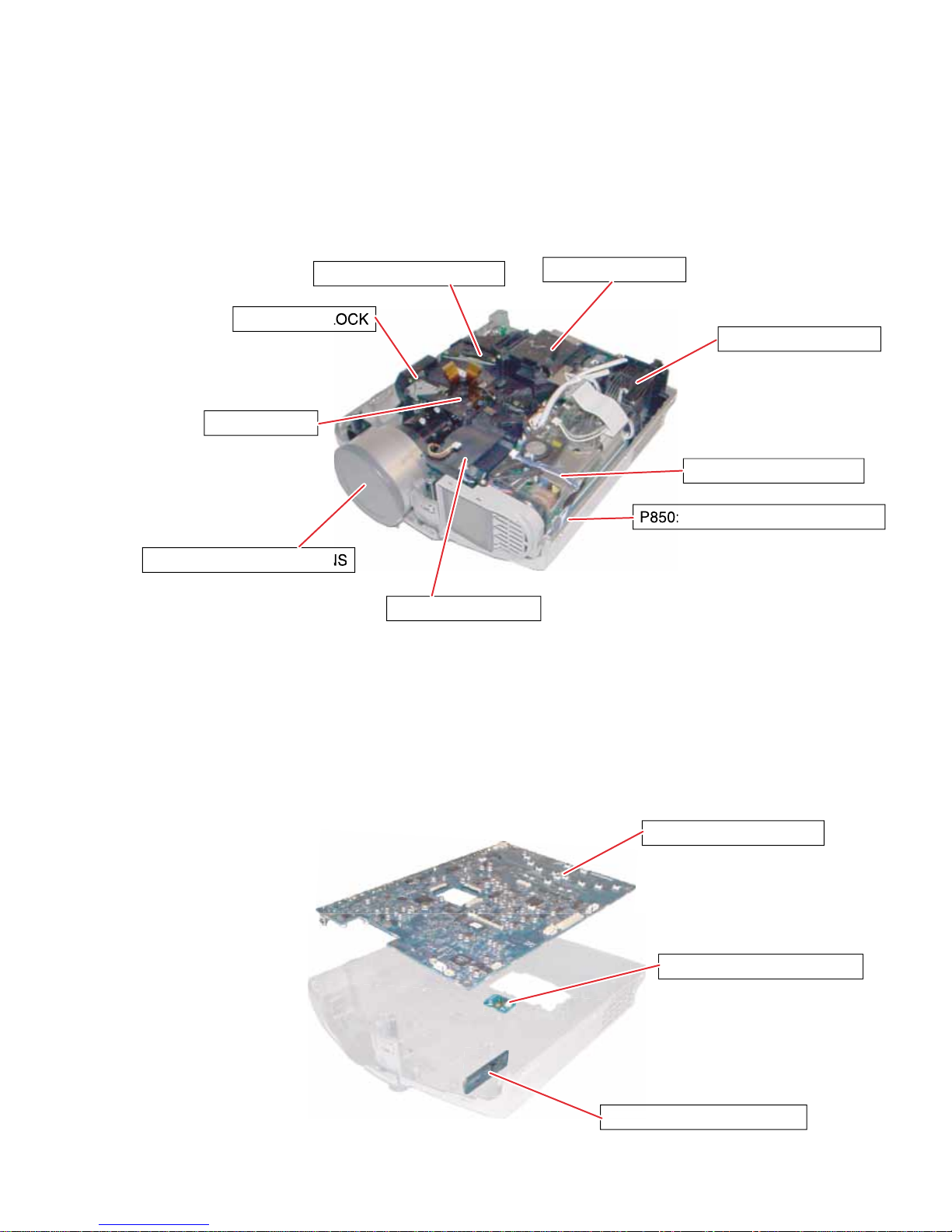
1. LOCATION OF MAIN PARTS
SECTION 1
PEAKER B
LCD BLOCK
E201A: PROJECTION LE
E200: OPTICAL ENGIN
Z100: INTAKE FA
LAMP H
Z101: EXHAUST FA
P
: POWER SUPPL
BALLAST POWER SUPPL
2. LOCATION OF PC BOARD
1: MAIN PC BOAR
U003: SWITCH PC BOARD
1-1
CAUTIONS BEFORE SERVICING
Electronic parts are susceptible to static electricity and may easily be damaged, so do not forget to take
proper grounding treatment as required.
Many screws are used inside the unit. To prevent missing, dropping, etc. of the screws, always use a
magnetized screwdriver in servicing. Several kinds of screws are used and some of them need special
cautions. That is, take care of the tapping screws securing molded parts and fine pitch screws used to
secure metal parts. If they are used improperly, the screw holes will be easily damaged and the parts can
not be fixed.
3. REPLACEMENT OF MECHANICAL PARTS
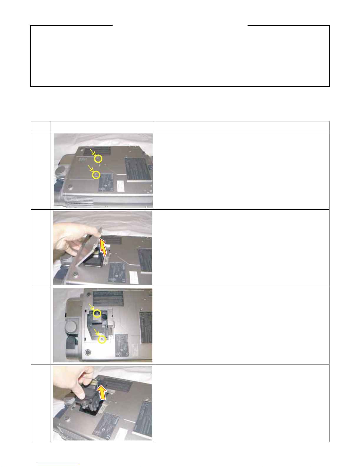
3-1. Lamp Assembly
Step Figure
1
2
Explanation
Loosen 2 screws (M3 x 8).
These screws are retained with split washers.
Remove the lamp cover.
3
4
Loosen 2 screws that secure the lamp module (M3 x 8).
These screws are retained with split washers.
Lift the lamp module and slide out from the projector.
1-2
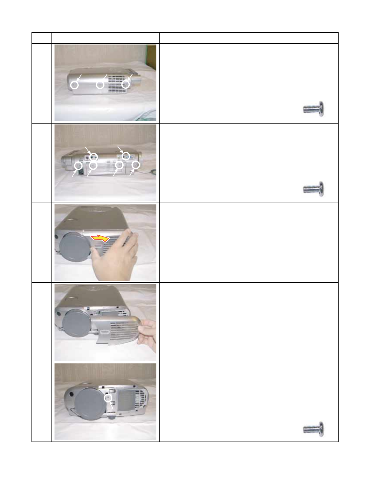
3-2. T op Cover
Step Figure Explanation
[Left Side]
Remove 3 screws (M3 x 6).
1
[Right Side]
Remove 6 screws (M3 x 6).
2
Screw : type [M-1]
Screw : type [M-1]
3
4
[Front]
Slide front cover to the right.
Remove front cover.
Remove 1 screw (M3 x 6).
5
Screw : type [M-1]
1-3
3-2. Top Cover (Continued)
Step Figure Explanation
[Rear]
Remove 1 screws (M2 x 6).
6
Top cover can be removed by lifting left edge.
7
Screw : type [M-1]
1-4
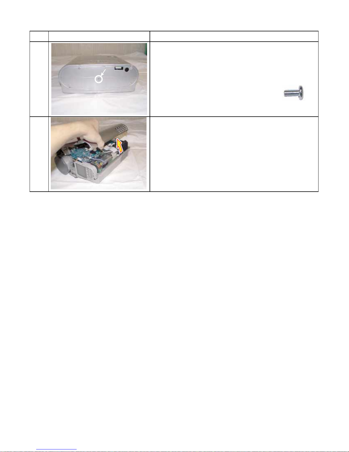
3-3. Main PC Board
Step Figure Explanation
Remove lens shift dial.
1
Remove all cables and connectors.
2
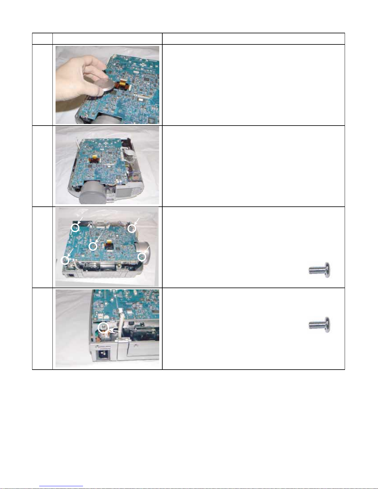
3
4
Remove 5 screws (M3 x 6).
Screw : type [M-1]
Remove 1 screws (M3 x 6).
Screw : type [M-1]
[Note]
The screw here is also fixing the grand wire.
1-5
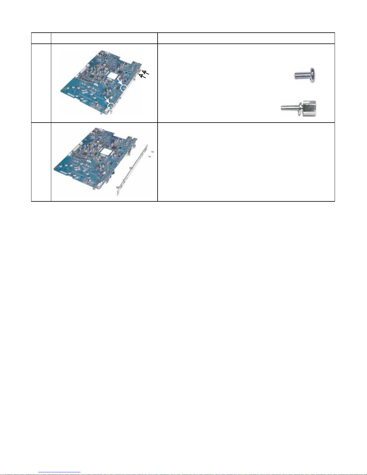
3-3. Main PC Board (Continued)
y
]
Step Figure Explanation
Remove 2 screws (M3 x 6).
Screw : type [M-1]
5
6
Remove 2 screws (M3 x 8).
Remove metal plate.
Screw : t
pe [M-10
1-6
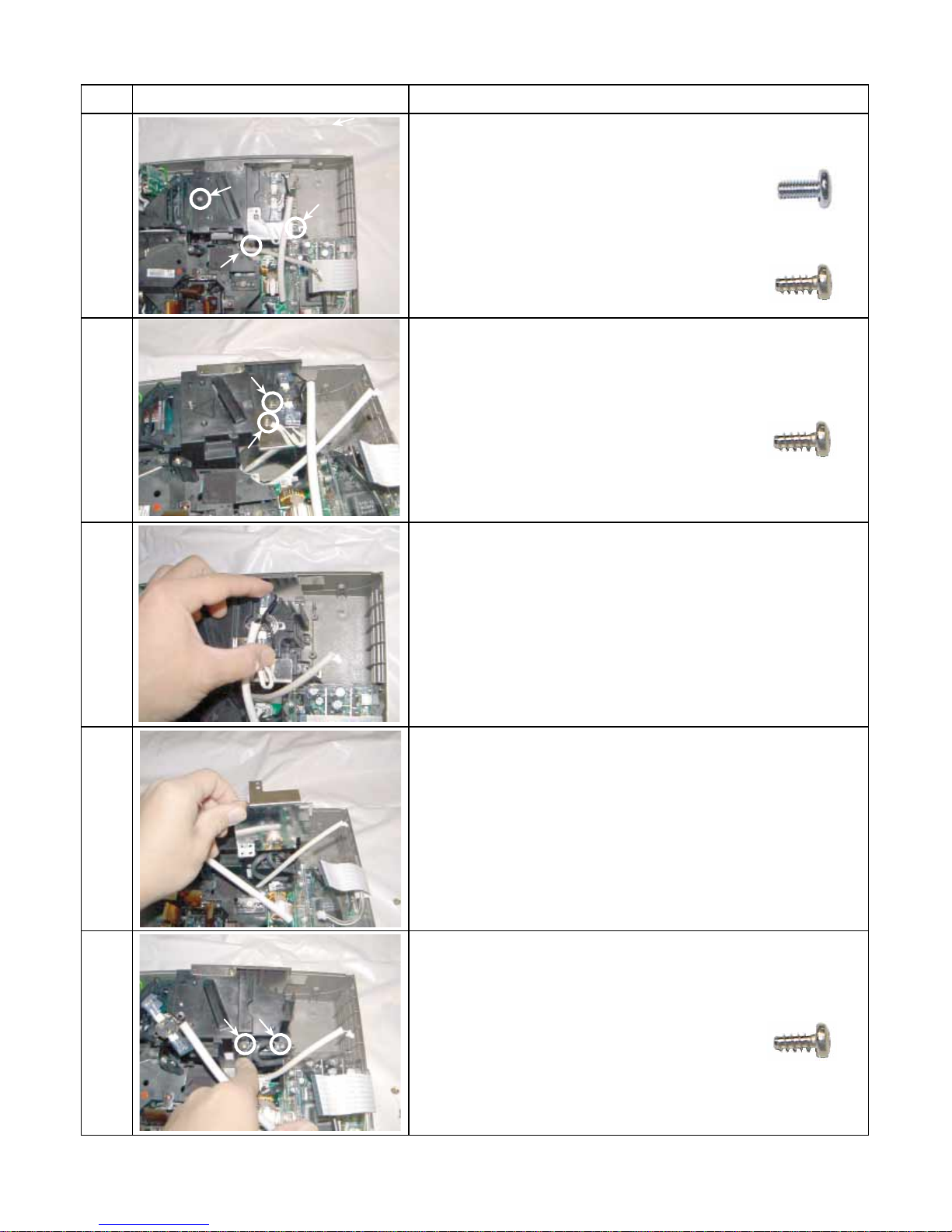
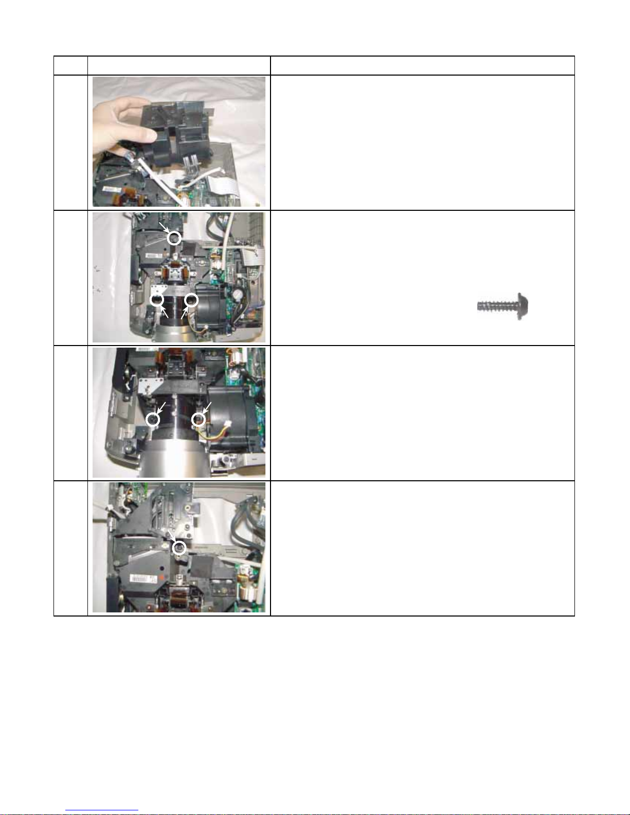
3-4. Optical Engine
Step Figure Explanation
1
2
Remove 1 screw (M3 x 6).......A
Screw : type [M-1]
A
B
Remove 2 screws (3 x 8)......B
Screw : type [M-2]
B
Remove 2 screws (3 x 8)
Screw : type [M-2]
Remove Thermal switch.
3
4
5
Remove metal plate.
Remove 2 screws (3 x 8)
Screw : type [M-2]
1-7
3-4. Optical Engine (Continued)
Step Figure Explanation
Remove lamp housing.
6
b
Remove 3 screws (M3 x 15).
7
7a
7b
Screw : type [M-4]
a
1-8
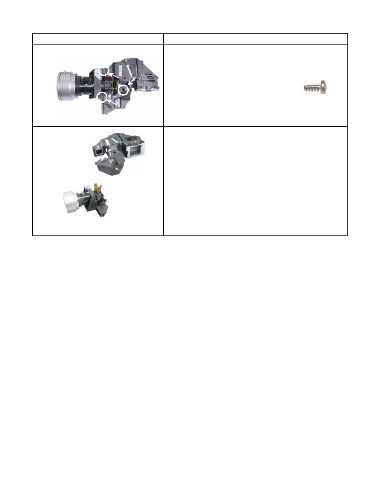
3-4. Optical Engine (Continued)
Step Figure Explanation
Remove 3 screws (M3 x 8) .
8
Separate the main frame and sub frame from the engine
block.
9
Screw : type [M-2]
Main frame
1-9
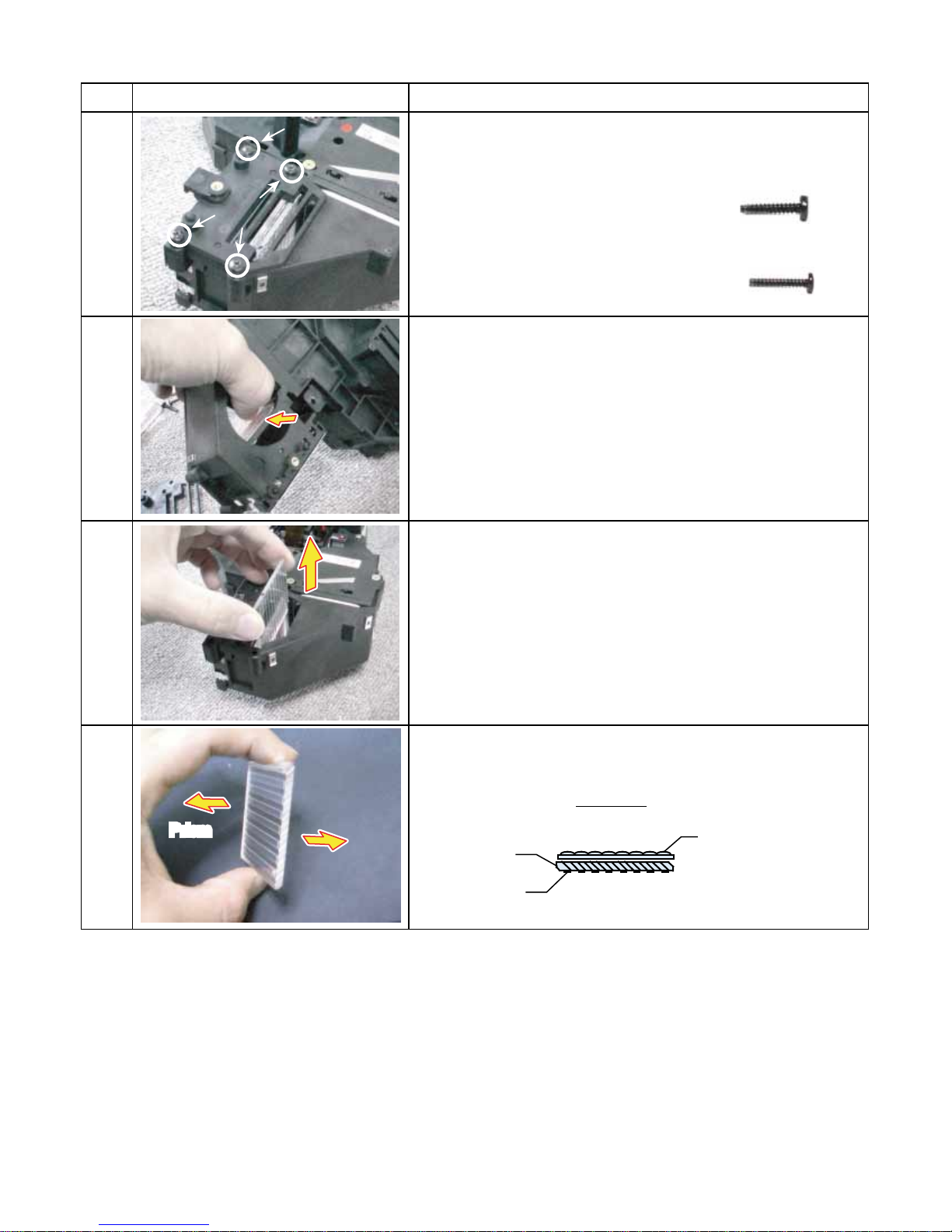
3-5. MULTI-PBS (Polarizing Beam Splitter)
y
]
Lamp
Step Figure Explanation
B
Remove 3 screws (M3 x 15) ....A
Screw : type [M-8]
1
2
3
A
Remove 1 screws (M2.5 x 15) ....B
Screw : t
Press the Multi-PBS up from cooling space.
Remove the Multi-PBS.
pe [M-9
4
Prism
Lamp
Lamp
[Note]
Make sure the direction of the PBS when you install.
TOP VIEW
PBS
Rotation Film
Lamp SIDE
Prism SIDE
Multi Lens
1-10
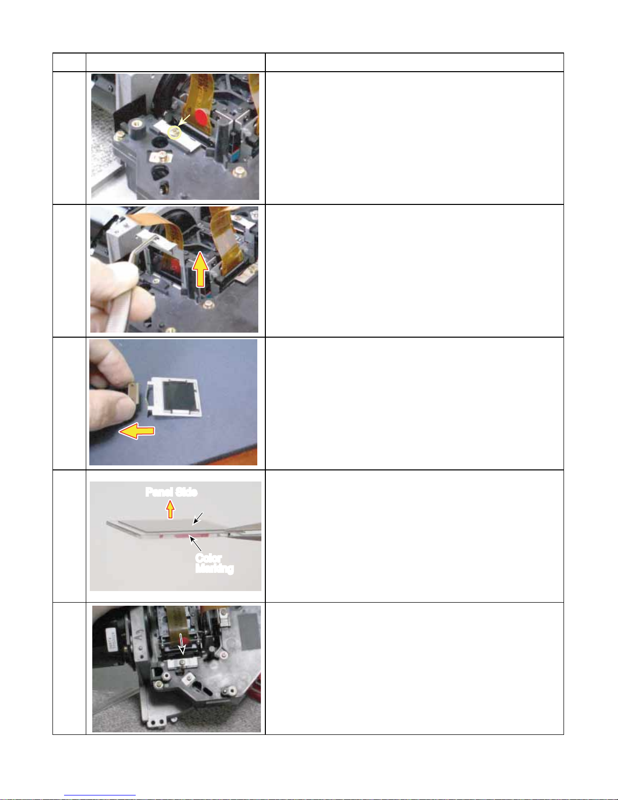
3-6. Polarized Plate
polarizer film
Step Figure Explanation
Remve the one screw.
1
Remove the stopper.
2
3
4
Panel Side
polarizer film
polarizer film
Color
Marking
Remove the holder and polarized plate.
[Note]
The film side must be faced to the LCD panel when installing
and the color must be related with the color of LCD panel.
Tighten a screw in the position where 100% black image
screen gets the darkest.
5
1-11
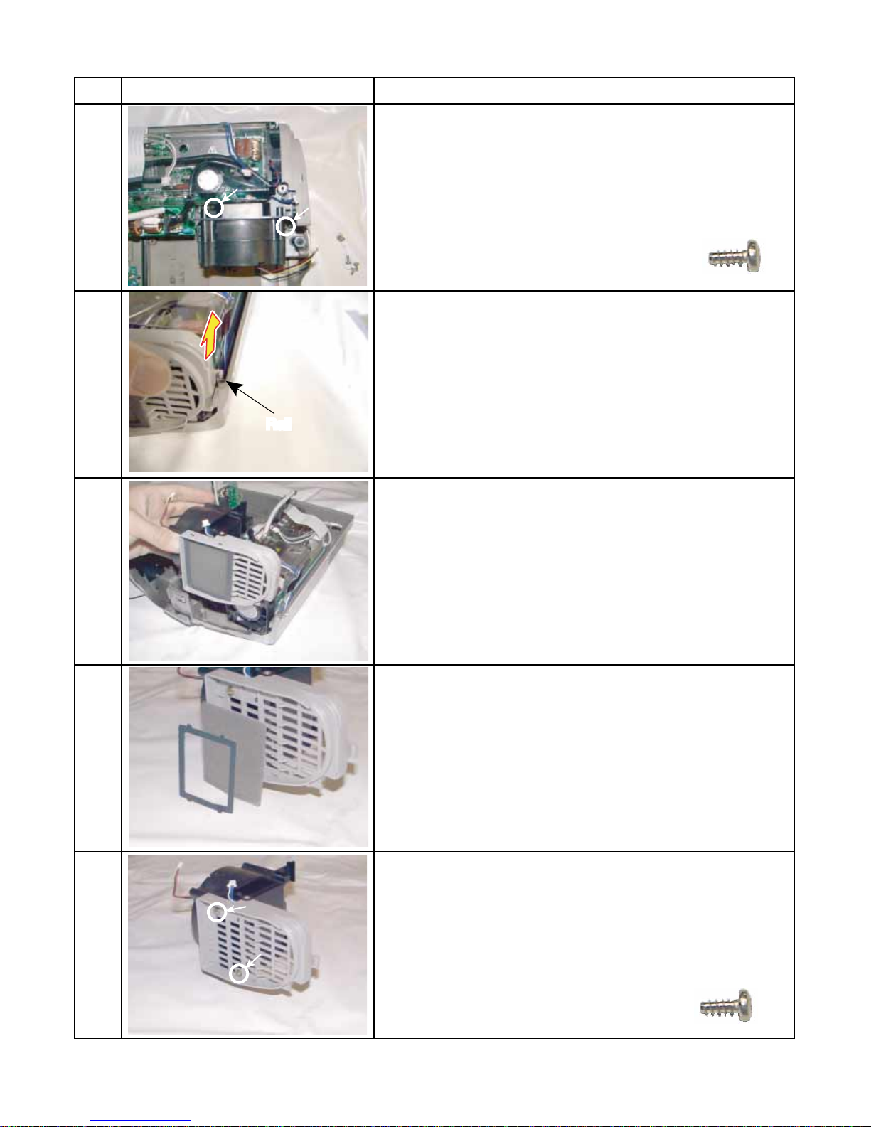
3-7. Intake Fan
Step Figure Explanation
Remove 2 screw (3 x 8).
1
Remove intake fan block from the bottom cabinet.( It pulls
up along with a rail. )
2
Rail
Screw : type [M-2]
3
4
Remove filter block from the bottom cabinet.
The filter is split like this.
Remove 2 screws (3 x 8).
5
Screw : type [M-2]
1-12

3-7. Intake Fan (Continued)
Step Figure Explanation
Remove 2 screw (3 x 47).
6
The Intake fan block is split like this.
7
Screw : type [M-5]
1-13
 Loading...