

TOSHIBA TLP130 Technical data
现货库存、技术资料、百科信息、热点资讯,精彩尽在鼎好!
TOSHIBA Photocoupler GaAs Ired & Photo−Transistor
TLP130
TLP130
Programmable Controllers
AC / DC−Input Module
Telecommunication
The TOSHIBA mini flat coupler TLP130 is a small outline coupler,
suitable for surface mount assembly.
TLP130 consists of a photo transistor, optically coupled to two gallium
arsenide infrared emitting diode connected inverse parallel, and operate
directly by AC input current.
· Collector−emitter voltage: 80V(min.)
· Current transfer ratio: 50%(min.)
Rank GB: 100%(min.)
· Isolation voltage: 3750Vrms(min.)
· UL recognized: UL1577, file no.E67349
· Current transfer ratio
Classification
Standard 50 600 Blank, Y, GR, GB
Rank GB 100 600 GB,GR
Current Transfer Ratio
IF = 5mA, VCE = 5V, Ta = 25°C
Min. Max.
Marking Of
Classification
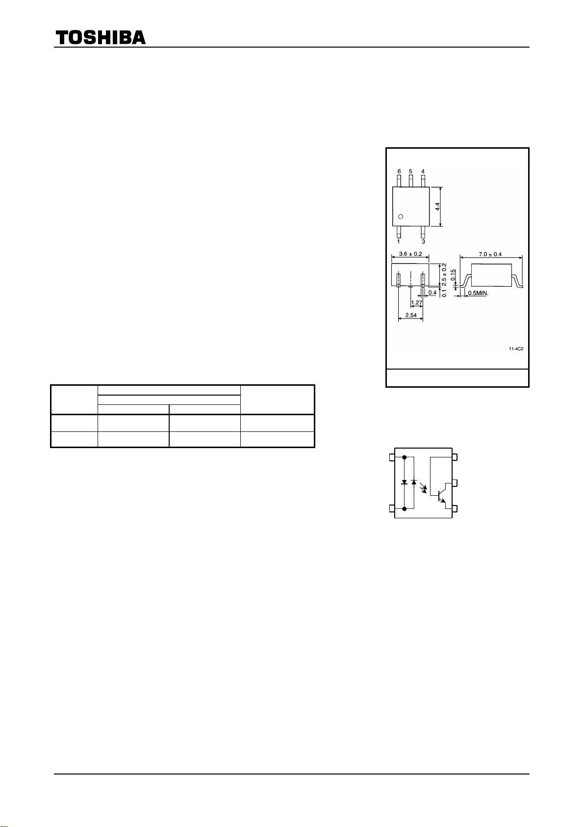
Unit in mm
TOSHIBA 11−4C2
Weight: 0.09 g
(Note) Application type name for certification test,
please use standard puroduct type name, i.e.
TLP130(GB): TLP130
1
3
1 : Anode, Cathode
3 : Cathode, Anode
4 : Emitter
5 : Collector
6 : Base
6
5
4
1
2002-09-25
TLP130
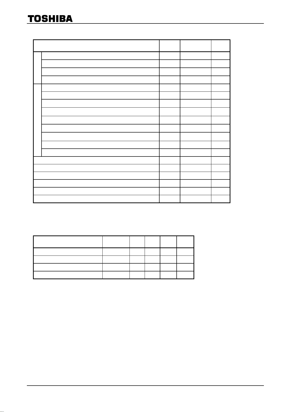
Maximum Ratings
(Ta = 25°C)
Characteristic Symbol Rating Unit
Forward current I
F(RMS)
50 mA
Forward current derating (Ta≥53°C) ∆IF / °C -0.7 mA / °C
LED
Peak forward current (100µs pulse,100pps) I
FP
1 A
Junction temperature Tj 125 °C
Collector-emitter voltage V
Collector-base voltage V
Emitter-collector voltage V
Emitter-base voltage V
Collector current I
Detector
Peak collector current (10ms pulse,100pps) I
CEO
CBO
ECO
EBO
C
CP
80 V
80 V
7 V
7 V
50 mA
100 mA
Power dissipation PC 150 mW
Power dissipation derating (Ta≥25°C) ∆PC / °C -1.5 mW / °C
Junction temperature T
Storage temperature range T
Operating temperature range T
Lead soldering temperature (10s) T
stg
opr
sol
j
125 °C
-55~125 °C
-55~100 °C
260 °C
Total package power dissipation PT 200 mW
Total package power dissipation derating (Ta≥25°C) ∆PT / °C -2.0 mW / °C
Isolation voltage (AC, 1min., RH ≤ 60%) (Note 1) BV
S
3750 V r m s
(Note 1) Device considered a two terminal device: Pins 1 and 3 shorted together and pins 4, 5 and 6 shorted
together.
Recommended Operating Conditions
Characteristic Symbol Min. Typ. Max. Unit
Supply voltage V
Forward current I
Collector current I
Operating temperature T
CC
F(RMS)
C
opr
― 5 48 V
― 16 25 mA
― 1 10 mA
-25 ― 85 °C
2
2002-09-25
TLP130
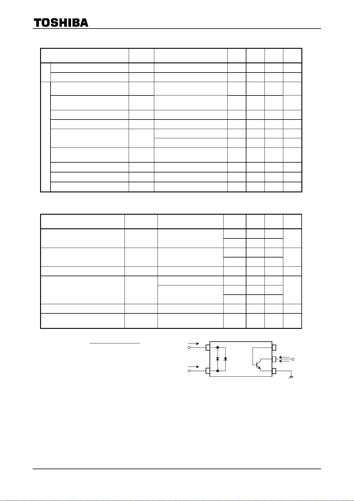
Individual Electrical Characteristics
Characteristic Symbol Test Condition Min. Typ. Max. Unit
Forward voltage V
LED
Capacitance C
Collector-emitter
breakdown voltage
Emitter-collector
breakdown voltage
Collector-base breakdown voltage
Emitter-base breakdown voltage
Collector dark current I
F
T
V
(BR)CEOIC
V
(BR)ECOIE
V
(BR)CBOIC
V
(BR)EBOIE
CEO
Detector
Collector dark current I
Collector dark current I
CER
VCB = 10V ― 0.1 ― nA
CBO
DC forward current gain hFE VCE = 5V, IC = 0.5mA ― 400 ― ―
Capacitance collector to emitter
C
CE
Coupled Electrical Characteristics
(Ta = 25°C)
IF = ±10mA 1.0 1.15 1.3 V
V = 0, f = 1MHz ― 60 ― pF
= 0.5mA 80 ― ― V
= 0.1mA 7 ― ― V
= 0.1mA 80 ― ― V
= 0.1mA 7 ― ― V
VCE = 48V ― 10 100 nA
V
= 48V, Ta = 85°C ― 2 50 µA
CE
= 48V, Ta = 85°C
V
R
CE
= 1MΩ
BE
― 0.5 10 µA
V = 0 , f = 1MHz ― 10 ― pF
(Ta = 25°C)
Characteristic Symbol Test Condition Min. Typ. Max. Unit
Current transfer ratio IC / I
Saturated CTR IC / I
F
F(sat)
IF = ±5mA, VCE = 5V
IF = ±1mA, VCE = 0.4V
Rank GB
Rank GB
50 ― 600
100 ― 600
― 60 ―
30 ― ―
Base photo-current IPB IF = ±5mA, VCB = 5V ― 10 ― µA
IC = 2.4mA, IF = ±8mA ― ― 0.4
Collector-emitter
saturation voltage
Off-state collector current I
CTR symmetry I
V
CE(sat)
C(off)
C(ratio)
IC = 0.2mA, IF = ±1mA
Rank GB
― 0.2 ―
― ― 0.4
IF = ±0.7mA, VCE = 48V ― 1 10 µA
= -5mA) / IC(IF = 5mA)
I
C(IF
(Note 2)
0.33 ― 3 ―
(Note 2) I
C(ratio) =
V
IF(IC2I
I
F2,
V
I
F1,
F(IC1
CE
CE
V)
5
==
V)
5
==
I
F1
I
C1
IC2
I
F2
%
%
V
V
CE
3
2002-09-25
 Loading...