

TOSHIBA TLP126 Technical data
查询TLP126供应商
TOSHIBA Photocoupler GaAs Ired & Photo−Transistor
TLP126
TLP126
Programmable Controllers
AC / DC−Input Module
Telecommunication
The TOSHIBA mini flat coupler TLP126 is a small outline coupler,
suitable for surface mount assembly.
TLP126 consists of a photo transistor, optically coupled to a gallium
arsenide infrared emitting diode connected inverse parallel, and provides
high CTR at low AC input current.
· Collector−emitter voltage: 80 V (min.)
· Current transfer ratio: 100% (min.)
· Isolation voltage: 3750Vrms (min.)
· UL recognized: UL1577, file No. E67349
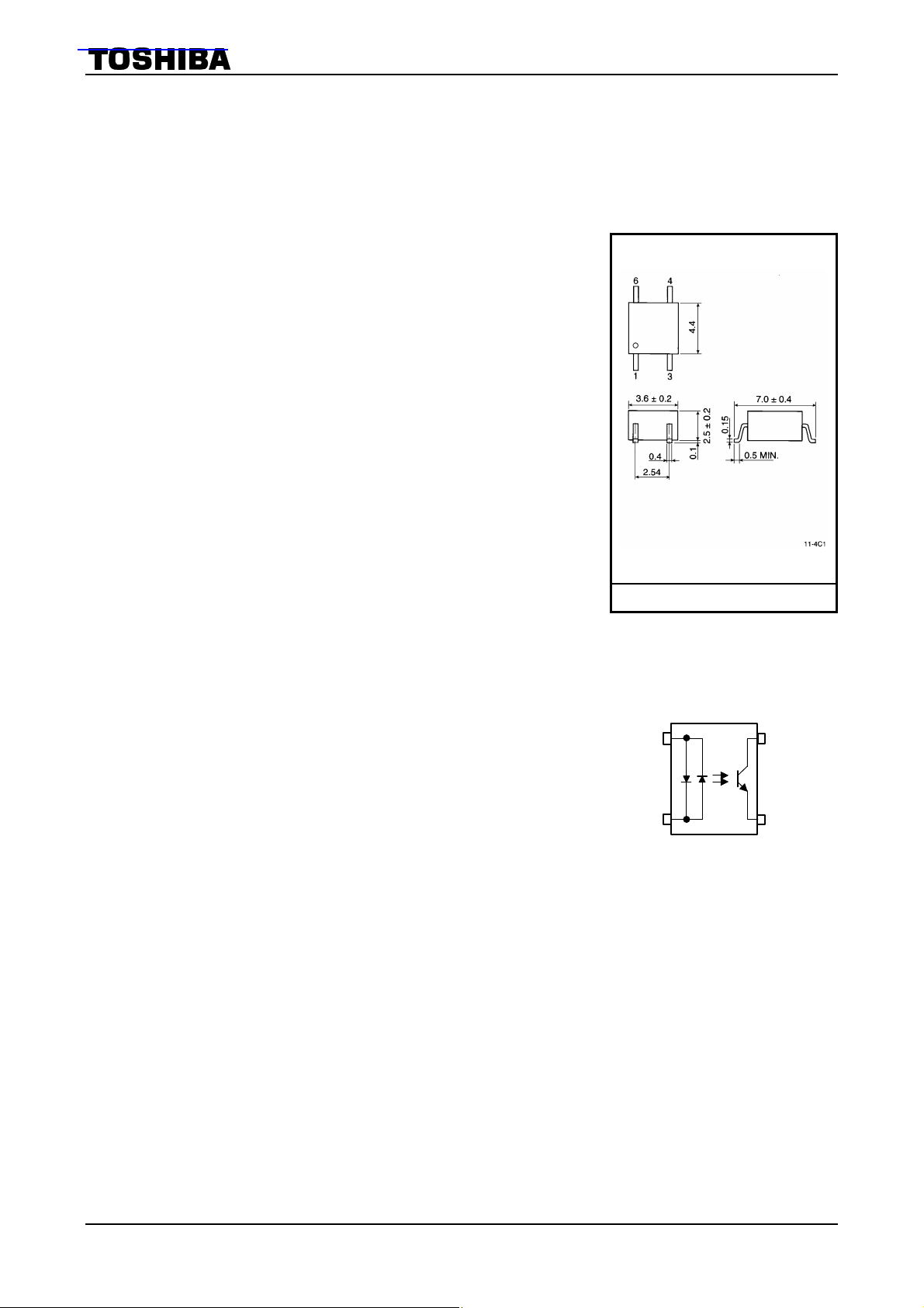
Unit in mm
TOSHIBA 11−4C1
Weight: 0.09 g
Pin Configurations
view)
1
3
1 : Anode, Cathode
3 : Cathode, Anode
4 : Emitter
6 : Collector
6
4
(top
1
2002-09-25
TLP126
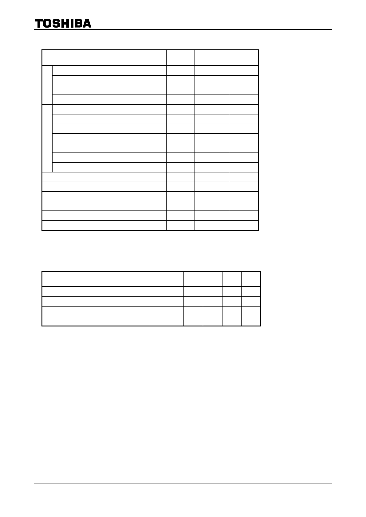
Maximum Ratings
Forward current I
Forward current derating (Ta≥ 53°C) ∆ ∆IF / °C -0.7 mA / °C
LED
Peak forward current(100µs pulse,100pps) IFP 1 A
Junction temperature Tj 125 °C
Collector-emitter voltage V
Emitter-collector voltage V
Collector current IC 50 mA
Peak collector current(10ms pulse,100pps) ICP 100 mA
Detector
Power dissipation PC 150 mW
Power dissipation derating (Ta ≥ 25°C) ∆PC / °C -1.5 mW / °C
Junction temperature Tj 125 °C
Storage temperature range T
Operating temperature range T
Lead soldering temperature(10 sec.) T
Total package power dissipation PT 200 mW
Total package power dissipation derating (Ta≥25°C) ∆PT / °C -2.0 mW / °C
Isolation voltage (AC, 1min., RH ≤ 60%) (Note 1) BVS 3750 Vrms
(Ta = 25°C)
Characteristic Symbol Rating Unit
50 mA
F(RMS)
80 V
CEO
7 V
ECO
-55~125 °C
stg
-55~100 °C
opr
260 °C
sold
(Note 1) Device considered a two terminal device: Pins1, and 3 shorted together and 4
and 6 shorted together.
Recommended Operating Conditions
Characteristic Symbol Min. Typ. Max. Unit
Supply voltage VCC ― 5 48 V
Forward current I
Collector current IC ― 1 10 mA
Operating temperature T
― 1.6 20 mA
F(RMS)
-25 ― 75 °C
opr
2
2002-09-25
TLP126
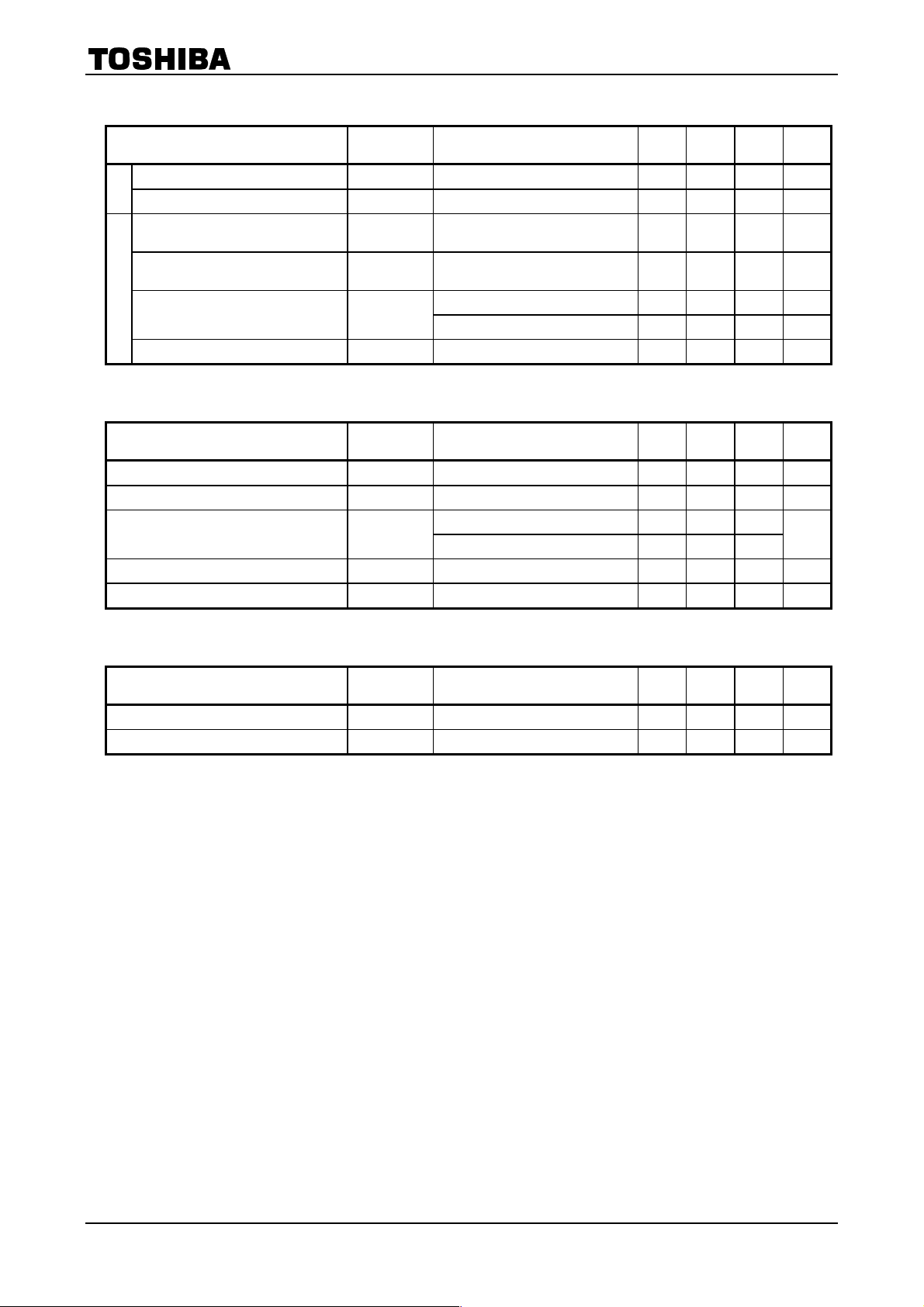
Individual Electrical Characteristics
Characteristic Symbol Test Condition Min. Typ. Max. Unit
Forward voltage VF IF = ±10 mA 1.0 1.15 1.3 V
LED
Capacitance CT V = 0, f = 1 MHz
Collector-emitter
breakdown voltage
Emitter-collector
breakdown voltage
Detector
Collector dark current I
Capacitance collector to emitter CCE V = 0, f = 1 MHz
Coupled Electrical Characteristics
Characteristic Symbol Test Condition MIn. Typ. Max. Unit
Current transfer ratio IC / I
Low input CTR IC / I
Collector-emitter
saturation voltage
Off-state collector current I
CTR symmetry I
Coupled Electrical Characteristics
V
(BR) CEOIC
V
(BR) ECOIE
CEO
(Ta = 25°C)
F (low)
V
CE (sat)
C(off)
C (ratio) IC
(Ta = ----25~75°C)
(Ta = 25°C)
= 0.5 mA 80
= 0.1 mA 7
VCE = 48 V
V
CE
= 48 V, Ta = 85°C
―
―
―
―
60 ― pF
― ―
― ―
10 100 nA
2 50 µA
12 ― pF
V
V
IF = ±1 mA, VCE = 0.5 V 100 ― 1200 %
F
IF = ±0.5 mA, VCE = 1.5 V 50 ― ― %
IC = 0.5 mA, IF = ±1 mA ― ― 0.4
IC = 1 mA, IF = ±1 mA ― 0.2 ―
VF = ± 0.7V, VCE = 48 V ― 1 10 µA
(IF = -1mA) / IC (IF = 1mA) 0.3 ― 3 —
V
Characteristic Symbol Test Condition MIn. Typ. Max. Unit
Current transfer ratio IC / I
Low input CTR IC / I
F
F (low)
IF = 1 mA, VCE = 0.5 V 50 ― ― %
IF = 0.5 mA, VCE = 1.5 V ― 50 ― %
3
2002-09-25
 Loading...