

Toshiba TLP115 Datasheet
TOSHIBA Photocoupler GaAℓAs IRed & Photo−IC
TLP115
High Speed, Long Distance Isolated Line Receiver
Microprocessor System Interfaces
Digital Isolation For A / D, D / A Conversion
Computer−Peripheral Interfaces
Ground Loop Elimination
The TOSHIBA mini flat coupler TLP115 is small outline coupler, suitable
for surface mount assembly.
TLP115 consists of a GaAℓAs light emitting diode, optically coupled to an
integrated high gain, high speed shielded photo detector whose output is
an open collector schottky clamped transistor.
The shield, which shunts capacitively coupled common noise to ground,
provides a guaranteed transient immunity specification of 1000V / µs.
· Input current thresholds: I
· Switching speed: 10MBd (typ.)
· Common mode transient immunity: ±1000V / µs (min.)
· Guaranteed performance over temp.: 0~70°C
· Isolation voltage: 2500Vrms (min.)
· UL recognized: UL1577, file no. E67349
Schematic
=10mA (max.)
F
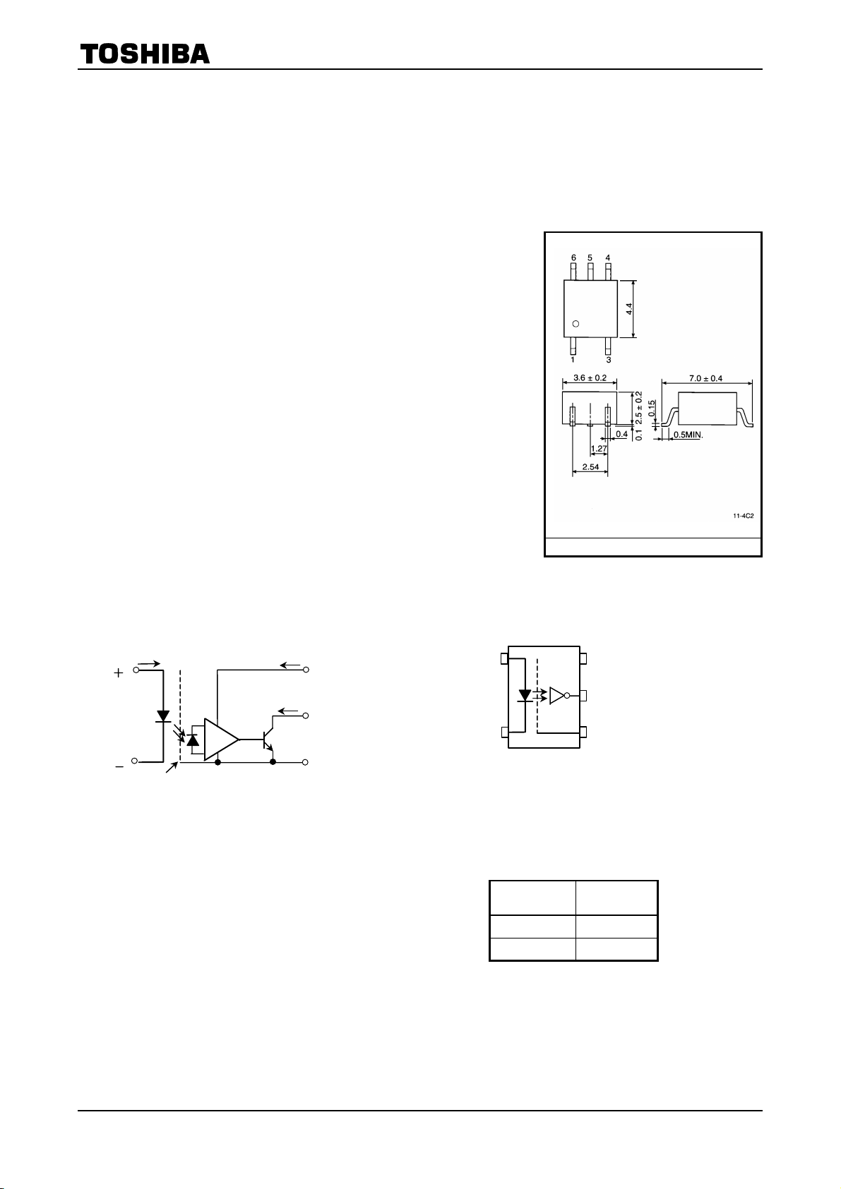
TOSHIBA 11−4C2
Weight: 0.09 g
Pin Configuration
(top view)
TLP115
Unit in mm
IF
1
V
F
3
Shield
Note. A 0.1µF bypass capacitor must be connected
between pins 4 and 6.
ICC
IO
6
5
4
VCC
V
O
GND
1
3
1 : Anode
3 : Cathode
4 : GND
5 : V
6 : V
(Output)
O
CC
V
GND
Truth Table
Input Output
H L
L H
6
CC
5
4
(positive logic)
1
2002-09-25
TLP115
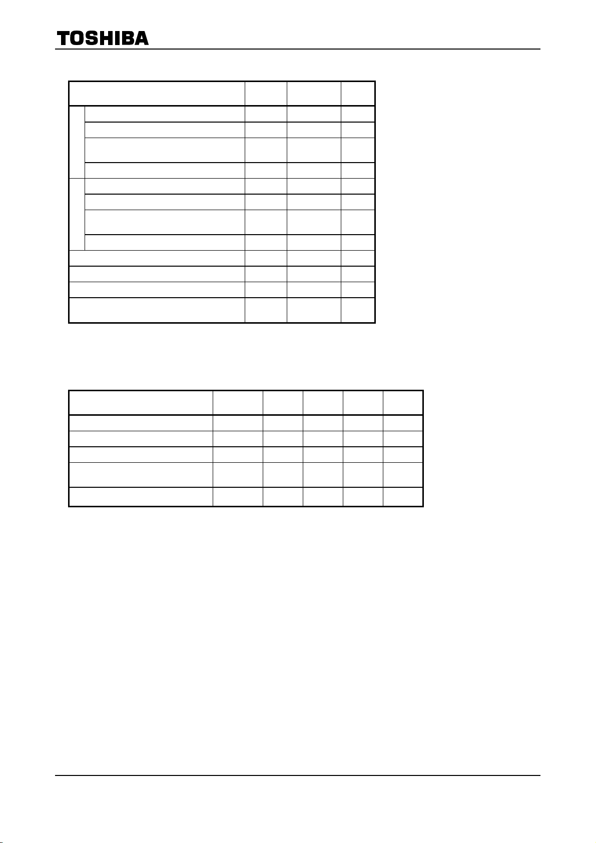
Maximum Ratings
(Ta = 25°C)
Characteristic Symbol Rating Unit
Forward current I
Pulse forward current (Note 1) I
Peak transient forward current
LED
(Note 2)
I
FPT
Reverse voltage V
Output current I
Output voltage V
Supply voltage
(1 minute maximum)
Detector
V
Output power dissipation Po
Operating temperature range T
Storage temperature range T
Lead solder temperature(10s) T
Isolation voltage
(AC, 1min., RH ≤ 60%, Note 4)
BV
(Note 1) 50% duty cycle, 1ms pulse width.
(Note 2) Pulse width ≤ 1µs, 300pps.
Recommended Operating Conditions
FP
CC
opr
stg
sol
F
R
O
O
S
20 mA
40 mA
1 A
5 V
25 mA
7 V
7 V
40 mW
-40~85 °C
-55~125 °C
260 °C
2500 Vrms
Characteristic Symbol Min. Typ. Max. Unit
Input voltage, low level VFL -3 0 1.0 V
Input current, high level IFH 13 16 20 mA
Supply voltage VCC 4.5 5 5.5 V
Fan out
(TTL load, each channel)
Operating temperature T
N ― ― 8 ―
0 ― 70 °C
opr
2
2002-09-25
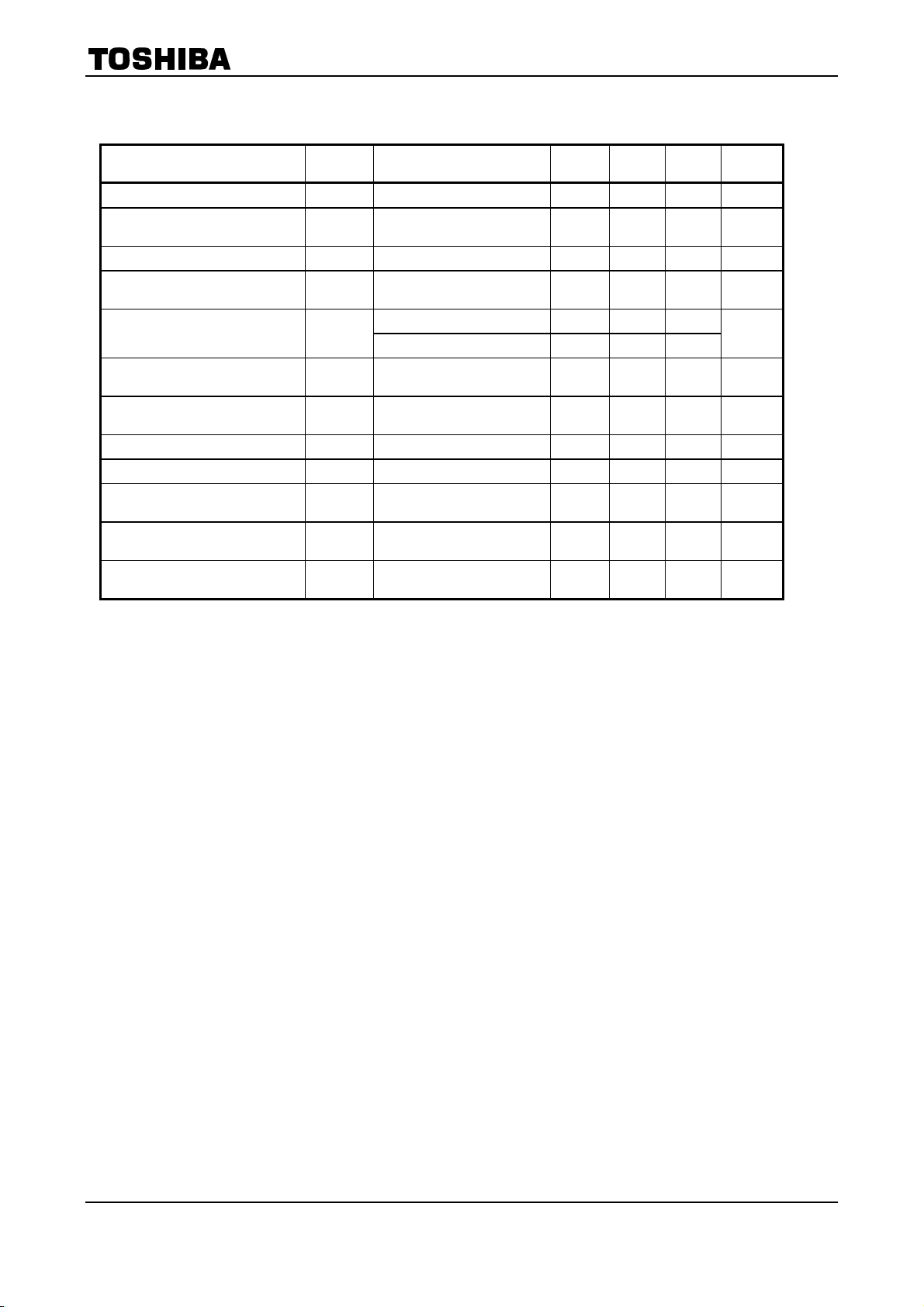
Electrical Characteristics
(unless otherwise specified, Ta = 0~70°C, V
Characteristic Symbol Test Condition Min. Typ.* Max. Unit
Forward voltage VF IF=10mA, Ta=25°C ― 1.65 1.80 V
Forward voltage
temperature coefficient
Reverse current IR VR=5V, Ta=25°C ― ― 10 µA
Capacitance between
terminals
High level output current IOH
Low level output voltage VOL
“H level output→ L level
output" input current
High level supply current I
Low level supply current I
Input-output
insulation leakage current
Isolation resistance
Stray capacitance
between input to output
V
/ Ta IF=10mA ― -2 ― mV / °C
F
C
VF=0, f=1MHz, Ta=25°C ― 45 ― pF
T
VF=1.0, VO=5.5V ― ― 250
V
=1.0, VO=5.5V, Ta=25°C ― 0.5 10
F
=10mA
I
F
I
=13mA(sinking)
OL
=13mA(sinking)
I
I
FH
CCH
CCL
I
R
C
OL
V
=0.6V
OL
VCC=5.5V, IF=0 ― 7 15 mA
VCC=5.5V, IF=16mA ― 12 18 mA
=3540V, t=5s
V
S
S
Ta=25°C (Note 4)
R.H.≤ 60%, V
S
Ta=25°C (Note 4)
=0, f=1MHz
V
S
S
Ta=25°C (Note 4)
= 4.5~5.5V, V
CC
=500V DC
S
≤
FL
― 0.4 0.6 V
― ― 10 mA
― ― 100 µA
10
5×10
― 0.8 ― pF
1.0V)
1014 ― Ω
µA
TLP115
* All typical values are VCC=5V, Ta=25°C
3
2002-09-25
 Loading...