

Page 1

Data Book
It’s first version technical data sheet.
Since this revision 0.2 is still under working, there may
be some mistakes in it.
When you will start to design, please order the latest
one.
32bit Micro controller
TLCS-900/H1 series
TMP92CZ26AXBG
TENTATIVE
Rev0.2 09/Dec./2005
Page 2

Table of Contents
TLCS-900/H1 Devices
TMP92CZ26A
1. Outline and Features ・・・・・・・・・・・・・・・・・・・・・・・・・・・・・・・・・・・・・・・・ 92CZ26A-1
2. Pin Assignment and Pin Functions ・・・・・・・・・・・・・・・・・・・・・・・・・・・・ 92CZ26A-6
2.1 Pin Assignment Diagram ・・・・・・・・・・・・・・・・・・・・・・・・・・・・・・・・ 92CZ26A-6
2.2 Pin names and Functions ・・・・・・・・・・・・・・・・・・・・・・・・・・・・・・・ 92CZ26A-8
3. Operation ・・・・・・・・・・・・・・・・・・・・・・・・・・・・・・・・・・・・・・・・・・・・・・・・・・ 92CZ26A-14
3.1 CPU ・・・・・・・・・・・・・・・・・・・・・・・・・・・・・・・・・・・・・・・・・・・・・・・・・・・ 92CZ26A-14
3.2 Memory Map ・・・・・・・・・・・・・・・・・・・・・・・・・・・・・・・・・・・・・・・・・・ 92CZ26A-19
3.3 Clock Function and Standby Function ・・・・・・・・・・・・・・・・・・・・ 92CZ26A-20
3.4 Boot ROM ・・・・・・・・・・・・・・・・・・・・・・・・・・・・・・・・・・・・・・・・・・・・・ 92CZ26A-43
3.5 Interrupts ・・・・・・・・・・・・・・・・・・・・・・・・・・・・・・・・・・・・・・・・・・・・・・ 92CZ26A-67
3.6 DMAC (DMA contro ller) ・・・・・・・・・・・・・・・・・・・・・・・・・・・・・・・・ 92CZ26A-88
3.7 Function of Ports・・・・・・・・・・・・・・・・・・・・・・・・・・・・・・・・・・・・・・・・・ 92CZ26A-110
3.7.1 Port 1 ・・・・・・・・・・・・・・・・・・・・・・・・・・・・・・・・・・・・・・・・・・・・・ 92CZ26A-117
3.7.2 Port 4 ・・・・・・・・・・・・・・・・・・・・・・・・・・・・・・・・・・・・・・・・・・・・・ 92CZ26A-119
3.7.3 Port 5 ・・・・・・・・・・・・・・・・・・・・・・・・・・・・・・・・・・・・・・・・・・・・・ 92CZ26A-121
3.7.4 Port 6 ・・・・・・・・・・・・・・・・・・・・・・・・・・・・・・・・・・・・・・・・・・・・・ 92CZ26A-123
3.7.5 Port 7 ・・・・・・・・・・・・・・・・・・・・・・・・・・・・・・・・・・・・・・・・・・・・・ 92CZ26A-125
3.7.6 Port 8 ・・・・・・・・・・・・・・・・・・・・・・・・・・・・・・・・・・・・・・・・・・・・・・ 92CZ26A-128
3.7.7 Port 9 ・・・・・・・・・・・・・・・・・・・・・・・・・・・・・・・・・・・・・・・・・・・・・・ 92CZ26A-130
3.7.8 Port A ・・・・・・・・・・・・・・・・・・・・・・・・・・・・・・・・・・・・・・・・・・・・・・ 92CZ26A-133
3.7.9 Port C ・・・・・・・・・・・・・・・・・・・・・・・・・・・・・・・・・・・・・・・・・・・・・・ 92CZ26A-135
3.7.10 Port F ・・・・・・・・・・・・・・・・・・・・・・・・・・・・・・・・・・・・・・・・・・・・・ 92CZ26A-139
3.7.11 Port G ・・・・・・・・・・・・・・・・・・・・・・・・・・・・・・・・・・・・・・・・・・・・ 92CZ26A-143
3.7.12 Port J ・・・・・・・・・・・・・・・・・・・・・・・・・・・・・・・・・・・・・・・・・・・・・ 92CZ26A-145
3.7.13 Port K ・・・・・・・・・・・・・・・・・・・・・・・・・・・・・・・・・・・・・・・・・・・・・92CZ26A-148
3.7.14 Port L ・・・・・・・・・・・・・・・・・・・・・・・・・・・・・・・・・・・・・・・・・・・ 92CZ26A-150
3.7.15 Port M ・・・・・・・・・・・・・・・・・・・・・・・・・・・・・・・・・・・・・・・・・・・ 92CZ26A-152
3.7.16 Port N ・・・・・・・・・・・・・・・・・・・・・・・・・・・・・・・・・・・・・・・・・・・・ 92CZ26A-155
3.7.17 Port P ・・・・・・・・・・・・・・・・・・・・・・・・・・・・・・・・・・・・・・・・・・・ 92CZ26A-157
3.7.18 Port R ・・・・・・・・・・・・・・・・・・・・・・・・・・・・・・・・・・・・・・・・・・・・ 92CZ26A-161
3.7.19 Port T ・・・・・・・・・・・・・・・・・・・・・・・・・・・・・・・・・・・・・・・・・・・・ 92CZ26A-164
3.7.20 Port U ・・・・・・・・・・・・・・・・・・・・・・・・・・・・・・・・・・・・・・・・・・・ 92CZ26A-166
3.7.21 Port V ・・・・・・・・・・・・・・・・・・・・・・・・・・・・・・・・・・・・・・・・・・・・ 92CZ26A-169
3.7.22 Port W ・・・・・・・・・・・・・・・・・・・・・・・・・・・・・・・・・・・・・・・・・・ 92CZ26A-172
3.7.23 Port X ・・・・・・・・・・・・・・・・・・・・・・・・・・・・・・・・・・・・・・・・・・・ 92CZ26A-174
3.7.24 Port Z ・・・・・・・・・・・・・・・・・・・・・・・・・・・・・・・・・・・・・・・・・・・・ 92CZ26A-177
3.8 Memory Controller (MEMC) ・・・・・・・・・・・・・・・・・・・・・・・・・・・・・ 92CZ26A-180
3.9 External Memory Extension Function (MMU) ・・・・・・・・・・・・・ 92CZ26A-204
3.10 SDRAM Controller (SDRAMC) ・・・・・・・・・・・・・・・・・・・・・・・・ 92CZ26A-220
3.11 NAND-Flash controller ・・・・・・・・・・・・・・・・・・・・・・・・・・・・・・・・ 92CZ26A-238
Page 3

3.12 8 bit timers (TMRA) ・・・・・・・・・・・・・・・・・・・・・・・・・・・・・・・・・・ 92CZ26A-266
3.13 16 bit timer (TMRB) ・・・・・・・・・・・・・・・・・・・・・・・・・・・・・・・・・・ 92CZ26A-294
3.14 Serial channel (SIO) ・・・・・・・・・・・・・・・・・・・・・・・・・・・・・・・・・・ 92CZ26A-315
3.15 Serial Bus Interface (SBI) ・・・・・・・・・・・・・・・・・・・・・・・・・・・・・ 92CZ26A-344
3.16 USB controller ・・・・・・・・・・・・・・・・・・・・・・・・・・・・・・・・・・・・・・ 92CZ26A-366
3.17 SPIC (SPI controller) ・・・・・・・・・・・・・・・・・・・・・・・・・・・・・・・・・ 92CZ26A-477
3.18 I2S ・・・・・・・・・・・・・・・・・・・・・・・・・・・・・・・・・・・・・・・・・・・・・・・・・ 92CZ26A-496
3.19 LCD controller (LCDC) ・・・・・・・・・・・・・・・・・・・・・・・・・・・・・・・ 92CZ26A-508
3.20 Touch screen inter face (TSI) ・・・・・・・・・・・・・・・・・・・・・・・・・・ 92CZ26A-564
3.21 Real time clock (RTC) ・・・・・・・・・・・・・・・・・・・・・・・・・・・・・・・・ 92CZ26A-574
3.22 Melody/Alarm generator ・・・・・・・・・・・・・・・・・・・・・・・・・・・・・・・ 92CZ26A-589
3.23 Analog/Digital Converter ・・・・・・・・・・・・・・・・・・・・・・・・・・・・・ 92CZ26A-595
3.24 Watch dog timer ・・・・・・・・・・・・・・・・・・・・・・・・・・・・・・・・・・・・ 92CZ26A-615
3.25 Power Management Circuit (PMC) ・・・・・・・・・・・・・・・・・・・・ 92CZ26A-619
3.26 Multiply and Accumulate Ca lculation unit (MAC) ・・・・・・・ 92CZ26A-628
3.27 Debug mode ・・・・・・・・・・・・・・・・・・・・・・・・・・・・・・・・・・・・・・・・・ 92CZ26A-633
4. Electrical Characteristics ・・・・・・・・・・・・・・・・・・・・・・・・・・・・・・・・・・・ 92CZ26A-640
5. Table of Special function registers (SFRs) ・・・・・・・・・・・・・・・・・・・・・ 92CZ26A-665
6. Package ・・・・・・・・・・・・・・・・・・・・・・・・・・・・・・・・・・・・・・・・・・・・・・・・・・・・ 92CZ26A-748
Page 4

CMOS 32-Bit Micro controllers
1. Outline and Features
TMP92CZ26A is high-speed advanced 32-bit micro-controller developed for controlling equipment which
processes mass data.
TMP92CZ26AXBG is housed in a 228-pin BGA package.
(1) CPU : 32-bit CPU(High-speed 900/H1 CPU)
• Compatible with TLCS-900/L1 instruction code
• 16Mbytes of linear address space
• General-purpose register and register banks
• Micro DMA : 8channels (62.5ns/4 bytes at f
TMP92CZ26AXBG
= 80MHz, best case)
SYS
TMP92CZ26A
(2) Minimum instruction execution time : 12.5ns ( at f
(3) Internal RAM: 288K-byte (can be used for program, data and display memory)
Internal ROM: 8 K-byte(memory for Boot only)
It enables that load user program from USB, UART to Internal RAM.
= 80MHz)
SYS
92CZ26A-1
Page 5

(4) External memory expansion
• Expandable up to 3.1G bytes (shared program/data area)
• Can simultaneously support 8/16-bit width external data bus
…… Dynamic data bus sizing
• Separate bus system
(5) Memory controller
• Chip select output : 4 channel
• One channel in 4 channels is enabled detailed AC enable setting
(6) 8-bit timers : 8 channels
(7) 16-bit timer/event counter : 2 channel
(8) General-purpose serial interface : 1 channels
• UART/synchronous mode
• IrDA ver1.0 (115.2 kbps) selectable :
(There is the restriction in the setting baud rate when use this function together other functions)
TMP92CZ26A
(9) Serial bus interface: 1 channel
2
• I
C bus mode only
(10) USB (universal serial bus) controller: 1 channel
• Support to USB (REV1.1)
• Full-speed (12 Mbps) (Low-speed is not supported.)
• Endpoint 0: Control 64 bytes × 1-FIFO
Endpoint 1: BULK (output) 64 bytes × 2-FIFO
Endpoint 2: BULK (input) 64 bytes × 2-FIFO
Endpoint 3: Interrupt (input) 8 bytes × 1-FIFO
• Descriptor RAM: 384 bytes
2
S (Inter-IC Sound)interface: 2 channel
(11) I
2
• I
S bus mode selectable (Master, transmission only)
• Data Format is supported Left/Right Justify
• Built in FIFO buffer of 128 bytes (64 bytes × 2) every each channels.
(12) LCD controller
• Supported up to monochrome, 4, 16 and 64 gray levels and 256/4096 color for STN
• Supported up to 4096/65536/262144/16777216 color for TFT
• Supported up to PIP (Picture In Picture Display)
• Supported up to H/W Rotation function for support to various LCDM
(13) SDRAM controller :1 channel
• Supported 16M, 64M, 128M, 256M and 512Mbit SDR (Single-data-rate) SDRAM
• Can use not only as Data RAM for LCD display but also operate program direct from SDRAM
(14) Timer for real-time clock (RTC)
• Based on TC8521A
(15) Key-on wakeup (Interrupt key input)
(16) 10-bit A/D converter (Built in Sample Hold circuit) : 6 channels
92CZ26A-2
Page 6

(17) Touch screen interface
• Built-in Switch of Low-resistor, and available to delete external components for shift change
row/column
(18) Watch dog timer
(19) Melody/alarm generator
• Melody: Output of clock 4 to 5461Hz
• Alarm: Output of the 8 kinds of alarm pattern
• 5 kinds of interval interrupt
(20) MMU
• Expandable up to 3.1G bytes (3 local area/8 bank method)
• Independent bank for each Program, Read-data, Write-data, Source and Destination of DMAC (Odd
channel/Even channel) and LCD-display-data
(21) Interrupts: 56 interrupts
• 9 CPU interrupts …… Software interrupt instruction and illegal instruction
• 38 internal interrupts …… Seven selectable priority levels
• 9 external interrupts …… Seven selectable priority levels
TMP92CZ26A
(8 interrupt selectable negative/positive of edge)
(22) DMAC function: 6 channels
• High-speed data transfer enable by controlling which convert micro DMA function and this function
(23) Input/Output ports : 136 pins (Except Data bus (16bit), Address bus (24bit) and RD pin)
(24) Nand_Flash interface: 2 channel
• Available to connect directly with NAND flash
• Supported up to SLC type and MLC type
• Data Bus 8/16 Bit, Page Size 512/2048 Bytes
• Built-in Rees Solomon calculation circuits which enabled correct 4-address, and detect error more
than 5-address
(25) SPI controller : 1 channel
• Supported up to SPI mode of SD card and MMC card
• Built-in FIFO buffer of 32 bytes to each Input/Output
(26) Product/Sum calculation: 1 channel
• calculation 32×32+64 =64Bit , 64-32×32 = 64Bit , 32×32-64 =64Bit
• I/O method
(27) Signed calculation is supported.
92CZ26A-3
Page 7

(28) Stand-by function
• Three Halt modes : IDLE2 (programmable), IDLE1, STOP
• Each pin status programmable for stand-by mode
• Built-in power supply management circuits (PMC) for leak current provision
(29) Clock controller
• Built-in two blocks of clock doubler (PLL). PLL supplies 48 MHz for USB and 80 MHz for CPU from
10MHz
• Clock gear function: Selectable high-frequency clock fc to fc/16
• Clock for Timer (fs = 32.768 kHz)
(30) Operating voltage:
• Internal V
• 2 power supplies (Internal power supply (1.4 to 1.6), External power supply (3.0 to 3.6)
(31) Package
• 228 pin FBGA :P-FBGA228-1515-0.80A5
= 1.5V, External I/O Vcc = 3.0 to 3.6 V
CC
TMP92CZ26A
92CZ26A-4
Page 8

(
]
(AN0 to AN1)PG0 to PG1
(
r
X
(
(
(
(
7
(
(
(
)
(
)
(
(
(
(
(
8BIT TIMER
(
r
(
(
(
(
(
(
)
(
)
(
(
)
)
)
(
)
(AN3, MY,
AN4 to AN5)PG4 to PG5
(AN2, MX)PG2
ADTRG )PG3
AVCC, AVSS
VREFH, VREFL
(PX, INT4)P96
(PY)P97
(TXD0)P90
RXD0)P91
(CTS0, SCLK0)P92
(I2S0CKO)PF0
I2S0DO)PF1
I2S0WS)PF2
(I2S1CKO)PF3
I2S1DO)PF4
I2S1WS)PF5
(SDA)PV6
(SCL)PV
(X1USB) PX5
D+
D -
(TA0IN, INT1)PC1
(TA1OUT, MLDALM)PM1
(TA2IN, INT3)PC3
TA3OUT)PP1
(TA5OUT)PP2
TA7OUT, INT5)PP3
(TB0IN0, INT6)PP4
(TB1IN0, INT7)PP5
LGOE2 to 0)PK7 to 5
LD22 to 16)PU6 to 0
LD23, EO_TRGOUT
CLKOUT, LDIV)PX4
(
SDRAS,SRLLB
(
SDCAS, SRLUB
(
(TB0OUT0)PP6
(TB1OUT0)PP7
(SPDI)PR0
(SPDO)PR1
) PR2
(
SPCS
(SPCLK)PR3
LCP0)PK0
LLOAD)PK1
LFR)PK2
LVSYNC)PK3
LHSYNC)PK4
LD7 to 0)PL7 to 0
LD15 to 8)PT7 to 0
PU7
SDWE,SRWR
(SDLLDQM)PJ3
SDLUDQM)PJ4
(SDCLK)PF7
PX7
)PJ0
)PJ1
)PJ2
SDCKE)PJ7
10-bit 6ch
AD
900/H1 CPU
Converter
Touch Screen
I/F
(TSI)
SERIAL I/O
SIO0
I2S
2
(I
S0)
I2S
2
(I
S1)
SBI (I2Cbus)
USB
XBC
XDE
XHL
XIX
XIY
XIZ
XSP
32bit
P C
XWA
A W
C B
E D
L H
IX
IY
IZ
SP
F SR
Controlle
8BIT TIMER
(TMRA0)
8BIT TIMER
(TMRA1)
8BIT TIMER
(TMRA2)
8BIT TIMER
(TMRA3)
8BIT TIMER
(TMRA4)
8BIT TIMER
(TMRA5)
8BIT TIMER
(TMRA6)
(TMRA7)
16BIT TIMER
(TMRB0)
16BIT TIMER
(TMRB1)
WATCH-DOG TIMER
MMU
MAC
DMAC
PLL
H-OSC
Clock gear
L-OSC
DSU
PMC
Interrupt
Controlle
PORT1
PORT4
PORT5
PORT6
PORT7
PORT8
SPI
Controller
288KB RAM
NAND-FLASH
I/F (2ch)
LCD
Controller
BOOT ROM 8KB
KEY-BOARD
I/F
RTC
TMP92CZ26A
DVCC3A [12]
DVCC3B [1]
DVCC1A [5]
DVCC1B [1]
DVSSCOM
DVCC1C [1]
DVSS1C [1]
X1
X2
XT1
T2
RESET
DBGE
AM[1:0
PZ0 (EI_PODDATA)
PZ1 (EI_SYNCLK)
PZ2 (EI_PODREQ)
PZ3(EI_REFCLK)
PZ4(EI_TRGIN)
PZ5(EI_COMRESET)
PZ6(EO_MCUDATA)
PZ7(EO_MCUREQ)
PM7 (PWE)
PC0 (INT0)
INT2
PC2
D0 to D7
P10 to P17 (D8 to D15)
P40 to P47(A0 to A7
P50 to P57(A8 to A15
P60 to P67
A16 to A23
P70 ( RD )
P73 (EA24)
P74 (EA25)
P75(R/
W , NDR/ B )
P76 (
WAIT )
P80 (
P81 (
P82 (
P83 (
P84 (
P85
)
0CS
1CS,SDCS
2CS,CSZA,SDCS
3CS,CSXA
)
CSZB
CSZC
)
)
P71 ( WRLL ,NDRE )
P72 (
P86 (
P87 (
,NDWE )
WRLU
,
CSZD
CSXB,CE1ND
)
CE0ND
)
PJ5 (NDALE)
PJ6
NDCLE
PA0 to PA7 (KI0 to KI7)
PN0 to PN7 (KO0 to KO7)
PC7 (KO8)
PM2
ALARM,MLDALM
)
MELODY/
ALARM-OUT
PV3
PV4
PV0 (SCLK0)
PV1
PV2
PW7 to 0
PC4 (EA26)
PC5 (EA27)
PC6 (EA28)
SDRAM
Controller
PORTV
Figure 1.1 Block Diagram of TMP92CZ26A
92CZ26A-5
Page 9
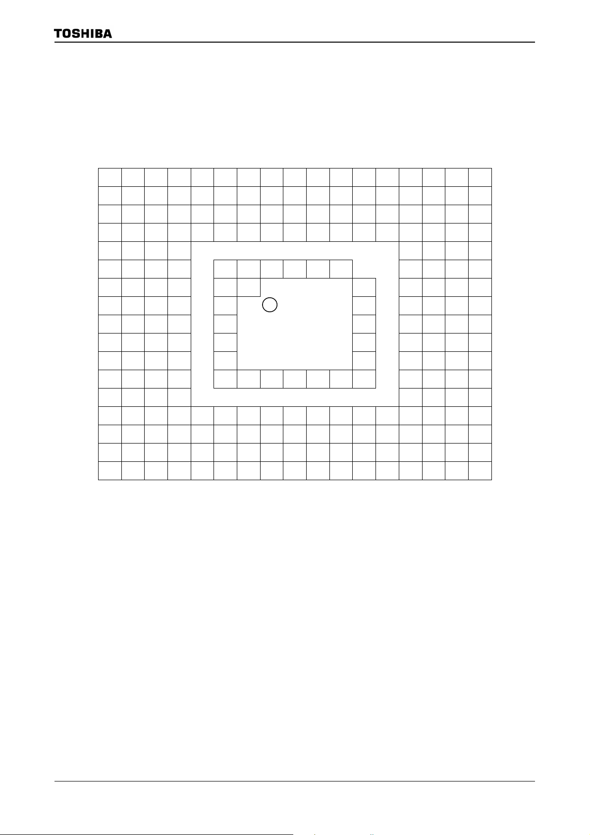
2. Pin Assignment and Pin Functions
The assignment of input/output pins for TMP92CZ26A, their names and functions are as follows;
2.1 Pin Assignment Diagram (Top View)
Figure 2.1.1 shows the pin assignment of the TMP92CZ26A.
A1 A2 A3 A4 A5 A6 A7 A8 A9 A10 A11 A12 A13 A14 A15 A16 A17
B1 B2 B3 B4 B5 B6 B7 B8 B9 B10 B11 B12 B13 B14 B15 B16 B17
C1 C2 C3 C4 C5 C6 C7 C8 C9 C10 C11 C12 C13 C14 C15 C16 C17
D1 D2 D3 D5 D6 D7 D8 D9 D10 D11 D12 D13 D15 D16 D17
E1 E2 E3 E4 E14 E15 E16 E17
F1 F2 F3 F4 F6 F7 F8 F9 F10 F11 F14 F15 F16 F17
G1 G2 G3 G4 G6 G7 G12 G14 G15 G16 G17
H1 H2 H3 H4 H6 H12 H14 H15 H16 H17
TMP92CZ26A
J1 J2 J3 J4 J6 J12 J14 J15 J16 J17
K1 K2 K3 K4 K6 K12 K14 K15 K16 K17
L1 L2 L3 L4 L6 L12 L14 L15 L16 L17
M1 M2 M3 M4 M6 M7 M8 M9 M10 M11 M12 M14 M15 M16 M17
N1 N2 N3 N4 N14 N15 N16 N17
P1 P2 P3 P5 P6 P7 P8 P9 P10 P11 P12 P13 P15 P16 P17
R1 R2 R3 R4 R5 R6 R7 R8 R9 R10 R11 R12 R13 R14 R15 R16 R17
T1 T2 T3 T4 T5 T6 T7 T8 T9 T10 T11 T12 T13 T14 T15 T16 T17
U1 U2 U3 U4 U5 U6 U7 U8 U9 U10 U11 U12 U13 U14 U15 U16 U17
Figure 2.1.1 Pin assignment diagram (P-FBGA228)
4 balls of A1, A17, U1 and U17 (most outside 4 corner of BGA package) are Dummy Balls.
These balls are not connected with internal LSI chip, electr ical characteristics.
A1 and U1, A17 and U17 are shorted in internal package. It is recommended that using to
OPEN check of mounting if mounting this LSI to Target board.
TMP92CZ26A
P-FBGA228
TOP VIEW
Example: If checking signal (or voltage) via A1-U1-U17-A17, short U17 and U1 on Target board
beforehand, and input signal (or voltage) from A1, and check voltage of A17.
92CZ26A-6
Page 10
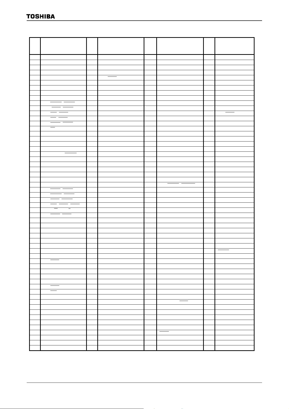
TMP92CZ26A
Table 2.1.1 Pin number and the name
Ball
No.
A1 Dummy1 D9 P73,EA24 J15 PT5,LD13 P15 PK4,LHSYNC
A2 PG2,AN2, MX D10 PF4,I2S1DO J16 P47,A7 P16 P13,D11
A3 PA6,KI6 D11 PF7,SDCLK J17 P46,A6 P17 P14,D12
A4 PA5,KI5 D12 PJ4,SDLUDQM K1 PN3,KO3 R1 X2
A5 PA3,KI3 D13 P85,
A6 PA1,KI1 D15 PU6,LD22 K3 PN5,KO5 R3 PC3,INT3,TA2IN
A7 DVCC1A5 D16 P61,A17 K4 PN6,KO6 R4 PX5,X1USB
A8 PF1,I2S0DO D17 P60,A16 K6 DVCC3A2 R5 PP7,TB1OUT0
A9 PJ6,NDCLE E1 P96,PX,INT4 K12 DVCC3A7 R6 PP1,TA3OUT
A10 PJ1,
A11 P87,
A12 P83,
A13 P81,
A14 P72,
A15 P70,RD E16 P57,A15 L2 PN7,KO7 R12 PZ2,EI_PODREQ
A16 P65,A21 E17 P56,A14 L3 PM1,MLDALM,TA1OUT R13 PZ4,EI_TRGIN
A17 Dummy3 F1 DVCC1B1 L4 PM7,PWE R14 PZ6,EO_MCUDATA
B1 VREFH F2 PW6 L6 DVSS3 R15 PZ7,EO_MCUREQ
B2 PG5,AN5 F3 PW5 L12 DVSS7 R16 P15,D13
B3 PG3,AN3,MY,
B4 PA7,KI7 F6 DVCC3A12 L15 PT1,LD9 T1 X1
B5 PA2,KI2 F7 DVCC3A11 L16 P43,A3 T2 AM0
B6 PA0,KI0 F8 DVSS11 L17 P42,A2 T3 AM1
B7 PF2,I2S0WS F9 DVCC3A10 M1 PK3,LVSYNC T4 PP6,TB0OUT0
B8 PF0,I2S0CKO F10 DVSS10 M2 PC0,INT0 T5 PL0,LD0
B9 PJ5,NDALE F11 DVCC3A9 M3 PM2,
B10 PJ2,
B11 PJ0,
B12 P86.
B13 P82,
B14 P75,R/W,NDR/B G1 DVCC3B1 M9 DVSS5 T11 PK1,LLOAD
B15 P71,
B16 P64,A20 G3 PV0,SCLK0 M11 DVSS6 T13 P02,D2
B17 DVCC1A4 G4 PV1 M12 DVCC3A6 T14 P04,D4
C1 AVCC G6 DVSS1 M14 PK7,LGOE2 T15 P06,D6
C2 VREFL G7 DVSS12 M15 PT0,LD8 T16 P11,D9
C3 PG4,AN4 G12 DVSS9 M16 P41,A1 T17 P12,D10
C4 PG1,AN1 G14 PU3,LD19 M17 P40,A0 U1 Dummy2
C5 PA4,KI4 G15 PU0,LD16 N1 DVCC1A1 U2
C6 PC5,EA27 G16 P53,A11 N2 PC1,INT1,TA0IN U3 D+
C7 P76,
C8 PF5,I2S1WS H1 PV7,SCL N4 DVSS1C U5 DVCC1A2
C9 PF3,I2S1CKO H2 PV6,SDA N14 PK6,LGOE1 U6 PL1,LD1
C10 PJ7,SDCKE H3 PV3 N15 PK5,LGOE0 U7 PL3,LD3
C11 PJ3,SDLLDQM H4 PV2 N16 P17,D15 U8 XT1
C12 P84,
C13 P80,
C14 P67,A23 H14 PU1,LD17 P2 PC2,INT2 U11 PK0,LCP0
C15 P66,A22 H15 PT7,LD15 P3 P92,SCLK0,
C16 P63,A19 H16 P51,A9 P5 PX4,CLKOUT, LDIV U13 P03,D3
C17 P62,A18 H17 P50,A8 P6 PP2,TA5OUT U14 P05,D5
D1 P97,PY J1 PN2,KO2 P7 PP4,INT6,TB0IN0 U15 P07,D7
D2 AVSS J2 PN1,KO1 P8 PR0,SPDI U16 P10,D8
D3 PW0 J3 PN0,KO0 P9 PR3,SPCLK U17 Dummy4
D5 PG0,AN0 J4 PV4 P10
D6 PC6,EA28 J6 DVSS2 P11 PZ1,EI_SYNCLK
D7 PC4,EA26 J12 DVSS8 P12 PZ3,EI_REFCLK
D8 P74,EA25 J14 PT6,LD14 P13 PZ5,EI_COMRESET
Pin name
SDCAS,SRLUB
CSXB,CE1ND
3CS,CSXA
1CS,SDCS
WRLU
SDWE,SRWR
SDRAS,SRLLB
CSZD,CE0ND
2CS,CSZA,SDCS
WRLL,NDRE
G17 P52,A10 N3 P91,RXD0 U4 D-
WAIT
CSZB
H12 DVCC3A8 P1 DVCC1C U10 PL7.LD7
0CS
E3 PW2 K15 PT3,LD11 R8 PP5,INT7,TB1IN0
E4 PW3 K16 P45,A5 R9 PR2,
E14 PU7,LD23,EO_TRGOUT K17 P44,A4 R10 PX7
,
E15 PU4,LD20 L1 PK2,LFR R11 PZ0,EI_PODDATA
NDWE
ADTRG
F14 PU5,LD21 M4 P90,TXD0 T7 PL4,LD4
F16 P55,A13 M7 DVSS4 T9 PR1,SPDO
G2 PW7 M10 DVCC3A5 T12 P00,D0
H6 DVCC3A1 N17 P16,D14 U9 XT2
Ball
No.
E2 PW1 K14 PT4,LD12 R7 PP3,INT5,TA7OUT
F4 PW4 L14 PT2,LD10 R17 DVCC1A3
F15 PU2,LD18 M6 DVCC3A3 T8 PL5,LD5
F17 P54,A12 M8 DVCC3A4 T10 PL6,LD6
Pin name
K2 PN4,KO4 R2 PC7,KO8
CSZC
Ball
No.
Pin name
ALARM,MLDALM
U12 P01,D1
0CTS
DBGE
Ball
No.
T6 PL2,LD2
RESET
Pin name
SPCS
Note1: The P96, P97 and PG0~PG5 operate with the AVCC power supply.
Note2: The PW0~PW7 and PV0~PV7 operate with the DVCC3B power supply.
Note3: The X1 and X2 operate with the DVCC1C power supply.
92CZ26A-7
Page 11

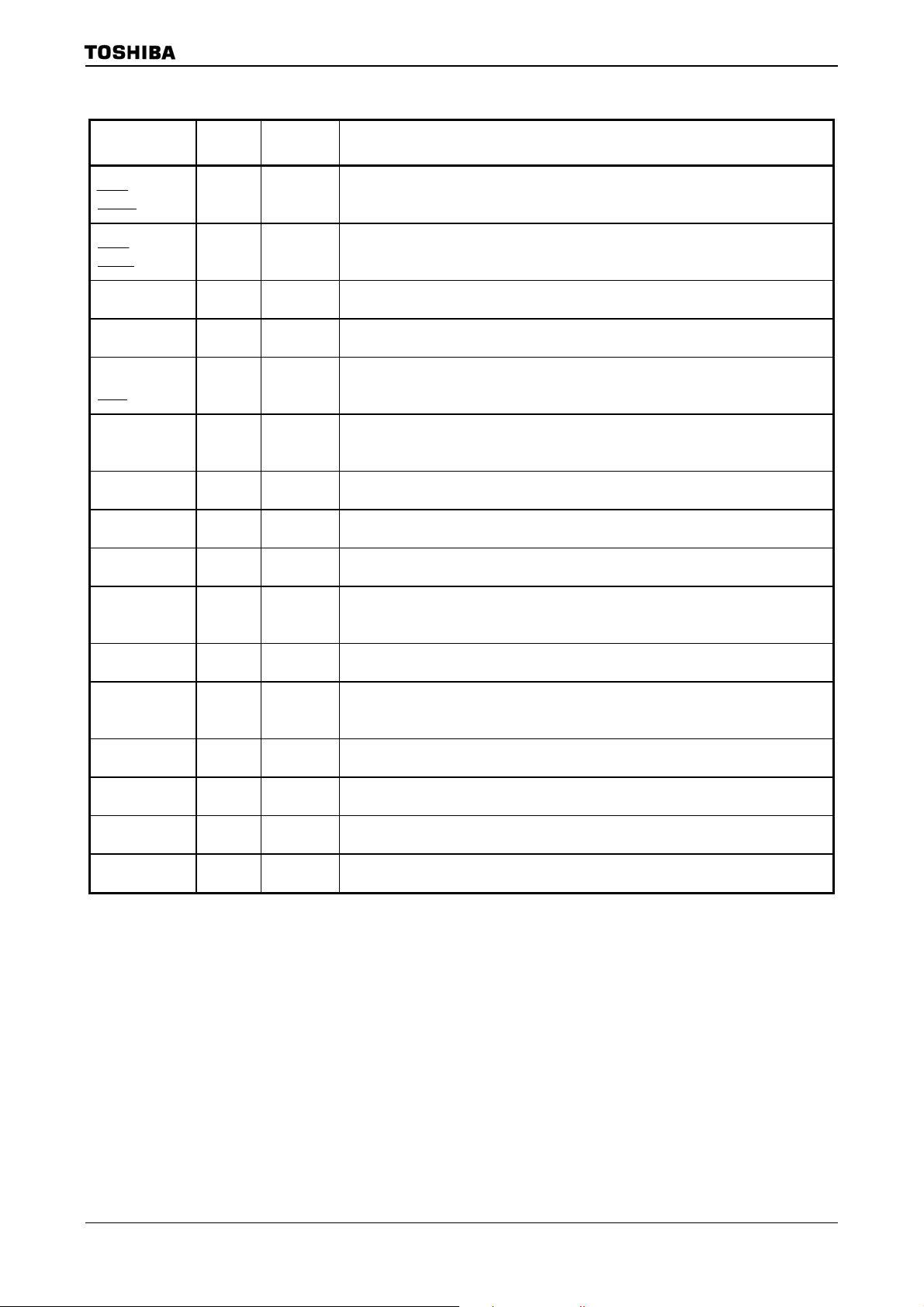
2.2 Pin names and Functions
The names of the input/output pins and their functions are described below.
Table 2.2.1 Pin names and functions (1/6)
TMP92CZ26A
Pin name
D0 to D7 8 I/O Data: Data bus D0 to D7.
P10 to P17
D8 to D15
P40 to P47
A0 to A7
P50 to P57
A8 to A15
P60 to P67
A16 to A23
P70
RD
P71
WRLL
NDRE
P72
WRLU
NDWE
P73
EA24
P74
EA25
P75
R/
W
NDR/
B
P76
WAIT
P80
0CS
P81
1CS
SDCS
P82
2CS
CSZA
SDCS
P83
3CS
CSXA
P84
CSZB
P85
CSZC
Number of
Pins
8
8
8
8
1 Output
1 I/O
1 I/O
1 I/O
1 I/O
1 I/O
1
1
1 Output
1 Output
1 Output
1 Output
1 Output
I/O Functions
I/O
I/O
Output
Output
Output
Output
I/O
Output
Output
Output
Output
Output
Output
Output
Output
Output
Input
I/O
Input
Output
Output
Output
Output
Output
Output
Output
Output
Output
Output
Output
Port 1: I/O port. Input or output is specifiable in units of bit.
Data : Data bus D8 to D15.
Port 4: Output port.
Address : Address bus A0 to A7.
Port 5: Output port.
Address : Address bus A8 to A15.
Port 6 : I/O port. Input or output is specifiable in units of bit.
Address : Address bus A16 to A23.
Port 70 : Output port.
Read : Outputs strobe signal to read external memory.
Port 71 : Output port.
Write : Outputs strobe signal to write data on pins D0 to D7.
NAND Flash read : Outputs strobe signal to read external NAND-Flash.
Port 72 : I/O port.
Write : Outputs strobe signal to write data on pins D8 to D15.
NAND Flash write : Write enable for NAND Flash.
Port 73 : I/O port.
Expanded address 24.
Port 74 : I/O port.
Expanded address 25.
Port 75 : I/O port.
Read/Write : “High” represents read or dummy cycle and “Low” write cycle.
NAND Flash Ready(1) / Busy(0) input.
Port 76: I/O port.
Wait: Signal used to request CPU bus wait.
Port 80: Output port.
Chip select 0: Outputs “Low” when address is within specified address area.
Port 81 : Output port
Chip select 1: Outputs “Low” when address is within specified address area.
Chip select for SDRAM : Outputs “Low” when the address is within SDRAM address area.
Port 82 : Output port.
Chip select 2: Outputs “Low” when address is within specified address area.
Expanded address ZA : Outputs “Low” when address is within specified address area.
Chip select for SDRAM : Outputs “0” when the address is within SDRAM address area.
Port 83 : Output port.
Chip select 3: Outputs “Low” when address is within specified address area.
Expanded address XA : Outputs “Low” when address is within specified address area.
Port 84 : Output port.
Expanded address ZB : Outputs “Low” when address is within specified address area.
Port 85 : Output port.
Expanded address ZC : Outputs “Low” when address is within specified address area.
92CZ26A-8
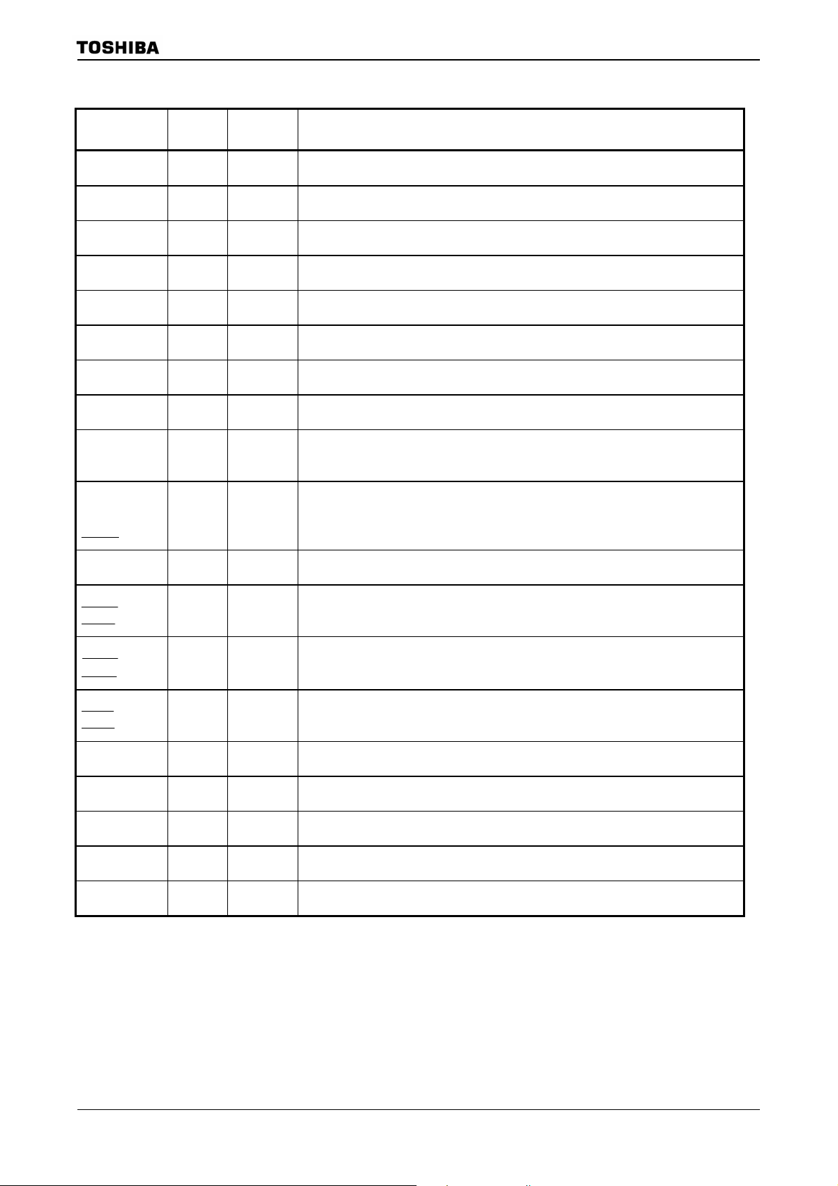
Page 12
TMP92CZ26A
Pin name
P86
CSZD
CE0ND
P87
CSXB
CE1ND
P90
TXD0
P91
RXD0
P92
SCLK0
0CTS
P96
INT4
PX
P97
PY
PA0 to PA7
KI0 to KI7
PC0
INT0
PC1
INT1
TA0IN
PC2
INT2
PC3
INT3
TA2IN
PC4
EA26
PC5
EA27
PC6
EA28
PC7
KO8
Table 2.2.1 Pin names and functions (2/6)
Number
of Pins
1
1
1
1
1
1 Input
1 Input
8
1
1
1
1
1
1
1
1
I/O Functions
Output
Output
Output
Output
Output
Output
I/O
Output
I/O
Input
I/O
I/O
Input
Input
Output
Output
Input
Input
I/O
Input
I/O
Input
Input
I/O
Input
I/O
Input
Input
I/O
Output
I/O
Output
I/O
Output
I/O
Output
Port 86 : Output port.
Expanded address ZD : Outputs “Low” when address is within specified address area.
Chip select of NAND Flash 0: Outputs “Low” when NAND Flash 0 is enable.
Port 87 : Output port.
Expanded address XB : Outputs “Low” when address is within specified address area.
Chip select of NAND Flash 1: Outputs “Low” when NAND Flash 1 is enable.
Port 90: I/O port.
Transmit data of serial 0: programmable open drain output.
Port 91: I/O port. (Schmitt input)
Receive data of serial 0.
Port 92: I/O port. (Schmitt input)
Clock I/O of serial 0
Enable to send data of serial 0 (Clear to send).
Port 96: Input port. (schmitt input, with pull-up resistor)
Interrupt request pin 4 : Interrupt request pin with programmable rising/falling edge.
X-Plus : Pin connected to X+ pin for Touch Screen I/F.
Port 97: Input port. (schmitt input)
Y-Plus : Pin connected to Y+ pin for Touch Screen I/F.
Port A0 to A7: Input port.
Key input 0 to 7: For key on wake-up 0 to 7. (Schmitt input, with pull-up resistor)
Port C0: I/O port. (Schmitt input)
Interrupt request pin 0 : Interrupt request pin with programmable rising/falling edge.
Port C1: I/O port. (Schmitt input)
Interrupt request pin 1 : Interrupt request pin with programmable rising/falling edge.
Timer A0 input: Input pin of 8 bit timer 0.
Port C2: I/O port. (Schmitt input)
Interrupt request pin 2 : Interrupt request pin with programmable rising/falling edge.
Port C3: I/O port. (Schmitt input)
Interrupt request pin 3 : Interrupt request pin with programmable rising/falling edge.
Timer A2 input: Input pin of 8 bit timer 2.
Port C4: I/O port.
Expanded address 26.
Port C5: I/O port.
Expanded address 27.
Port C6: I/O port.
Expanded address 28.
Port C7: I/O port.
Key output 8: Key scan strobe pin (programmable open drain output).
92CZ26A-9
Page 13
TMP92CZ26A
Table 2.2.1 Pin names and functions (3/6)
Pin name
PF0
I2S0CKO
PF1
I2S0DO
PF2
I2S0WS
PF3
I2S0WS
PF4
I2S1CKO
PF5
I2S1WS
PF7
SDCLK
PG0 to PG1
AN0 to AN1
PG2
AN2
MX
PG3
AN3
MY
ADTRG
PG4 to PG5
AN4 to AN5
PJ0
SDRAS
SRLLB
PJ1
SDCAS
SRLUB
PJ2
SDWE
SRWR
PJ3
SDLLDQM
PJ4
SDLUDQM
PJ5
NDALE
PJ6
NDCLE
PJ7
SDCKE
Number of
Pins
1
1
1
1
1
1
1
2
1
1
2
1
1
1
1
1
1
1
1
I/O Functions
I/O
Output
I/O
Output
I/O
Output
I/O
Output
I/O
Output
I/O
Output
Output
Output
Input
Input
Input
Input
Output
Input
Input
Output
Input
Input
Input
Output
Output
Output
Output
Output
Output
Output
Output
Output
Output
Output
Output
Output
I/O
Output
I/O
Output
Output
Output
Port F0: I/O port.
Outputs clock of I2S0.
Port F1: I/O port.
Outputs data of I2S0.
Port F2: I/O port.
Outputs word select signal of I2S0.
Port F3: I/O port.
Outputs clock of I2S1.
Port F4: I/O port.
Outputs data of I2S1.
Port F5: I/O port.
Outputs word select signal of I2S1.
Port F7: Output port.
Clock for SDRAM.
Port G0 to G1: Input port.
Analog input pin 0 to 1 : Input pin of A/D converter.
Port G2: Input port.
Analog input pin 2 : Input pin of A/D converter.
X-Minus : Pin connected to X- pin for Touch Screen I/F.
Port G3: Input port.
Analog input pin 3 : Input pin of A/D converter.
Y-Minus : Pin connected to Y- pin for Touch Screen I/F.
A/D Trigger : Request signal of A/D start.
Port G4 to G5: Input port.
Analog input pin 4 to 5 : Input pin of A/D converter.
Port J0: Output port.
Outputs strobe signal of SDRAM row address.
Data enable signal for D0 to D7 of SRAM.
Port J1: Output port.
Outputs strobe signal of SDRAM column address.
Data enable signal for D8 to D15 of SRAM.
Port J2: Output port.
Outputs write enable signal of SDRAM.
Write enable of SRAM: Outputs strobe signal to write data.
Port J3: Output port.
Data enable signal for D0 to D7 of SDRAM.
Port J4: Output port.
Data enable signal for D8 to D15 of SDRAM.
Port J5: I/O port.
Address latch enable signal of NAND Flash.
Port J6: I/O port.
Command latch enable signal of NAND Flash.
Port J7: Output port.
Clock enable signal of SDRAM.
92CZ26A-10
Page 14
TMP92CZ26A
Table 2.2.1 Pin names and functions (4/6)
Pin name
PK0
LCP0
PK1
LLOAD
PK2
LFR
PK3
LVSYNC
PK4
LHSYNC
PK5
LGOE0
PK6
LGOE1
PK7
LGOE2
PL0 to PL7
LD0 to LD7
PM1
TA1OUT
MLDALM
PM2
ALARM
SPCS
MLDALM
PM7
PWE
PN0 to PN7
KO0 to KO7
PP1
TA3OUT
PP2
TA5OUT
PP3
INT5
TA7OUT
PP4
INT6
TB0IN0
PP5
INT7
TB1IN0
PP6
TB0OUT0
PP7
TB1OUT0
PR0
SPDI
PR1
SPDO
PR2
Number of
Pins
1
1
1
1
1
1
1
1
8
1
1
1
8
1
1
1
1
1
1
1
1
1
1
I/O Functions
Output
Output
Output
Output
Output
Output
Output
Output
Output
Input
Output
Output
Output
Output
Output
Output
Output
Output
Output
Output
Output
Output
Output
Output
Output
Output
I/O
Output
I/O
Output
I/O
Output
I/O
Input
Output
I/O
Input
Input
I/O
Input
Input
Output
Output
Output
Output
I/O
Input
I/O
Output
I/O
Output
Port K0: Output port.
Signal for LCD driver.
Port K1: Output port.
Signal for LCD driver.: Data load signal
Port K2: Output port.
Signal for LCD driver.
Port K3: Output port.
Signal for LCD driver. : Vertical sync signal
Port K4: Output port.
Signal for LCD driver. : Horizontal sync signal.
Port K5: Output port.
Signal for LCD driver.
Port K6: Output port.
Signal for LCD driver.
Port K7: Output port.
Signal for LCD driver.
Port L0 to L7: Output port.
Data bus for LCD driver: LD0 to LD7.
Port M1: Output port.
Timer A1 output: Output pin of 8 bit timer 1.
Melody / Alarm output pin.
Port M2: Output port.
Alarm output from RTC.
Melody / Alarm output pin (inverted).
Port M7 : Output port
External power supply control output: Pin to control ON/OFF of external power
supply. In st and-by mode, outputs “L” level. In other than stand-by mode, outputs
“H” level.
Port N: I/O port.
Key output 0 to 7 : Key scan strobe pin (programmable open drain output).
Port P1: I/O port.
Timer A3 output: Output pin of 8 bit timer 3.
Port P2: I/O port.
Timer A5 output: Output pin of 8 bit timer 5.
Port P3: I/O port. (Schmitt input)
Interrupt request pin 5 : Interrupt request pin with programmable rising/falling edge.
Timer A7 output: Output pin of 8 bit timer 7.
Port P4: I/O port. (Schmitt input)
Interrupt request pin 6 : Interrupt request pin with programmable rising/falling edge.
Timer B0 input: Input pin of 16 bit timer 0.
Port P5: I/O port. (Schmitt input)
Interrupt request pin 7 : Interrupt request pin with programmable rising/falling edge.
Timer B1 input: Input pin of 16 bit timer 1.
Port P6: I/O port.
Timer B0 output: Output pin of 16 bit timer 0.
Port P7: I/O port.
Timer B1 output: Output pin of 16 bit timer 1.
Port R0: I/O port.
Data input pin of SD card.
Port R1: I/O port.
Data output pin of SD card.
Port R2: I/O port.
Chip select signal of SD card.
92CZ26A-11
Page 15
TMP92CZ26A
Table 2.2.1 Pin names and functions (5/6)
Pin name
PR3
SPCLK
PT0 to PT7
LD8 to LD15
PU0 to PU4,PU6
LD16 to LD20,LD22
PU5
LD21
PU7
LD23
EO_TRGOUT
PV0
SCLK0
PV1 1 I/O Port V1: I/O port.
PV2 1 I/O Port V2: I/O port.
PV3 to PV4 2 Output Port V3 to V4: Output port.
PV6
SDA
PV7
SCL
PW0 to PW7 8 I/O Port W0 to W7: I/O port.
PX4
CLKOUT
LDIV
PX5
X1USB
PX7 1 I/O Port X7: I/O port.
PZ0
EI_PODDATA
PZ1
EI_SYNCLK
PZ2
EI_PODREQ
PZ3
EI_REFCLK
PZ4
EI_TRGIN
PZ5
EI_COMRESET
PZ6
EO_MCUDATA
PZ7
EO_MCUREQ
Number of
Pins
1
8
6
1
1
1
1
1
1
1
1
1
1
1
1
1
1
1
I/O Functions
I/O
Output
I/O
Output
I/O
Output
I/O
Output
I/O
Output
Output
I/O
Output
I/O
I/O
I/O
I/O
Output
Output
Output
I/O
Input
I/O
Input
I/O
Input
I/O
Input
I/O
Input
I/O
Input
I/O
Input
I/O
Output
I/O
Output
Port R3: I/O port.
Clock output pin of SD card.
Port T0 to T7: I/O port.
Data bus for LCD driver: LD8 to LD15.
Port U0 to U4 , U6: I/O port
Data bus for LCD driver: LD16 to LD20, LD22.
Port U5: I/O port
Data bus for LCD driver: LD21
Port U7: I/O port
Data bus for LCD driver: LD23
Debug mode output pin
Port V0 : I/O port
Clock I/O of serial 0.
Port V6: I/O port
Send/receive data in I
Port V7: I/O port
Input/output clock in I
Port X4 : Output port
Internal clock output pin
Output pin for LCD driver
Port X5: I/O port.
Clock input pin of USB.
Port Z0: I/O port. (Schmitt input)
Debug mode input pin
Port Z1: I/O port. (Schmitt input)
Debug mode input pin
Port Z2: I/O port. (Schmitt input)
Debug mode input pin
Port Z3: I/O port. (Schmitt input)
Debug mode input pin
Port Z4: I/O port. (Schmitt input)
Debug mode input pin
Port Z5: I/O port. (Schmitt input)
Debug mode input pin
Port Z6: I/O port. (Schmitt input)
Debug mode output pin
Port Z7: I/O port. (Schmitt input)
Debug mode output pin
2
C mode.
2
C mode.
92CZ26A-12
Page 16
TMP92CZ26A
Table 2.2.1 Pin names and functions (6/6)
Pin name
D+, D- 2 I/O
CLKOUT 1 Output Internal clock output pin.
AM1,AM0 2 Input
DBGE
X1/X2 2 I/O High-frequency oscillator circuit connection pin.
XT1/XT2 2 I/O Low-frequency oscillator circuit connection pin.
RESET
VREFH 1 Input Pin for reference voltage input to A/D converter(H).
VREFL 1 Input Pin for reference voltage input to A/D converter(L).
AVCC 1
AVSS 1
DVCC3A 12
DVCC3B 1
DVCC1A 5
DVCC1B 1
DVSSCOM 12
DVCC1C 1
DVSS1C 1
Dummy4-1 4
Number of
Pins
1 Input Input pin in debug mode. (This pin is set to “Debug mode” by input “0”.)
1 Input Reset : Initialize TMP92CZ26A (schmitt input , with pull-up resistor)
I/O Functions
Data pin connected to USB.
In case USB is not used, connect both pins to pull-up(DVCC3A) or pull-down resistor for protect
current flows it.
Operation mode;
Fix to AM1=”0”,AM0=”1” for 16 bit external bus starting.
Fix to AM1=”1”,AM0=”0” is prohibit to set.
Fix to AM1=”1”,AM0=”1” for BOOT (32 bit internal Mask ROM) starting.
Fix to AM1=”0”,AM0=”0” is prohibited to set.
−
−
−
−
−
−
−
−
−
−
Power supply pin for A/D converter.
GND pin for AD converter (0V).
Power supply pin for peripheral I/O-A (Connect all DVCC3A pins to power supply pin.)
Power supply pin for peripheral I/O-B (Connect all DVCC3B pins to power supply pin.)
Power supply pin for internal logic-A. (Connect all DVCC1A pins to power supply pin.)
Power supply pin for internal logic-B. (Keep the voltage DVCC1A level.)
GND pin (0V). (Connect all DVSS pins to GND(0V).)
Power supply pin for High speed oscillator. (Keep the voltage DVCC1A level.)
GND pin (0V). (Connect to GND(0V).)
Dummy1 and Dummy2, Dummy3 and Dummy4 are shorted in package. (These pins are not
connected with internal LSI chip.)
Tabl e 2.2.2 shows the range of operational voltage for power supply pins.
Table 2.2.2 the range of operational voltage for power supply pins
Range of
Power supply pin
operational
voltage
DVCC1A
DVCC1B
DVCC1C
DVCC3A
DVCC3B
AVCC
1.4V~1.6V
3.0V~3.6V
92CZ26A-13
Page 17

3. Operation
This section describes the basic components, functions and operation of the TMP92CZ26A.
3.1 CPU
The TMP92CZ26A c onta ins an ad vanced high-speed 32-bit CPU (900/H1 CPU)
3.1.1 CPU Outline
900/H1 CPU is high-speed and high-performance CPU based on 900/L1 CPU. 900/H1
CPU has expanded 32-bit internal data bus to process Instructions more quickly.
Outline is as follows:
TMP92CZ26A
Table 3.1.1Outline of TMP92CZ26A
Parameter TMP92CZ26A
Width of CPU Address Bus 24-bit
Width of CPU Data Bus 32-bit
Internal Operating Frequency Max 80MHz
Minimum Bus Cycle 1-clock access
(12.5ns at 80MHz)
Internal RAM 32-bit 2-1-1-1 clock access
Internal Boot ROM 32 bit 2-clock access
Internal I/O
8-bit,
2-clock access
16-bit,
2-clock access
32-bit,
2-clock access
INTC,SDRAMC,
MEMC,LCDC,
TSI,PORT,
PMC
MMU,USB,
NDFC,SPIC,DMAC
I2S
MAC
32-bit,
1-clock access
8-bit,
5 to 6-clock access
External memory
(SRAM, MASKROM etc.)
External memory
(SDRAM)
External memory
(NAND FLASH)
Minimum Instruction
Execution Cycle
Conditional Jump 2-clock(25.0ns at 80MHz)
Instruction Queue Buffer 12-byte
Instruction Set Compatible with TLCS-900/L1
CPU mode Only maximum mode
Micro DMA 8-channel
Hardware DMA 6-channel
8/16-bit 2-clock access
(can insert some waits)
16-bit 1-clock access
8/16-bit 2-clock access
(can inset some waits)
1-clock(12.5ns at 80MHz)
(LDX instruction is deleted)
MAC
TMRA,TMRB,
SIO,RTC,
MLD/ALM, SBI
CGEAR,ADC,WDT
92CZ26A-14
Page 18

3.1.2 Reset Operation
When resetting the TMP92CZ26A microcontroller, ensure that the power supply voltage
is within the operating voltage range, and that the internal high-frequency oscillator has
stabilized. Then hold the
X1=10MHz).
At reset, since the clock doublers (PLL0) is bypassed and clock-gear is set to 1/16, system
clock operates at 625 kHz(X1=10MHz).
When the Reset has been accepted, the CPU performs the following. CPU internal
registers do not change when the Reset is released.
• Sets the Stack Pointer (XSP) to 00000000H.
• Sets bits <IFF2:0> of the Status Register (SR) to “111” (thereby setting the Interrupt
Level Mask Register to level 7).
• Clears bits <RFP1:0> of the Status Register to 00 (thereby selecting Register Bank 0).
When the Reset is released, the CPU starts executing instructions according to the
Program Counter settings.
• Sets the Program Counter (PC) as follows in accordance with the Reset Vector stored
at address FFFF00H~FFFF02H:
TMP92CZ26A
RESET input Low for at least 20 system clocks (32µs at
PC<7:0> ← data in location FFFF00H
PC<15:8> ← data in location FFFF01H
PC<23:16> ← data in location FFFF02H
When the Reset is accepted, the CPU sets internal I/O, ports and other pins as follows.
• Initializes the internal I/O registers as table of “Special Function Register” in Section
5.
Note1: This LSI builds in RAM internally. However, the data in internal RAM may not be held by Reset
operation. After reset, initialize the data in internal RAM.
Note2: This LSI builds in PMC function (for reducing stand-by current by blocking the power supply of
DVCC1A and DVCC1C). However, if executing reset operation without supplying DVCC1A and
DVCC1C, the current may flow to internal. When reset this LSI, supply the power of DVCC1A and
DVCC1C first and wait until the power supply stabilizes.
Figure 3.1.2 shows reset timing chart. Figure 3.1.2 shows the example of or der of supplying
power and the timing of releasing reset.
92CZ26A-15
Page 19

A
TMP92CZ26A
Read
Write
0FFFF00H
DATA-IN
(After reset is released, it is started
from 1 wait read cycle)
×(15.5∼16.5) Clock
SYS
f
Sampling
Sampling
sys
RESET
f
23∼0
CS2
CS0,1, 3
Figure 3.1.1 TMP92CZ26A Reset timing chart
DATA-IN
D0∼15
RD
SRxxB
DATA-OUT
D0∼15
WRxx
SRWR
: High-Z
SRxxB
92CZ26A-16
Page 20

)
1.5V
Power
3.3V
Power
This LSI has the restriction for the order of supplying power. Be sure to supply external
3.3V power with 1.5V power is supplied.
DVCC1A
DVCC1B
DVCC1C
After 1.5V power
supply is rising,
set 3.3V to ON.
DVCC3A
DVCC3B
AVCC
RESET
Power On
Power supply is rising with
in 100mS, and stabilizes.
High-frequency oscillation
stabilization time
+20 system clock
Stand-by Mode (PMC
Power supply is falling with
in 100mS, and stabilizes.
TMP92CZ26A
Power Off
After 1.5V power
supply is falling, set
3.3V to OFF.
PWE terminal
Note1: Inernal 1.5 V and External 3.3V power supply can be set to ON/OFF at the same time. However, external pin
may become unstable condition momentary. Therefore, set external power supply to ON/OFF during internal
power supply is stabile like above figure if there is possibility to affect machinery connected with micro controller.
Note2: When setting to ON, don’t set 3.3V power supply earlier than 1.5V power supply. When setting to OFF, don’t
set to 3.3V power supply later than 1.5 V power supply.
Figure 3.1.2 Power on Reset Timing Example
92CZ26A-17
Page 21
3.1.3 Setting of AM0 and AM1
Set AM1 and AM0 pins as Table 3.1.2 shows according to system usage.
Mode Setup input pin
RESET
AM1 AM0
0 1
1 0
1 1
0 0
Table 3.1.2 Operation Mode Setup Table
DBGE
0 Debug mode
1
0
1
0
1
0
1
Operation Mode
16-bit external bus starting
Test mode (Prohibit to set)
Test mode (Prohibit to set)
BOOT(32-bit internal-MROM )
starting
(BOOT mode)
Test mode (Prohibit to set)
TMP92CZ26A
92CZ26A-18
Page 22
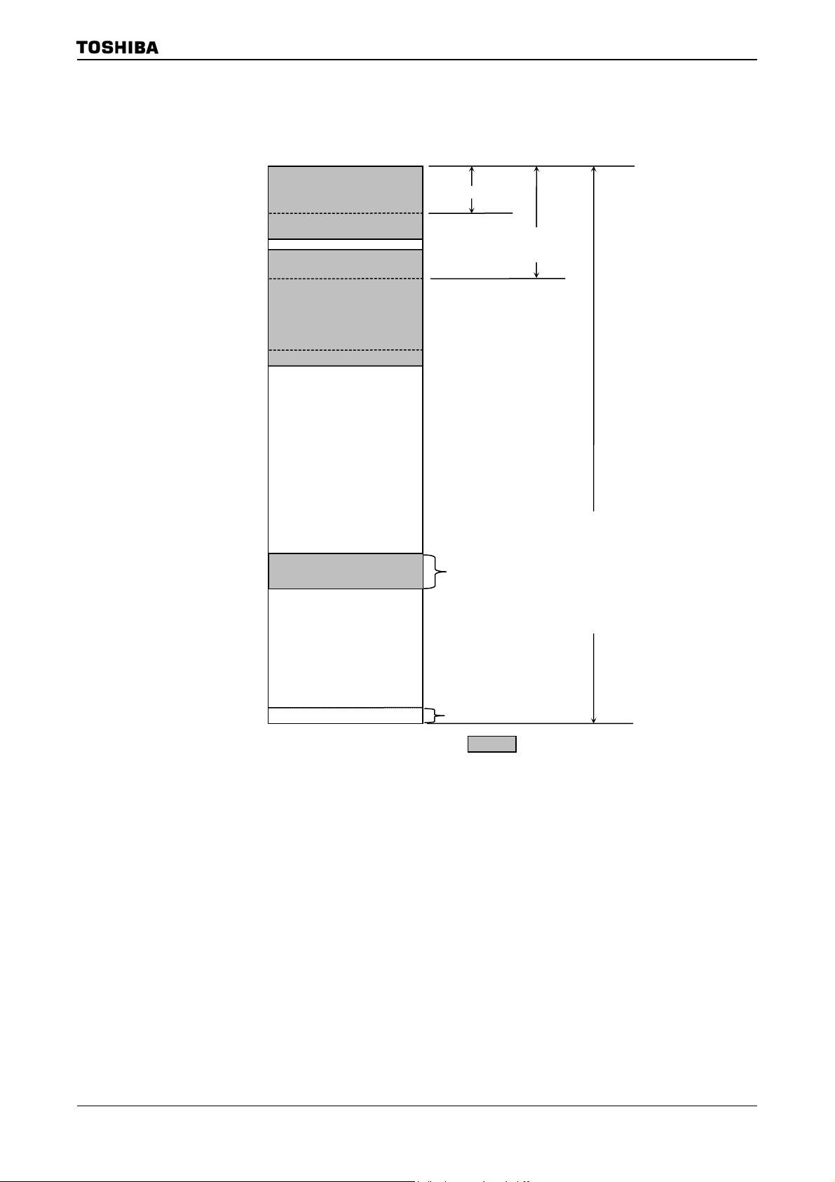
3.2 Memory Map
Figure 3.2.1 is a memory map of the TMP92CZ26A.
000000H
000100H
001FF0H
002000H
010000H
046000H
04A000H
F00000H
F10000H
FFFF00H
FFFFFFH
Internal I/O
(8 Kbyte)
Internal RAM
(288 Kbyte)
(Internal Back Up RAM 16kbyte)
External memory
Provisional Emulator Control Area
(64kbyte)
External memory
Vector table (256 Byte)
Direct area(n)
64Kbyte area
(nn)
16Mbyte area
(R)
(
(Note1)
(R
(R
(R + d8/16)
(nnn)
( = Internal area)
TMP92CZ26A
−R)
+)
+ R8/16)
Figure 3.2.1 Memory Map
Note1: Don’t use specified 64kbyte area of above 16M byte when using debug mode. This is because the area is reserved
for control in the debug mode.
Note2: Don’t use the last 16-byte area (FFFFF0H to FFFFFFH). This area is reserved as internal area.
92CZ26A-19
Page 23

3.3 Clock Function and Standby Function
TMP92CZ26A contains (1) clock gear, (2) clock doubler (PLL), (3) standby controller and (4)
noise-reducing circuit. They are used for low-power, low-noise systems.
This chapter is organized as follows:
3.3.1 Block diagram of system clock
3.3.2 SFRs
3.3.3 System clock controller
3.3.4 Prescaler clock controller
3.3.5 Noise-reducing circuit
3.3.7 Standby controller
TMP92CZ26A
92CZ26A-20
Page 24
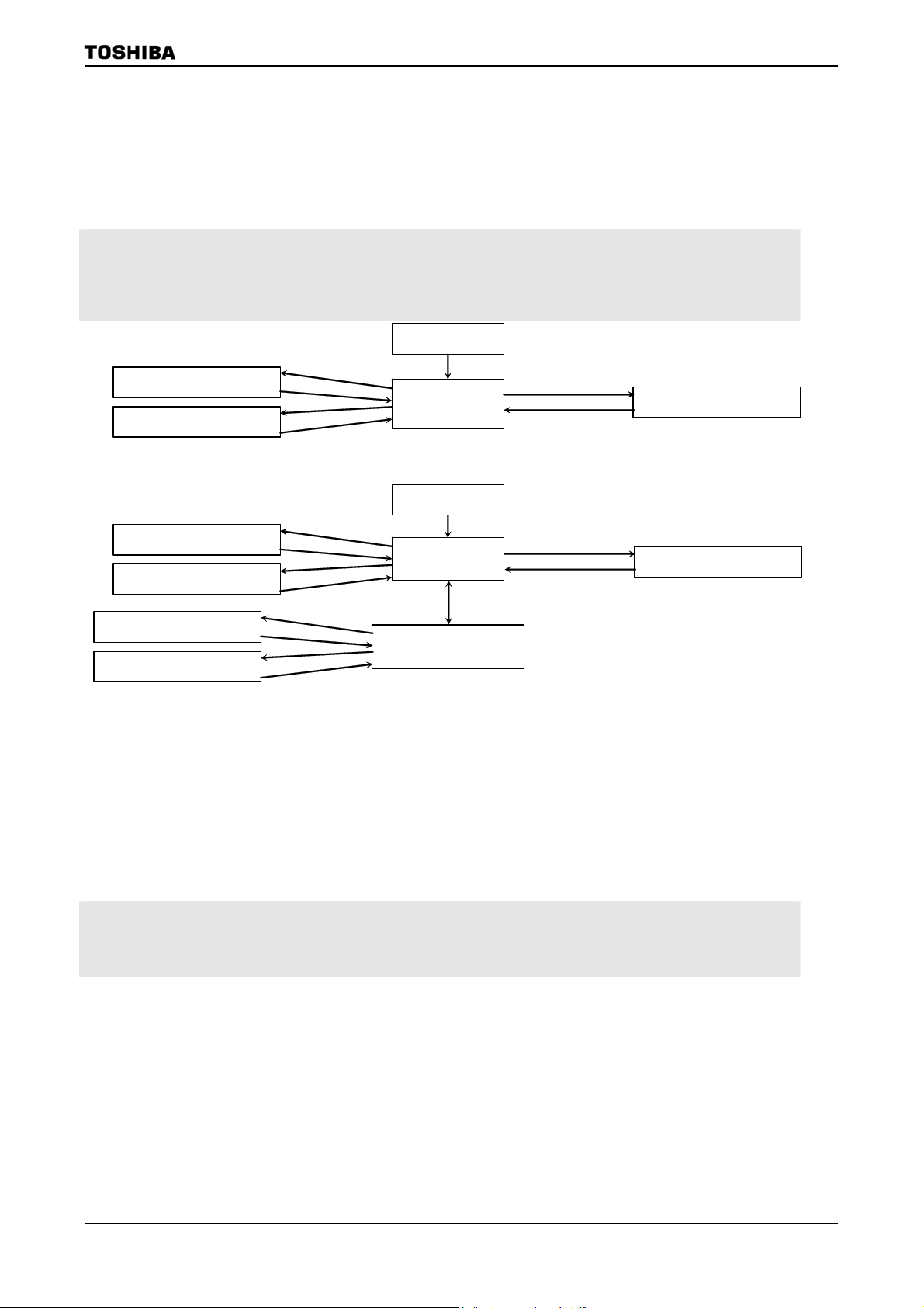
The clock operating modes are as follows: (a) PLL-OFF Mode (X1, X2 pins only),
(b) PLL-ON Mode (X1, X2, and PLL).
Figure 3.3.1 shows a transition figure.
The clock frequency input from the X1 and X2 pins is called fOSCH and the clock
frequency input from the XT1 and XT2 pins is called fs. The clock frequency selected by
SYSCR1<GEAR2:0> is called the system clock fSYS. And one cycle of fSYS is defined to
as one state.
IDLE2 mode
(I/O operate)
IDLE1 mode
(Operate only oscillator)
IDLE2 mode
(I/O operate)
IDLE1 mode
(Operate only oscillator)
IDLE2 mode
(I/O operate)
IDLE1 mode
(Operate only oscillator)
instruction
interrupt
instruction
interrupt
instruction
interrupt
instruction
interrupt
instruction
interrupt
instruction
interrupt
Reset
(f
/16)
OSCH
release Reset
PLL-OFF mode
/gear value)
(f
(a) PLL-OFF mode transition figure
OSCH
(f
PLL-OFF mode
(f
OSCH
PLL-ON mode
((12 or 16)×f
Reset
/16)
OSCH
release Reset
/gear value)
Instruction (Note)
/gear value)
OSCH
instruction
interrupt
instruction
interrupt
TMP92CZ26A
STOP mode
(Stops all circuits)
STOP mode
(Stops all circuits)
(b) PLL-OFF , PLL-ON mode transition figure
Note 1: If you shift from PLL-ON mode to PLL-OFF mode, execute following setting in the same order.
(1) Change CPU clock (Set “0” to PLLCR0<FCSEL>)
(2) Stop PLL circuit (Set “0” to PLLCR1<PLLON>)
Note 2: It’s prohibited to shift from PLL-ON mode to STOP mode directly.
You should set PLL-OFF mode once, and then shift to STOP mode.
Figure 3.3.1 System clock block diagram
The clock frequency input from the X1 and X2 pins is called f
called fs. The clock frequency selected by SYSCR1<GEAR2:0> is called the sy stem clock f
to as one state.
and the clock frequency input from the XT1 and XT2 pins is
OSCH
. And one cycle of f
SYS
is defined
SYS
92CZ26A-21
Page 25

R
r
r
(
3.3.1 Block diagram of system clock
SYSCR0<WUEF>
SYSCR2<WUPTM1:0>
TMP92CZ26A
SYSCR0<XTEN >
XT1
XT2
X1
X2
X1USB
Low frequency
Oscillator circuit
High frequency
Oscillator circuit
φT0TMR
Warming up timer
(High/Low frequency oscillator circuit)
Lock up timer
(PLL)
PLLCR1<PLLON>,
fs
Clock Doubler0
×
f
OSCH
PLLCR0<LUPFG>
(PLL0)
12 or16)
÷2
f
PLL
PLLCR0<FCSEL>
Clock Doubler1
(PLL1)× 24
f
SYS
f
io
TMRA0:7,TMRB0:1
Prescaler
SIO0
φT0
Prescaler
SBI
Prescaler
fc
fc/2
÷2 ÷16÷4
÷5
fc/4
fc/8
÷8
Clock gear
f
PLLUSB
÷2
÷8
SYSCR0<PRCK>
fc/16
SYSCR1<GEAR2:0>
SYSCR0<USBCLK1:0>
CPU
RAM
Interrupt
NAND-Flash
Controller
I/O ports
SDRAMC
DMAC
÷4
LCDC
Memory
Controlle
Controlle
2
S
I
TSI
SPIC
÷2
÷2
φT0
φT0TM
fs
f
SYS
fIO
f
USB
f
OSCH4
RTC
MAC
fs
MLD/ALM
ADC
f
USB
USB
Figure 3.3.2 Block Diagram of System clock
92CZ26A-22
Page 26
TMP92CZ26A
TMP92CZ26A has two PLL circuits: one is for CPU (PLL0) and the other for USB (PLL1).
Each PLL can be controlled independently. Frequency of external oscillator is 6 to 10MHz.
Don’t connect oscillator m ore than 10 MH z. When clo ck is in put by usin g ext ern al osci llato r,
range of input frequency is 6 to10MHz. Don’t input the clock over 10MHz.
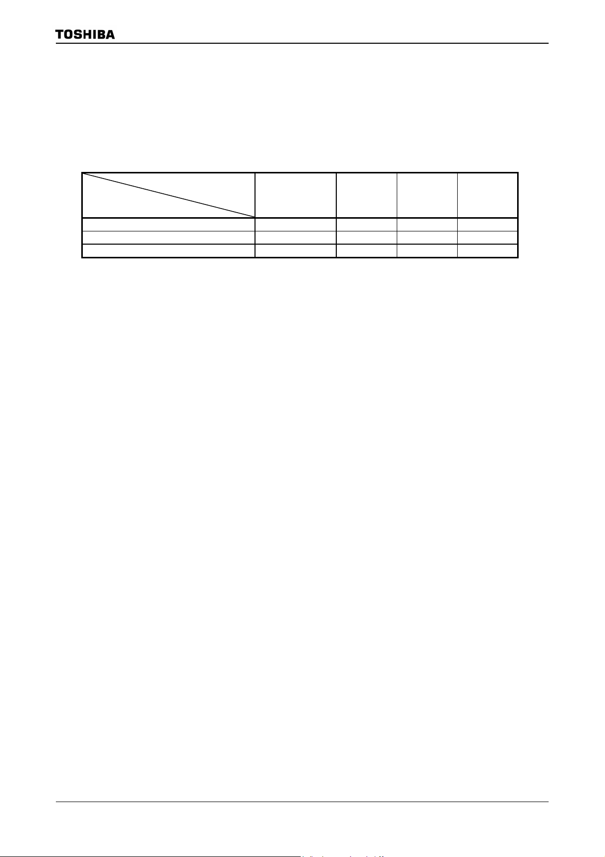
Table 3.3.1 Setting example for f
(a) PLL, USB (PLL0 ON/PLL1ON) 10.0 MHz Max 80 MHz Max 60 MHz 48 MHz
(b) PLL, No USB (PLL0 ON/PLL1OFF) Max 10.0 MHz Max 80 MHz Max 60 MHz
(c) No PLL, No USB (PLL0 OFF/PLL1OFF) Max 10.0 MHz Max 10 MHz Max 10 MHz
Note: When using USB, set high-frequency oscillator to 10.0 MHz.
High frequency:
f
OSCH
System
clock:
f
OSCH
SYS
System
clock:
f
SYS
USB
clock:
f
USB
−
−
92CZ26A-23
Page 27
3.3.2 SFR
SYSCR0
(10E0H)
SYSCR1
(10E1H)
SYSCR2
(10E2H)
TMP92CZ26A
7 6 5 4 3 2 1 0
bit Symbol XTEN
USBCLK1 USBCLK0
Read/write R/W R/W R/W R/W R/W
After Reset 1 0 0 0 0
Select the clock of
USB(f
)
USB
00:Disable
01: Reserved
10:X1USB
11:f
PLLUSB
Function
Low
-frequency
oscillator
circuit (fs)
0: Stop
1: Oscillation
WUEF PRCK
Warm-up
Timer
0: Write
Don’t care
Note3
1: Write
start timer
0: Read
end
warm-up
1: Read
do not end
warm-up
Select
Prescaler
clock
0: f
SYS
1: f
SYS
/2
/8
7 6 5 4 3 2 1 0
bit Symbol GEAR2 GEAR1 GEAR0
Read/write R/W
After Reset 1 0 0
Function
Select gear value of high frequency (fc)
000: fc
001: fc/2
010: fc/4
011: fc/8
100: fc/16
101: Reserved
110: Reserved
111: Reserved
7 6 5 4 3 2 1 0
bit Symbol
–
Read/write R/W R/W R/W R/W R/W R/W
After Reset 0 0 1 0 1 1
Always
write “0”
Function
Note1: SYSCR0<bit7><bit3><bit1>,SYSCR1<bit7:3> and SYSCR2<bit1:0> are read as undefined value.
Note2: By reset, low frequency oscillator circuit is enabled.
Note3: Don’t write SYSCR0 resiter during warming up. Because the warm-up end flag doesn’t become enable if
write ”0” to SYSCR0<WUEF> bit during warming up.
( Read-modify-write is prohibited for SYSCR0 register during warming up.)
CKOSEL WUPTM1 WUPTM0 HALTM1 HALTM0
Select
CLKOUT
0: f
SYS
1: fS
Warm-Up Timer
00: reserved
8
01: 2
/inputted frequency
14
10:2
/inputted frequency
16
11:2
/inputted frequency
HALT mode
00: Reserved
01: STOP mode
10: IDLE1 mode
11: IDLE2 mode
Figure 3.3.3 SFR for system clock
92CZ26A-24
Page 28
EMCCR0
(10E3H)
EMCCR1
(10E4H)
EMCCR2
(10E5H)
TMP92CZ26A
7 6 5 4 3 2 1 0
Bit symbol
Read/Write R R/W R/W R/W R/W
After reset 0 0 0 1 1
Function
Bit symbol
Read/Write
After reset
Function
Bit symbol
Read/Write
After reset
Function
Note: In case restarting the oscillator in the stop oscillation state (e.g. Restart the oscillator in STOP mode), set
PROTECT
Protect flag
0: OFF
1: ON
EMCCR0<DRVOSCH>, <DRVOSCL>
Switching the protect ON/OFF by write to following 1
st
1
-KEY: EMCCR1=5AH,EMCCR2=A5H in succession write
nd
2
-KEY: EMCCR1=A5H,EMCCR2=5AH in succession write
=”1”.
−
Always
write “0”.
EXTIN DRVOSCH DRVOSCL
1: External
clock
st
-KEY,2nd-KEY
fc oscillator
drive ability
1: NORMAL
0: WEAK
fs oscillator
drive ability
1: NORMAL
0: WEAK
Figure 3.3.4 SFR for system clock
92CZ26A-25
Page 29
PLLCR0
(10E8H)
PLLCR1
(10E9H)
TMP92CZ26A
7 6 5 4 3 2 1 0
bit symbol FCSEL LUPFG
Read/Write R/W R
After reset 0 0
Function
Note: Be carefull that logic of PLLCR0<LUPFG> is different from 900/L1’s DFM.
Select
fc-clock
0 : f
OSCH
1 : f
PLL
Lock-up
timer
Status flag
0 : not end
1 : end
7 6 5 4 3 2 1 0
bit symbol PLL0 PLL1 LUPSEL
Read/Write R/W R/W R/W R/W
After reset 0 0 0 0
Select the
Function
PLL0 for
CPU
0: Off
1: On
PLL1 for
USB
0: Off
1: On
Select
stage of
Lock up
counter
0: 12 stage
(for PLL0)
1:13 stage
(for PLL1)
PLLTIMES
number of
PLL
0: ×12
1: ×16
PxDR
(xxxxH)
Figure 3.3.5 SFR for PLL
7 6 5 4 3 2 1 0
bit symbol Px7D Px6D Px5D Px4D Px3D Px2D Px1D Px0D
Read/Write R/W
After reset 1 1 1 1 1 1 1 1
Function Output/Input buffer drive-register for standby-mode
(Purpose and method of using)
• This register is used to set each pin-status at stand-by mode.
• All ports have this format’s register. (“x” means port-name.)
• For each register, refer to 3.5 Function of Ports.
• Before “HALT” instruction is executed, set each register pin-status. They will be
effective after CPU executes “HALT” instructi on.
• This register is effective in all stand-by modes (IDLE2, IDLE1 or STOP).
• This register is effective when using PMC function. For details, refer to PMC
section.
The truth table to control Output/Input-buffer is below.
OE PxnD Output buffer Input buffer
0 0 OFF OFF
0 1 OFF ON
1 0 OFF OFF
1 1 ON OFF
Note1: OE means an output enable signal before stand-by mode. Basically, PxCR is used as OE.
Note2: “n” in PxnD means bit-number of PORTx.
Figure 3.3.6 SFR for drive register
92CZ26A-26
Page 30

3.3.3 System clock controller
TMP92CZ26A
The system clock controller generates the system clock signal (f
) for the CPU core and
SYS
internal I/O.
SYSCR0<XEN> and SYSCR0<XTEN> control enabling and disabling of each oscillator.
SYSCR1<GEAR2:0> sets the high frequency clock gear to either 1, 2, 4, 8 or 16 (fc, fc/2, fc/4,
fc/8, fc/16). These functions can reduce the power consumption of the equipment in which
the device is installed.
The combination of settings <XEN> = “1”, <SYSCK> = “0” and <GEAR2 to 0> = “100” will
be PLL-OFF mode and cause the system clock (f
For example, f
is set to 625 kHz when the 10MHz oscillator is conn ected to the X1 an d
SYS
) to be set to fc/16 after reset.
SYS
X2 pins.
(1) Clock gear controller
is set according to the contents of the Clock Gear Select Register SYSCR1<GEAR2:
f
SYS
0> to either fc, fc/2, fc/4, fc/8 or fc/16. Using the clock gear to select a lower value of f
SYS
reduces power consumption.
(Example)
Changing clock gear
SYSCR1 EQU 10E1H
LD (SYSCR1),XXXXX001B ; Changes system clock f
LD (DUMMY),00H Dummy instruction
X: don't care
SYS to
fc/2
(High-speed clock gear changing)
To change the clock gear, write the register value to the SYSCR1<GEAR2 to 0> register.
It is necessary the warming up time until changing after writ ing the register value.
There is the possibility that the instruction next to the cl ock gea r changing i n struction is
executed by the clock gear before changing. To execu te the instruction next to the cl ock gear
switching instruction by the clock gear after changing, input the dummy instruction as
follows (instruction to execute the write cycle).
(Example)
SYSCR1 EQU 10E1H
LD (SYSCR1),XXXXX010B ; Changes f
LD (DUMMY),00H ; Dummy instruction
Instruction to be executed after clock gear changed
SYS
to fc/4
92CZ26A-27
Page 31

3.3.4 Clock doubler (PLL)
TMP92CZ26A
PLL0 outputs the f
clock signal, which is 12 or 16 times as fast as f
PLL
. That is, the
OSCH
low-speed frequency oscillator can be used as external oscillator, even though the internal
clock is high-frequency.
Since Reset initializes PLL0 to stop status, setting to PLLCR0 and PLLCR1-register is
needed before use.
Like an oscillator, this circuit require s time to stabilize. This is called the lock-up time
and it is measured by 12-stage binary counter. Lock-up time is about 0.41ms at f
OSCH
=
10MHz.
PLL (PLL1) which is special for USB is build in. Lock-up time is about 0.82ms at f
OSCH
=
10MHz measured by 13-stage binary counter.
Note1: Input frequency limitation for PLL
The limitation of input frequency (High frequency oscillation) for PLL is following.
= X to X MHz (Vcc = 1.4 to 1.6V)
f
OSCH
Note2: PLLCR0<LUPFG>
The logic of PLLCR0<LUPFG> is different from 900/L1’s DFM.
Be careful to judge an end of lock-up time.
Note3: PLLCR1<PLL0>, PLLCR1<PLL1>
It’s prohibited to turn ON both PLL0 and PLL1 simultaneously.
If turning ON simultaneously, one PLL should be turn ON after finishing the lock up of the other PLL.
Figure 3.3.7 shows the frequency of f
when using PLL and clock gear at f
SYS
OSCH
=10MHz.
f
f
OSH
10MHz
×12 120MHz 60MHz 30MHz 15MHz 7.5MHz 3.75MHz
×16 160MHz 80MHz 40MHz 20MHz 10MHz 5MHz
PLL
f
10MHz 10MHz 5MHz 2.5MHz 1.25MHz 625KHz
OSH
fc fc/2 fc/4 fc/8 fc/16
Frequency of f
SYS
Figure 3.3.7 The frequency of f
SYS
at f
=10MHz
OSH
92CZ26A-28
Page 32

A
TMP92CZ26A
The following is a setting example for PLL0-starting and PLL0-stopping.
(Example-1) PLL0-starting
PLLCR0 EQU 10E8H
PLLCR1 EQU 10E9H
LD (PLLCR1),1XXXXXXXXB ;
LUP: BIT 5,(PLLCR0) ;
JR Z,LUP ;
LD (PLLCR0), X1XXXXXXB ; Changes fc from 10 MHz to 60 MHz.
X: Don't care
<PLL0>
<FCSEL>
PLL output: f
PLL
Enables PLL0 operation and starts lock-up
Detects end of lock-up
.
Lockup timer
<LUPFG>
System clock f
SYS
Counts up by f
Starts PLL0 operation and
Starts lock-up.
OSCH
During lock-up
fter lock-up
Changes from 10MHz to 60MHz.
Ends of lock-up
(Example-2) PLL0-stopping
PLLCR0 EQU 10E8H
PLLCR1 EQU 10E9H
LD (PLLCR0),X0XXXXXXB ; Changes fc from 60 MHz to10 MHz.
LD (PLLCR1),0XXXXXXXB ; Stop PLL
X: Don't care
<FCSEL>
<PLL0>
PLL0 output: f
System clock f
PLL
SYS
Changes from 60MHz to 10 MHz.
Stops PLL0 operation .
Note) PLL1 operates as well.
92CZ26A-29
Page 33

TMP92CZ26A
Limitation point on the use of PLL0
1. If you stop PLL operation during using PLL0, you should execute following setting in
the same order.
LD (PLLCR0),X0XXXXXXB ;
LD (PLLCR1),0XXXXXXXB ; Stop PLL0
X: Don't care
Change the clock f
PLL
to f
OSCH
2. If you shift to STOP mode during using PLL, you should execute following setting in the
same order.
LD (SYSCR2), XXXX01XXB ;
LD (PLLCR0), X0XXXXXXB ;
LD (PLLCR1), 0XXXXXXXB ; Stop PLL0
HALT ; Shift to STOP mode
X: Don't care
Set the STOP mode
Change the system clock f
PLL
to f
OSCH
Examples of settings are below;
(1) Start Up / Change Control
(OK) High frequency oscillator operati on m ode(f
→ PLL0 use mode (f
LD (PLLCR1), 1XXXXXXXB ; PLL0 start up / lock up start
LUP: BIT 5,(PLLCR0) ;
JR Z,LUP ; Check for the flag of lock up end
LD (PLLCR0), X1XXXXXXB ; Change the system clock fOSCH to fPLL
X: Don't care
PLL
)
)→PLL0 start up
OSCH
(2) Change / Stop Control
(OK) PLL0 use mode (f
)→ High frequency oscillator operation mode(f
PLL
OSCH
)
→ PLL0 Stop
LD (PLLCR0),X0XXXXXXB ; Change the system clock fPLL to fOSCH
LD (PLLCR1),0XXXXXXXB ; Stop PLL0
X: Don't care
(OK) PLL0 use mode (f
→High frequency oscillator operation mode (f
) → Set the STOP mode
PLL
) → PLL stop
OSCH
→ HALT(High frequency oscillator stop)
LD (SYSCR2),XXXX01XXB ; Set the STOP mode
(This command can be executed before use of PLL0)
LD (PLLCR0),X0XXXXXXB ;
LD (PLLCR1),0XXXXXXXB ; Stop PLL0
HALT ; Shift to STOP mode
X: Don't care
Change the system clock f
PLL
to f
OSCH
(NG) PLL0 use mode (f
) → Set the STOP mode
PLL
→ HALT(High frequency oscillator stop)
LD (SYSCR2),XXXX01XXB ; Set the STOP mode
(This command can be executed before use of PLL0)
HALT ; Shift to STOP mode
X: Don't care
92CZ26A-30
Page 34

3.3.5 Noise reduction circuits
Noise reduction circuits are built in, allowing implementation of the following features.
(1) Reduced drivability for high-frequency oscillator circuit
(2) Reduced drivability for low-frequency osci llator circuit
(3) Single drive for high-frequency oscillator circuit
(4) SFR protection of register contents
These are set in EMCCR0 to EMCCR2 registers.
(1) Reduced drivability for high-frequency oscillator circuit
(Purpose)
Reduces noise and power for oscillator when a reson ator is used.
(Clock diagram)
C1
X1 pin
f
OSCH
Enable oscillation
TMP92CZ26A
resonator
C2
X2 pin
EMCCR0<DRVOSCH>
(Setting method)
The drivability of the oscillator is reduced by writing”0” to EMCCR0<DRVOSCH>
register . By reset, <DR VOSCH> is initializ ed to “1” and the oscillator starts oscillat ion
by normal-drivability when the power-supply is on.
Note: This function (EMCCR0<DRVODCH>= “0”) is available to use in case f
= 6 to 10MHz condition.
OSCH
92CZ26A-31
Page 35

TMP92CZ26A
(2) Reduced drivability for low-freq uency oscillator circuit
(Purpose)
Reduces noise and power for oscillator when a reson ator is used.
(Block diagram)
C1
XT1 pin
Enable oscillation
Resonator
C2
XT2 pin
EMCCR0<DRVOSCL>
f
S
(Setting method)
The drivability of the oscillator is reduc ed by writing 0 to the EM CCR0<DR VOSCL>
register. By Reset, <DRVOSCL> is initialized to “1 ”.
(3) Single drive for high-frequenc y oscillator circuit
(Purpose)
Not need twin-drive and protect mistake-operat ion by inputted noise to X2 pin when
the external-oscillator is used
.
(Block diagram)
f
X1 pin
Enable oscillation
OSCH
EMCCR0<DRVOSCH>
X2 pin
(Setting method)
The oscillator is disabled and starts operation as buffer by writing “1” to
EMCCR0<EXTIN> register. X2-pin is always outputted”1”.
By reset,<EXTIN> is initialized to “0”.
Note: Do not write EMCCR0<EXTIN> = “1” when using external resonator.
92CZ26A-32
Page 36

TMP92CZ26A
(4) Runaway provision with SFR protection register
(Purpose)
Provision in runaway of program by noise mixing.
Write operation to speci fied SFR is prohibited so that provision program in runaway
prevents that it is in the state which is fetch impossibility by stopping of clock,
memory control register (Memory controller, MMU) is changed.
And error handling in runaway becomes easy by INTP0 interruption.
Specified SFR list
1. Memory controller
B0CSL/H, B1CSL/H, B2CSL/H, B3CSL/H, BECSL/H
MSAR0, MSAR1, MSAR2, MSAR3,
MAMR0, MAMR1, MAMR2, MAMR3, PMEMCR,
MEMCR0, CSTMGCR, WRTMGCR, RDTMGCR0
RDTMGCR1, BROMCR
2. MMU
LOCALPX/PY/PZ, LOCALLX/LY/LZ,
LOCALRX/RY/RZ, LOCALWX/WY/WZ,
LOCALESX/ESY/ESZ, LOCALEDX/EDY/EDZ,
LOCALOSX/OSY/OSZ, LOCALODX/ODY/ODZ
3. Clock gear
SYSCR0, SYSCR1, SYSCR2, EMCCR0
4. PLL
PLLCR0,PLLCR1
5. PMC
PMCCTL
(Operation explanation)
Execute and release of protection (write operation to specified SFR) becomes
possible by setting up a double key to EMCCR1 and EMCCR2 register.
(Double key)
st
-KEY: Succession writes in 5AH at EMCCR1 and A5H at EMCCR2
1
nd
-KEY: Succession writes in A5H at EMCCR1 and 5AH at EMCCR2
2
A state of pr otection can be confirmed by reading EMCCR0<PROTECT>.
By reset, protection becomes OFF.
And INTP0 interruption occurs when write operation to specified SFR was execu ted
with protection on state.
92CZ26A-33
Page 37

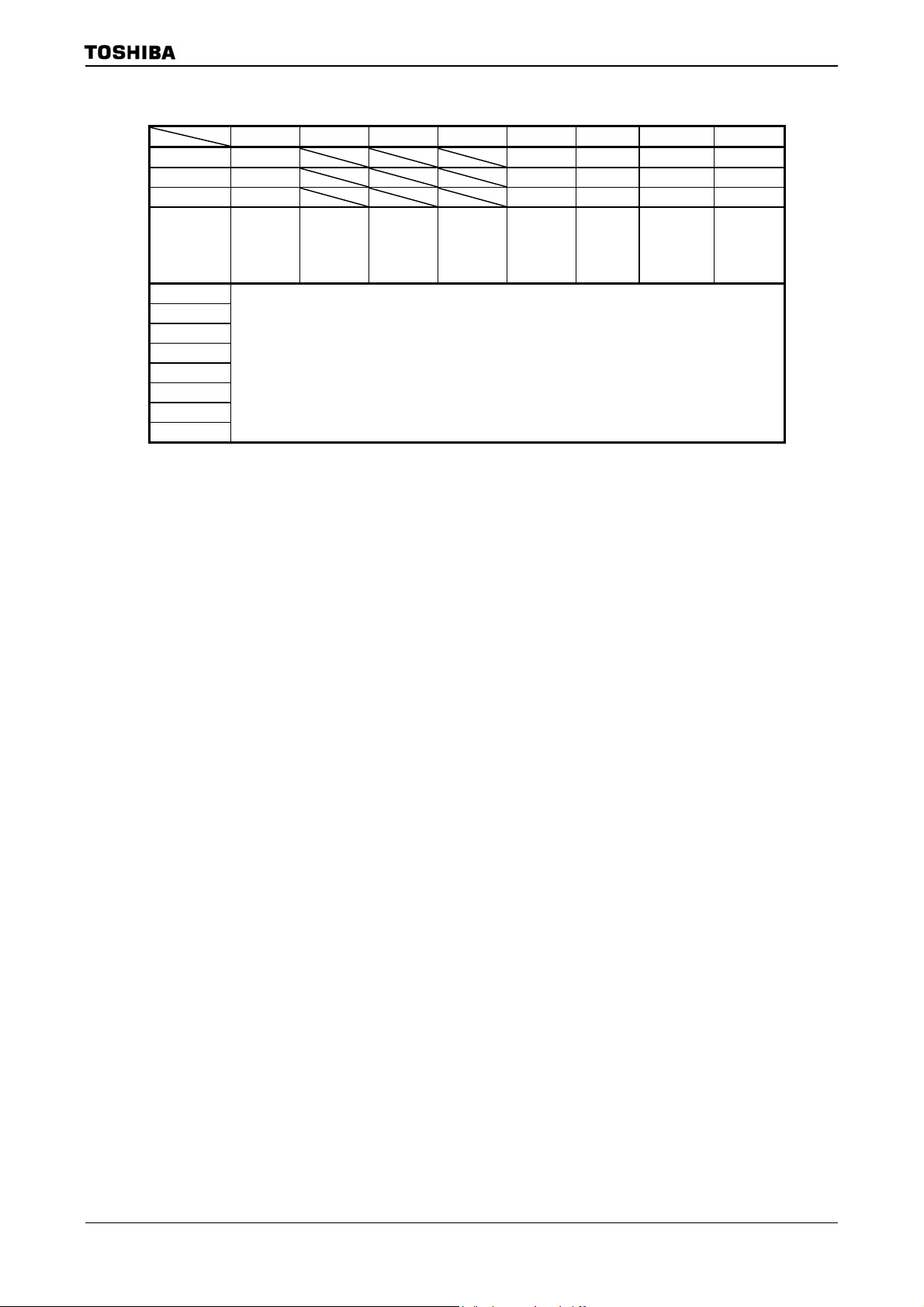
3.3.6 Standby controller
(1) Halt Modes and Port Drive-register
When the HALT instruction is executed, the operating mode switches to IDLE2,
IDLE1 or STOP Mode, depending on the contents of the SYSCR2<HALTM1 to 0>
register and each pin-status is set according to PxDR-register.
7 6 5 4 3 2 1 0
PxDR
(xxxxH)
bit symbol Px7D Px6D Px5D Px4D Px3D Px2D Px1D Px0D
Read/Write R/W
After reset 1 1 1 1 1 1 1 1
Function Output/Input buffer drive-register for standby-mode
(Purpose and method of using)
• This register is used to set each pin-status at stand-by mode.
• All ports have this format’s register. (“x” means port-name.)
• For each register, refer to 3.5 Function of Ports.
• Before “HALT” instruction is executed, set each register pin-status. They will be
effective after CPU executes “HALT” instructi on.
• This register is effective in all stand-by modes (IDLE2, IDLE1 or STOP).
• This register is effective when using PMC function. For details, refer to PMC
section.
The truth table to control Output/Input-buffer is below.
Note1: OE means an output enable signal before stand-by mode.Basically, PxCR is used as OE.
Note2: “n” in PxnD means bit-number of PORTx.
The subsequent actions performed in each mode are as follows:
TMP92CZ26A
OE PxnD Output buffer Input buffer
0 0 OFF OFF
0 1 OFF ON
1 0 OFF OFF
1 1 ON OFF
a. IDLE2: Only the CPU halts.
The internal I/O is available to select operation during IDLE2 mode by
setting the following register.
Tabl e 3. 3. 2 shows the registers of setting operation during IDLE2 mode.
Table 3.3.2 SFR setting operation during IDLE2 mode
Internal I/O SFR
TMRA01 TA01RUN<I2TA01>
TMRA23 TA23RUN<I2TA23>
TMRA45 TA45RUN<I2TA45>
TMRA67 TA67RUN<I2TA67>
TMRB0 TB0RUN<I2TB0>
TMRB1 TB1RUN<I2TB1>
SIO0 SC0MOD1<I2S0>
SBI SBIBR0<I2SBI>
A/D converter ADMOD1<I2AD>
WDT WDMOD<I2WDT>
b. IDLE1: Only the oscillator, RTC (real-time clock), and MLD continue to
operate.
c. STOP: All internal circuits stop operating.
92CZ26A-34
Page 38

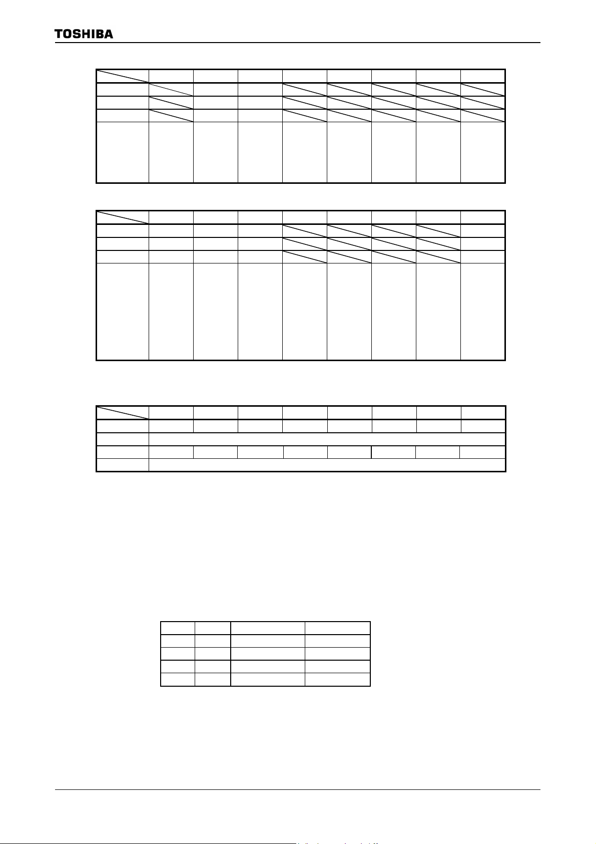
TMP92CZ26A
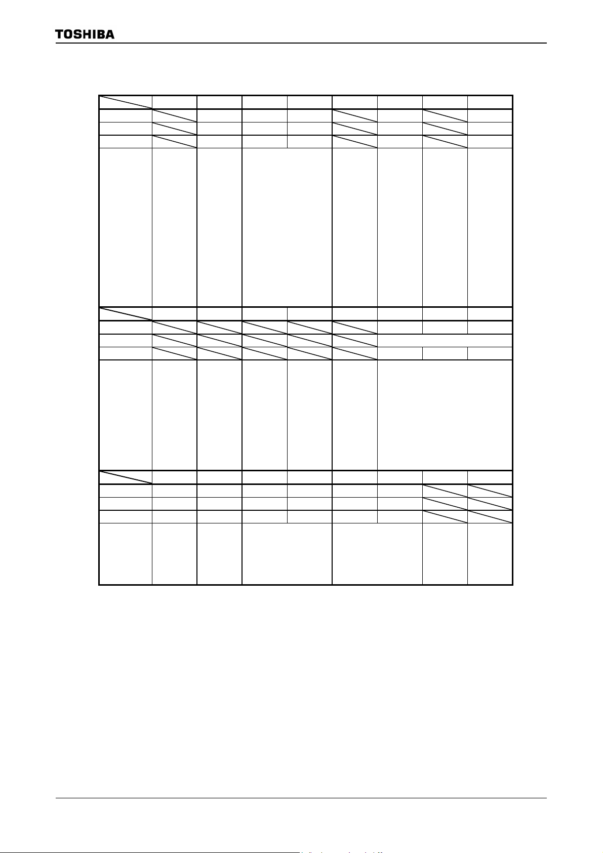
The operation of each of the different Halt Modes is described in
Table 3.3.3 .
Table 3.3.3 I/O operation during Halt Modes
Halt Mode IDLE2 IDLE1 STOP
SYSCR2 <HAL TM1:0 > 1 1 10 01
CPU, MAC Stop
I/O ports Depends on PxDR register setting
TMRA, TMRB
SIO,SBI
A/D converter
Block
WDT
I2S, LCDC, SDRAMC,
Interrupt controller,
SPIC, DMAC, NDFC,
USB
RTC, MLD
Available to select
Operation block
Stop
Operate
Operate
(2) How to release the Halt mode
These HALT states can be released by resetting or requesting an interru pt. The halt
release sources are determined by the combination between the states of interrupt
mask register <IFF2:0> and the halt modes. The details for releasing the HALT status
are shown in
Table 3.3.4.
• Released by requesting an interrupt
The operating released from the halt mode depends on th e interrupt enab led status.
When the interrupt request level set before executing the HALT instruction exceeds
the value of interrupt mask register, the interrupt due to the source is processed after
releasing the halt mode, and CPU status executing an instruction that follows the
HALT instruction. When the interrupt request level set before executing the HALT
instruction is less than the value of the interrupt mask register, releasing the halt
mode is not executed.(in non-maskable interrupts, interrupt processing is processed
after releasing the halt mode regardless of the value of the mask register.) However
only for INT0 to INT5, INT6, INT7(unsynchronous interrupt), INTKEY,INTRTC,
INTALM int errupts, ev en if th e int errupt requ est level s et befor e executi ng the H ALT
instruction is less than the value of the interrupt mask register, releasing the halt
mode is executed. In this case, interrupt processing, and CPU starts executing the
instruction next to the HALT instruction, but the interrupt request flag is held at “1”.
• Releasing by resetting
Releasing all halt status is executed by resetting.
When the STOP mode is released by RESET, it is necessary enough resetting time to
set the operation of the oscillator to be stabl e.
When releasing the halt mode by resetting, the internal RAM data keeps the state
before the “HALT” instruction is executed. However the other settings contents are
initialized. (Releasing due to interrup ts keeps the state b efore t he “HALT” instruction
is executed.)
92CZ26A-35
Page 39

Table 3.3.4 Source of Halt state clearance and Halt clearance operation
Status of Received Interrupt
Halt mode IDLE2 IDLE1 STOP IDLE2 IDLE1 STOP
INTWDT
INT0 to 5 (Note1)
INTKEY
INTUSB
INT6 to 7(PORT) (Note1)
INT6 to 7(TMRB)
INTALM, INTRTC
INTTA0 to 7, INTTP0
Interrupt
INTTB00 to 01, INTTB10 to 11
INTRX,INTTX, INTSBI
INTI2S0 to 1, INTLCD,
INTAD, INTADHP
Source of Halt state clearance
INTSPIRX,INTSPITX
INTRSC, INTRDY
INTDMA0 to 5
RESET Reset initializes the LSI
: After clearing the Halt mode, CPU starts interrupt processing.
{: After clearing the Halt mode, CPU resumes executing starting from instruction following the HALT instruction.
×: It can not be used to release the halt mode.
−: The priority level (interrupt request level) of non-maskable interrupts is fixed to 7, the highest priority level. There is
not this combination type.
*1: Releasing the halt mode is executed after passing the warmming-up time.
*2: 6 interrupts of all 24 INTUSB sources can release Halt state from IDLE1 mode. Therefore, the system of low
power dissipation can be built. However, the way of use is limited as below.
• Shift to IDLE1 mode :
Execute Halt instruction when the flag of INT_SUS or INT_CLKSTOP is “1” ( SUSPEND state )
• Release from IDLE1 mode :
Release Halt state by the request of INT_RESUME or INT_CLKON ( request of release SUSPEND )
Release Halt state by the request of INT_URST_STR or INT_URST_END ( request of RESET )
Note1: When the Halt mode is cleared by an INT0 interrupt of the level mode in the interrupt enabled status, hold level
H until starting interrupt processing. If level L is set before holding level L, interrupt processing is correctly
started.
TMP92CZ26A
Interrupt Enabled
(interrupt level) ≥ (interrupt mask)
× × − − −
× × × × ×
× { { ×
*2
× { {*2 ×
× × × × ×
(interrupt level) < (interrupt mask)
*1
{ { {*1
*1
{ { {*1
Interrupt Disabled
92CZ26A-36
Page 40

TMP92CZ26A
(Example - releasing IDLE1 Mode)
An INT0 interrupt clears the Halt state when the device is in IDLE1 Mode.
Address
8200H LD (PCFC), 02H ; Sets PC1 to INT0 interrupt.
8203H LD (IIMC0), 00H ; Select INT0 interrupt rising edge.
8206H LD (INTE0), 06H ; Sets INT0 interrupt level to 6.
8209H EI 5 ; Sets CPU interrupt level to 5.
820BH LD (SYSCR2), 28H ; Sets Halt mode to IDLE1 mode.
820EH HALT ; Halts CPU.
INT0 INT0 interrupt routine.
RETI
820FH LD XX, XX
92CZ26A-37
Page 41

r
r
(3) Operation
Interrupt fo
releasing Halt
TMP92CZ26A
a. IDLE2 Mode
In IDLE2 Mode, only specific internal I/O operations, as designated by the
IDLE2 Setting Register, can take place. Instruction execution by the CPU stops.
Figure 3.3.8 illustrates an example of the timing for clearance of the IDLE2
Mode Halt state by an interrupt.
X1
A0~A23
D0~D31
RD
WR
Data
IDLE2
mode
Data
Figure 3.3.8 Timing chart for IDLE2 Mode Halt state cleared by interrupt
b. IDLE1 Mode
In IDLE1 Mode, only the internal oscillator and the RTC and MLD continue to
operate. The system clock stops.
In the Halt state, the interrupt request is sampled asynchronously with the
system clock; however, clearance of the Halt state (i.e. restart of operation) is
synchronous with it.
Figure 3.3.9 illustrates the timing for clearance of the IDLE1 Mode Halt state b y
an interrupt.
X1
A0~A23
D0~D31
RD
Data Data
releasing Halt
WR
Interrupt fo
IDLE1
mode
Figure 3.3.9 Timing chart for IDLE1 Mode Halt state cleared by interrupt
92CZ26A-38
Page 42

r
A0~A23
D0~D31
Interrupt fo
releasing Halt
TMP92CZ26A
c. STOP Mode
When STOP Mode is selected, all internal circuits stop, including the internal
oscillator.
After STOP Mode has been cleared system clock output starts when the warm-up
time has elapsed, in order to allow oscillation to stabiliz e.
Figure 3.3.10 illustrates the timing for clearance of the STOP Mode Halt state by a n
interrupt.
Warm-up
time
X1
Data
RD
STOP
mode
Data
Figure 3.3.10 Timing chart for STOP Mode Halt state cleared by interrupt
Table 3.3.5 Example of warming-up time after releasing STOP-mode
@f
OSCH
=10 MHz
SYSCR2<WUPTM1:0>
01 (28) 10 (214) 11 (216)
25.6 us 1.6384 ms 6.5536 ms
92CZ26A-39
Page 43

TMP92CZ26A
Table 3.3.6 Input Buffer State Table
Input Buffer State
Port Name
D0-D7 D0-D7 OFF − − −
P10-P17 D8-D15
P60-P67 −
P71-P74 − − − −
P75 NDR/W
P76 WAIT
P90 − − − −
P91 RXD0
P92
P96 *1 INT4
P97 − − − −
PA0-PA7 *1 KI0-7
PC0 INT0
PC1 INT1,TA0IN
PC2 INT2
PC3 INT3,TA2IN
PC4-PC7 −
PF0-PF5 −
PG0-PG2
PG4,PG5 *2
PG3 *2 ADTRG
PJ5-PJ6 −
PN0-PN7 −
PP1-PP2 −
PP3 INT5
PP4 INT6,TB0IN0
PP5 INT7,TB1IN0
PR0 SPDI
PR1-PR3 −
PT0-PT7 −
PU0-PU4,
PU6,PU7
PU5 −
PV0-PV2 −
PV6-PV7 SDA, SCL
PW0-PW7 −
PX5 X1USB
PX7 −
PZ0-PZ5
PZ6-PZ7 −
DBGE
D+, D-
RESET −
AM0,AM1 −
X1,XT1 − IDLE2/DLE1: ON
Input Function
Name
,SCLK0
0CTS
− − − −
−
EI_PODDATA,
EI_SYNCLK,
EI_PODREQ,
EI_REFCLK,
EI_TRGIN,
EI_COMRESET
−
−
ON: The buffer is always turned on. A current flows the input buffer if the input
pin is not driven.
OFF: The buffer is always turned off.
- : No applicable
During Reset
16bit Start OFF
Boot Start ON
16bit Start OFF
Boot Start ON
ON
OFF
ON
When the CPU is operating
When Used as
function Pin
ON upon
external read
− − −
ON ON OFF
ON ON OFF
ON ON OFF
−
ON
− − −
ON ON OFF
− − −
ON ON
−
When Used
as Input port
ON
ON upon port
read
ON
When Used
as function
Always ON
*1: Port having a pull-up/pull-down resistor.
*2: AIN input does not cause a current to flow through the buffer.
In HALT mode (IDLE2/1/STOP)
<PxDR>=1 <PxDR>=0
When Used
Pin
OFF OFF
−
ON
−
as Input port
ON
OFF
ON
When Used
as function
Pin
−
ON
OFF
ON
−
When Used
as Input port
OFF
92CZ26A-40
Page 44

TMP92CZ26A
Table 3.3.7 Output buffer State Table (1/2)
Output Buffer State
Port Name
D0-7 D0-7 OFF − − −
P10-17 D8-15
P40-P47 A0-A7
P50-P57 A8-A15
P60-67 A16-A23
P70 RD ON
P71 WRLL ,NDRE
P72
P73 EA24
P74 EA25
P75 R/ W
P76 −
P80
P81
P82
P83
P84
P85
P86
P87 CSXB , CE1ND
P90 TXD0
P91 − − − −
P92 SCLK0
P96 PX
P97 PY
PC0-PC3 − − − −
PC4 EA26
PC5 EA27
PC6 EA28
PC7 KO8
PF0 I2S0CKO
PF1 I2S0DO
PF2 I2S0WS
PF3 I2S1CKO
PF4 I2S1DO
PF5 I2S1WS
PF7 SDCLK ON
PG2 MX
PG3 MY
PJ0
PJ1
PJ2
PJ3 SDLLDQM
PJ4 SDLUDQM
PJ5 NDALE
PJ6 NDCLE
PJ7 SDCKE
PK0 LCP0
PK1 LLOAD
PK2 LFR
PK3 LVSYNC
PK4 LHSYNC
PK5 LGOE0
PK6 LGOE1
PK7 LGOE2
PL0-PL7 LD0-LD7
Output Function
Name
,
WRLU
NDWE
0CS
1CS,SDCS
2CS,CSZA
SDCS
3CS,CSXA
CSZB
CSZC
CSZD,CE0ND
SDRAS,SRLLB
SDCAS, SRLUB
SDWE,SRWR
,
During Reset
16bit Start ON
Boot Start OFF
ON
16bit Start ON
Boot Start OFF
OFF
ON
OFF
OFF
OFF − − −
ON
OFF
ON
When the CPU is operating
When Used
as function
Pin
ON upon
external write
ON ON
− − −
ON ON OFF
ON
ON
When Used
as Output
port
ON
ON ON
−
ON ON OFF
ON
When Used
as function
Pin
OFF
ON
ON
In HALT mode (IDLE2/1/STOP)
<PxDR>=1 <PxDR>=0
When Used
as Output
port
ON
−
ON
When Used
as function
Pin
OFF
OFF
OFF
When Used
as Output
port
OFF
−
OFF
92CZ26A-41
Page 45

TMP92CZ26A
Table 3.3.8 Output buffer state table (2/2)
Output Buffer State
Port Name
PM1 MLDALM,TA1OUT
PM2 MLDALM ,ALARM
PM7 PWE
PN0-PN7 KO0-KO7
PP1 TA3OUT
PP2 TA5OUT
PP3 TA7OUT
PP4-PP5 −
PP6 TB0OUT0
PP7 TB1OUT0
PR0 − − − −
PR1 SPDO
PR2
PR3 SPCLK
PT0-PT7 LD8-LD15
PU0-PU6 LD16-LD22
PU7
PV0 SCLK0
PV1 −
PV2 −
PV3-PV4 − ON
PV6 SDA
PV7 SCL
PW0-PW7 −
PX4 CLKOUT, LDIV ON ON ON OFF
PX5 −
PX7 −
PZ0-PZ5 −
PZ6-PZ7
D+, D- − OFF ON/OF depend on USBC operation
X2 −
XT2 −
Output Function
Name
SPCS
LD23
EO_TRGOUT ON
EO_MCUDATA,
EO_MCUREQ
ON: The buffer is always turned on. When the bus is released,
however, output buffers for some pins are turned off.
OFF: The buffer is always turned off.
- : No applicable
During Reset
ON
OFF
ON ON ON OFF
OFF
OFF
OFF
When the CPU is operating
When Used
as function
Pin
ON ON OFF
− − −
ON ON
− − −
ON ON OFF
− − −
− − −
ON
When Used
as Output
When Used
as function
port
ON
Always ON
*1: Port having a pull-up/pull-down resistor.
In HALT mode (IDLE2/1/STOP)
<PxDR>=1 <PxDR>=0
Pin
ON
When Used
as Output
port
ON
When Used
as function
Pin
OFF
OFF
ON
STOP: output ”H”
STOP: output ”HZ”
When Used
as Output
IDLE2/1:ON,
IDLE2/1:ON,
port
OFF
92CZ26A-42
Page 46

3.4 Boot ROM
The TMP92CZ26A contains boot ROM for downloading a user program, and supports two
kinds of downloading methods.
3.4.1 Operation Modes
The TMP92CZ26A has two operation modes: MULTI mode and BOOT mode. The
operation mode is selected according to the AM1 and AM0 pin levels when
asserted.
(1) MULTI mode: After reset, the CPU fetches instructions from external memory and
(2) BOOT mode: After reset, the CPU fetches instructions from internal boot ROM
TMP92CZ26A
RESET is
executes them.
and executes them. The boot ROM l oads a user program in to internal
RAM from USB, or via UART, and then branches to the internal
RAM. In this way the user program starts boot operation.
shows an outline of boot operation.
Table 3.4.1 Operation Modes
Table 3.4.2
Mode Setting Pins
RESET
AM1 AM0
0 1 MULTI Start from external 16-bit bus memory
1 0 TEST (Setting prohibited)
1 1 BOOT (Start from internal boot ROM)
0 0 TEST (Setting prohibited)
Operation Mode
Table 3.4.2 Outline of Boot Operation
Name Priority
Source I/F Destination
(a) 1 PC (UART) UART
(b) 2 PC (USB_HOST) USB
Loading
Internal RAM
Operation after
Loading
Branch to internal
RAM
92CZ26A-43
Page 47

3.4.2 Hardware Specifications of Internal Boot ROM
(1) Memory map
Figure 3.4.1 shows a memory map of BOOT mode.
The boot ROM incorporated in the TMP92CZ 26A is an 8-Kbyte ROM area mapped to
addresses 3FE000H to 3FFFFFH.
In MULTI mode, the boot ROM is not mapped and the above area is mapped as an
external area.
000000H
001FF0H
002000H
010000H
TMP92CZ26A
Internal I/O
Internal RAM
(288 Kbytes)
046000H
04A000H
(Internal Backup RAM 16 Kbytes)
3FE000H
3FFF00H
400000H
Internal Boot ROM
(8 Kbytes)
(B) Reset/Interrupt (Note)
Vector Area (256 bytes)
FFFF00H
FFFFFFH
(A) Reset/Interrupt (Note)
Vector Area (256 bytes)
Note: BROMCR<VACE> = “1” : (B) when booting
BROMCR<VACE> = “0” : (A) when multi mode
Figure 3.4.1 Memory Map of BOOT Mode
(2) Switching the boot ROM area to an external area
After the boot sequence is executed in BOOT mode, an application system program
may start running without a reset being asserted. In this case, it is possible to switch
the boot ROM area to an external area.
92CZ26A-44
Page 48

_
3.4.3 Outline of Boot Operation
The method for downloading a user program can be selected from two types: from UART,
or via USB.
After reset, the boot program on the internal boot ROM execu tes as shown in
Regardless of the downloading method used, the boot program downloads a user program
into the internal RAM and then branches to the internal RAM.
boot program uses the internal RAM (common to all the downloading methods).
No
Note 1: To download a user program via USB, a USB device driver and special application software are needed on
the PC.
Note 2: To download a user program via UART, special application software is needed on the PC.
Note 3: The (a), (b) in the above flowchart indicate points where the settings of external port pins are changed. For
details, see
RESUME check
PMCCTL<PCM
Clock setting
•
f
= f
SYS
•
f
= f
USB
Download via
Branch to internal RAM
Table 3.4.3.
Start
OSCH
OSCH
UART
check
No
USB
check
Yes
USB
3000h
TMP92CZ26A
Figure 3.4.2.
Figure 3.4.3 shows how the
Yes
ON>=1
No
× 24/5
(a)
(b)
Yes
Download via UART
Branch to internal RAM
46000h
Figure 3.4.2 Flowchart for Internal Boot ROM Operation
92CZ26A-45
Page 49

TMP92CZ26A
002000H
003000H
049800H
049FFFH
Work Area for Boot Program
Download Area for
(4 Kbytes)
User Program
(282 Kbytes)
Stack Area for
Boot Program
(2 Kbytes)
Figure 3.4.3 How the Boot Program Uses Internal RAM
92CZ26A-46
Page 50

TMP92CZ26A
(1) Port settings
Table 3.4.3 shows the port settings by the boot program. When designing your
application system, please also refe r to
Table 3.4.4 for recommended pin connections
for using the boot program.
The boot program only sets the ports shown in the table below; other ports are left as
they are after reset or at startup of the boot program.
Table 3.4.3 Port Settings by the Boot Program
UART
USB
Port Name
P90 TXD0 Output
P91 RXD0 Input Set as RXD0 input pin
−−− D+ I/O
−−− D− I/O
PU6 PUCTL Output
Function
Name
I/O
No change from after reset
state (input port)
No change from after reset
state (input port)
Description
(a) (b) (c)
No change from (a)
No change
Set as output port No change from (b)
Set as TXD0 output pin
No change from (b)
92CZ26A-47
Page 51

TMP92CZ26A
Table 3.4.4 Recommended Pin Connections
Port Name
UART
USB
Function
Name
P90 TXD0 Output No special setting is needed
P91 RXD0 Input
−−− D+ I/O No special setting is needed
−−− D− I/O
PU6 PUCTL Output
I/O
Recommended Pin Connections for Each Download Method
UART USB
Connect to the level shifter.
for booting via UART.
If USB is not used, add a
pull-up or pull-down resistor to
prevent flow-through current
on the D+/D- pins.
−
for booting via USB.
Add a pull-up resistor (100
kΩ recommended) to prevent
transition to UART processing.
Connect to the USB connector
by adding a dumping resistor
(27Ω recommended) and a
programmable pull-up resistor
(1.5 kΩ recommended). When
USB is not accessed, the pin
level should be fixed with a
resistor to prevent flow-through
current.
Connect to the USB connector
by adding a dumping resistor
(27Ω recommended). When
USB is not accessed, the pin
level should be fixed with a
resistor to prevent flow-through
current.
This pin is used to control
ON/OFF of the D+ pin’s
pull-up resistor. Add a switch
externally so that the pull-up is
turned on when “1”. Reset sets
this pin as an input port, so
add a pull-down resistor (100
kΩ recommended).
Note 1: When a user program is downloaded from UART and USB is used in the s ystem, the pull-up resistor for USB’s D+ pin
should not be turned on in BOOT mode.
Note 2: When a user program is downloaded via USB, do not start the UART application software on the PC.
Note 3: When a user program is downloaded via UART, do not connect a USB connector.
Note 4: When USB is not used, the D+ and D- pins must be pulled up or down to prevent flow-through current.
92CZ26A-48
Page 52

TMP92CZ26A
(2) I/O register settings
Table 3.4.5 shows the I/O registers that are set by the boot program.
After the boot sequence, if execution moves to an application system program
without a reset being asserted, the settings of these I/O registers must be taken into
account. Also note that the registers in the CPU and the internal RAM remain in the
state after execution of the boot program .
Table 3.4.5 I/O Register Settings by Boot Program
Register Name Set Value Description
WDMOD 00H Watchdog timer not active
WDCR B1H Watchdog timer disabled
SYSCR0 70H High-frequency and low-frequency oscillators operating
SYSCR1 00H Clock gear = 1/1
SYSCR2 2CH Initial value
PLLCR0 00H PLL clock not used
PLLCR1 00H
or
60H
INTEUSB 04H USB interrupt level setting
INTETC01 44H INTTC interrupt level setting
Normally PLL is disabled.
However, only in the case of booting via USB, PLL is
activated for USB.
Note: The values to be set in the I/O registers for UART and USB are not described here. If these functions are
needed in a user program, set each I/O register as necessary.
92CZ26A-49
Page 53

3.4.4 Downloading a User Program via UART
(1) Connection example
Figure 3.4.4 shows an example of connections for downloading a user program via
UART (using a 16-bit NOR Flash memory device as program memory).
PC
Shifter
Note: When USB is not used, add a pull-up or pull-down resistor to the D+ and D- pins to prevent flow-through
current.
Level
UART 3 pins
TXD
RXD
RTS
TXD0 P90 (OUT)D+ DRXD0, P91 (IN) P82,
AM0
AM1
TMP92CZ26A
A1 to 20
P70, RD
PJ2, SRWR
D0 to D15
TMP92CZ26A
2CS
CE
OE
WE
NOR
Flash Memory
D0 toD15
A0 toA19
Figure 3.4.4 UART Connection Example
(2) UART interface specifications
SIO channel 0 is used for downloading a user program.
The UART communication format in BOOT mode is shown below. Before booting, the
PC must also be set up with the same conditions.
Although the default baud rate is 9600 bps, this can be changed as shown in
Table
3.4.8.
Serial transfer mode: : UART (asynchronous) mode, full-duplex
Data length : 8 bits
Parity bit : None
STOP bit : 1 bit
Handshake : None
Baud rate (default) : 9600 bps
92CZ26A-50
Page 54

(3) UART data transfer format
Table 3.4.6 to T able 3.4.11 show the supported frequencies, data transfer format, baud
rate modification command, operation command, and version management
information, respectively.
Please also refer to the description of boot program operation later in this section.
Table 3.4.6 Supported Frequencies (X1)
6.00 MHz 8.00 MHz 9.00 MHz 10.00 MHz
Note: The built-in PLL (clock multiplier) is not used regardless of the oscillation frequency.
Table 3.4.7 Tran sfer Format
Byte Number to
Transfer
1st byte
Boot
ROM
2nd byte
3rd byte
to
6th byte
7th byte − Frequency information
8th byte
9th byte
10th byte
to
(n − 4)th byte
(n − 3)th byte − OK: SUM (High)
(n − 2)th byte − OK: SUM (Low)
(n − 1)th byte
n’th byte
RAM − Branch to user program start address
Transfer data from PC to TMP92CZ26A Baud Rate Transfer data from TMP92CZ26A to PC
Matching data (5AH)
−
− Version management information
Baud rate modification command
(See
Table 3.4.8.)
−
User program
Intel Hex format (binary)
User program start command (C0H)
Table 3.4.9.)
(See
−
9600 bps
New baud rate
TMP92CZ26A
− (Frequency measurement and baud
rate auto setting)
OK: Echo back data (5AH)
Error: No transfer
Table 3.4.10)
(See
−
OK: Echo back data
Error: Error code x 3
NG: Operation stop by checksum error
(See (4)-c).)
−
OK: Echo back data (C0H)
Error: Error code x 3
“Error code x 3” means that the error code is transmitted three times. For example, if the error code is 62H, the
TMP92CZ26A transmits 62H three times. For error codes, see (4)-b).
92CZ26A-51
Page 55

TMP92CZ26A
Table 3.4.8 Baud Rate Modification Command
Baud Rate (bps) 9600 19200 38400 57600 115200
Modification Command 28H 18H 07H 06H 03H
Note 1: If f
Note 2: If f
supported.
(oscillation frequency) is 10.0 MHz, 57600 and 115200 bps are not supported.
OSCH
(oscillation frequency) is 6.00, 8.00, or 9.00 MHz, 38400, 57600, and 115200 bps are not
OSCH
Table 3.4.9 Operation Command
Operation Command Operation
C0H User program start
Table 3.4.10 V ersion Ma nagement Information
Version Information ASCII Code
FRM1 46H, 52H, 4DH, 31H
Table 3.4.11 data of measuring frequency
X1-X2 oscillator frequency
(MHz)
09H 0AH 08H 0BH
6.000 8.000 9.000 10.000
(4) Description of the UART boot program operation
The boot program receives a user program sent from the PC via UART and transf ers
it to the internal RAM. If the transfer ends normally, the boot program calculates
SUM and sends the result to the PC before executi ng the user program. T he execution
start address is the first address received. The boot program enables users to perform
customized on-board programming.
When UART is used to download a user program, the maximum allowed program
size is 282 Kbytes (3000H – 49800H). (The extended Intel Hex format is supported.)
a) Operation procedure
1. Connect the serial cable. This must be done bef ore the micr oc on trol ler is res e t.
2. Set the AM1 and AM0 pins to “1” and reset the microcontroller.
3. The receive data in the 1st byte is matching data (5AH). Upon starting in
BOOT mode, the boot program goes to a state in which it waits for matching
data. When matching data is received, the initial baud rate of the serial
channel is automatically set to 9600 bps.
4. The 2nd byte is used to echo back 5AH to the PC upon completion of the
automatic baud rate setting in the 1st byte. If automatic baud rate setting fails,
the boot program stops operation.
5. The 3rd through 6th bytes are used to send the version management
information of the boot program in ASCII code. The PC should check that the
correct version of the boot program is used.
6. The 7th byte is used to send information on the measured frequency. The PC
should check that the frequency of the resonator is measured correctly.
7. The receive data in the 8th byte is baud rate modification data. The five kinds
of baud rate modification data shown in
Table 3.4.8 are available. Even when
92CZ26A-52
Page 56

the baud rate is not changed, the initial baud rate data (28H: 9600 bps) must
be sent. Baud rate modification becomes effective after the echo back
transmission is completed.
8. The 9th byte is used to echo back the received data to the PC when the data
received in the 8th byte is one of the baud rate modification data
corresponding to the operating frequency of the microcontroller. Then, the
baud rate is changed. If the received baud rate data does not corresp ond to the
operating frequency, the boot program stops operation after sending the baud
rate modification error code (62H).
9. The receive data in the 10th to (n-4)th bytes is received as binary data in Intel
Hex format. No echo back data is returned to the PC.
The boot program ignores received data and does not send error code to the PC
until it receives the start mark (3AH for “:”) of Intel Hex format. After
receiving the start mark, the boot program receives a range of data from
record length to checksum and writes the received data to the specified RAM
addresses successively.
If a receive error or checksum error occurs, the boot program stops operation
without sending error code to the PC.
The boot program executes the SUM calculation routine upon detecting the
end record. Thus, after sending the end record, the PC should be placed in a
state in which it waits for SUM data.
10. The (n-3)th and (n-2)th bytes are used to send the SUM value to the PC in the
order of upper byte and lower byte. For details on how to calculate SUM, see
“SUM calculation” to be described later. SUM calculation is performed after
detecting the end record only when no receives error or checksum error has
occurred. Immediately after SUM calculation is completed, the boot program
sends the SUM value to the PC. After sending the end record, the PC should
determine whether or not writing to RAM has completed successfully based
on whether or not the SUM value is received from the boot program.
TMP92CZ26A
11. After sending the SUM value, the boot program waits for the user program
start command (C0H). If the SUM value is correct, the PC should send the
user program start command in the (n-1)th byte.
12. The n’th byte is used to echo back the user program start command to the PC.
After sending the echo back data, the boot program sets the stack pointer to
4A000H and jumps to the address that is received first as Intel Hex format
data.
13. If the user program start command is not correct or a receive error has
occurred, the boot program stops operation a fter sending the error code to the
PC three times.
92CZ26A-53
Page 57

b) Error codes
TMP92CZ26A
The boot program uses the error codes shown in
Table 3.4.12 to n otify the
PC of its processing status.
Table 3.4.12 Error Codes
Error Code Meaning
62H Unsupported baud rate
64H Invalid operation command
A1H Framing error in received data
A3H Overrun error in received data
Note 1: If a receive error occurs while a user program is being received, no error code will be sent to the PC.
Note 2: After sending an error code, the boot program stops operation.
c) SUM calculation
1. Calculation method
SUM is calculated by adding data in bytes and is returned in words, as
explained below.
Example:
A1H
B2H
C3H
D4H
If the data to be calculated consists of the 4 bytes
shown to the left, SUM is calculated as follows:
A1H + B2H + C3H + D4H = 02EAH
SUM (HIGH) = 02H
SUM (LOW) = EAH
2. Data to be calculated
SUM is calculated from the data at the first rece ived address through th e last
received address.
Even if received addresses are not continuous, unwritten addresses are also
included in SUM calculation. The user program should not contain unwritten
gaps.
92CZ26A-54
Page 58

TMP92CZ26A
d) Notes on Intel Hex format (binary)
1. After receiving the checksum of a record, the boot program waits for the start
mark (3AH for “:”) of the next record. If data other than 3AH is received
between records, it is ignored.
2. Once the PC program has finished sending the checksum of an end record, it
must wait for 2 bytes of data (upper and lower bytes of SUM) before sending
any other data. This is because after receiving th e checksum of an end record,
the boot program calculates SUM and returns the result to the PC in 2 byt es .
3. Writing to areas other than internal RAM may cause incorrect operation. To
transfer a record, set the paragraph address to 0000H.
4. Since the address pointer is initially set to 00H, the record type to be
transferred first does not have to be an address record.
5. Addresses 3000H to 49800H are allocated as the user program download
area.
6. A user program in Intel Hex format (ASCII codes) must be converted into
binary data in advance, as explained in the example below.
Example: How to convert an Intel Hex file into binary format
The following shows how an Intel Hex format file is displayed on a text editor.
: 103000000607F100030000F201030000B1F16010B7
: 00000001FF
However, the actual data consists of ASCII codes, as shown below.
3A3130333030303030303630374631303030333030303046323031303330303030
423146313630313042370D0A3A303030303030303146460D0A
Thus, the ASCII codes must be converted into binary data based on the conversion rules
shown in the table below.
Intel Hex format
Data record 3A
Data
Record type
Address
Record length
End record : (Start mark)
3A
Data
Record type
Address
Record length
ASCII Code Binary Data
3A 3A (Only 3A remains the same.)
30 to 39 0 to 9
41 or 61 A
42 or 62 B
43 or 63 C
44 or 64 D
45 or 65 E
46 or 66 F
0D0A Delete
10 3000 00 0607F100030000F201030000B1F16010 B7
00 0000 01 FF
: (Start mark)
Checksum
92CZ26A-55
Page 59

TMP92CZ26A
e) User program receive error
If either of the following error conditions occurs while a user program is being
received, the boot program stops operation.
If the record type is other than 00H, 01H, or 02H
If a checksum error occurs
f) Measured frequency/baud rate error
When the boot program receives matching data, it measures the oscillation
frequency. If an error is within plus or minus 3%, the b oot program decides on that
frequency.
Each baud rate includes a setting error as shown in
Table 3.4.13. For example,
in the case of 10.00 MHz /9600 bps, the baud rate is actually set at 9615.38 bps. To
establish communication, the sum of the baud r ate setting error and the m easured
frequency error must be within plus or minus 3 %.
Table 3.4.13 Baud Rate Setting Errors (%)
6.000 MHz 0.2 0.2 − − −
8.000 MHz 0.2 0.2 − − −
9.000 MHz 0.2 −0.7 − − −
10.000 MHz 0.2 0.2 −1.4 − −
9600 bps 19200 bps 38400 bps 57600 bps 115200 bp s
−: Not supported
92CZ26A-56
Page 60

(5) Others
a) Handshake function
Although the
not use it for transfer control.
b) RS-232C connector
The RS-232C connector must not be connected or disconnected while the boot
program is running.
c) Software on the PC
When downloading a user program via UART, special application software is
needed on the PC.
CTS pin is available in the TMP92CZ26A, the boot program does
TMP92CZ26A
92CZ26A-57
Page 61

3.4.5 Downloading a User Program via USB
(1) Connection example
Figure 3.4.5 shows an example of connections for downloading a user program via
USB (using a 16-bit NOR Flash memory device as program memory).
PC
R1 = 1.5 kΩ
Note 1: The value of pull-up and pull-down resistors are recommended values.
Note 2: The PU6 and LD22 pins are assigned as PUCTL (pull-up control) output for USB. Be careful about this if the
system uses the 24-bit TFT display function.
Note 3: Since the input gates of the D+ and D- pins are always open even at unused (unaccessed) times, these pins
must be set to a fixed level to prevent flow-through current. Although the level setting is not specified in the
above diagram, be sure to fix the level of the D+ and D- pins by referring to the chapter on USB.
PUCTL
R4 =
100 kΩ
R2 = 27 Ω
R3 = 27 Ω
PU6, LD22RXD,P91
D+ PJ2, SRWR
D−
AM0 D0 to D15
AM1
TMP92CZ26A
A1 to A20
P82,
P70, RD
TMP92CZ26A
2CS
CE
OE
WE
NOR Flash
D0 to D15
A0 to A19
Figure 3.4.5 USB Connection Example
(2) USB interface specifications
When a user program is downloaded via USB, the oscillation frequency should be set
to 10.00 MHz. The transfer speed should be fixed to full speed (12 Mbps).
The boot program uses the following two transfer types.
Table 3.4.14 Transfer Types Used by the Boot Program
Transfer T ype Description
Control Transfer Used for transmitting standard requests and vendor requests.
Bulk Transfer Used for responding to vendor requests and transmitting a user program.
92CZ26A-58
Page 62

r
r
Host (PC)
Connection
Recognition
Check data
Data Transfer
Convert Intel Hex
format data into binary
data
Check data
Send data
Transfer End
Processing
Transmit the transfer result
command 2 seconds after
completion of user
program transfer
Check data
The following shows an overview of the USB c om munication flow.
(Legends)
Control Transfer
Bulk Transfe
TMP92CZ26A
Send GET_DISCRIPTOR
Send DESCRIPTOR information
Send the microcontroller information command
Send microcontroller information data
Send the microcontroller information command
Send microcontroller information data
Send the user program transfer start command
Send a user program
Send the transfer
Send transfer result data
esult command
Prepare microcontroller
information data
Prepare microcontroller
information data
Load the received data into the
specified RAM address area
& prepare microcontroller
information data
(If the received data cannot be loaded
into RAM for some reason, it is
discarded.)
Prepare transfer result data
Branch to
internal RAM
TMP92CZ26A
Figure 3.4.6 Overall Flowchart
92CZ26A-59
Page 63

TMP92CZ26A
Table 3.4.15 Vendor Request Commands
Command Name Value of
Microcontroller information
command
User program transfer start
command
User program transfer result
command
bRequest
00H Send microcontroller
02H Receive a user
04H Send the transfer
Operation Notes
information
program
result
Microcontroller information data is
sent by bulk IN transfer after the
setup stage is completed.
Set the size of a user program in
wIndex.
The user program is received by bulk
OUT transfer after the setup stage is
completed.
Transfer result data is sent by bulk IN
transfer after the setup stage is
completed.
Table 3.4.16 Setup Command Data Structure
Field Name Value Meaning
bmRequestType 40H D7 0: Host to Device
D6-D5 2: Vendor
D4-D0 0: Device
bRequest 00H, 02H, 04H 00H: Microcontroller information
02H: User program transfer start
04H: User program transfer result
wValue 00H~FFFFH
wIndex 00H~FFFFH User program size
wLength 0000H Fixed
Own data number
(Not used by boot program)
(Used when starting a user program transfer)
92CZ26A-60
Page 64

TMP92CZ26A
Table 3.4.17 Standard Request Commands
Standard Request Response Method
GET_STATUS Automatic response by hardware
CLEAR_FEATURE Automatic response by hardware
SET_FEATURE Automatic response by hardware
SET_ADDRESS Automatic response by hardware
GET_DISCRIPTOR Automatic response by hardware
SET_DISCRIPTOR Not supported
GET_CONFIGRATION Automatic response by hardware
SET_CONFIGRATION Automatic response by hardware
GET_INTERFACE Automatic response by hardware
SET_INTERFACE Automatic response by hardware
SYNCH_FRAME Ignored
Table 3.4.18 Information Returned by GET_DISCRIPTOR
DeviceDescriptor
Field Name Value Meaning
Blength 12H 18 bytes
BdescriptorType 01H Device descriptor
BcdUSB 0110H USB Version 1.1
BdeviceClass 00H Device class (Not in use)
BdeviceSubClass 00H Sub command (Not in use)
BdeviceProtocol 00H Protocol (Not in use)
BmaxPacketSize0 40H EP0 maximum packet size (64 bytes)
IdVendor 0930H Vendor ID
IdProduct 6504H Product ID (0)
BcdDevice 0001H Device version (v0.1)
Imanufacturer 00H Index value of string descriptor indicating manufacturer
Iproduct 00H Index value of string descriptor indicating product name
IserialNumber 00H Index value of string descriptor indicating product serial
BnumConfigurations 01H There is one configuration.
name
number
92CZ26A-61
Page 65

TMP92CZ26A
ConfigrationDescriptor
Field Name Value Meaning
bLength 09H 9 bytes
bDescriptorType 02H Configuration descriptor
wTotalLength 0020H
bNumInterfaces 01H There is one interface.
bConfigurationValue 01H Configuration number 1
iConfiguration 00H Index value of string descriptor indicating
bmAttributes 80H Bus power
MaxPower 31H Maximum power consumption (49 mA)
Total length (32 bytes) which each descriptor of both
configuration descriptor, interface
and endpoint is added.
configuration name (Not in use)
InterfaceDescriptor
Field Name Value Meaning
bLength 09H 9 bytes
bDescriptorType 04H Interface descriptor
bInterfaceNumber 00H Interface number 0
bAlternateSetting 00H Alternate setting number 0
bNumEndpoints 02H There are two endpoints.
bInterfaceClass FFH Specified device
bInterfaceSubClass 00H
bInterfaceProtocol 50H Bulk only protocol
iIinterface 00H Index value of string descriptor indicating interface
name (Not in use)
EndpointDescriptor
Field Name Value Meaning
<Endpoint1>
blength 07H 7 bytes
bDescriptorType 05H Endpoint descriptor
bEndpointAddress 01H EP1= OUT
bmAttributes 02H Bulk transfer
wMaxPacketSize 0040H Payload 64 bytes
bInterval 00H (Ignored for bulk transfer)
<Endpoint2>
bLength 07H 7 bytes
bDescriptor 05H Endpoint descriptor
bEndpointAddress 82H EP2 = IN
bmAttributes 02H Bulk transfer
wMaxPacketSize 0040H Payload 64 bytes
bInterval 00H (Ignored for bulk transfer)
92CZ26A-62
Page 66

TMP92CZ26A
Table 3.4.19 Information Returned for the Microcontroller Information Command
Microcontroller Information ASCII Code
TMP92CZ26A 54H, 4DH, 50H, 39H, 32H, 43H, 5AH, 32H, 36H,20H, 20H, 20H, 20H, 20H, 20H
Table 3.4.20 Information Returned for the User Program Transfer Result Command
Transfer Result Value Error Conditions
No error 00H
User program not received 02H The user program transfer result is received without the user program
transfer start command being received first.
Received file not in Intel Hex format 04H The first data of a user program is not “:” (3AH).
User program size error 06H The size of a received user program is larger than the value set in
Download address error 08H The specified user program download address is not in the designated
Protocol error or other error 0AH The user program transfer start or user program transfer result
wIndex of the user program transfer start command.
area.
The user program size is over 10 Kbytes.
command is received first.
A checksum error is detected in the Intel Hex file.
A record type error is detected in the Intel Hex file.
The length of an address record in the Intel Hex file is 3 or longer.
The length of an end record in the Intel Hex file is other than 0.
92CZ26A-63
Page 67

(3) Description of the USB boot program operation
The boot program loads a user program in Intel H ex format se nt from the P C into the
internal RAM. When the user program has been loaded succ es sfully, the user program
starts executing from the first address received.
The boot program thus enables users to perform customized o n-board programming.
a. Operation procedure
1. Connect the USB cable.
2. Set the AM0 and AM1 pins to “1” and reset the microcontroller.
3. After recognizing USB connection, the PC checks the information on the
connected device using the GET_DISCRIPTOR command.
4. The PC sends the microcontroller information command by control transfer
(vendor request). After the setup stage is completed, the PC checks
microcontroller information data by bulk IN transfer.
5. Upon receiving the microcontroller information command, the boot program
prepares microcontroller information in ASCII code.
6. The PC prepares the user program to be loaded by converting an Intel H ex file
into binary format.
TMP92CZ26A
7. The PC sends the user program transfer start command by control transfer
(vendor request). After the setup stage is comp leted, the PC tran sfers the user
program by bulk OUT transfer.
8. After the user program has been transferred, the PC waits for about two
seconds and then sends the user program transfer result command by control
transfer (vendor request). After the setup stage is completed, the PC checks
the transfer result by bulk IN transfer.
9. Upon receiving the user program transfer result command, the boot program
prepares the transfer result value to be returned.
10. If the transfer result is other than OK, the boot program enters the error
processing routine and will not automatically recover from it. In this case,
terminate the device driver on the PC and retry from step 2.
92CZ26A-64
Page 68

TMP92CZ26A
b. Notes on the user program format (binary)
1. After receiving the checksum of a record, the boot progr am waits for the star t
mark (3AH for “:”) of the next record. If data other than 3AH is received
between records, it is ignored.
2. Since the address pointer is initially set to 00H, the record type to be
transferred first does not have to be an address record.
3. Addresses 3000H to 497FFH (282 Kbytes) are allocated as the user program
download area. The user program should be contained within this area.
4. A user program in Int el Hex format (n ormally written in ASCI I code) must be
converted into binary data before it can be transferred. See the example
below for how to convert an Intel Hex file into binary format.
When a user program is downloaded via USB, the maximum allowed record
length is 250 bytes.
Example: Transfer data when writing 16-byte data in Intel Hex format from address 3000H
The following shows how an Intel Hex format file is displayed on a text editor.
: 103000000607F100030000F201030000B1F16010B7
: 00000001FF
However, the actual data consists of ASCII codes, as shown below.
3A3130333030303030303630374631303030333030303046323031303330303030
423146313630313042370D0A3A303030303030303146460D0A
Thus, the ASCII codes must be converted into binary data based on the conversion rules shown
in the table below.
Data record 3A
Data
Record type
Address
Record length
: (Start mark\)
End record 3A
Checksum
Record type
Address
Record length
: (Start mark)
ASCII Code Binary Data
3A 3A (Only 3A remains the same.)
30~39 0~9
41 or 61 A
42 or 62 B
43 or 63 C
44 or 64 D
45 or 65 E
46 or 66 F
0D0A Delete
The above Intel Hex file is converted into binary data as follows:
10 3000 00 0607F100030000F201030000B1F16010 B7
00 0000 01 FF
Checksum
92CZ26A-65
Page 69

(4) Others
a) USB connector
The USB connector must not be connected or disconnected while the boot
program is running.
b) Software on the PC
To download a user program via USB, a USB device driver and special
application software are needed on the PC.
TMP92CZ26A
92CZ26A-66
Page 70

3.5 Interrupts
TMP92CZ26A has a total of 56 interrupts divided into the following five types:
seven levels of priority can also be assigned to each maskable interrupt. Non-maskable
interrupts have a fixed priority level of 7, the highest level.
Interrupts are controlled by the CPU Interrupt Mask Register <IFF2 to 0> (bits 12 to 1 4
of the Status Register) and by the built-in interrupt controller.
Interrupts generated by CPU: 9 sources
• Software interrupts: 8 sources
• Illegal Instruction interrupt: 1 source
Internal interrupts: 38 sources
• Internal I/O interrupts: 30 sources
• Micro DMA Transfer End interrupts /HDMA Transfer End interrupts: 6 sources
• Micro DMA Transfer End interrupts: 2 source
External interrupts: 9 sources
• Interrupts on external pins (INT0 to INT7, INTKEY)
A fixed individual interrupt vector number is assigned to each interrupt source. Any one of
TMP92CZ26A
When an interrupt is generated, the interrupt controller sends the priority of that interrupt
to the CPU. When more than one interrupt are generated simultaneously, the interrupt
controller sends the priority value of the interrupt with the highest priority to the CPU. (The
highest priority level is 7, the level used for non-ma skabl e interrupts.)
The CPU compares the interrupt priority level which it receives with the value held in the
CPU interrupt mask register <IFF2:0>. If the priority level of the interrupt is greater than or
equal to the value in the interrupt mask register, the CPU accepts the interrupt.
However, software interrupts and illegal instruction interrupts generated by the CPU, and
are processed irrespective of the value in <IFF2:0>.
The value in the interrupt mask register <IFF2:0> can be changed using the EI instruction
(EI num sets <IFF2:0> to num). For example, the command EI3 enables the acceptance of all
non-maskable interrupts and of maskable interrupts whose priority level, as set in the
interrupt controller, is 3 or higher. The commands EI and EI0 enable the acceptance of all
non-maskable interrupts and of maskable interrupts with a priority level of 1 or above (hence
both are equivalent to the command EI1).
The DI instruction (Sets <IFF2:0> to 7) is exactly equivalent to the EI7 instruction. The DI
instruction is used to disable all maskable interrupts (since the priority level for maskable
interrupts ranges from 0 to 6). The EI instruction takes effect as soon as it is executed.
In addition to the general-purpose interrupt processing mode described above, there is also a
micro DMA processing mode that can transfer data to internal/external memory and built-in
I/O, and HDMA processing mode. In micro DMA mode the CPU, and in HDMA mode the DMA
controller automatically transfers data in 1byte, 2 byte or 4byte blocks. HDMA mode allows
transfer faster than Micro DMA mode.
In addition, the TMP92CZ26A also has a software start function in which micro DMA and
HDMA processing is requested in soft ware rather than by an interrupt.
flowchart showing overall interrupts processing.
Figure 3.5.1 is a
92CZ26A-67
Page 71

TMP92CZ26A
Interrupt processing
DMA soft start
request
General-purpose
interrupt
processing
Interrupt specified
by DMA
start vector ?
NO
Interrupt vector calue “V”
read interrupt request F/F clear
PUSH PC
PUSH SR
SR<IFF2:0> ← Level of
INTNEST ← INTNEST + 1
PC ← (FFFF00H + V)
Interrupt processing
accepted
interrupt + 1
program
YES
Clear interrupt request flag
Start specified
Data transfer by micro
COUNT ← COUNT − 1
COUNT = 0
by HDMA
NO
DMA
NO
YES
Micro DMA
processing
YES
Clear vector register
generating micro DMA
transfer end interrupt
to HDMA processing flow
(INTTC0)
RETI instruction
POP SR
POP PC
INTNEST ← INTNEST − 1
End
Figure 3.5.1 Interrupt processing Sequence
92CZ26A-68
Page 72

TMP92CZ26A
3.5.1 General-purpose Interrupt Processing
When the CPU accepts an interrupt, it usually performs the following sequence of
operations. However, in the case of software interrupts and illegal instruct ion interrupts
generated by the CPU, the CPU skips steps (1) and (3), and executes only steps (2), (4), and
(5).
(1) The CPU reads the interrupt vector fr om the interrupt con troller. When more than one
interrupt with the same priority level have been generated simultaneously, the
interrupt controller generates an interrupt vector in accordance with the default
priority and clears the interrupt requests. (The default priority is determined as
follows: The smaller the vector value, the hi gher the priority.)
(2) The CPU pushes the program counter (PC) and status regist er ( SR) on to the top o f the
stack (Pointed to by XSP).
(3) The CPU sets the value of the CPU’s interrupt mask register <IFF2:0> to the priority
level for the accepted interrupt plus 1. However, if the priority level for the accepted
interrupt is 7, the register’s value is set to 7.
(4) The CPU increments the interrupt nest ing counter INTNEST by 1.
(5) The CPU jumps to the address given by adding the contents of address FFFF00H + the
interrupt vector, then starts the interrupt processing routine.
On completion of interrupt processing, the RETI instruction is used to return control
to the main routine. RETI restores the contents of the program counter and the status
register from the stack and decrements the interru pt nesting counter INTNEST by 1.
Non-maskable interrupts cannot be disabled by a user program. Maskable interrupts,
however, can be enabled or disabled by a user program. A program can set the priority
level for each interrupt source. (A priority level setting of 0 or 7 will disable an interrupt
request.) If an interrupt request is received for an interrupt with a priority level equal to
or greater than the value set in the CPU interrupt mask register <IFF2:0>, the CPU will
accept the interrupt. The CPU interrupt mask register <IFF2:0> is then set to the value
of the priority level for the accepted interrupt plus 1.
If during interrupt processing, an interrupt is generated with a higher priority than the
interrupt currently being processed, or if, during the processing of a non-maskable
interrupt processing, a non-maskable interrupt request is generated from another source,
the CPU will suspend the routine which it is currently executing and accept the new
interrupt. When processing of the new interrupt has been completed, the CPU will resume
processing of the suspended interrupt.
If the CPU receives another interrupt requ est while p erformin g proc essing steps (1) to
(5), the new interrupt will be sampled immediately after execution of the first instruction
of its interrupt processing routine. Specif ying DI as the st art instruction disables n esting
of maskable interrupts.
After a reset, initializes the interrupt mask register <IFF2:0> to 111, disabling all
maskable interrupts.
Table 3.5.1 shows the TMP92CZ26A interrupt vectors and micro DMA start vectors.
FFFF00H to FFFFFFH (256 bytes) is designated as the interrupt vector area.
92CZ26A-69
Page 73

Table 3.5.1 TMP92CZ26A Interrupt Vectors and Mi cro DMA/HDMA Start Vectors
TMP92CZ26A
Default
Priority
1
2 [SWI1] instruction 0004H FFFF04H
3 Illegal instruction or [SWI2] instruction 0008H FFFF08H
4 [SWI3] instruction 000CH FFFF0CH
5 [SWI4] instruction 0010H FFFF10H
6 [SWI5] instruction 0014H FFFF14H
7 [SWI6] instruction 0018H FFFF18H
8 [SWI7] instruction 001CH FFFF1CH
9 (Reserved) 0020H FFFF20H
10
−
11 INT0: INT0 pin input 0028H FFFF28H 0AH(Note 1)
12 INT1: INT1 pin input 002CH FFFF2CH 0BH
13 INT2: INT2 pin input 0030H FFFF30H 0CH
14 INT3: INT3 pin input 0034H FFFF34H 0DH
15 INT4: INT4 pin input (TSI) 0038H FFFF38H 0EH
16 INTALM: ALM(8KHz, 512Hz, 64Hz, 2Hz, 1Hz) 003CH FFFF3CH 0FH
17 INTTA4: 8-bit timer 4 0040H FFFF40H 10H
18 INTTA5: 8-bit timer 5 0044H FFFF44H 11H
19 INTTA6: 8-bit timer 6 0048H FFFF48H 12H
20 INTTA7: 8-bit timer 7 004CH FFFF4CH 13H
21 INTP0: Protect 0 (Write to SFR) 0050H FFFF50H 14H
22 (Reserved) 0054H FFFF54H 15H
23 INTTA0: 0 0058H FFFF58H 16H
24 INTTA1: 8-bit timer 1 005CH FFFF5CH 17H
25 INTTA2: 8-bit timer 2 0060H FFFF60H 18H
26 INTTA3: 8-bit timer 3 0064H FFFF64H 19H
27 INTTB0: 16-bit timer 0 0068H FFFF68H 1AH
28 INTTB1: 16-bit timer 0 006CH FFFF6CH 1BH
29 INTKEY: Key wakeup 0070H FFFF70H 1CH
30 INTRTC: RTC (Alarm interrupt) 0074H FFFF74H 1DH
31 (Reserved) 0078H FFFF78H 1EH
32 INTLCD: LCDC 007CH FFFF7CH 1FH
33 INTRX: Serial receive end 0080H FFFF80H 20H (Note 1)
34 INTTX: Serial transmission end 0084H FFFF84H 21H
35 INTTB10: 16-bit timer 1 0088H FFFF88H 22H
36 INTTB11: 16-bit timer 1 008CH FFFF8CH 23H
37 INT5: INT5 pin input 0090H FFFF90H 24H
38 INT6: INT6 pin input 0094H FFFF94H 25H
39 INT7: INT7 pin input 0098H FFFF98H 26H
40 INTI2S0: I2S (Channel 0) 009CH FFFF9CH 27H
41 INTI2S1: I2S (Channel 1) 00A0H FFFFA0H 28H
42 INTADM: AD Monitor function 00A4H FFFFA4H 29H
43 INTSBI: SBI 00A8H FFFFA8H 2AH
44 INTSPIRX: SPIC receive 00ACH FFFFACH 2BH
45 INTSPITX: SPIC transmission
46 INTRSC: NAND Flash controller 00B4H FFFFB4H 2DH
47 INTRDY: NAND Flash controller 00B8H FFFFB8H 2EH
48 INTUSB: USB 00BCH FFFFBCH 2FH
49 (Reserved) 00C0H FFFFC0H 30H
50
Type
Reset or [SWI0] instruction 0000H FFFF00H
Non
maskable
INTWD: Watchdog timer 0024H FFFF24H
Micro DMA (Note 2)
Maskable
(Reserved) 00C4H FFFFC4H 31H
Interrupt Source and Source of
Micro DMA Reque st
Vector
Value
− − −
00B0H FFFFB0H 2CH
Address Refer
to Vector
Micro DMA
/HDMA Start
Vector
92CZ26A-70
Page 74

TMP92CZ26A
Default
Priority
51 INTADHP: AD most priority conversion end 00C8H FFFFC8H 32H
52 INTAD: AD conversion end 00CCH FFFFCCH 33H
53 INTTC0/INTDMA0: Micro DMA0 /HDMA0 end 00D0H FFFFD0H 34H
54 INTTC1/INTDMA1: Micro DMA1 /HDMA1 end 00D4H FFFFD4H 35H
55 INTTC2/INTDMA2: Micro DMA2 /HDMA2 end 00D8H FFFFD8H 36H
56 INTTC3/INTDMA3: Micro DMA3 /HDMA3 end
57 INTTC4/INTDMA4: Micro DMA4 /HDMA4 end 00E0H FFFFE0H 38H
58 INTTC5/INTDMA5: Micro DMA5 /HDMA5 end 00E4H FFFFE4H 39H
59 INTTC6 : Micro DMA6 end 00E8H FFFFE8H 3AH
60 INTTC7 : Micro DMA7 end 00ECH FFFFECH 3BH
−
to
−
Note 1: When standing-up micro DMA/HDMA , set at edge detect mode.
Note 2 : Micro DMA default priority.
Type
Maskable
(Reserved)
Micro DMA stands up prior to other maskable interrupt.
Interrupt Source and Source of
Micro DMA Reque st
Vector
Value
00DCH FFFFDCH 37H
00F0H
:
00FCH
Address Refer
to Vector
FFFFF0H
:
FFFFFCH
Micro DMA
/HDMA Start
Vector
−
to
−
92CZ26A-71
Page 75

TMP92CZ26A
3.5.2 Micro DMA processing
In addition to general-purpose interrupt processing, the TMP92CZ26A also includes a
micro DMA function and HDMA function. This section explains about Micro DMA function.
For the HDMA function, please refer 3.23 DMA controller.
Micro DMA processing for interrupt requests set by micro DMA is performed at the
highest priority level for maskable interrupts (Level 6), regardless of the priority level of
the interrupt source.
Because the micro DMA function has been implemented with the cooperative operation
of CPU, when CPU is a state of standby (IDLE2,IDLE1,STOP) by HALT instruction, the
requirement of micro DMA will be ignored (Pending).
Micro DMA is supported 8 channels and can be transferred continuously by specifying
the micro DMA burst function in the following.
Note: When using the micro DMA transfer end interrupt, always write “1” to bit 7 of SIMC register.
(1) Micro DMA operation
When an interrupt request is generated by an interrupt source that specified by the
micro DMA /HDMA start vector register, and Micro DMA start is specified by DMA
selection register, the micro DMA tr iggers a micro DMA request to the CPU at
interrupt priority level 6 and starts processing the request. When IFF = 7, Micro DMA
request cannot be accepted.
The 8 micro DMA channels al low micro DMA processing to be set for up to 8 types of
interrupt at once.
When micro DMA is accepted, the interrupt request flip-flop assigned to that
channel is cleared. Data in 1byte or 2byte or4byte blocks is automatically transferred
at once from the transfer source address to the transfer destination address set in the
control register, and the transfer counter is decremented by “1”. If the value of the
counter after it has been decremented is not “0”, DMA processing ends with no change
in the value of the micro DMA start vector register. If the value of the decremented
counter is “0”, a micro DMA transfer end interrupt (INTTC0 to INTTC7) is sent from
the CPU to the interrupt controller.
In addition, the micro DMA /HDMA start vector register is cl eared to “0”, the next
micro DMA o peration is disabled and micro DMA processing terminates.
If an interrupt request is triggered for the interrupt source in use during the
interval between the time at which the micro DMA /HDMA start vector is cleared and
the next setting, general-purpose interrupt process ing is performed at the interrupt
level set. Therefore, if the interrupt is only being used to initiate micro DMA /HDMA
(and not as a general-purpose interrupt), the interr upt level should first be set to 0
(e.g., interrupt requests should be disabled).
If micro DMA and general-purpose interrupts are being used together as described
above, the level of the interrupt which is being used to initiate micro DMA processing
should first be set to a lower value than all the other interrupt levels. In this case,
edge-triggered interrupts are the only kinds of general interrupts which can be
accepted.
92CZ26A-72
Page 76

TMP92CZ26A
If micro DMA requests are set simultaneously for more than one channel, prior ity is
not based on the interrupt priority level but on the channel number: The lower the
channel number, the higher the priority (Channel 0 thus has the highest priority and
channel 7 the lowest).
Note: Don’t start any micro DMAs by one interrupt. If any micro DMA are set by it, micro DMA th at
channel number is biggest (priority is lowest) is not started.(Because interrupt flag is
cleared by micro DMA that priority is highest)
Although the control registers used for setting the transfer source and transfer
destination addresses are 32 bits wide, this type of register can only output 24-bit
addresses. Accordingly , micro DMA can only access 16 Mbytes (The upper 8 bits of a
32-bit address are not valid).
Three micro DMA transfer modes are supported: 1byte transfer, 2byte (One word)
transfers and 4byte transfers. After a transfer in any mode, the transfer source and
transfer destination addresses will either be incremented or decremented, or will
remain unchanged. This simplifies the transfer of data fr om m emory to mem ory, from
I/O to memory, from memory to I/O, and from I/O to I/O. For details of the various
transfer modes, see section 3.5.2 (4) “Detailed description of the transfer mode
register”.
Since a transfer counter is a 16-bit counter, up to 65536 micro DMA processing
operations can be performed per interrupt source (Provided that the transfer counter
for the source is initially set to 0000H).
Micro DMA p rocessing can be initiat ed by any one of 48 differ ent interrupts – the 47
interrupts shown in the micro DMA start vectors in
Table 3.5.1 and a micro DMA soft
start.
Figure 3.5.2 shows a 2-byte transfer carried out using a micro DMA cycle in
Transfer Destination Address INC Mode (micro DMA transfers are the same in every
mode except Counter Mode). (The conditions for this cycle are as follows: both source
and destination memory are internal-RAM and multipled by 4 numbered source and
destination addresses).
1 state
(1)
(2) (3) (4) (5)
src
dst
SYS
f
A23 to 0
(Note) Actually, src and dst address are not outputted to A23-0 pins
because they are address of internal-RAM.
Figure 3.5.2 Timing for micro DMA cycle
States (1) and (2): Instruction fetch cycle (Prefetches the next instruction code)
State (3): Micro DMA read cycle.
State (4): Micro DMA write cycle.
State (5): (The same as in state (1), (2).)
92CZ26A-73
Page 77

TMP92CZ26A
(2) Soft start function
The TMP92CZ26A can initiate micro DMA/HDMA either with an interrupt or by
using the micro DMA /HDMA soft start function, in which micro DMA or HDMA is
initiated by a Write cycle which writes to the register DMAR.
Writing “1” to each bit of DMAR register causes micro DMA or HDMA to be
performed once. On completion of the transfer, the bits of DMAR for the completed
channel are automatically cleared to “0”.
When writing again “1” to it, soft start can execute continuously until the DMA
transfer counter (DMACn) or HDMA transfer counter B (HDMACBn) become “0”.
When a burst is specified by the register DMAB, data is transferred continuously
from the initiation of micro DMA until the valu e in the micro DMA transf er counter is
“0”.
Note1: If it is started by software, don’t set any channels to start in same time.
Note2: If be started sequentially, restart it after confirming micro DMA of all channels is completed
(all micro DMA are set to “0”).
Symbol NAME Address 7 6 5 4 3 2 1 0
DREQ7 DREQ6 DREQ5 DREQ4 DREQ3 DREQ2 DREQ1 DREQ0
R/W
0 0 0 0 0 0 0 0
1: Start DMA
DMAR
DMA
Request
109H
(Prohibit
RMW)
(3) Transfer control registers
The transfer source address and the transfer destination address are set in the follo wing
registers. An instruction of the form LDC cr,r can be used to set these registers.
Channel 0
DMAS0 Micro DMA source address register 0
DMAD0 Micro DMA destination address register 0
DMAC0 Micro DMA counter register 0
DMAM0 Micro DMA mode register 0
Channel 7
DMAS7 Micro DMA source address register 7
DMAD7 Micro DMA destination address register 7
DMAC7 Micro DMA counter register 7
DMAM7 Micro DMA mode register 7
32 bits
8 bits
16 bits
92CZ26A-74
Page 78

(4) Detailed description of the transfer mode register
0 0 0
Mode
DMAM0 to 7
DMAMn[4:0] Mode Description Execution Time
0 0 0 z z Destination INC mode
(DMADn +) ← (DMASn)
DMACn ← DMACn - 1
if DMACn = 0 then INTTCn
0 0 1 z z Destination DEC mode
(DMADn -) ← (DMASn)
DMACn ← DMACn - 1
if DMACn = 0 then INTTCn
0 1 0 z z Source INC mode
(DMADn) ← (DMASn +)
DMACn ← DMACn - 1
if DMACn = 0 then INTTCn
TMP92CZ26A
5 states
5 states
5 states
0 1 1 z z Source DEC mode
(DMADn) ← (DMASn -)
DMACn ← DMACn – 1
if DMACn = 0 then INTTCn
1 0 0 z z Source and destination INC mode
(DMADn +) ← (DMASn +)
DMACn ← DMACn – 1
If DMACn = 0 then INTTCn
1 0 1 z z Source and destination DEC mode
(DMADn -) ← (DMASn -)
DMACn ← DMACn – 1
If DMACn = 0 then INTTCn
1 1 0 z z Destination and fixed mode
(DMADn) ← (DMASn)
DMACn ← DMACn – 1
If DMACn = 0 then INTTCn
1 1 1 00 Counter mode
DMASn ← DMASn + 1
DMACn ← DMACn – 1
If DMACn = 0 then INTTCn
ZZ: 00 = 1-byte transfer
01 = 2-byte transfer
10 = 4-byte transfer
11 = Reserved
Note 1: n stands for the micro DMA channel number (0 to 7).
DMADn+/DMASn+: Post increment (Register value is incremented after transfer).
DMADn−/DMASn−: Post decrement (Register value is decremented after transfer).
“I/O” signifies fixed memory addresses; “memory” signifies incremented or decremented memory addresses.
Note 2: The transfer mode register should not be set to any value other than those listed above.
Note 3: The execution state number shows number of best case (1-state memory access).
5 states
6 states
6 states
5 states
5 states
92CZ26A-75
Page 79

TMP92CZ26A
3.5.3 Interrupt Controller Operation
The block diagram in Figure 3.5.3 shows the interrupt circuits. The left-hand side of the
diagram shows the interrupt controller circuit. The right-hand side shows the CPU
interrupt request signal circuit and the halt release circuit.
For each of the 59 interrupts channels there is an interrupt request flag (consisting of a
flip-flop), an interrupt priority setting register and a micro DMA /HDMA start vector
register. The interrupt request flag latches interrupt requests from the peripherals.
The flag is cleared to “0” in the following cases: when a res et occurs, when the CPU re ads
the channel vector of an interrupt it has received, when the CPU receives a micro DMA
request (when micro DMA is set), when the CPU receives a HDMA request (when HDMA is
set), when a micro DMA burst transfer is terminated, and when an instruction that clears
the interrupt for that channel is executed (by writing a micro DMA start vector to the
INTCLR register).
An interrupt priority can be set independently for each interrupt source by writing the
priority to the interrupt priority setting register (e.g., INTE0 or INTE12). Six interrupt
priorities levels (1 to 6) are provided. Setting an interrupt source’s priority level to 0 (or 7)
disables interrupt requests from that source.
If more than one interrupt request with a given priority level are generated
simultaneously, the default priority (The interrupt with the lowest priority or, in other
words, the interrupt with the lowest vector value) is used to determine which interrupt
request is accepted first. The 3rd and 7th bits of the interrupt priority setting register
indicate the state of the interrupt request flag and thus whethe r an interrupt requ est for a
given channel has occurred.
If several interrupts are generated simultaneously, the interrupt controller sends the
interrupt request for the interrupt with the highest priority and the interrupt’s vector
address to the CPU. The CPU compares the mask value set in <IFF2:0> of the status
register (SR) with the priority level of the requested interrupt; if the latter is higher, the
interrupt is accepted. Then the CPU sets SR<IFF2:0> to the priority level of the accepted
interrupt + 1. Hence, during processing of the accepted interrupt, new interrupt requests
with a priority value equal to or higher than the value set in SR<IFF2:0> (e.g., interrupts
with a priority higher than the interrupt being processed) will be accepted.
When interrupt processing has been completed (e.g., after execution of a RETI instruction),
the CPU restores to SR<IFF2:0> the prior ity value which was sa ved on the stack b efore the
interrupt was generated.
The interrupt controller also includes eight registers which are used to store the micro
DMA /HDMA start vector. Writing the start vector of the interrupt source for the micro
DMA or /HDMA process ing (See T able), enables the correspondi ng interrupt to be processed
by micro DMA or HDMA processing. The values must be set in the micro DMA parameter
registers (e.g., DMAS and DMAD) or HDMA parameter registers (e.g., HDMAS, and
HDMAD) prior to micro DMA or HDM A processing.
92CZ26A-76
Page 80

I
t
t
t
7
7
TMP92CZ26A
During
STOP
During
IDLE1
HALT relea s e
INTALM
Micro DMA request
Micro DMA channel
specification
3
HDMA
IFF=7 then 0
Interrupt request
signal
EI 1 to 7
DI
RESET
mask
detect
Interrupt
RESET
INT0,1 to 4,INTKEY, INTRTC
3
3
IFF2 to 0
Interrupt mask F/F
2∼0 then 1.
INTRQ2∼0 ≥ IFF
3
D0
D1
D2
D3
D4
D5
D6
D7
INTRQ2 to 0
signal to CPU
A
B
C
Highest
priority
interrupt
1 2 3 4 5
level select
6
Priority encorder
7
6
1
generator
Interrupt vector
52
Interrupt vector
read
8 input OR
Interrupt request
3
A
B
C
0 1 2
8
encorder
Micro DMA channel priority
1
HDMA request
HDMA channel
3
3
A
B
C
6 input OR
0 1 2 5
6
encorder
HDMA channel priority
6
6
V = 28H
V = 30H
V = 34H
V = 38H
V = 40H
V = 20H
V = 24H
Y1
Y2
Y3
Y4
Y5
Y6
Interrupt controller CPU
Decorder
A
B
C
Dn + 3
V = 2CH
V = 44H
V = E0H
V = E4H
V = 3CH
V = E8H
V = ECH
DMA0V
DMA1V
DMA3V
DMA4V
DMA5V
DMA6V
Soft start
DMA2V
DMA7V
S
Selector
51
6
Interrupt request F/F
INTTC0/
INTDMA0
CLR
RESET
D1
D0
Micro DMA/HDMA selection register
Interrupt request F/F
S Q
Interrupt vector read
R
or
CLR
D Q
vec
Dn + 1
Dn + 2
read
INTWD
Dn
Priority setting register
errup
n
RESET
Interrupt
S Q
request F/F
INT0
Micro DMA acknowledge
R
D Q
D5
D4
D3
Reset
Micro DMA/HDMA start vector setting register
INT1
INT2
INT3
INT4
INTALM
INTTA4
INTTA5
INTTC4/INTDMA4
INTTC5/INTDMA5
INTTC6
INTTC7
Micro
DMA/HDMA
counter 0
interrupt
D2
Figure 3.5.3 Block Diagram of Interrupt Controller
92CZ26A-77
Page 81

TMP92CZ26A
(1) Interrupt priority setting registers
Symbol Name Address 7 6 5 4 3 2 1 0
− INT0
INTE0
INTE12
INTE34
INTE56
INTE7
INTETA01
INTETA23
INTETA45
INTETA67
INT0
enable
INT1 & INT2
enable
INT3 & INT4
enable
INT5 & INT6
enable
INT7
enable
INTTA0 &
INTTA1
enable
INTTA2 &
INTTA3
enable
INTTA4 &
INTTA5
enable
INTTA6 &
INTTA7
enable
F0H
D0H
D1H
D2H
D3H
D4H
D5H
D6H
D7H
− − − − I0C I0M2 I0M1 I0M0
R R/W R R/W
Always write “0”.
INT2 INT1
I2C I2M2 I2M1 I2M0 I1C I1M2 I1M1 I1M0
R R/W R R/W
0 0 0 0 0 0 0 0
INT4 INT3
I4C I4M2 I4M1 I4M0 I3C I3M2 I3M1 I3M0
R R/W R R/W
0 0 0 0 0 0 0 0
INT6 INT5
I6C I6M2 I6M1 I6M0 I5C I5M2 I5M1 I5M0
R R/W R R/W
0 0 0 0 0 0 0 0
− INT7
− − − − I7C I7M2 I7M1 I7M0
R R/W R R/W
Always write “0”.
INTTA1 (TMRA1) INTTA0 (TMRA0)
ITA1C ITA1M2 ITA1M1 ITA1M0 ITA0C ITA0M2 ITA0M1 ITA0M0
R R/W R R/W
0 0 0 0 0 0 0 0
INTTA3 (TMRA3) INTTA2 (TMRA2)
ITA3C ITA3M2 ITA3M1 ITA3M0 ITA2C ITA2M2 ITA2M1 ITA2M0
R R/W R R/W
0 0 0 0 0 0 0 0
INTTA5 (TMRA5) INTTA4 (TMRA4)
ITA5C ITA5M2 ITA5M1 ITA5M0 ITA4C ITA4M2 ITA4M1 ITA4M0
R R/W R R/W
0 0 0 0 0 0 0 0
INTTA7 (TMRA7) INTTA6 (TMRA6)
ITA7C ITA7M2 ITA7M1 ITA7M0 ITA6C ITA6M2 ITA6M1 ITA6M0
R R/W R R/W
0 0 0 0 0 0 0 0
0 0 0 0
0 0 0 0
lxxM2 lxxM1 lxxM0 Function (Write)
0 0 0 Disables interrupt requests
0 0 1 Sets interrupt priority level to 1
0 1 0 Sets interrupt priority level to 2
Interrupt request flag
0 1 1 Sets interrupt priority level to 3
1 0 0 Sets interrupt priority level to 4
1 0 1 Sets interrupt priority level to 5
1 1 0 Sets interrupt priority level to 6
1 1 1 Disables interrupt requests
92CZ26A-78
Page 82

TMP92CZ26A
Symbol Name Address 7 6 5 4 3 2 1 0
INTTB01 (TMRB0) INTTB00 (TMRB0)
R R/W R R/W
0 0 0 0 0 0 0 0
INTTB11 (TMRB1) INTTB10 (TMRB1)
R R/W R R/W
0 0 0 0 0 0 0 0
INTTX0 INTRX0
R R/W R R/W
0 0 0 0 0 0 0 0
INTADM INTSBI
R R/W R R/W
0 0 0 0 0 0 0 0
INTSPITX INTSPIRX
R R/W R R/W
0 0 0 0 0 0 0 0
− INTUSB
− − − − IUSBC IUSBM2 IUSBM1 IUSBM0
R R/W
Always write “0”.
− INTALM
− − − − IALMC IALMM2 IALMM1 IALMM0
R R/W
Always write “0”.
− INTRTC
− − − − IRC IRM2 IRM1 IRM0
R R/W
Always write “0”.
− INTKEY
− − − − IKC IKM2 IKM1 IKM0
R R/W
Always write “0”.
0 0 0 0
0 0 0 0
0 0 0 0
0 0 0 0
INTETB0
INTETB1
INTES0
INTESBIADM
INTESPI
INTEUSB
INTEALM
INTERTC
INTEKEY
INTTB00 &
INTTB01
enable
INTTB10 &
INTTB11
enable
INTRX0 &
INTTX0
enable
INTSBI &
INTADM
enable
INTSPI
enable
INTUSB
enable
INTALM
enable
INTRTC
enable
INTKEY
enable
D8H
D9H
DBH
E0H
E1H
E3H
E5H
E8H
E9H
ITB01C ITB01M2 ITB01M1 ITB01M0 ITB00C ITB00M2 ITB00M1 ITB00M0
ITB11C ITB11M2 ITB11M1 ITB11M0 ITB10C ITB10M2 ITB10M1 ITB10M0
ITX0C ITX0M2 ITX0M1 ITX0M0 IRX0C IRX0M2 IRX0M1 IRX0M0
IADM0C IADMM2 IADMM1 IADMM0 ISBI0C ISBIM2 ISBIM1 ISBIM0
ISPITC ISPITM2 ISPITM1 ISPITM0 ISPIRC ISPIRM2 ISPIRM1 ISPIRM0
lxxM2 lxxM1 lxxM0 Function (Write)
0 0 0 Disables interrupt requests
0 0 1 Sets interrupt priority level to 1
0 1 0 Sets interrupt priority level to 2
Interrupt request flag
0 1 1 Sets interrupt priority level to 3
1 0 0 Sets interrupt priority level to 4
1 0 1 Sets interrupt priority level to 5
1 1 0 Sets interrupt priority level to 6
1 1 1 Disables interrupt requests
92CZ26A-79
Page 83

TMP92CZ26A
Symbol Name Address 7 6 5 4 3 2 1 0
− INTLCD
INTELCD
INTEI2S01
INTENDFC
INTEP0
0INTEAD
INTLCD
enable
INTI2S0 &
INTI2S1
enable
INTRSC &
INTRDY
enable
INTP0
enable
INTAD &
INTADHP
enable
EAH
EBH
ECH
EEH
EFH
− − − − ILCD1C ILCDM2 ILCDM1 ILCDM0
R R/W
Always write “0”.
INTI2S1 INTI2S0
II2S1C II2S1M2 II2S1M1 II2S1M0 I I2S0C II2S0M2 II2S0M1 II2S0M0
R R/W R/W R/W
0 0 0 0 0 0 0 0
INTRSC INTRDY
IRSCC IRSCM2 IRSCM1 IRSCM0 IRDYC IRDYM2 IRDYM1 IRDYM0
R R/W R R/W
0 0 0 0 0 0 0 0
− INTP0
− − − − IP0C IP0M2 IP0M1 IP0M0
R R/W R R/W
Always write “0”.
INTADHP INTAD
IADHPC
IADHPM2 IADHPM1 IADHPM0
R R/W R/W R/W
0 0 0 0 0 0 0 0
0 0 0 0
0 0 0
IADC IADM2 IADM1 IADM0
lxxM2 lxxM1 lxxM0 Function (Write)
0 0 0 Disables interrupt requests
0 0 1 Sets interrupt priority level to 1
0 1 0 Sets interrupt priority level to 2
0 1 1 Sets interrupt priority level to 3
Interrupt request flag
1 0 0 Sets interrupt priority level to 4
1 0 1 Sets interrupt priority level to 5
1 1 0 Sets interrupt priority level to 6
1 1 1 Disables interrupt requests
92CZ26A-80
Page 84

TMP92CZ26A
Symbol Name Address 7 6 5 4 3 2 1 0
INTTC1/INTDMA1 INTTC0/INTDMA0
INTETC01
/INTEDMA01
INTTC0/INTDMA0 &
INTTC1/INTDMA1
enable
F1H
ITC1C
/IDMA1C
ITC1M2
/IDMA1M2
ITC1M1
/IDMA1M1
ITC1M0
/IDMA1M0
ITC0C
/IDMA0C
ITC0M2
/IDMA0M2
ITC0M1
/IDMA0M1
ITC0M0
/IDMA0M0
R R/W R R/W
0 0 0 0 0 0 0 0
INTTC3/INTDMA3 INTTC2/INTDMA2
INTETC23
/INTEDMA23
INTTC2/INTDMA2 &
INTTC3/INTDMA3
enable
F2H
ITC3C
/IDMA3C
ITC3M2
/IDMA3M2
ITC3M1
/IDMA3M1
ITC3M0
/IDMA3M0
ITC2C
/IDMA2C
ITC2M2
/IDMA2M2
ITC2M1
/IDMA2M1
ITC2M0
/IDMA2M0
R R/W R R/W
0 0 0 0 0 0 0 0
INTTC5/INTDMA5 INTTC4/INTDMA4
INTETC45
/INTEDMA45
INTTC4/INTDMA4 &
INTTC5/INTDMA5
enable
F3H
ITC5C
/IDMA5C
ITC5M2
/IDMA5M2
ITC5M1
/IDMA5M1
ITC5M0
/IDMA5M0
ITC4C
/IDMA4C
ITC4M2
/IDMA4M2
ITC4M1
/IDMA4M1
ITC4M0
/IDMA4M0
R R/W R R/W
0 0 0 0 0 0 0 0
INTTC7 (DMA7) INTTC6 (DMA6)
INTETC67
INTTC6 & INTTC7
enable
F4H
ITC7C ITC7M2 ITC7M1 ITC7M0 ITC6C ITC6M2 ITC6M1 ITC6M0
R R/W R R/W
0 0 0 0 0 0 0 0
− INTWD
INTWDT
INTWD
enable
F7H
− − − − ITCWD − − −
R R/W R
Always write “0”.
0 − − −
lxxM2 lxxM1 lxxM0 Function (Write)
0 0 0 Disables interrupt requests
0 0 1 Sets interrupt priority level to 1
0 1 0 Sets interrupt priority level to 2
0 1 1 Sets interrupt priority level to 3
Interrupt request flag
1 0 0 Sets interrupt priority level to 4
1 0 1 Sets interrupt priority level to 5
1 1 0 Sets interrupt priority level to 6
1 1 1 Disables interrupt requests
92CZ26A-81
Page 85

(2) External interrupt control
TMP92CZ26A
Symbol Name Address 7 6 5 4 3 2 1 0
−
Always
write “0”
INT6EDGE
0: Rising
1: Falling
.
IIMC0
IIMC1
Interrupt
input mode
control 0
Interrupt
input mode
control 0
F6H
(Prohibit
RMW)
FAH
(Prohibit
RMW)
I5EDGE I4EDGE I3EDGE I2EDGE I1EDGE I0EDGE I0LE
W W W W W W R/W R/W
0 0 0 0 0 0 0 0
INT5EDGE
0: Rising
1: Falling
INT4EDGE
0: Rising
1: Falling
INT3EDGE
0: Rising
1: Falling
INT2EDGE
0: Rising
1: Falling
INT1EDGE
0: Rising
1: Falling
INT0EDGE
0: Rising
1: Falling
INT0
0: Edge
mode
1: Level
mode
I7EDGE I6EDGE
W W
0 0
INT7EDGE
0: Rising
1: Falling
Note 1: Disable INT0 request before changing INT0 pin mode from level sense to edge sense.
(change <I0LE>from “1” to “0”)
DI
LD (IIMC0), XXXXXX0-B ; Switches from level to edge.
LD (INTCLR), 0AH ; Clears interrupt request flag.
NOP ; Wait EI execution
NOP
NOP
EI
Note 2: X: Don’t care, –: No change
Note 3: See electrical characteristics in section 4 for external interrupt input pulse width.
Note 4: In port setting, if 16 bit timer input is selected and capture control is executed, INT6 and
INT7 don’t depend on IIMC1 register setting. INT6 and INT7 operate by setting
TBnMOD<TBnCPM1:0>.
Settings of External Interrupt Pin Function
Interrupt Pin Name Mode Setting Method
Rising edge <I0LE> = 0,<I0EDGE> = 0
INT0 PC0
INT1 PC1
INT2 PC2
INT3 PC3
INT4 P96
INT5 PP3
INT6 PP4
INT7 PP5
Falling edge <I0LE> = 0, <I0EDGE> = 1
High level <I0LE> = 1
Rising edge <I1EDGE> = 0
Falling edge <I1EDGE> = 0
Rising edge <I2EDGE> = 0
Falling edge <I2EDGE> = 1
Rising edge <I3EDGE> = 0
Rising edge <I4EDGE> = 0
Falling edge <I4EDGE> = 1
Rising edge <I5EDGE> = 0
Falling edge <I5EDGE> = 1
Rising edge <I6EDGE> = 0
Falling edge <I6EDGE> = 1
Rising edge <I7EDGE> = 0
Falling edge <I7EDGE> = 1
Falling edge <I3EDGE> = 1
92CZ26A-82
Page 86

TMP92CZ26A
(3) SIO receive interrupt control
Symbol Name Address 7 6 5 4 3 2 1 0
SIMC
− −
W W W
SIO
interrupt
mode
control
Note: When using the micro DMA transfer end interrupt, always write “1”.
F5H
(Prohibit
RMW)
0 0 1
Always
write “0”
(Note)
Always
write “0”
IR0LE
0:INTRX0
edge
mode
1:INTRX0
level
mode
INTRX0 edge enable
0 Edge detect INTRX0
1 “H” level INTRX0
92CZ26A-83
Page 87

TMP92CZ26A
(4) Interrupt request flag clear register
The interrupt request flag is cleared by writing the appropriate micro DMA /HDMA start
vector, as given in
Table 3 . 5.1 to the register INTCLR.
For example, to clear the interrupt flag INT0, perform the following register operation after
execution of the DI instruction.
INTCLR
0AH ; Clears interrupt request
←
flag INT0.
Symbol Name Address 7 6 5 4 3 2 1 0
CLRV7 CLRV6 CLRV5 CLRV4 CLRV3 CLRV2 CLRV1 CLRV0
W
0 0 0 0 0 0 0 0
Interrupt vector
INTCLR
Interrupt
clear
control
F8H
(Prohibit
RMW)
(5) Micro DMA start vector registers
These registers assign micro DMA /HDMA processing to sets which source corresponds to
DMA. The interrupt source whose micro DMA /HDMA start vector value matches the vector set
in one of these registers is designated as the micro DM A /HDMA start source.
When the micro DMA transfer counter (DMACn) or HDMA transfer counter B (HDMACBn)
value reaches “0”, the micro DMA /HDMA transfer end interrupt corresponding to the channel
is sent to the interrupt controller, the micro DMA /HDMA start vector register is cleared, and
the micro DMA /HDMA start source for the channel is cleared. Therefore, in order for micro
DMA /HDMA processing to continue, the micro DMA /HDMA start vector register must be set
again during processing of the micro DMA /HDMA transfer end interrupt.
If the same vector is set in the micro DMA /HDMA start vector registers of more than one
channel, the lowest numbered channel takes priority.
Accordingly, if the same vector is set in the micro DMA /HDMA start vector registers for two
different channels, the interrupt generated on the lower-numbered channel is executed until
micro DMA /HDMA trans fer is complete. If the mic ro DMA /HDMA start vector for this channel
has not been set in the channel’s micro DMA /HDMA start vector register again, micro DMA
/HDMA transfer for the higher-numbered channel will be commenced. (This process is known
as micro DMA /HDMA chaining.)
92CZ26A-84
Page 88

TMP92CZ26A
Symbol Name Address 7 6 5 4 3 2 1 0
DMA0V
DMA1V
DMA2V
DMA3V
DMA4V
DMA5V
DMA6V
DMA7V
DMA0
start
vector
DMA1
start
vector
DMA2
start
vector
DMA3
start
vector
DMA4
start
vector
DMA5
start
vector
DMA6
start
vector
DMA7
start
vector
100H
101H
102H
103H
104H
105H
106H
107H
DMA0V5 DMA0V4 DMA0V3 DMA0V2 DMA0V1 DMA0V0
R/W
0 0 0 0 0 0
DMA0 start vector
DMA1V5 DMA1V4 DMA1V3 DMA1V2 DMA1V1 DMA1V0
R/W
0 0 0 0 0 0
DMA1 start vector
DMA2V5 DMA2V4 DMA2V3 DMA2V2 DMA2V1 DMA2V0
R/W
0 0 0 0 0 0
DMA2 start vector
DMA3V5 DMA3V4 DMA3V3 DMA3V2 DMA3V1 DMA3V0
R/W
0 0 0 0 0 0
DMA3 start vector
DMA4V5 DMA4V4 DMA4V3 DMA4V2 DMA4V1 DMA4V0
R/W
0 0 0 0 0 0
DMA4 start vector
DMA5V5 DMA5V4 DMA5V3 DMA5V2 DMA5V1 DMA5V0
R/W
0 0 0 0 0 0
DMA5 start vector
DMA6V5 DMA6V4 DMA6V3 DMA6V2 DMA6V1 DMA6V0
R/W
0 0 0 0 0 0
DMA6 start vector
DMA7V5 DMA7V4 DMA7V3 DMA7V2 DMA7V1 DMA7V0
R/W
0 0 0 0 0 0
DMA7 start vector
(6) Micro DMA/HDMA select register
This register selectable that is started either Micro DMA or HDMA processing.
Micro DMA /HDMA start vector register (DMAnV) shared with both functions. When
interrupt which match with vector value that is set to DMA/HDMA start vector register
generated, use this register.
Symbol NAME Address
Micro
DMASEL
DMA/HDMA
select
10AH
7 6 5 4 3 2 1 0
DMASEL5 DMASEL4 DMASEL3 DMASEL2 DMASEL1 DMASEL0
R/W
0 0 0 0 0 0
0:Micro
DMA5
1:HDMA5
0:Micro
DMA4
1:HDMA4
0:Micro
DMA3
1:HDMA3
0:Micro
DMA2
1:HDMA2
0:Micro
DMA1
1:HDMA1
0:Micro
DMA0
1:HDMA0
92CZ26A-85
Page 89

TMP92CZ26A
(7) Specification of a micro DMA burst
Specifying the micro DMA burst function causes micro DMA transfer, once started, to
continue until the value in the transfer counter register reaches “0”. Setting any of the bits in
the register DMAB which correspond to a micro DMA channel (as shown below) to “1” specifies
that any micro DMA transfer on that channel will be a burst transfer.
Symbol Name Address 7 6 5 4 3 2 1 0
DBST7 DBST6 DBST5 DBST4 DBST3 DBST2 DBST1 DBST0
DMAB
DMA
burst
108H
0 0 0 0 0 0 0 0
1: DMA request on Burst mode
R/W
92CZ26A-86
Page 90

(8) Notes
independently. Therefore, if imm ediat ely befor e an interru pt is generat ed, the CPU fetches
an instruction which clears the corresponding interrupt reques t flag, the CP U may ex ecute
this instruction in between accepting the interrupt and reading the interrupt vector. In this
case, the CPU will read the default vector 0004H and jump to interrupt vector address
FFFF04H.
preceded by a DI instruction. And in the case of setting an interrupt enable again by EI
instruction after the execution of clearing instruction, execute EI instruction after clearing
and more than 3-instructions (e.g., “NOP” × 3 times). If placed EI instruction without
waiting NOP instruction after execution of clearing instruction, interrupt will be enable
before request flag is cleared.
POP SR instruction, disable an interrupt by DI instruction before execution of POP SR
instruction.
special attention.
INT0 level mode
INTRX
TMP92CZ26A
The instruction execution unit and the bus interface unit in this CPU operate
To avoid this, an instruction which clears an interrupt request flag should always be
In the case of changing the value of th e interrupt m ask register <IF F2:0> by execut ion of
In addition, please note that the following two circuits are exceptional and demand
In level mode INT0 is not an edge-triggered interrupt. Hence, in level mode the
interrupt request flip-flop for INT0 does not function. The peripheral interrupt
request passes through the S input of the flip-flop and becomes the Q output. If the
interrupt input mode is changed from edge mode to level mode, the interrupt
request flag is cleared automatically.
If the CPU enters the interrupt response sequence as a result of INT0 going from 0
to 1, INT0 must then be held at 1 until the interrupt response sequence has been
completed. If INT0 is set to level mode so as to release a halt state, INT0 must be
held at 1 from the time INT0 changes from 0 to 1 until the halt state is released.
(Hence, it is necessary to ensure that input noise is not interpreted as a 0, causing
INT0 to revert to 0 before the halt state has been released.)
When the mode changes from level mode to edge mode, interrupt request flags
which were set in level mode will not be cleared. Interrupt request flags must be
cleared using the following sequence.
DI
LD (IIMC0), 00H ; Switches from level to edge.
LD (INTCLR), 0AH ; Clears interrupt request flag.
NOP ; Wait EI execution
NOP
NOP
EI
In level mode (The register SIMC<IRxLE> set to “1”), the interrupt request flip-flop
can only be cleared by a reset or by reading the serial channel receive buffer. It
cannot be cleared by an instruction.
Note: The following instructions or pin input state changes are equivalent to instructions which
clear the interrupt request flag.
INT0: Instructions which switch to level mode after an interrupt request has been
generated in edge mode.
The pin input changes from high to low after an interrupt request has been
generated in level mode. (“H” → “L”)
INTRX: Instructions which read the receive buffer.
92CZ26A-87
Page 91

TMP92CZ26A
3.6 DMAC (DMA Controller)
The TMP92CZ26A incorporates a DMA controller (DMAC) having six channels. This DMAC can
realize data transfer faster than the micro DMA function by the 900/H1 CPU.
The DMAC has the following features:
1) Six independent channels of DMA
2) Two types of transfer start requests
Hardware request (using an interrupt source connected with the INTC) or software
request can be selected for each channel.
3) Various source/destination combinations
The combination of transfer source and destination can be selected for each channel
from the following four ty pes: memory to memory, memory to I/O, I/O to memory, I/O
to I/O.
4) Transfer address mode
Only the dual address mode is supported.
5) Dual-count mechanism and DMA end interrupt
Two count registers are provided to execute multiple DMA transfers by one DMA
request and to generate multiple DMA requests at a time. The DMA end interrupt
(INTDMA0 to INTDMA5) is also provided so that a general-purp ose interrupt routine
can be used to prepare for the next processing.
6) Priorities among DMA channels (the same as the micro DMA acceptance specifications
of the INTC)
DMA requests are basically accepted in the order in which th ey are assert ed. If more
than one request is asserted simultaneously or it looks as if two requests were
asserted simultaneously because one of the reques ts has been put on hold while other
processing was being performed, the smaller-numbered channel is given a higher
priority.
7) DMAC bus occupancy limiting function
The DMAC incorporates a special timer for limiting its bus occupancy time to avoid
excessive interference with the CPU or L CDC operation.
8) The DMAC can be used in HALT (IDLE2) mode.
92CZ26A-88
Page 92

0
A
A
A
A
A
A
TMP92CZ26A
3.6.1 Block Diagram
Interrupt REQ
Figure 3.6.1 shows an overall block diagram for the DMAC.
SDRAM Controller
LCD Controller
Bus REQ
31 0
DMASn
→Micro DMA source address setting
DMADn
→Micro DMA destination address setting
DMACn
→Micro DMA transfer count setting
DMAMn
→Micro DMA mode setting
Bus ACK
15 0
7 0
INTC (Interrupt Controller)
DMAnV
→DMAC or micro DMA request
source setting
DMAR
→DMAC or micro DMA soft start
setting
DMAB
→Micro DMA burst setting
DMASEL
→DMAC or micro DMA select
setting
7 0
Bus ACK
Bus REQ
Micro DMA REQ,
Micro DMA Channel
Micro DMA ACK,
INTTCn
CPU
ddress Bus
ddress Bus
Data Bus
State
ddress Bus
Data Bus
State
State
Bus
Multiplexer
Source Memory, I/O
ddress Bus
Data Bus
State
Destination Memory, I/O
ddress Bus
Data Bus
State
DMA REQ,
DMA Channel
DMA ACK,
INTDMAn
DMAC
HDMASn
HDMADn
→DMA destination address setting
HDMACAn
HDMACBn
HDMAMn
HDMAE
HDMATR
→DMA maximum bus occupancy
time setting, mode setting
Bus REQ
Bus ACK
31 0
→DMA source address setting
15
→DMA transfer count A setting
→DMA transfer count B setting
→DMA mode setting
7 0
→DMA operation enable/dis able
ddress Bus
State
Data Bus
Note: “n” denotes a channel number. Micro DMA has eight channels (0 to 7) and DMA has six channels (0 to 5).
Figure 3.6.1 Overall Block Diagram
92CZ26A-89
Page 93

3.6.2 SFRs
The DMAC has the following SFRs. These registers are connected to the CPU via a 16-bit
data bus.
(1) HDMASn (DMA Transfer Source Address Setting Register)
The HDMASn register is used to set the DMA transfer source address. When the source
address is updated by DMA execution, HDMASn is also updated.
HDMAS0 to HDMAS5 have the same configuration.
Although the bus sizing function is supported, the address alignment function is not
supported. Therefore, specify an even-numbered address for transferring 2 bytes and an
address that is an integral multiple of 4 for transferring 4 bytes.
7 6 5 4 3 2 1 0
HDMASn
bit Symbol DnSA7 DnSA6 DnSA5 DnSA4 DnSA3 DnSA2 DnSA1 DnSA0
Read/Write R/W
After reset 0 0 0 0 0 0 0 0
Function Source address [7:0] for DMAn
15 14 13 12 11 10 9 8
bit Symbol DnSA15 DnSA14 DnSA13 DnSA12 DnSA11 DnSA10 DnSA9 DnSA8
Read/Write R/W
After reset 0 0 0 0 0 0 0 0
Function
23 22 21 20 19 18 17 16
bit Symbol DnSA23 DnSA22 DnSA21 DnSA20 DnSA19 DnSA18 DnSA17 DnSA16
Read/Write R/W
After reset 0 0 0 0 0 0 0 0
Function Source address [23:16] for DMAn
Channel 0
Channel 1
Channel 2
Channel 3
Channel 4
Channel 5
Note: Read-modify-write instructions can be used on all these registers.
Source address
[23:16]
(0902H)
(0912H)
(0922H)
(0932H)
(0942H)
(0952H)
HDMASn Register
Source address [15:8] for DMAn
Source address
[15:8]
(0901H)
(0911H)
(0921H)
(0931H)
(0941H)
(0951H)
Source address
TMP92CZ26A
[7:0]
HDMAS0
(0900H)
HDMAS1
(0910H)
HDMAS2
(0920H)
HDMAS3
(0930H)
HDMAS4
(0940H)
HDMAS5
(0950H)
Figure 3.6.2 HDMASn Register
92CZ26A-90
Page 94

(2) HDMADn (DMA Transfer Destination Address Setting Register)
The HDMADn register is used to set the DMA transfer destination address. When the
destination address is updated by DMA execution, HDMADn is also updated.
HDMAD0 to HDMAD5 have the same configuration.
Although the bus sizing function is supported, the address alignment function is not
supported. Therefore, specify an even-numbered address for transferring 2 bytes and an
address that is an integral multiple of 4 for transferring 4 bytes.
7 6 5 4 3 2 1 0
HDMADn
bit Symbol DnDA7 DnDA6 DnDA5 DnDA4 DnDA3 DnDA2 DnDA1 DnDA0
Read/Write R/W
After reset 0 0 0 0 0 0 0 0
Function Destination address [7:0] for DMAn
15 14 13 12 11 10 9 8
bit Symbol DnDA15 DnDA14 DnDA13 DnDA12 DnDA11 DnDA10 DnDA9 DnDA8
Read/Write R/W
After reset 0 0 0 0 0 0 0 0
Function
23 22 21 20 19 18 17 16
bit Symbol DnDA23 DnDA22 DnDA21 DnDA20 DnDA19 DnDA18 DnDA17 DnDA16
Read/Write R/W
After reset 0 0 0 0 0 0 0 0
Function Destination address [23:16] for DMAn
Channel 0
Channel 1
Channel 2
Channel 3
Channel 4
Channel 5
Note: Read-modify-write instructions can be used on all these registers.
Destination
address
[23: 16]
(0906H)
(0916H)
(0926H)
(0936H)
(0946H)
(0956H)
HDMADn Register
Destination address [15:8] for DMAn
Destination
address
[15: 8]
(0905H)
(0915H)
(0925H)
(0935H)
(0945H)
(0955H)
Destination
address
[7: 0]
HDMAD0
(0904H)
HDMAD1
(0914H)
HDMAD2
(0924H)
HDMAD3
(0934H)
HDMAD4
(0944H)
HDMAD5
(0954H)
TMP92CZ26A
Figure 3.6.3 HDMADn Register
92CZ26A-91
Page 95

(3) HDMACAn (DMA Transfer Count A Setting Register)
The HDMACAn register is used to set the number of times a DMA transfer is to be
performed by one DMA request. HDMACAn contains 16 bits and can specify up to 65536
transfers (0001H = one transfer, FFFFH = 65535 transfers, 0000H = 65536 transfers). Even
when the transfer count A is updated by DMA execution, HDMACAn is not updated.
HDMACA0 to HDMACA5 have the same configuration.
7 6 5 4 3 2 1 0
HDMACAn
bit Symbol DnCA7 DnCA6 DnCA5 DnCA4 DnCA3 DnCA2 DnCA1 DnCA0
Read/Write R/W
After reset 0 0 0 0 0 0 0 0
Function Transfer count A [7:0] for DMAn
15 14 13 12 11 10 9 8
bit Symbol DnCA15 DnCA14 DnCA13 DnCA12 DnCA11 DnCA10 DnCA9 DnCA8
Read/Write R/W
After reset 0 0 0 0 0 0 0 0
Function Transfer count A [15:8] for DMAn
Channel 0
Channel 1
Channel 2
Channel 3
Channel 4
Channel 5
Note: Read-modify-write instructions can be used on all these registers.
Transfer count A
[15: 8]
(0909H)
(0919H)
(0929H)
(0939H)
(0949H)
(0959H)
TMP92CZ26A
HDMACAn Register
Transfer count A
[7: 0]
HDMACA0
(0908H)
HDMACA1
(0918H)
HDMACA2
(0928H)
HDMACA3
(0938H)
HDMACA4
(0948H)
HDMACA5
(0958H)
Figure 3.6.4 HDMACAn Register
92CZ26A-92
Page 96

(4) HDMACBn (DMA Transfer Count B Setting Register)
The HDMACBn register is used to set the number of t imes a D MA r equest is to be m ade.
HDMACBn contains 16 bits and can specify up to 65536 requests (0001H = one request,
FFFFH = 65535 requests, 0000H = 65536 requests). When the transfer count B is updated
by DMA execution, HDMACBn is also updated.
HDMACB0 to HDMACB5 have the same configuration.
7 6 5 4 3 2 1 0
HDMACBn
bit Symbol DnCB7 DnCB6 DnCB5 DnCB4 DnCB3 DnCB2 DnCB1 DnCB0
Read/Write R/W
After reset 0 0 0 0 0 0 0 0
Function Transfer count B [7:0] for DMAn
15 14 13 12 11 10 9 8
bit Symbol DnCB15 DnCB14 DnCB13 DnCB12 DnCB11 DnCB10 DnCB9 DnCB8
Read/Write R/W
After reset 0 0 0 0 0 0 0 0
Function Transfer count B [15:8] for DMAn
Channel 0
Channel 1
Channel 2
Channel 3
Channel 4
Channel 5
Note: Read-modify-write instructions can be used on all these registers.
Transfer count B
[15: 8]
(090BH)
(091BH)
(092BH)
(093BH)
(094BH)
(095BH)
TMP92CZ26A
HDMACBn Register
Transfer count B
[7: 0]
HDMACB0
(090AH)
HDMACB1
(091AH)
HDMACB2
(092AH)
HDMACB3
(093AH)
HDMACB4
(094AH)
HDMACB5
(095AH)
Figure 3.6.5 HDMACBn Register
92CZ26A-93
Page 97

(5) HDMAMn (DMA Transfer Mode Setting Register)
The HDMAMn register is used to set the DMA transfer mo de.
HDMAM0 to HDMAM5 have the same configuration.
7 6 5 4 3 2 1 0
HDMAMn
bit Symbol DnM4 DnM3 DnM2 DnM1 DnM0
Read/Write R/W
After reset 0 0 0 0 0
Function
Channel 0
Channel 1
Channel 2
Channel 3
Channel 4
Channel 5
Note 1: Read-modify-write instructions can be used on all these registers.
Note 2: INC: Post-increment
Dec: Post-decrement
I/O: Fixed memory address
MEM: Memory address to be incremented or decremented
Transfer mode
[7: 0]
HDMAM0
(090CH)
HDMAM1
(091CH)
HDMAM2
(092CH)
HDMAM3
(093CH)
HDMAM4
(094CH)
HDMAM5
(095CH)
HDMAMn Register
DMA transfer mode
000: Destination INC (I/O → MEM)
001: Destination DEC (I/O → MEM)
010: Source INC (MEM → I/O)
011: Source DEC (MEM → I/O)
100: Source/destination INC
(MEM → MEM)
101: Source/destination DEC
(MEM → MEM)
110: Source/destination fixed
(I/O→ I/O)
111: Reserved (Note 2)
TMP92CZ26A
Transfer data size
00: 1 byte
01: 2 bytes
10: 4 bytes
11: Reserved
Figure 3.6.6 HDMAMn Register
92CZ26A-94
Page 98

HDMAE
(097EH)
TMP92CZ26A
(6) HDMAE (DMA Operation Enable Register)
The HDMAE register is used to enable or disable the DMAC operation.
Bits 0 to 5 correspond to channels 0 to 5. Unused channels should be set to “0”.
HDMAE Register
7 6 5 4 3 2 1 0
bit Symbol DMAE5 DMAE4 DMAE3 DMAE2 DMAE1 DMAE0
Read/Write R/W
After reset 0 0 0 0 0 0
DMA channel operation
Function
Note: Read-modify-write instructions can be used on this register.
0: Disable
1: Enable
Figure 3.6.7 HDMAE Register
(7) HDMATR (DMA Maximum Bus Occupancy Time Setting Register)
The HDMATR register is used to set the maximum duration of time the DMAC can
occupy the bus. The TMP92CZ26A does not have priority levels for bus arbitration.
Therefore, once the DMAC owns the bu s, other masters (such as the LC DC) must wait unti l
the DMAC completes its transfer operation and releases the bus. This could lead to
problems in the system. For example, if the LCDC cannot own the bus as required, the L CD
display function may not work properly. To avoid such a situation, the DMAC limits the
duration of its bus occupancy by using this timer register. When the DMAC occupies the
bus for the duration of time set in this regist er, it releases the bus even if the specified DMA
operation has not been completed yet. After waiting for 16 states, the DMAC asserts a bus
request again to execute the rest of the DMA operation.
HDMATR
(097FH)
The DMAC counts the bus occupancy time regardless of which channel is occupying the
bus. To set the maximum bus occupancy time, ensure that the HDMAE register is set to
“00H” and set HDMATR<DMATE> to “1” and <DMATR6:0> to the desired value.
Note: In case of using S/W start with HDMA, transmission start is to set to "1" DMAR
register. However DMAR register can't be used to confirm flag of transmission end. DMAR
register reset to "0" when HDMA release bus occupation once with HDMATR function.
HDMATR Register
7 6 5 4 3 2 1 0
bit Symbol DMATE DMATR6 DMATR5 DMATR4 DMATR3 DMATR2 DMATR1 DMATR0
Read/Write R/W
After reset 0 0 0 0 0 0 0 0
Timer
Function
Note: Read-modify-write instructions can be used on this register.
operation
0: Disable
1: Enable
The value to be set in <DMATR6:0> should be obtained by
Maximum bus occupancy time setting
“maximum bus occupancy time / (256/f
“00H” cannot be set.
SYS
)”.
Figure 3.6.8 HDMATR Register
92CZ26A-95
Page 99

TMP92CZ26A
3.6.3 DMAC Operation Description
(1) Overall flowchart
Figure 3.6.9 shows a flowchart for DMAC operation when an interrupt (DMA) is
requested.
Interrupt (DMA) request
Interrupt specified by
DMA start vector?
To general-purpose interrupt or
micro DMA processing flow
No
Interrupt request F/F clear
& bus REQ assert
Yes
No
Internal timer start
Bus ACK?
Yes
HDMASn read
HDMADn write
Timer match?
No
HDMACAn -1=0?
Bus REQ deassert
No
Yes
Yes
HDMACBn -1=0?
Yes
No
INTDMAn assert
END
Figure 3.6.9 Overall Flowchart
92CZ26A-96
Page 100

y
TMP92CZ26A
(2) Bus arbitration
The TMP92CZ26A includes three controllers (DMA controller, LCD controller, SDRAM
controller) that function as bus masters apart from the CPU. These controllers operate
independently and assert a bus request as required. The controller that receives a bus
acknowledgement acts as the bus master. No priorities are assigned to these three
controllers, and bus requests are processed in the order in which they are asserted. Once
one of the controllers owns the bus, bus requests from other control lers are put on hold until
the bus is released again. While one of the controlle rs is occupying the bus, C PU processing
including non-maskable interrupt requests is also put on hold.
(3) Transfer source and destination memory setting
Either internal o r external memory can b e set as the source and destination memory or
I/O to be accessed by the DMAC. Even when the MMU is used in external memory, the
addresses to be accessed by the DMAC should be specified using logical addresses. The
DMAC accesses the specified source and destination addresses according to the bus width
and number of waits set in the memory controller and the bank settings made in the MMU.
Although the bus sizing function is supported, the address alignment function is not
supported. Therefore, specify an even-numbered address for transferring 2 bytes and an
address that is an integral multiple of 4 for transferring 4 bytes.
Table 3.6.1 Difference point of address setting between HDMA and micro DMA
Data Length HDMA Micro DMA
1byte No restriction
Source address
Destination address
2byte Even address
4byte Address in multiples of 4
1byte No restriction
2byte Even address
4byte Address in multiples of 4
(4) Operation timing
The following diagram shows an example of operation timing for transferring 2 bytes
from 16-bit memory connected with the
2CS area to 8-bit memory connected with the 1CS
area.
CPU execution cycle
DMAC/read
SDCLK
int_xx
busrq
busak
2CS
1CS
A23 ∼ A0
RD
SRWR
SRLUB
SRLLB
D15 ∼ D0
Undefined after interrupt
request is asserted until
DMAC read cycle is
started
800000H
1234H
DMAC/write
ZZ34H
400001H
ZZ12H
No restriction
CPU execution
400000H
cle
c
92CZ26A-97
 Loading...