

Toshiba Tl000LE User Manual
1.1 GENERAL
The Toshiba
technology, high speed, excellent legibility, IBM
Tl000LE
The
Tl000LE
The
80C86-2 microprocessor with a 16-bit data width on the data bus line. The standard random
access memory (RAM) capacity is I-Mbyte with the ability to insert
memory cards; thus, the system can have up to 9 Mbytes
The TlOooLE system unit consists
Tl000LE
is so small it defines a new class
uses the MS-DOS version 3.30 operating system and contains a powerful
• System board/memory board
• 3.5-inch floppy disk drive (FDD) that supports two memory formats:
1.44-Mbyte double-sided, high-density, double-track (2HD)
720-Kbyte double-sided, double-density, double-track (2DD)
• 2.5-inch hard disk drive (HDD) with 20-Mbyte capacity
• IBM enhanced keyboard compatibility
• Sidelit liquid crystal display (LCD)
• Power supply system consisting
is one
of
the lightest portable computers available offering high
PC/XT compatibility, and battery operation.
of
portables called notebook computers.
1-,2-,4-
of
RAM.
of
the following features:
of
an AC adapter and batteries
or
8-Mbyte
The LCD supports
color attribute combinations.
Connecting ports for optional equipment are provided on the rear panel
parallel port, serial port, and expansion bus connector are all provided for.
640 x 400 pixels with color/graphics adapter (CGA) compatibility and two
1-1
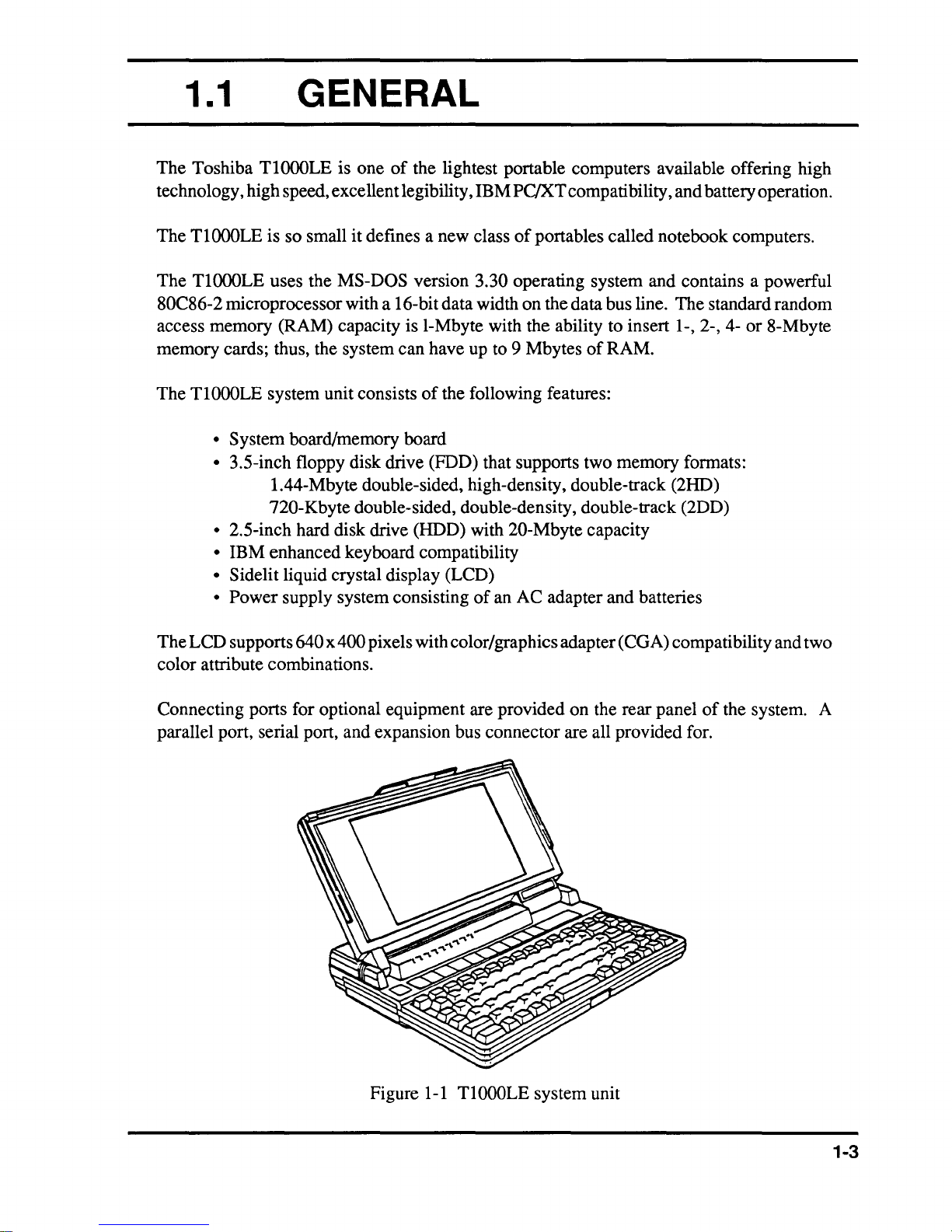
Figure
TlOOOLE
system unit
of
the system. A
1-3
1.2
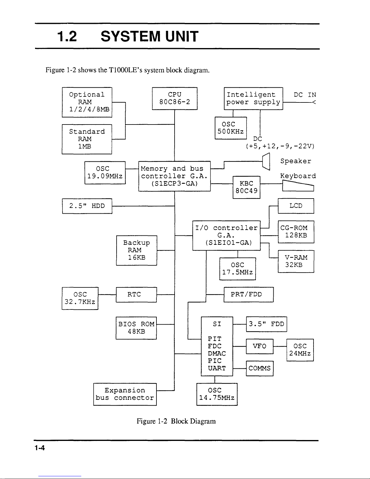
Figure 1-2 shows the T1000LE's system block diagram.
SYSTEM UNIT
Optional
RAM
1/2/4/8MB
Standard
RAM
1MB
OSC
19.09MHz
2.5"
HDD
r--
I---
I---
Memory
controller
Backup
RAM
16KB
CPU
80C86-2
and
bus
G.A.
(SlECP3-GA)
OSC
500KHz
W
I/O
controller
G
.A.
(SlEI01-GA)
17.5MHz
Intelligent
power
OSC
supply
DC
(+5,+12,-9,-22V)
KBC
80C49
Speaker
~
r-1
-
~
CG-ROM
128KB
V-RAM
32KB
DC
LCD
I N
<
I
1-4
OSC
32.7KHz
Expansion
bus
connector
RTC
BIOS
48KB
ROM
'---
Figure 1-2 Block Diagram
PIT
FDC
DMAC
PIC
UART
OSC
14.75MHz
SI
PRT/FDD
3
-1
-1
5
.
VFO
COMMS
-1
"
J
FDD
t-
I
OSC
24MHz
The system board in the
• Central processing unit: CPU (80C86-2)
The
CPU is a 16-bit microprocessor operating at 9.54MHz
or
4.77MHz clock speed.
• Super integration: SI (T9776)
The
SI stores the following components:
Direct Memory Access controller:
Programmable interrupt controller:
Programmable interval timer:
Floppy disk controller:
Universal asynchronousreceiver
and transmitter:
• Variable frequency oscillator: VFO (TC8568)
VFO chip is used for FDD control logic.
The
TlOOOLE
is composed
of
the following major components:
DMAC (TMP82C37
PIC (TMP82C59A)
PIT (TMP82C53)
FDC (TC8565)
SIO (TC8570)
A)
• Real time clock: RTC (TC8521)
The R TC has memory in the chip which keeps the date, time,
and system configuration with an RTC battery.
• Keyboard controller: KBC (TMP80C49)
• Memories:
Standard RAM:
Backup RAM:
BIOS ROM:
Video RAM:
CGROM:
I Mbyte
16
Kbytes
48 Kbytes
32 Kbytes
128 Kbytes
• Gate arrays:
Memory and bus controller gate array:
I/O controller gate array:
SIECP3-GA (184-pin)
S
lEIOI-GA
(184-pin)
1-5
• Oscillators: OSC
32.768KHz OSC
19.0909lMHz
(Xl)
is used for the RTC.
OSC (X2) is used for the CPU.
l4.7456MHz OSC (X3) is used for the SIO.
24MHz OSC (X4) is used for the VFO.
l7.5MHz
500KHz OSC
The
OSC (X5) is used for the LCD.
location
(X50l)
of
these OSCs are shown in Appendix A.
is used for the CPU
of
the intelligent power supply.
1-6
1.3
3.5-INCH FLOPPY DISK
DRIVE
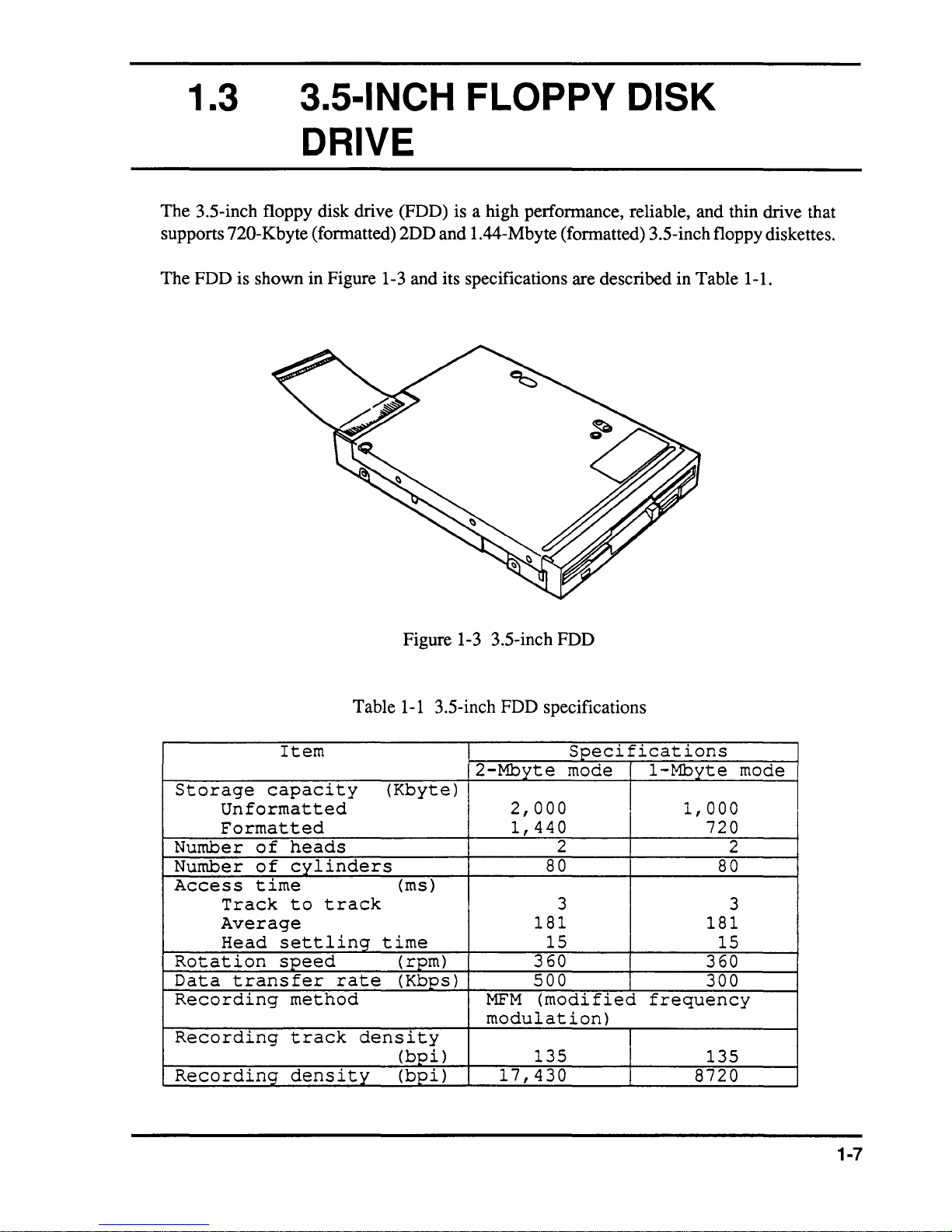
The 3.5-inch floppy disk drive (FDD) is a high perionnance, reliable, and thin drive that
supports
The FDD is shown in Figure 1-3 and its specifications are described in Table 1-1.
720-Kbyte (fonnatted) 2DD and 1.44-Mbyte (fonnatted) 3.5-inch floppy diskettes.
Storage
Unformatted
Formatted
Number
Number
Access
Track
Average
Head
Rotation
Data
Recording
Recording
Recording
transfer
Item
capacity
of
heads
of
cylinders
time
to
settling
speed
method
track
density
Table
track
rate
density
Figure 1-3 3.5-inch FDD
1-1
3.5-inch FDD specifications
2-Mbyte
(Kbyte)
2,000
1,440
(ms)
181
time
(rpm)
(Kbps)
MFM
modulation)
(bpi)
(bpi)
360
500
(modified
135
17,430
Specifications
mode
2
80
3
15
1-Mbyte
1,000
720
80
181
15
360
300
frequency
135
8720
mode
2
3
1-7
1.4
2.S-INCH HARD DISK
DRIVE
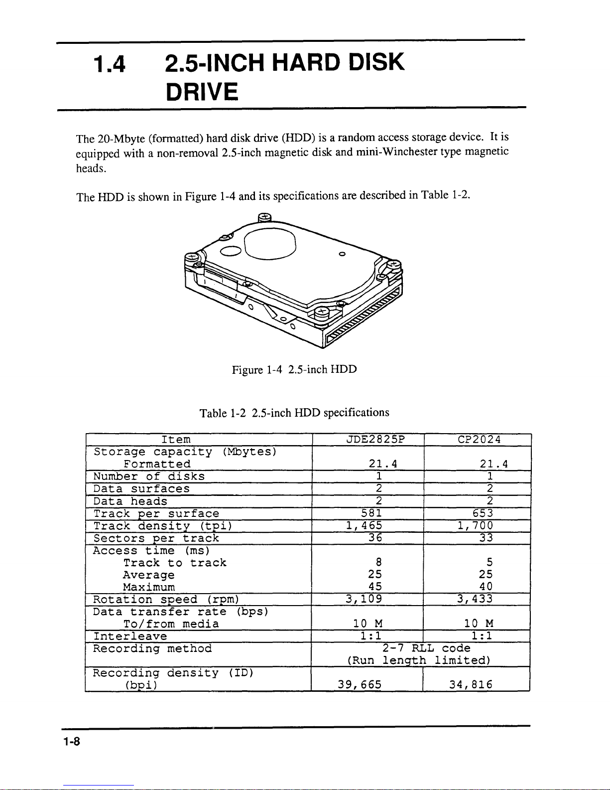
The 20-Mbyte (formatted) hard disk drive (HDD) is a random access storage device. It is
equipped with a non-removal 2.5-inch magnetic disk and mini-Winchester type magnetic
heads.
The HDD is shown in Figure 1-4 and its specifications are described in Table 1-2.
Storage
Formatted
Number
Data
Data
Track
Track
Sectors
Access
Rotation
Data
Interleave
Recording
Recording
surfaces
heads
per
density
Track
Average
Maximum
transfer
To/from
(bpi)
Item
capacity
of
disks
surface
per
time
to
speed
method
density
Figure 1-4 2.5-inch HDD
Table 1-2 2.5-inch HDD specifications
JDE2825P
(Mbytes)
(tpi)
track
(ms)
track
(rpm)
rate
media
(bps)
( ID)
1,465
3,109
(Run
39,665
21.4
1
2 2
2 2
581
36
8 5
25 25
45
3,433
10
M
1:1
2-7
RLL
length
code
limited)
I
34,816
CP2024
21.4
1
653
1,700
33
40
10
M
1:1
1-8
1.5 KEYBOARD
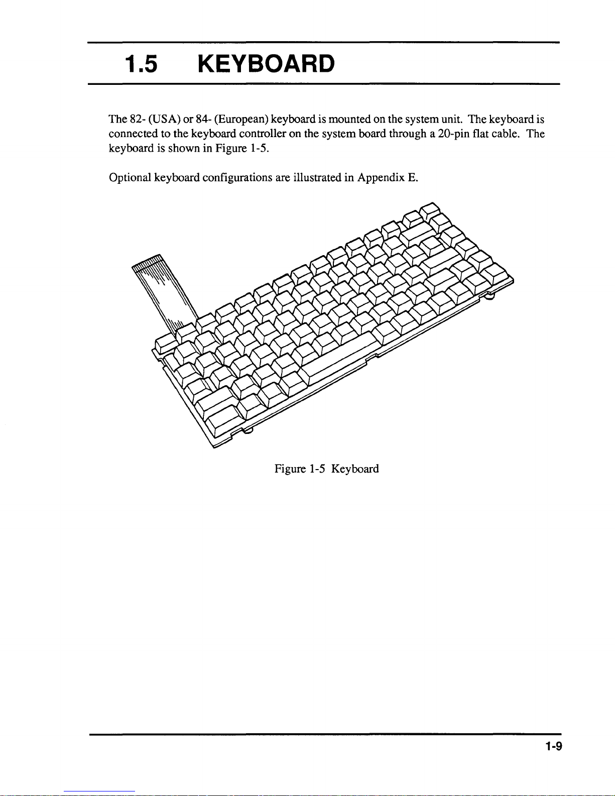
The 82- (USA)
connected to the keyboard controller on the system board through a
keyboard is shown in Figure 1-5.
Optional keyboard configurations are illustrated in Appendix
or
84- (European) keyboard is mounted on the system unit. The keyboard is
E.
20-pin flat cable. The
Figure 1-5 Keyboard
1-9
1.6
SIDELIT LIQUID CRYSTAL
DISPLAY
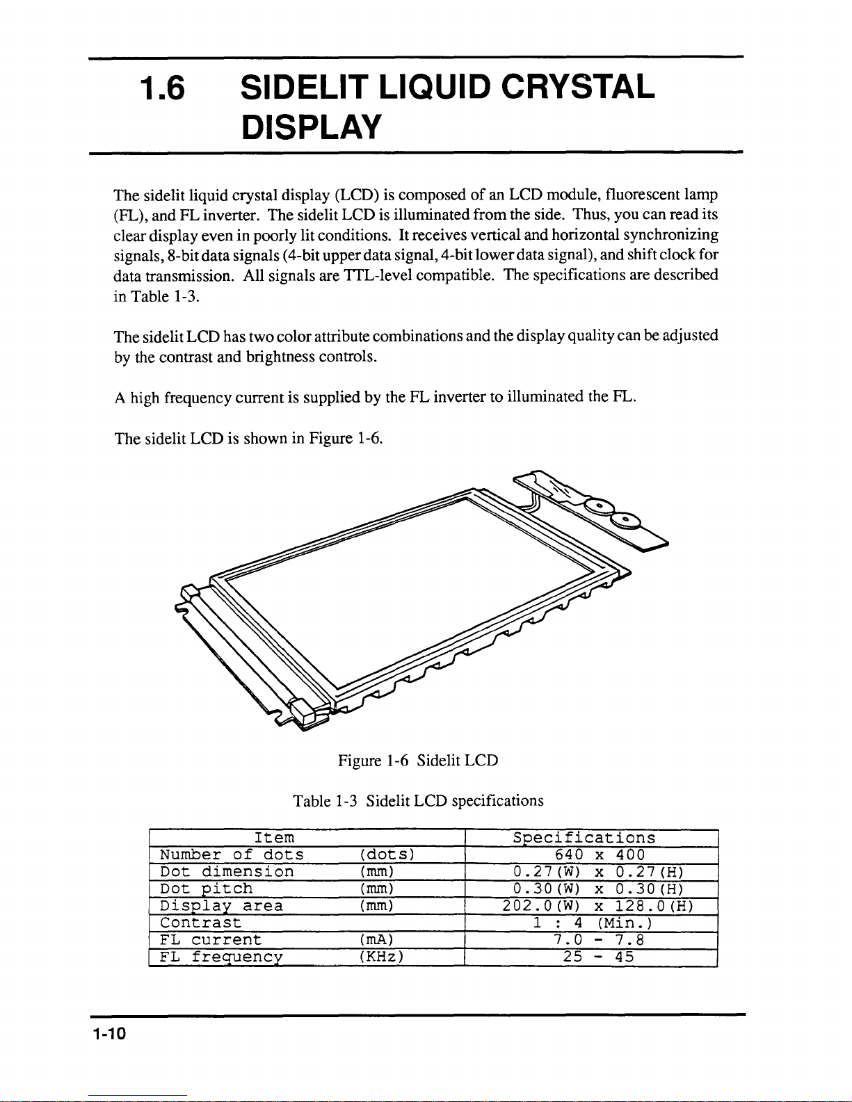
The
sidelit liquid crystal display (LCD) is
(FL),
and
FL
inverter.
1-3.
LCD
even
data
has
and
clear display
signals, 8-bit
data
transmission. All signals are TTL-level compatible.
Table
in
The
sidelit
by
the contrast
The
sidelit
in
poorly lit conditions. It receives vertical
signals (4-bit upper data signal, 4-bit
two
color
brightness controls.
LCD
attribute combinations
composed
is illuminated
of
an
LCD
module, fluorescent lamp
from
the side. Thus, you
and
horizontal synchronizing
lower
data
signal), and shift clock
The
specifications are described
and
the display quality
can
can
be adjusted
read
its
for
A high frequency
The
sidelit
LCD
current
is
shown
is supplied
in Figure 1-6.
by
Figure 1-6
the
FL
inverter to illuminated the FL.
Sidelit
LCD
Item
Number
Dot
Dot
Display
of
dots
dimension
pitch
area
Contrast
FL
current
FL
frequency
1-10
Table
1-3 Sidelit
(dots)
(rnm)
(rnm)
(rnm)
(rnA)
(KHz)
LCD
specifications
Specifications
640
0.27(W)
0.30(W)
202.0(W)
1
4
:
7.0
25
x
400
x
0.27(H)
x
0.30(H)
x
128.0(H)
(Min.
-
7.8
-
45
)
2.1
The problem isolation procedures described in Part 2 are used to isolate defective field
replaceable units (FRUs). The FRUs covered are:
GENERAL
1.
2. System board
3.
4.
5.
6.
Test program operations are described in Part 3 and detailed replacement procedures are
described in Part
The following items are necessary for implementing the problem isolation procedures:
1.
2. Phillips head screwdriver
3.
4. Cleaning disk kit (for FDD testing)
5. Printer port LED
6.
7. Multimeter
Power supply unit
FDD
HDD
Keyboard
Display
4.
T1000LE Diagnostics Disk
Work disk (for FDD testing)
RS-232-C, printer wraparound connectors
The problem isolation flowchart described in Section 2.2 can
isolation procedures are necessary to isolate a
TlOOOLE
problem.
be used to determine which
2-3

2.2
PROBLEM ISOLATION
FLOWCHART
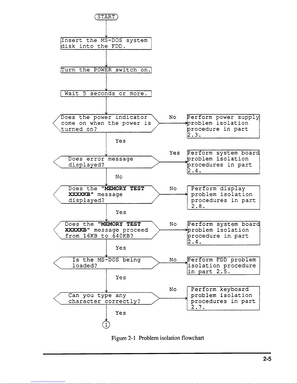
The flowchart in Figure 2-1 is used as a guide for determining which FRU is defective. Please
confIrm
the following before performing the flowchart procedures.
1.
2.
Disconnect all optional equipment.
Remove any disk in the FDD.
2-4
!IInsert
disk
the
into
(STjT)
I
'It'
MS-DOS
the
FDD.
system
!
lTurn
I
Wait
Does
corne
turned
Does
displayed?
Does
XXXXKB"
displayed?
the
5
the
on
POWER
seconds
power
when
on?
error
the
message
switch
or
indicator
the
power
Yes
message
No
"MEMORY
Yes
on.1
more.
TEST
is
J
No
Yes
No
~erform
~roblem
procedure
2.3.
~erform
problem
procedures
2
.4.
Perform
problem
procedures
2 . 8 .
power
isolation
in
part
system
isolation
in
display
isolation
in
supply
board
part
part
Does
XXXXKB"
from
Is
the
16KB
the
loaded?
Can
you
character
"MEMORY
message
to
640KB?
Yes
MS-DOS
Yes
type
any
correctly?
Yes
,
1
Figure
TEST
proceed
being
2-1
Problem
No
No
No
isolation
Perform
problem
procedure
2.4.
Perform
isolation
in
part
Perform
problem
procedures
2.7.
flowchart
system
isolation
in,
part
FDD
problem
procedure
2.5.
keyboard
isolation
in
board
part
2-5
1
Insert
disk
type
press
Perform
Is
an
the
diagnostics
System
the
into
diagnostics
the
A>T1000LE
Enter.
the
each
error
is
(
END)
detected
normal.
FDD,
then
and
test.
program?
No
in
I
Yes
After
which
test
error.
relevant
isolation
as
confirming
diagnostic
detected
Perform
problem
indicated
an
the
procedures
next
page.
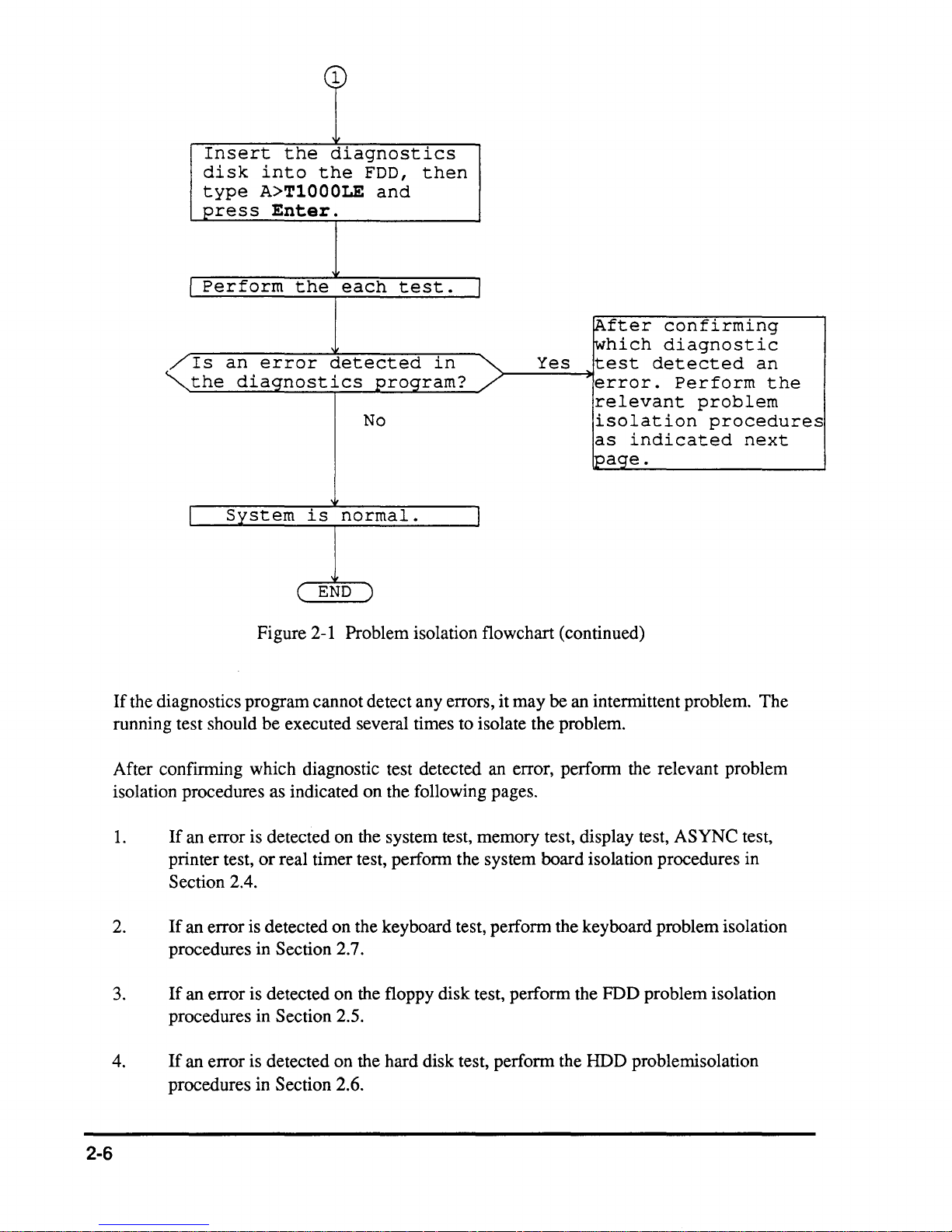
Figure 2-1 Problem isolation flowchart (continued)
If
the diagnostics program cannot detect any errors,
running test should be executed several times to isolate the problem.
After confirming which diagnostic test detected an error, perform the relevant problem
isolation procedures as indicated on the following pages.
1.
2.
3.
4.
If
an error is detected on the system test, memory test, display test, ASYNC test,
printer test,
Section 2.4.
If
an error is detected on the keyboard test, perform the keyboard problem isolation
procedures in Section 2.7.
If
an error is detected on the floppy disk test, perform the FDD problem isolation
procedures in Section 2.5.
If
an error is detected on the hard disk test, perform the HDD problemisolation
procedures in Section 2.6.
or
real timer test, perform the system board isolation procedures in
it
may be an intermittent problem. The
2-6
2.3
POWER SUPPLY PROBLEM
ISOLATION PROCEDURES
This section describes how to determine
PROCEDURE I and continue with the other procedures as instructed. The procedures
described in this section are:
PROCEDURE
PROCEDURE
PROCEDURE
1:
2:
3:
Indicator Check
Connector, Cable, and Power Switch Check
Replacement Check
if
the power supply is defective. Start with
2-7
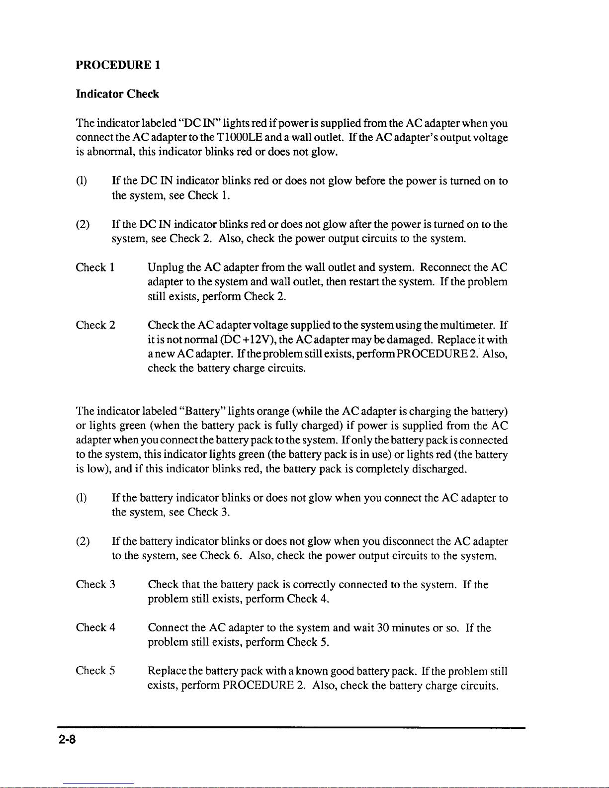
PROCEDURE 1
Indicator Check
The indicator labeled
connect the A C adapter to the T
is abnonnal, this indicator blinks red
(1)
If
the DC IN indicator blinks red
the system, see Check
(2)
If
the DC IN indicator blinks red
"DC
IN" lights red
if
power is supplied from the AC adapter when you
l000LE and a wall outlet.
or
does not glow.
or
does not glow before the power is turned on to
1.
or
does not glow after the power is turned on to the
If
the A C adapter's output voltage
system, see Check 2. Also, check the power output circuits to the system.
Check 1
Unplug the AC adapter from the wall outlet and system. Reconnect the AC
adapter to the system and wall outlet, then restart the system.
Check 2
still exists, perfonn Check
Check the AC adapter voltage supplied to the system using the multimeter.
2.
it is not nonnal (DC + 12V), the AC adapter may be damaged. Replace it with
a new AC adapter.
If
the problem still exists, perfonn PROCEDURE
check the battery charge circuits.
The indicator labeled
or
lights green (when the battery pack is fully charged)
adapter when you connect the battery pack to the system.
"Battery" lights orange (while the AC adapter is charging the battery)
if
power is supplied from the AC
If
only the battery pack is connected
to the system, this indicator lights green (the battery pack is in use)
is low), and
if
this indicator blinks red, the battery pack is completely discharged.
If
the problem
2.
or
lights red (the battery
If
Also,
(1)
If
the battery indicator blinks or does not glow when you connect the AC adapter to
the system, see Check
(2)
If
the battery indicator blinks or does not glow when you disconnect the AC adapter
to the system, see Check
Check 3
Check that the battery pack is correctly connected to the system.
problem still exists, perfonn Check 4.
Check 4
Connect the AC adapter to the system and wait
problem still exists, perfonn Check 5.
Check 5
Replace the battery pack with a known good battery pack.
exists, perfonn
2-8
3.
6.
Also, check the power output circuits to the system.
30 minutes or
If
the problem still
PROCEDURE
2.
Also, check the battery charge circuits.
so.
If
If
the
the

Check 6
Check that the battery pack is correctly connected to the system.
problem still exists, perfonn Check 7.
If
the
Check 7
Replace the battery pack with a known good one.
perfonn
PROCEDURE 2.
If
the problem still exists,
2-9

PROCEDURE 2
and
Connector, Cable,
The battery pack is connected directly to the power supply board and an optional battery cable
is connected to the system board through the power supply board on the back
The sub battery and power switch cable are connected directly to the system board. Any
these cables may be disconnected
cables. Disassembly procedures are described in
Power Switch Check
or
damaged. Disassemble the system unit to checking the
Part 4.
of
the top cover.
of
Check 1
Check 2
Check 3
Check that the following cables are correctly connected to the system board,
power supply board, and LED board.
LED board
PS board PJ802
Power switch --------> System board
If
any
of
If
the problem still exists, perform Check 2.
Recheck the above cables using the multimeter.
damaged, replace them and restart the system.
perform Check
Check the power switch contact using the multimeter.
contact is bad, replace the power switch with a new one and restart the system.
If
the problem still exists, perform PROCEDURE 3.
PJ601 <--------> System board
PJ602 <--------> PS board
PJ603 <--------> System board
<--------
PJ805 <--------> DC jack
these cables are disconnected, connect them and restart the system.
3.
> System board
PJ503
PJ803
PJ505
PJ502
PJ702
PJ501
If
any
of
the cables look
If
the problem still exists,
If
the power switch
2-10
PROCEDURE 3
Replacement Check
In this system unit, the power board, DC-IN board, LED board, and system board are
connected with the power supply circuits, and the LED board is connected with the indicator
circuits. Any
voltages and/or replace them. Replacement procedures are described in Part 4.
of
these boards may be damaged. Perform Checks 1 through 4 to check the
Check 1
Check 2
Check 3
Check 4
Replace the DC-IN board with a new one and restart the system.
problem still exists, perform Check
Replace the power board with a new one and restart the system.
2.
If
the problem
still exists, perform Check 3.
Replace the LED board with a new one and- restart the system.
If
the problem
still exists, perform Check 4.
Replace the system board with a new one.
If
the problem still exists, other
units may be damaged. Continue troubleshooting the system unit.
If
the
2-11

2.4 SYSTEM BOARD PROBLEM
ISOLATION PROCEDURES
This section describes how to detennine
PROCEDURE 1 and continue with the other procedures as instructed. The procedures
described in this section are:
PROCEDURE
PROCEDURE
PROCEDURE
1:
2:
3:
Message and Beep Sound Check
Printer Port LED Check
Test Program Check
if
the system board is defective. Start with
2-12
PROCEDUREl
Message
After the power is turned on, the system performs the initial reliability test (IRT) which is a
program stored in
the system board.
If
an error message appears on the screen, perform Check
the screen, perform
Check 1
Check 2
and
Beep Sound Check
BIOS ROM on the system board. The IRT tests and initializes each IC on
1,
and
if
nothing is displayed on
PROCEDURE
If
the following error message appears on the screen, press any key. This
program confirms the current system configuration and the configuration
stored to RTC memory.
appear. You can easily set the current configuration in the RTC memory by
pressing any key.
***SYSTEM CONFIGURATION ERROR***
A
checksum
Press
If
the following message appears, press any key. At this time the resumed data
will be erased.
any
2.
If
they are different, the following message will
If
another error message appears, perform Check
error
key
If
another error message appears, perform Check
occurred
for
default
in
set
the
configuration
....
2.
RAM.
3.
WARNING:
PRESS
ANY
RESUME
KEY
TO
FAILURE.
CONTINUE.
2-13
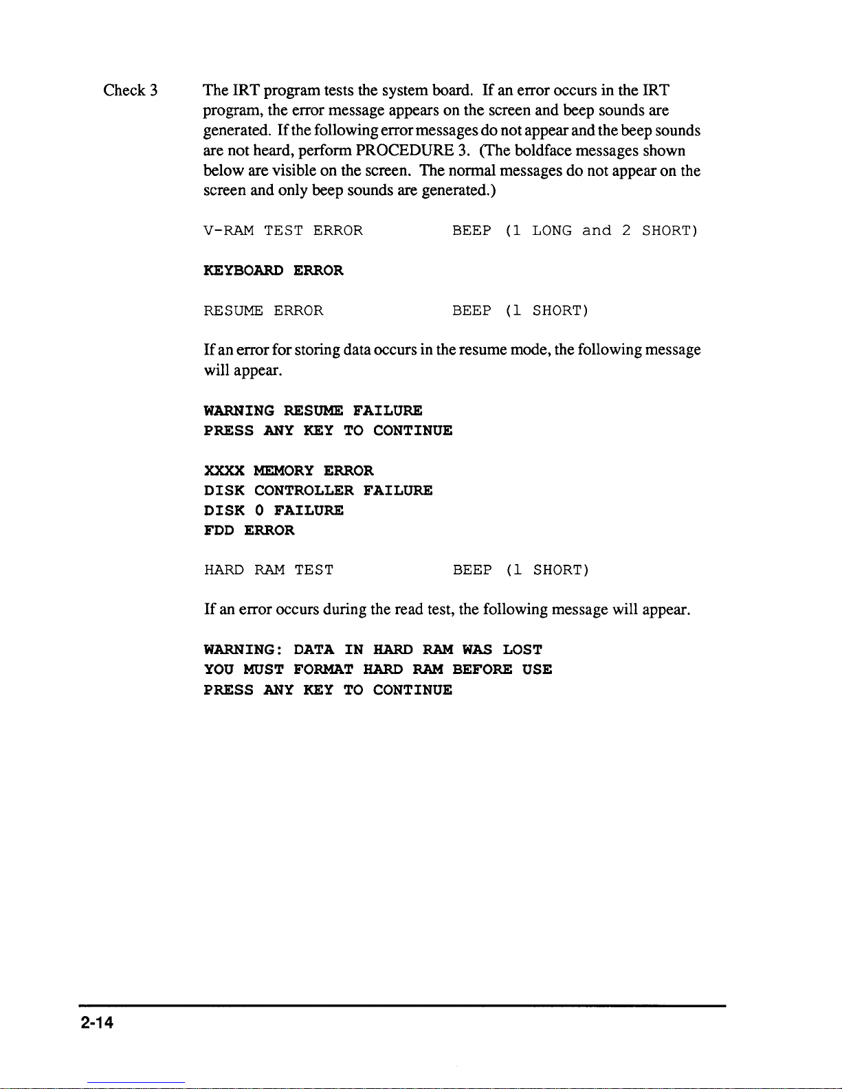
Check 3
The IRT program tests the system board.
program, the error message appears on the screen and beep sounds are
generated.
are not heard, perform
below are visible on the screen. The normal messages do not appear on the
screen and only beep sounds are generated.)
If
the following error messages do not appear and the beep sounds
PROCEDURE
If
an error occurs in the IRT
3.
(The boldface messages shown
V-RAM
KEYBOARD
RESUME
If
an error for storing data occurs in the resume mode, the following message
will appear.
WARNING
PRESS
XXXX
DISK
DISK
FDD
HARD
If
an error occurs during the read test, the following message will appear.
TEST
ERROR
ERROR
ERROR
RESUME
ANY
KEY
MEMORY
ERROR
CONTROLLER
0 FAILURE
ERROR
RAM
TEST BEEP (1
FAILURE
TO
CONTINUE
FAILURE
BEEP (1
BEEP (1
LONG
SHORT)
SHORT)
and
2
SHORT)
2-14
WARNING:
YOU
MUST
PRESS
ANY
DATA
IN
FORMAT
KEY
TO
HARD
HARD
RAM
RAM
CONTINUE
WAS
LOST
BEFORE USE
PROCEDURE
2
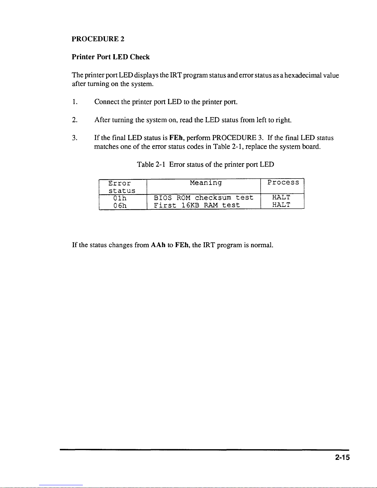
Printer
Port
LED
Check
The printer port LED displays the IRT program status and error status
after turning on the system.
1.
Connect the printer port LED to the printer port.
2. After turning the system on, read the LED status from left
3.
If
the final LED status is
of
matches one
the error status codes in Table 2-1, replace the system board.
Table 2-1 Error status
Error
FEh,
perform PROCEDURE
of
the printer port LED
Meaning
3.
If
Process
status
Olh
06h
BIOS
First
ROM
l6KB
checksum
RAM
test
test
as
a hexadecimal value
to
right.
the final LED status
HALT
HALT
If
the status changes from AAh
to
FEh,
the IR T program is normal.
2-15
PROCEDURE 3
Test Program Check
The test program which is stored in the
TlOOOLE
Diagnostics Disk has several programs
for testing the system board. Perform the following tests. Detailed operation is described
in Part
3.
System test
Memory test
Display test
Printer test
ASYNC test
Real timer test
If
an error is detected during the above tests, replace the system board.
If
the problem still
exists, another unit may be defective. Continue troubleshooting the system unit.
2-16
2.5
FLOPPY DISK DRIVE
PROBLEM ISOLATION
PROCEDURES
This section describes how to determine
PROCEDURE 1 and continue with the other procedures as instructed. The procedures
described in this section are:
PROCEDURE
PROCEDURE
PROCEDURE
1:
2:
3:
Format Check
Test Program Check
Connector Check
if
the floppy disk drive is defective. Start with
2-17
PROCEDUREl
Format
Prepare a new floppy disk by fonnatting
If
the floppy disk does not fonnat correctly, check the following items.
Check 1
Check 2
Check 3
Check
it
using the MS-DOS
Check that the FDD indicator lights.
3.
If
it
lights,
Check that the
When
When
If
If
the media type is 2DD, use the FORMAT/3 command.
the media type is 2HD, use the FORMAT command.
the
FORMAT
the
FORMAT
still exists,
perfonn
MS-DOS
Check 2.
FORMAT
command was used correctly,
command was not used correctly,
perfonn
Check 3.
Ifitdoes
command was used correctly.
FORMAT
not light, perfonn PROCEDURE
perfonn
Clean thereadlwrite head using the 3.5-inch FDD cleaning kit.
still exists,
perfonn
PROCEDURE 2.
try
command.
Check 3.
again.
If
the problem
If
the problem
2-18
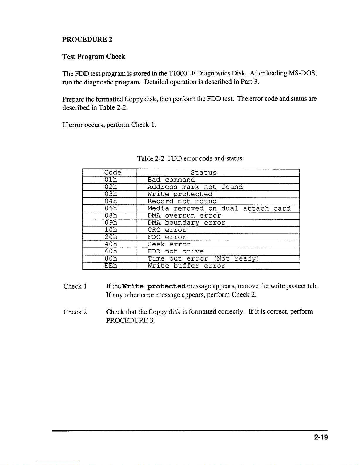
PROCEDURE 2
Test Program Check
The FDD test program is stored in the
run the diagnostic program. Detailed operation is described in Part 3.
Prepare the formatted floppy disk, then perform the FDD test. The error code and status are
described in Table 2-2.
If
error occurs, perform Check
Table 2-2 FDD error code and status
Code
Olh
02h
03h
04h
06h
OSh
09h
lOh
20h
40h
60h
SOh
EEh
Bad
Address
Write
Record
Media
DMA
DMA
CRC
FDC
Seek
FDD
Time
Write
1.
command
overrun
boundary
error
error
not
TlOOOLE
Status
mark
protected
not
removed
error
drive
out
error
buffer
Diagnostics Disk. After loading MS-DOS,
not
found
found
on
dual
attach
card
error
error
(Not
ready)
error
Check 1
Check 2
If
the
Wr i te
U any other error message appears, perform Check 2.
Check that the floppy disk is formatted correctly.
PROCEDURE 3.
protected
message appears, remove the write protect tab.
If
it is correct, perform
2-19
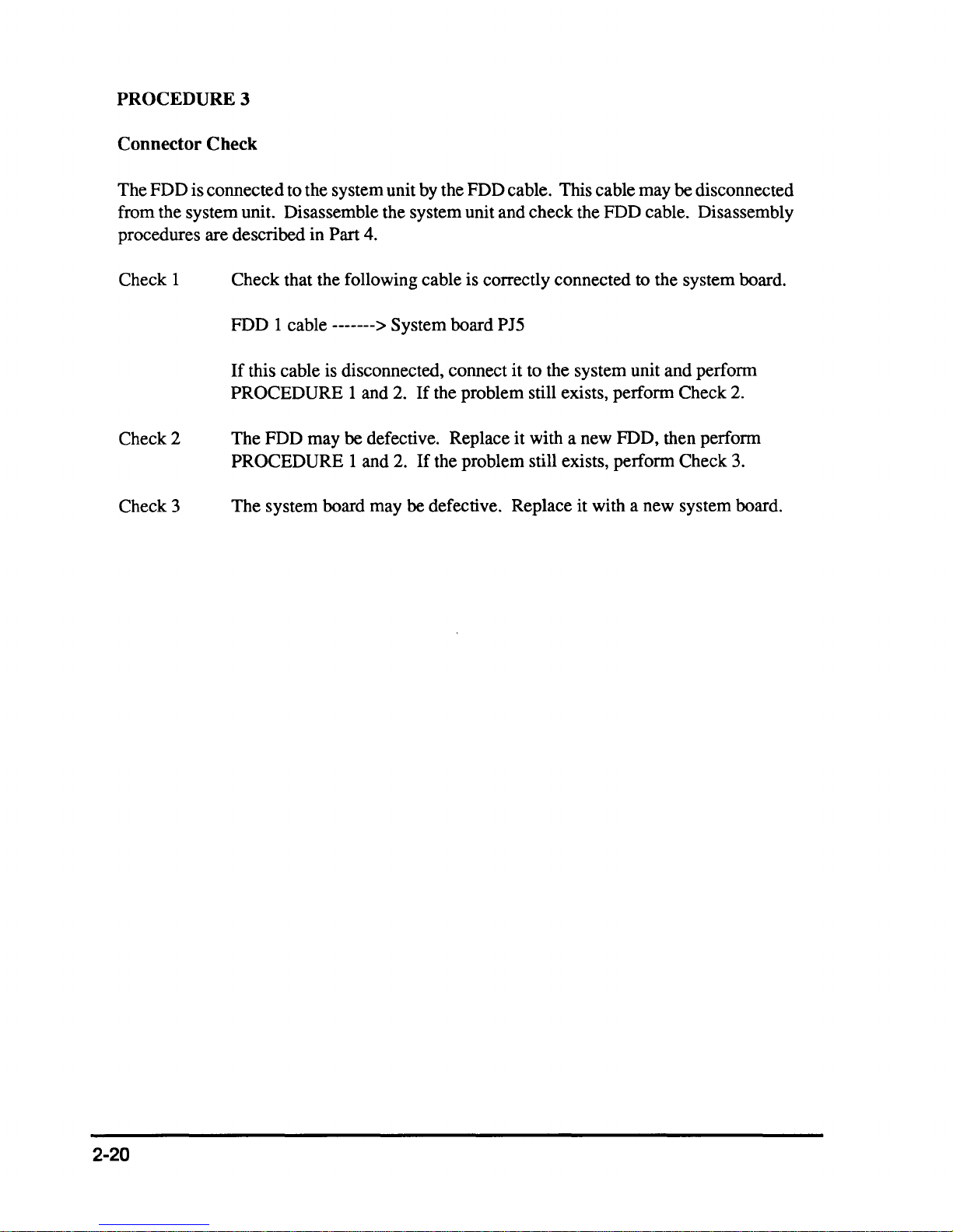
PROCEDURE 3
Connector Check
The FDD is connected to the system unit by the FDD cable. This cable may
be disconnected
from the system unit. Disassemble the system unit and check the FDD cable. Disassembly
procedures are described in
Check 1
Check that the following cable is correctly connected to the system board.
FDD 1 cable
If
this cable is disconnected, connect it to the system unit and perfonn
PROCEDURE 1 and 2.
Check 2
The FDD may be defective. Replace it with a new FDD, then perfonn
PROCEDURE 1 and 2.
Check 3
The system board may
Part 4.
-------> System board PJ5
If
the problem still exists, perfonn Check
If
the problem still exists, perfonn Check 3.
be defective. Replace it with a new system board.
2.
2-20
2.6 HARD DISK DRIVE PROBLEM
ISOLATION PROCEDURES
This section describes how to determine if the hard disk drive is defective. Start with
PROCEDURE 1 and continue with the other procedures
described in this section are:
as
instructed. The procedures
PROCEDURE
PROCEDURE
PROCEDURE
CAUTION: The contents
problem isolation procedures. Before continuing, transferthe contents
the hard disk to floppy disks. This can be done with the MS-DOS BACKUP command. (See the MS-DOS
1:
2:
3:
Logical Format Check
Test Program Check
Connector Check
of
the hard disk will
be
erased by performing the HDD
manualfor
details.)
of
2-21
PROCEDUREl
Logical Format Check
Using the MS-DOS system disk, make a partition
command. Then format the hard disk by using the
Is
after FORMAT to transfer the system program.
If
normal operation is restored, the HDD is normal.
perform
PROCEDURE
2.
of
the hard disk by using the FDISK
FORMAT command. At this time enter
If
normal operation is not restored,
2-22
PROCEDURE
Test
Program
2
Check
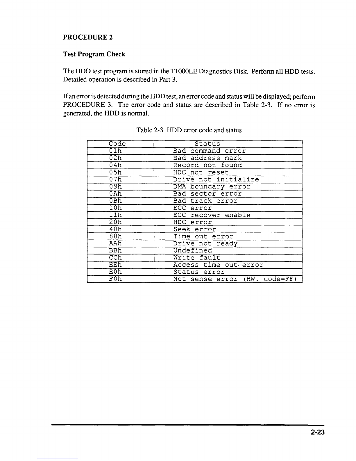
The HDD test program is stored in the
Detailed operation is described in
If
an error is detected during the HDD test, an error code and status will be displayed; perform
PROCEDURE 3. The err0r code and status are described in Table 2-3.
generated, the HDD is normal.
Table 2-3 HDD error code and status
Code
Olh
02h
04h
OSh
07h
09h
OAh
OBh
lOh
llh
20h
40h
SOh
AAh
BBh
CCh
EEh
EOh
FOh
TlOOOLE
Part
3.
Bad
Bad
Record
HDC
Drive
DMA
Bad
Bad
ECC
ECC
HDC
Seek
Time
Drive
Undefined
Write
Access
Status
Not
Diagnostics Disk. Perform all HDD tests.
If
no error is
Status
command
address
not
not
not
boundary
sector
track
error
mark
found
reset
initialize
error
error
error
error
recover
enable
error
error
out
error
not
ready
fault
time
out·
error
error
sense
error
(HW.
code=FF)
I
2-23
PROCEDURE
3
Connector Check
The
packed HDD is connected to the system board by the HDD connector. Disassemble the
system unit and check the
is disconnected, connect
problem still exists, perform Check
HDD.
it
to the system board and perform PROCEDURES I and 2.
Detailed procedures are described in Part 4.
If
1.
this cable
If
the
Check I
Check 2
The HDD may be damaged. Replace the HDD unit with a new one.
still occurs, perform Check
The
system board may be damaged. Replace the system board with a new one.
2.
If
the error
2-24
 Loading...