

Page 1
Intelligent Image Sensor
iIS-010 series
TK6234A5 : iIS-010
TK6238A7 : iIS-011
TK6240A5 : iIS-012
ProductSpecification
1. Product Description·································2
2. Features ···················································2
3. Configuration···········································4
4. Name and Function of Parts·····················6
5. Specification············································9
6. External View········································22
• Restriction For Use·································26
• Precautions ·············································27
• Exemption Clauses ·································27
The contents of this product specification may be revised without notice to reflect future product
modifications. Please confirm the functions and the spec ifica tio ns on the latest specification sheet.
(Total 29 pages)
D4130145B
Page 2

iIS-010 series product specification
Ver. B (Oct. 12 2004)
1. Product Description
"intelligent image sensor" iIS-010 series is an integrated image processing system consists of CCD
camera head, control unit, and application software. iIS-010 series is a pre-packaged solution designed to
simplify the deployment of machine vision in industrial applications.
2. Features
(1) High measurement accuracy
High measurement precision finds small defects in manufactured parts.
(2) Double speed VGA sensor
Remote head VGA sensor connected through a single cable with all camera electronics contained
within the iIS assembly. The camera electronics support a 60Hz progressive scan frame rate.
(3) Interface for industrial applications
Industrial and intelligent I/O interfaces for part type (job code), part inspection, part decision and light
control.
(4) Standard interfaces
Standard serial and Ethernet 10/100baseT communication interfaces for configuration and data
reporting.
(5) Graphical user interface
Intuitive step-by-step configuration and monitoring GUI, accessible through a standard Microsoft
browser page and available in two languages (English and Japanese).
(6) Local Scaling / Global Scaling
Simple calibration procedure which factors out both perspective and non-linear lens distortions,
provides high measurement accuracy. And measurement in metric, English or pixel, supports unique
system requirements.
(7) History reports
Customer-defined history reports including parts images records information on recent passed, failed
and reworked parts; key measures; specifics on which part failed to enable diagnosis. Provides a history
of recent good and bad label images enables you to monitor and spot error trends on a line.
2
D4130145B
Page 3

iIS-010 series product specification
Ver. B (Oct. 12 2004)
(8) Gauge Application
Comprehensive set of gauging tools gives you the ability to precisely and accurately measure lines,
angles between lines, ellipses and circles (center, circularity or out-of-round, nicks, major and minor
axes),arcs (centers and lengths), Annuli, thread spacing (“wave tool ”),multiple measures of length and
spacing of parts such as pins on an electrical connector (“rake tools ”),and other part measures.
(9) Label Application
User-defined features including label rotation, movement, rejection thresholds enables you to define
your label quality criteria. All settings are quickly defined and changed using a sliding bar from “lower”
to “higher”. Automatic learning of good labels, using a proprietary neural net learns labels and variations.
3
D4130145B
Page 4

iIS-010 series product specification
3. Configuration
Hardware
iIS-010 Camera Head: 20mm square type ···················································1
Camera cable: Direct Fixing (2m) ··················································1
*Cable fixing direction: (viewed from rear) Right
Control Unit (iIS-010 series compatible)········································1
iIS-011 Camera Head: φ17mm type ····························································1
Camera cable: Separated type (2m) ················································ 1
*Cable fixing direction: (viewed from rear) Rear
Control Unit (iIS-010 series compatible)········································1
iIS-012 Camera Head: C mount head type ··················································1
Camera cable: Direct Fixing (2m) ··················································1
*Cable fixing direction: (viewed from rear) Right
Ver. B (Oct. 12 2004)
Control Unit (iIS-010 series compatible)········································1
・Accessories
Ethernet crossover cable KB-10T5-03CK (Sanwa-supply, 3m) ·············································1
DIN rail mounting kit CKD-80 (Takachi Denki)································································2
Screws for the mounting kit PB3X10BS-NI················································································4
Plug for power cable 39860-1002 (MOLEX, 2 terminal type)··········································1
Plug for parallel I/O cable 1-1546208-5 (AMP/Buchanan, 15 pin type)··································· 1
Floppy Disk Including switching applica t ion file················································1
Operation Manuals Basics (Japanese)············································································1
Basics (English)··············································································1
Applications (Japanese)··································································1
Applications (English)···································································· 1
Calibration sheet A4 size ··························································································· 1
* Ethernet® is a trademark of Xerox Corporation U.S.
4
D4130145B
Page 5

iIS-010 series product specification
Software
iIS Web pages for viewing on Internet Explorer® (Installed)
iWorks(Gauge) Application for Gauge (Auto download from the control unit)
iWorks(Label) Application for Label (Auto download from the control unit)
iAssistant Application for Upgrade (Auto download from the control unit)
iServer Application for monitoring connection status (Installed)
HTML Help Microsoft® online help for Gauge / Label application
Switch To Gauge Binary File for switching to Gauge (including in the floppy disk)
Switch to Label Binary File for switching to Label (including in the floppy disk)
Others ActiveX® control libraries (Auto download from the control unit)
* Microsoft®, Windows®, Microsoft® Internet Explorer, and ActiveX® are registered trademarks
of Microsoft Corporation, U.S., in the U.S. and other countries.
Ver. B (Oct. 12 2004)
Optional Accessories
Camera Lens
For iIS-010 Dedicated lenses (M10.5 P0.5 female)
For iIS-011 Dedicated lenses (M15.5 P0.5 male)
For iIS-012 C mount lenses
Camera mounting kit
For iIS-010 CPT4310A / CPT4310B
For iIS-011 CPT5130
For iIS-012 CPT5110
*Please contact your dealer / distributor for details of option units.
Peripheral Devices (compatibility verified)
DC Power supply PS5R-D24 (Idec)
PC DynaBook 2590X (Windows® 2000 Japanese / English)
Local Display RDF17S (Mitsubishi)
*Please contact your dealer / distributor for the other peripheral devices.
5
D4130145B
Page 6
iIS-010 series product specification
4. Name and Function of Parts
Ver. B (Oct. 12 2004)
1
ETHERNET
5
2
POWER LED1 LED2 LED3
CAMERA
DISPLAY RS232C
RESET
7
010
6
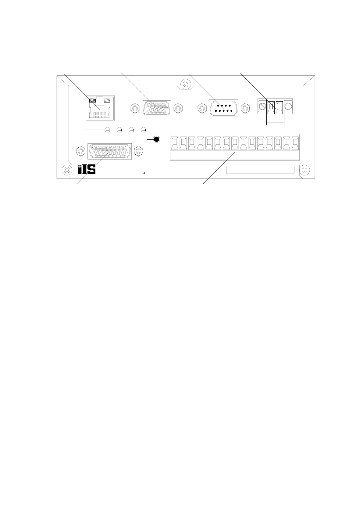
Figure 1. Control unit (Front-panel side)
1. RJ45 connector for Ethernet Connect with PC or PLC by using Ethernet cable.
2. Local Display connector
3 4
RDY
STR
GPO2
GPO1
GPO3
8
GPO0
COM1
TRIG
D.TRIG
POWER
GPI1
GPI0
V+
COM0
V-
GPI3
GPI2
SEL
A XGA Monitor can be connected directly to the control unit, for local display of the camera image.
3. RS-232C connector Connect with PC or PLC by using the crossover RS-232C cable.
4. Power connector Connect the DC Power Supply (+24V DC ±10%) to the control unit power connector.
5. LED indicator
POWER: power-on indicator - steady green
LED1: server “heartbeat” - slow flashing green
LED2: acquisition (frame) done (or processing start) ‐ rapid flashing green
LED3: reserved for future use ‐ steady off
6. Camera connector Connect the control unit and camera head with the camera cable provided with iIS-010 series kits.
7. Reset button Reset the control unit or reset to the factory default.
6
D4130145B
Page 7
iIS-010 series product specification
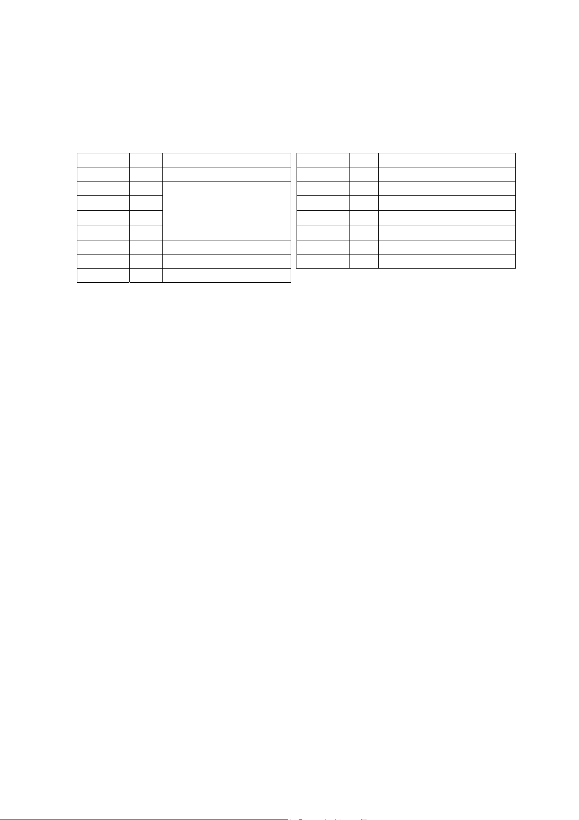
8. Parallel I/O 8 inputs and 7 outputs parallel I/O.
Table 1. Parallel I/O terminal functions
Ver. B (Oct. 12 2004)
NAME I/O Function Name I/O Function
I
COM0
GPI0
GPI1
GPI2
GPI3
SEL
D.TRIG
TRIG
COM0: Common input for all other inputs.
GPI0 ~ 3: 4 inputs for solution selection. This is a BCD code representing 16 different solutions that
Common for inputs COM1
I
I
Select solution input
(4bit, ID00~15)
I
I
I
Change solution input STR
I
Decision trigger input RDY
I
Inspection trigger input
GPO0
GPO1
GPO2
GPO3
O
Common for outputs
O
Result (Pass) output
O
RESERVE
O
O
O
O
Result (Recycle) output
Result (Reject) output
Strobe pulse output
Ready signal output
can be loaded.
SEL: 1 input for job change - This input will generate an interrupt to the CPU informing it that a
line changeover is taking place. The system will then load one of 16 predefined solutions
according to the BCD code present on the job selection inputs. During this process, the
ready signal will go OFF indicating a busy state.
D.TRIG: 1 decision trigger input representing detection of a valid part to make a decision on.
Decisions are queued following every inspection.
TRIG 1 inspection trigger input representing detection of a valid part to inspect.
COM1: Common output for all other outputs.
GPO0 ~ 3: 4 outputs for pass, fail, rework and reserve
STR: 1 strobe light control with offset and pulse width programmable.
RDY: 1 ready indicator. This OUTPUT will be active when the iIS system is available to process
parts. It is a level sensitive signal where a ON indicates the system is available and a OFF
indicates that it is busy, not configured or unable to continue due to a catastrophic event.
7
D4130145B
Page 8
iIS-010 series product specification
Ver. B (Oct. 12 2004)
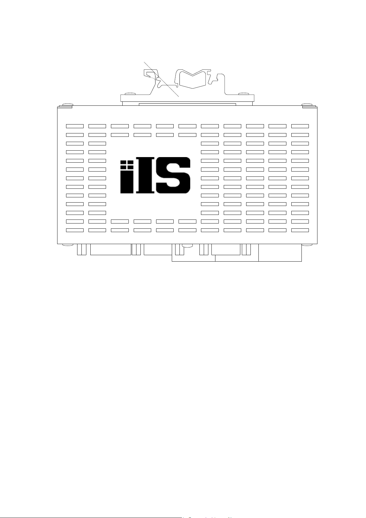
9
9. Mounting kits for DIN rail You can mount with 32mm / 35mm width type DIN rail.
Figure 2. Control unit (top view)
8
D4130145B
Page 9

iIS-010 series product specification
5. Specification
[General Specification]
Ver. B (Oct. 12 2004)
Power Supply +24V DC ±10% (Ripple voltage: 50mV
Power Consumption 10W or less (+24V DC)
Operating T emperature 0 °C ~ +40 °C
Operating Humidity 30 % ~ 85 %RH (No condensing)
Storage Temperature -20 °C ~ +60 °C
Storage Humidtity 10 % 95 %RH (No condensing)
EMC conditions (Electro-Magnetic Compatibility)
(Electro-Magnetic Interference) EN50081-2 (Examination level: EN55011-A) Conformity
EMI
(Electro-Magnetic Susceptibility) EN61000-6-2 Conformity
EMS
* Conformity of EMC conditions
About the conformity of the EMC standard of this machine, it has guaranteed in the cond itions
combined with the peripheral devices of the 3rd clause.
When used combining parts other than specification of our company, I ask you to have final
EMC conformity checked of a visitor with a machine and the whole equipment.
[Camera head specification]
Image sensor All Pixel's Data Read-out Interline CCD
Total pixels 692 (H) × 504 (V)
or less)
P-P
Valid pixels 648 (H) × 494 (V)
Unit cell size 7.4 (µm) × 7.4 (µm)
Sensitivity 400lx, F5.6 (Exposure time = 1/60s)
External Dimensions
iIS-010 20 (W) × 20 (H) × 25 (D) mm
iIS-011 φ17 × 36.2 (D) mm
iIS-012 φ35 × 40 (D) mm
Lens mount
iIS-010 Special mount (M10.5 P0.5 female)
iIS-011 Special mount (M15.5 P0.5 male)
iIS-012 C mount
Weight
iIS-010 Approx. 19g (Excluding cable)
iIS-011 Approx. 16g (Excluding cable)
iIS-012 Approx. 55g (Excluding cable)
Camera cable length 2m (iIS-010 series)
9
D4130145B
Page 10

iIS-010 series product specification
Ver. B (Oct. 12 2004)
Relative Spectrum Response (*Including lens characteristics, Excluding light source characteristics)
Sensitivity
Wave Length(nm)
Figure 3. Relative Spectrum Response
[Control Unit]
Camera input 1
V ideo output pixels 640 (H) × 480 (V)
Quantization 10bit gray scale
Processing 8bit gray scale
Video format Non-Interlace
Sensor Trigger mode Selectable Internal Timer or External trigger
Exposure time Settable from 1 to 1024 (1 step = Approx. 60µs)
Brightness Approx. 3 ~ 19 LSB (8 bit)
Contrast Approx. ±4dB
Processor 266MHz Intel compatible SOC processor
Memory 64MB image acquisition and processing
32MB program and solution (job) storage
Device Name NS2***** (Default)
IP address 192.168.0.100 (Default)
Subnet Mask 255.255.0.0 (Default)
MAC address 00-01-0D-**-**-** (* Unique ID)
DHCP Disabled (Default)
DHCP server Not Available (Default)
Primary WINS server 000.000.000.000 (Settable on the web page)
10
D4130145B
Page 11

iIS-010 series product specification
Secondary WINS server Not Available (Default)
Interfaces
Ethernet 1ch
Connector RJ-45
Table 2. Ethernet connector pin assignment
Pin # I/O Teminal function
1 O TD+ (Transmit data +)
2 O TD- (Transmit data -)
3 I RD+ (Receive data +)
4 - NC
5 - NC
6 I RD- (Transmit data -)
7 - NC
8 - NC
Connection Type 10/100 BaseT Ethernet
Ver. B (Oct. 12 2004)
IEEE 802.3 compatible
10/100 BaseT Auto Sence
Protocol HTTP, ICMP, DHCP, TCP/IP
LED indicator Orange indicates for working on 100BaseT
Green indicates for working on 10BaseT
Light on indicates for linking Ethern et
Blink indicates for working communication
Cables Twisted Pair (Category 5e or greater)
Maximum cable length 100m (Unshielded Twisted Pair cable)
DISPLAY 1ch
Connector D-SUB 15 pin, Right Angle, female
Table 3. Local Display connector pin assignment
Pin # Terminal Function Pin # Terminal Function
1 Red Data 9 NC
2 Green Data 10 GND
3 Blue Data 11 NC
4 NC 12 NC
5 GND 13 HSYNC
6 GND 14 VSYNC
7 GND 15 NC
8 GND
Scanning type Progressive
Video signal level 0.7V
(75Ω terminated)
P-P
11
D4130145B
Page 12

iIS-010 series product specification
Ver. B (Oct. 12 2004)
for sync on green, 1.0 V
(Video signal: 0.7 V
(75 Ω terminated)
P-P
, sync signal: 0.3 V
P-P
P-P
)
Sync signal Separate sync
Horizontal sync frequency 56.4kHz
Vertical sync frequency 70Hz
Image resolution 1024 × 768 × 16bpp
Sampling resolving power R=5bit, G=6bit, B=5bit
RS-232C 1ch
Connector D-SUB 9pin, Male
Table 4. RS-232C connector pin assignment
Pin # I/O Description Pin # I/O Description
1 - NC 6 - NC
2 I RX (Receive Data) 7 - NC
3 O TX (Transmit Data) 8 - NC
4 - NC 9 - NC
5 - Ground
Control type RS-232C (Non-procedure)
Bit rate 110 / 300 / 600 / 1200 / 2400 / 4800 / 9600 / 19200 / 38400 /
57600 / 115200 bps
*230400 / 460800 / 921600 bps are not supported.
Data bits 5 / 6 / 7 / 8
Stop bits 1 / 1.5 / 2
Parity Odd / Even / None / Mark / Space
Flow Control None
Parallel I/O 8 inputs (COM0 / GPI0 ~ 3 / SEL / D.TRIG / TRIG)
7 outputs (COM1 / GPO0 ~ 3 / STR / RDY)
Connector Terminal Block (1-1546208-5 supplied by AMP)
IOPWR BOARD
COM0
All other inputs
Ferrite A
650Ω / 1W
Ferrite B
0.1µF/50V
Chassis Ground
1000pF/50V
Input circuit
12
PS2805 (NEC)
Signal Groud
D4130145B
Page 13

iIS-010 series product specification
Rated input voltage 25V (1ch)
Input voltage range 0V to 25V
Input voltage level ON: 5V to 25V
OFF: 0.8V or less
Input current level ON: 5mA to 20mA
OFF: 1.9mA or less
Control signal inputs 3ch
TRIG Inspection Trigger input
D.TRIG Decision Trigger input
SEL Change Solution input
Polarity Positive
Minimum pulse width 200µs
Select Solution Inputs 4ch
Ver. B (Oct. 12 2004)
Table 5. Select Solution Inputs
GPI3 GPI2 GPI1 GPI0
ID_00 OFF OFF OFF OFF
ID_01 OFF OFF OFF ON
ID_02 OFF OFF ON OFF
ID_03 OFF OFF ON ON
ID_04 OFF ON OFF OFF
ID_05 OFF ON OFF ON
ID_06 OFF ON ON OFF
ID_07 OFF ON ON ON
ID_08 ON OFF OFF OFF
ID_09 ON OFF OFF ON
ID_10 ON OFF ON OFF
ID_11 ON OFF ON ON
ID_12 ON ON OFF OFF
ID_13 ON ON OFF ON
ID_14 ON ON ON OFF
ID_15 ON ON ON ON
13
D4130145B
Page 14

iIS-010 series product specification
Ver. B (Oct. 12 2004)
IOPWR BOARD
220Ω
PS2805 (NEC)
Signal Ground
Ferrite B
Ferrite A
1000pF/50V
0.1µF/50V
Chassis Ground
Output circuit
Rated Voltage 80V (Collector to Emitter)
Reverse voltage -6V (Emitter to Collector)
Total Power Dissipation 120mW
Load voltage range 5V to 24V
Rated output current 50mA
Decision outputs 4ch
GPO0 Pass output
GPO1 RESERVE
GPO2 Recycle output
GPO3 Reject output
All other Output
COM1
Light control output (STR) 1ch
READY output (RDY) 1ch
OFF: Booting the control unit / When changing solution
ON: After boot, start application / After changing solution
External Dimensions 150 (W) × 60 (H) × 80 (D)
Weight Approx. 500g (Excluding DIN rail mounting kits)
14
D4130145B
Page 15

iIS-010 series product specification
[Example Installation]
PC
or
LAN
TXRXTX
RX
ETHERNET
LOCAL
DISPLAY
Ver. B (Oct. 12 2004)
PC / PLC
TXRXTX
RX
RS-232C
DC Power Supply
24V DC +/- 10%
1A or more
CAMERA
External
Control Devices
*The length of the power line between the control unit and DC power supply must be less than
10m, and use twisted-pair wire.
[Client PC system requirements]
Operating System Microsoft® Windows® NT 4.0 SP5 or later,
Microsoft® Windows® 2000 SP3 or later,
Microsoft® Windows® XP SP1
Web Browser Microsoft Internet Explorer 6.0 or later
(ActiveX control supported)
History Log Viewer Hilgraeve HyperTerminal for Conditional/strings output
Microsoft EXCEL for the History log of CSV type
PC type X86 compatible
Interface Ethernet (Static or Dynamic addressing)
RJ-45 type connector
* The PC control program may not work for the effect installed software for application and
driver. The workaround for this problem is to be done by users at their own risk.
15
D4130145B
Page 16

iIS-010 series product specification
[Software function specification - on Internet Explorer (Ver.1.2.0.0)]
Select Language English / Japanese
Devise Setup
Network Alias Naming a network name your control unit
Network Settings Selectable using DHCP or Static IP Address
Monitor Monitoring inspections from the web
Upgrade Software Upgrades / Backup / Restore
Switch to Gauge or Label
Open iWorks Open Gauge or Label application window
HistoryLog V iew ing data output
File logging (CSV type)
Table 6. CSV file output format (Gauge application)
Ver. B (Oct. 12 2004)
ABCD E
1 Inspection Number N Time Stamp T
2 Inspection Number N +1 Time S tamp T
3 Inspection Number N +2 Time S tamp T
.. .. . .
.. .. . .
Result Measured Value V
1
Result Measured Value V
2
Result Measured Value V
3
Measured V alue V
N1
Measured V alue V
(N+1)1
Measured V alue V
(N+2)1
N2
(N+1)2
(N+2)2
Inspection Number Parts Inspection Number
Time Stamp Inspection time taken from Client PC (HH:MM:SS)
Result Pass/ Recycle / Fail
Measured value The values for each measurement.
Measurements sort in ascii order
Significant digit: 3
Table 7. CSV file output format (Label application)
ABCDE
1 Inspection Number N Time Stamp T
2 Inspection Number N+ 1 Time Stamp T
3 Inspection Number N+ 2 Time Stamp T
.. . . . .
.. . . . .
Fai led Area F
1
Fai led Area F
2
Fai led Area F
3
N
(N+1)
(N+2)
Angle Of fset A
Angle Of fset A
Angle Of fset A
N
(N+1)
(N+2)
R esult Ba rcode String
R esult Ba rcode String
R esult Ba rcode String
F
Inspection Number Parts Inspection Number
….
…
…
…
…
…
.
.
Time Stamp Inspection time taken from Client PC (HH:MM:SS)
Failed Area How much of the Label's area failed (%, significant digit: 3)
Angle offset How much of the Label's angle failed (degree, significant digit: 3)
Result Pass / Recycle/ Fail
Barcode String Barcode string output if you enabled the barcode reader
16
D4130145B
Page 17

iIS-010 series product specification
Password Protection For preventing others from changing your Solution
[Software Function Specification: Gauge/Label in common specifications (Ver.1.2.0.0)]
Camera image Displaying on the right panel of the application window
Camera Image size 640 × 480 pixel
Zoom in / Zoom out Zoom in / Zoom out buttons
Cursor Location Displaying X-Y coordinate at mouse cursor location
Pixel Intensity Displaying Pixel intensity at mouse cursor location (0 ~ 255)
Solution ID Displaying Current Solution ID (00 ~ 15)
Online Help Microsoft® HTML Help
Setup Status Bar Displaying current status
(Not configured / Stopped / Ready to Run / Running)
Select solution panel Starting new solution
Loading last saved solution
Ver. B (Oct. 12 200
4)
Importing solution from network client
Setup Sensor panel
Sensor Trigger mode Selectable Internal Trigger or External Tr igger
Internal Trigger period Settable from 35ms to 1000ms (1 step = 1ms)
Inspection Trigger Delay Settable from 0ms to 1500ms (1 step = 1ms)
Light Control
Duration Settable from 0ms to 64ms (1 step = 1 ms)
Offset Settable from 0µs to 2000µs (1 step = 1µs)
Local display refresh rate Every 100 / Continuous / None
Exposure Selectable from 1 to 1024 (1 step = 60.0µs)
Brightness 0% ~ 100%
Contrast 0% ~ 100% (with inverting contrast function)
* Due to the level variation characteristics of the control amplifier, incremental change amount
per step is not uniform.
Decision panel
Action when Images are skipped Ignore / Stop when count reaches set value / Pass / Recycle / Reject
Action when frames are failed Ignore / Stop when continuous or total count reaches set value
Setup Outputs panel
History Log Selectable Enable or Disable
Decision output
Output timing Selectable Immediate or Decision sensor
Rejection Delay Settable from 0ms to 1500ms (1 step = 1ms)
Duration Settable from 0.1ms to 1000.0ms (1 step = 0.1ms)
17
D4130145B
Page 18

iIS-010 series product specification
Conditional output Selectable Disable or Enable
if (Condition) Create / Edit Condition
Then (Send) Add / Edit Output string
To (Destination) Add / Edit Destination
Serial (COM3) port settings
Bit rate Selectable 110 / 300 / 600 / 1200 / 2400 / 4800 / 9600 / 19200 /
38400 / 57600 / 115200bps
*230400 / 460800 / 921600bps are not supported.
Data Bits Selectable 5 / 6 / 7 /8
Parity Selectable Odd / Even / None / Mark / Space
Stop bit Selectable 1/ 1.5 / 2
Flow control None
TCP/IP
Control unit role Selectable "as client" or "as server"
Ver. B (Oct. 12 200
4)
As client Define device IP address
As server Alter or reassign Port Number
*The reliability of controlling external devices (such as a conveyer, a kicker or etc.) on the
product line via Ethernet is NOT guaranteed.
Inspection status Selectable Ready to Run / Running
Monitoring
Statistics Information Displaying parts inspected number
Displaying parts skipped number
Displaying Pass / Recycle / Reject parts number
Inspection Information Displaying set upped inspection information
Processing Time Displaying the total time take to find (search) and inspect the part
Reset Product line and Statistics
History Recall Showing history records for inspected parts
Saving image Bitmap image
Image Data / Data Only / Nothing
Saving Solution
To the Control Unit memory Up to 16 solutions
Settable Solution description (Up to 127 letters)
Export Saving to PC or a network device
Deleting saved Solution All / Current solution / Single Solution
[Software function specifications: Gaug e Application (V er .1.2.0.0)]
Calibration Measurement in real units with the calibration sheet
18
D4130145B
Page 19

iIS-010 series product specification
Take a picture Taking a still or frozen picture
Location setup
Position / Angle Settable search area and search pattern
Origin Properties Moving the origin to another location
Locator Properties Confidence / Position / X / Y/ Rotation
Naming each measurements
Setting Tolerance
Edge Sensitivity Settable from 1 to 100
Inspection tools
Perpend Line-Line measure the perpendicular distance between two edges
Line-Line measure the distance bet ween two edges
Point-Point measure the distance between two points
Point-Line measure the distance betwee n one edge and one point
Angle measure the angle between two edges
Ver. B (Oct. 12 200
4)
Corner define a corner point, or measure the angle between two edges.
Circle define a point, or measure the diameter or circularity of a circle
Circle-Circle measure the distance between 2 circle centers
Circle-Line measure the distance from a circle center to an edge
Point-Circle measure the distance between a circle and one point
Concentric Circles measure the distance from each circle center, to the average center
Ruler Properties Naming measurement
Setting Tolerance (settable units on the measurement)
Settable Accuracy from 2 to 50
Track locator (Enable / Disable)
Angle Properties Naming measurement
Setting Tolerance
Settable Accuracy from 2 to 50
Track locator (Enable / Disable)
Circle Properties Diameter / Circularity
Naming measurement
Setting Tolerance (settable units on the measurement)
Settable Accuracy from 8 to 72
Track locator (Enable / Disable)
Concentricity Properties Naming measurement
Setting Tolerance
More inspection tools
ROI (Region of Interest) Selectable the shape (Line / Rectangle / Circle / Poly)
19
D4130145B
Page 20

iIS-010 series product specification
Count count the number of objects in a ROI
Count Properties Count / Area
Naming measurement
Setting Tolerance (settable units on the measurement)
Selectable defecting bright object or dark object
Settable Inspection Area / Length / Height
Rejecting objects that touch edges (Enable / Disable)
Track locator (Enable / Disable)
Setting Sensitivity from 0 to 100
Edge count Counting the edges crossed, along a line or the outline of the ROI.
Edge Count Properties Count / Average Separation / Min / Max
Naming measurement
Setting Tolerance
Selectable transition (Dark-Light / Light-Dark / Both)
Ver. B (Oct. 12 200
4)
Track locator (Enable / Disable)
Setting Sensitivity from 0 to 100
Intensity Avg. / Min / Max /Std. Dev.
measure pixel intensities in a ROI and calculate statistics
Statistics Properties Naming measurement
Setting Tolerance
Track locator (Enable / Disable)
Eraser delete a measurement
Tip Window gives hints on drawing measurements
Color settings changing colors of the measurement tools and graphics
to suit your preference
(HighLight1 / Actua l Edge / U ser Dr aw n /
User Drawn Same Tool / Gauge Point / Construct /
Control Point / Landmark / Landmark 2 /
Landmark Search / Pass / Warning / Reject)
Saving good parts image Windows® Bitmap Image
Decision outputs setting Define the conditions for part acceptance, recycling or rejections
Monitoring
Statistics Information Displaying parts inspected number
Displaying parts skipped number
Displaying Pass / Recycle / Reject parts number
Inspection Information Displaying each measured value
Processing Time Displaying the total time take to find (search) and inspect the part
20
D4130145B
Page 21

iIS-010 series product specification
Reset Product line and Statistics
History Log Recent 8 images and data of Pass / Recycle / Reject
Saving current parts image Windows® Bitmap Image
Display Image and Data / Data only / Nothing
[Software Function Specifications: iWorks Label (Ver.1.2.0.0)]
Take a Picture Taking a still or frozen picture
Inspection Area Settings Setting inspection area
Setting search areas
Define any areas to ignore
Barcode Reading (Optional) Enable / Disable
Barcode change None / Change
Inputting Barcode Value If applicable
Inspecting as Part of the Label Enable / Disable
Ver. B (Oct. 12 200
4)
Barcode Inspection Settings Report Every Read / Report Only If Error
Inspection Settings
Label Locator On / Off
Label Rotation Tolerance Settable ±5° (Maximum, 1step=0.25°)
Acceptable Tolerance Contrast / Failed area
Learning Good Parts
Acceptable T olerance Differences
Forgetting Learned Images
Monitoring Inspections
Statistics Information Displaying parts inspected number
Displaying parts skipped number
Displaying Pass / Recycle / Reject parts number
Processing Time Displaying the total time take to find (search) and inspect the part
Inspection Information Label Quality
Angle Offset
Displaying barcode string (if you enabled the barcode reader)
Reset Product line and Statistics
History Log Recent 8 images and data of Pass / Recycle / Reject / Learn mode
Display Image and Data / Data only / Nothing
Saving current image Windows® Bitmap image format (*.BMP)
* For detailed information operating procedures, see the operation manuals.
* The design and specification may change without prior notice.
21
D4130145B
Page 22

iIS-010 series product specification
6. External View
Ver. B (Oct. 12 200
4)
iIS-010 series control unit - external view
22
D4130145B
Page 23

iIS-010 series product specification
Ver. B (Oct. 12 200
4)
iIS-010
20mm square camera head - external view
23
D4130145B
Page 24

iIS-010 series product specification
Ver. B (Oct. 12 200
4)
iIS-011
φ17mm camera head- external view
24
D4130145B
Page 25

iIS-010 series product specification
Ver. B (Oct. 12 200
4)
iIS-012
C mount camera head - external view
25
D4130145B
Page 26

iIS-010 series product specification
Ver. B (Oct. 12 200
• Restriction For Use
• Should the equipment be used in the following conditions or environments, give consideration to safety
measures and inform us of such usage:
1. Use of the equipment in the conditions or environment contrary to those specified, or use outdoors.
2. Use of the equipment in applications expected to cause potential hazard to peop le or property, which
require special safety measures to be adopted.
• This product can be used under diverse operating conditions. Determination of applicability of
equipment or devices concerned shall be determined after analysis or testing as necessary by the designer
of such equipment or devices, or personal related to the specifications. Such designer or personal shall
assure the performance and safety of the equipment or devices.
• Do NOT place your device near any noises generating source. Correct result outputs may be not obtained
causes the inputted data are disturbed. Take extra precautions against electromagnetic-wave-interference
if the camera is used with a servomotor, inverter, or other electromagnetic-wave-generating equipment.
4)
• This product is not designed or manufactured to be used for control of equipment directly concerned with
human life(*1) or equipment relating to maintenance of public services/functions involving factors of
safety(*2). Therefore, the product shall not be used for such applications.
(*1): Equipment directly concerned with human life refer to:
Medical equipment such as life-support systems, equipment for operating theaters.
Exhaust control equipment for exhaust gases such as toxic fumes or smoke.
Equipment mandatory to be installed by various laws and regulations such as the Fire Act or
Building Standard Law.
Equipment related to the above.
(*2): Equipment relating to maintenance of public service/functions involving factors of safety refer to:
Traffic control systems for air transportation, railways, roads, or marine transportation.
Equipment for nuclear power generation.
Equipment related to the above.
Although sufficient check is performed about translation of these specifications, we will apply a Japanese
sentence, if a doubt should occur.
26
D4130145B
Page 27

iIS-010 series product specification
Ver. B (Oct. 12 200
• Precautions
• The contents of this manual may not be reproduced in whole or in part without prior written consent from
TELI (Tokyo Electronic Industry Co., Ltd.).
• The contents of this manual may be revised without notice to reflect future product modifications.
• If the CCD Camera or the system using the CCD Camera is subject to strategic products or technologies as
set forth in Foreign Exchange and Foreign Trade Control Laws, an export license by the Japanese
Government is required before it can be transported to other countries.
• While every precaution has been taken in the preparation of the operation manual to ensure accuracy and
completeness, some errors may remain. Please contact TELI if you find any inaccuracies or ambiguities.
• Before connecting and using any other with the CCD Camera, please read the operation manual for the
equipment to familiarize yourself with usage precautions and correct operating procedures.
• Some files and data are copyrighted or protected by other rights. Make sure you are familiar with pertinent
responsibility and liability issues before duplicating or distributing such data. TELI assumes no
responsibility or liability for illegal handling of data or problems involving copyrighted printed matter.
4)
• If used in conjunction with equipment not previously verified for compatibility by TELI, the CCD Camera
may become defective, break down, or operate unreliably. In these cases, the purchaser may be required to
bear the cost of any repairs. For information on hardware compatibility, please contact TELI, or a TELI
dealer or distributor.
• Exemption Clauses
• TELI assumes no responsibility or liability for damage arising from fire, earthquake, an act by a third
party or other accidents, or intentional or careless error or misuse by the user, or use under abnormal
conditions.
• TELI assumes no responsibility or liability for incidental damages (e.g., loss of business profits or
interruption of business) arising from use of or inability to use the camera equipment.
• TELI assumes no responsibility or liability in the case damages or losses are caused by failure to observe
the information contained in the operation manual and specifications.
• TELI assumes no responsibility or liability in the case damages or losses are caused by use contrary to the
instructions in this operation manual and specifications.
• TELI does NOT guarantee the items that are not described in the specification.
• TELI assumes no responsibility or liability in the case damages or losses are caused by malfunction or
other problems resulting from use of equipment or software that is not specified.
• TELI assumes no responsibility or liability in the case damages or losses are caused by repair or
modification conducted by the customer or any unauthorized third party (such as an unauthorized service
representative).
• The CCD Camera is not designed for use in mission-critical or life-support applications, facilities, or
equipment, such as medical equipment, nuclear facilities and equipment, aerospace equipment, or
27
D4130145B
Page 28

iIS-010 series product specification
Ver. B (Oct. 12 200
transportation facilities and equipment, or any other application, facility, or equipment that requires
extreme reliability. TELI assumes no responsibility or liability for injury, fire, or consequential damages
arising from failure of the CCD camera in such applications.
• Expenses we bear on this product shall be limited to the individual price of the product.
4)
28
D4130145B
Page 29

Head Office: 7-1, 4 chome, Asahigaoka, Hino-shi, Tokyo, 191-0065, Japan
(Overseas Sales Department)
Phone: +81-42-589-8771 Fax: +81-42-589-8774
http://www.toshiba-teli.co.jp
URL:
iIS-010 series - Product Specification October 2004
29
D4130145B
 Loading...