

Toshiba TIC-LF414C User Manual

Field Intelligent Device – Mount-Anywhere Series - Wafer
Electromagnetic Flowmeter
Introduction
The electromagnetic flowmeter uses Faraday’s Law of
electromagnetic induction to measure the process flow.
The device consists of two units: a detector, through
which the fluid to be measured flows and in which
low-level signals proportional to flow rates are
obtained; and a converter, which supplies excitation
current to the detector, and amplifies the signals from
the detector and then processes and converts the signals
into the 4–20mAdc current signal or communication
signal. With the unique patented Mount- Anywhere
magnetic field distribution technology, the meter is
highly immune to upstream flow disturbances.
Combined with a multi-functional converter LF610
(combined type) or LF612 (separate type) equipped
with its patented Noise-Sentry original noisesuppression circuit and advanced algorithms. The
LF410 has a very high tolerance to noise, giving the
unit a very stable output even for slurry fluid
measurement. IR (Infrared) switches enable parameter
setting of the converter without removing the cover.
Flow direction can be set in either way, and its unique
128 x 128 dot matrix LCD display allows the LCD to
be rotated electronically to 90, 180 and 270 degrees
without opening the cover.
The AF900 hand-held terminal (HART*
communicator) can be used to communicate with the
flowmeter from a remote place. PROFIBUS-PA*
interface is available as an option.
*1: HART protocol (Highway Addressable Remote
Transducer) is a communication protocol for industrial
sensors recommended by the HCF
Communication Foundation).
*2: PROFIBUS is the communication protocol for factory
and process automation that the PROFIBUS
Organization recommends. Instead of analog control
with a conventional analog signal (4-20mA), it is
fieldbus which digitizes all signals. Flowmeters support
PROFIBUS-PA.
I/O
Power
supply
Detector
LF414/LF610F
Converter
Combined type
LF410/LF610
Converter
Signal cable
Terminal box
Separate type
LF410/LF612
LF414/LF612F
Figure1. Configuration
(HART
Detector
1
2
Power
supply
I/O
LF414 /LF610
LF414 /LF612
1/2" to 8" (15 to 200 mm)
LF410/LF610 LF410 LF612
LF414/LF610F LF414 LF612F
Figure2. LF410 Mount-Anywhere series
Flowmeters
Certification number
Z01207
Specifications
Overall Specifications
Measurement range in terms of flow velocity:
–1.0 ft/s to 0 – 32.8 ft/s (0 – 0.3 m/s to 0 –10 m/s).
0
0
– 0.3 ft/s to 0 – 1.0 ft/s (0 – 0.1 m/s to 0 – 0.3 m/s)
range is available optionally.
Accuracy:
* This pulse output error result is established under standard
operating conditions at Toshiba's flow calibration facility,
Fuchu Japan. (NIST Traceable).
* Individual meter measurement error may vary up to ±0.5% of
Rate at 1.64ft/s (0.5m/s) or more and ±0.3% of rate ±0.039
inch/s (1mm/s) at 1.64 ft/s (0.5 m/s) or less.
* Current output: plus ± 8µA (0.05% of span.)
* Refer to individual calibration data for each individual meter's
measurement error.
Fluid conductivity: 5µS/cm minimum
Fluid temperature:
14 to 356 °F (–10 to +180°C) : Ceramic type
14 to 248°F (–10 to +120°C) : Teflon PFA
Ambient temperature:
Structure: IP 67 and NEMA 4X Watertight
±0.2 % of Rate*
Note : 248°F (120°C) above is separate type
-
4 to 140 °F (-20 to + 60 °C)
TIC-LF414C

TIC-LF414C
Power consumption:
17W(27VA) or less
19W(29VA) or less (with PROFIBUS)
Conformance to European Community Directives:
EMC directive 89/336/EEC
The low voltage 93/68/EEC
PED 97/23/EC (Note 1)
Note : See Table 1 for detail.
Approved hazardous location certifications:
Model: LF414/LF610F and LF414/LF612F
cFMus explosion proof:
FM Class I, Division 2, Groups A,B,C, and D.
FM Class II, Division 2, Groups E, F and G.
FM Class III.
Detector and converter combination:
LF410/LF610: Combined type for standard
specification.
LF410/LF612: Separate type for standard
specification.
LF414/LF610F: Combined type with Ex approval
of Class I, Division 2 (cFMus).
LF414/LF612F: Separate type with Ex approval of
Class I, Division 2 (cFMus).
Mount-Anywhere Technology:
With TOSHIBA’s unique patented magnetic field
distribution technology, the meter is highly immune
to upstream flow disturbances.
A minimum of 1D (one diameter) length of upstream
straight pipe from the flange is required to maintain
the performance specification.
Note : The test results were obtained and demonstrated at
TOSHIBA's flow calibration facility, Fuchu Japan.
Linings —
1/2” to 4” (15 to 100mm):
Ceramic tube (std.) & Teflon PFA (opt.)
6” to 8” (150 and 200mm): Teflon PFA
Electrodes —
Type-Super smooth, polished with self cleaning
finish, and non stick shape
316 stainless steel (std.)
Hastelloy C equivalent (std.) (in case of Teflon
PFA lining)
Note: Electrodes are electro-chemically polished after
mechanically buffed.
Grounding rings — 316 stainless steel (std.)
Note: See Table 6 for optional materials and other
related information.
Measuring tube material — 304 stainless steel (in
case of Teflon PFA lining)
Coating —
1” to 4” (25 to 100mm):
No coating (stainless steel body).
1/2”, 6”, and 8” (15, 150, 200mm):
Corrosion resistant phthalic acid resin coating
with pearl-gray colored.
Heat shock resistance: for a ceramic tube detector
Heating: ΔT ≤ 302
Cooling: ΔT ≤ 212
Note: The above means that the ceramic tube detector
withstands the shock of sudden heating
(temperature difference 150°C or less per
0.5seconds) and sudden cooling (temperature
difference 100°C or less per 0.5seconds).
°F/0.5sec (150 °C/0.5sec)
°F/0.5sec (100 °C/0.5sec)
Dimensions and weights: See Figures 3 to 8.
Model LF410 and LF414 Detectors
Mounting style: Wafer type
Fluid pressure:
-
15 to 300psi, or -1.0 to 20 bar (-0.1 to 2.0MPa)
Note: The test pressure before shipping from the factory is
equal to twice the nominal pressure rating of the
customer specified flange connection during 15
minutes.
Connection flange standards:
ANSI 150, ANSI 300, BS10, BS16, DIN PN10,
DIN PN16, JIS10K, JIS16K, JIS20K
Principal materials:
Case —
1” to 4” (25 to 100mm): stainless steel
1/2”, 6”, and 8” (15, 150, 200mm): carbon
steel
2
Cable connection port: for separate type detectors.
Cable glands —
LF410 (without cFMus approval):
Provided as standard, R(PT) 1/2 male
screws.
LF414 (with cFMus approval):
Not provided, 3/4-14NPT male
screws are required.
Applicable diameter —
0.433 to 0.512 inch (11 to 13mm)
Model LF610 and LF612 converters
Input signals
Analog signal — the voltage signal from detector,
proportional to process flow rate (for LF612
separate type converter).

TIC-LF414C
Digital input DI (opt.)
Signal type: 20 to 30Vdc voltage signal
Input resistance: 2.7kΩ
Number of inputs: one point
DI function — One of the following functions can be
assigned to the optional DI signal.
Range switching — Selects either the higher or
lower range in the unidirectional or bidirectional
2-range setting.
Totalizer control — Starts and stops the built-in
totalizer.
Fixed-value outputs —Outputs fixed-values for
current and pulse outputs.
Zero adjustment — Executes zero adjustment
(on-stream at zero flow rate).
Output signals
Current output:
4–20mAdc (load resistance 0 to 750Ω)
Note: The current output cannot be used with the
PROFIBUS-PA communication.
Digital outputs — One point (std.) and one more
point is optionally available as follows.
Digital output DO1 (std.):
Output type: Transistor open collector
Number of outputs: One point
Output capacity: 30Vdc, 200mA maximum
Digital output DO2 (opt.):
Output type:
Solid-state relay output (non polarity)
Number of outputs: One point
Output capacity: 150Vdc, 150mA maximum
or 150Vac (peak to peak), 100mA maximum
DO1 and DO2 functions — One of the following
functions can be assigned to DO1 (std.) and/or
DO2 (opt.)
• Pulse output (available only for DO1, DO2)
Pulse rate: 3.6 to 36,000,000 pulses/hr (DO1)
3.6 to 360,000 pulses/hr (DO2)
(Over 3,600,000 pulses/hr, auto-setting)
Pulse width: 0.5 to 500ms (but less than half of
the period for 100% flow rate)
Note: The same and simultaneous pulse is not
available between DO1 and DO2.)
• Multi-range selection outputs (Note 1)
• High, High high, Low, and/or Low low alarm
outputs (Note 2)
• Empty pipe alarm output
• Digital Output Active Status (DO1 and DO2)
(Note 2)
• Preset count output
• Converter failure alarm output
Note 1: Two outputs (DO1 and DO2) are needed for
4-range switching and forward/reverse 2-range
switching.
Note 2: Normal Open (default set) or Normal Close is
selected for alarm outputs when programming.
When power failure occurs, unit will be fault to
Normal Open.
Communications output:
• HART (std.) — Digital signal is superimposed on
4–20mAdc current signal as follows:
Conforms to HART protocol
Load resistance: 240 to 750Ω
Load capacitance: 0.25µF maximum
Load inductance: 4mH maximum
• PROFIBUS (opt.)
Protocol: PROFIBUS-PA
Baud rate: 31.25kbps
Bus voltage: 9-30VDC
Consumption electric current of bus: less than 16mA
Manufacture Ident-No.: 093B
Standard Ident-No.: 9740
HEX
HEX
Slave address: 0-126 (Default address is 126)
Profile: Profile Ver.3.01 for Process Control
Devices
Function blocks: AI(Flow)×1 , Totalizer×1
LCD display:
Full dot-matrix 128×128 dot LCD display
(back–light provided)
The data on the LCD inside the converter can rotate
to 90, 180, and 270 degrees by a software, without
rotating the indicator itself. (Combined type only)
Parameter settings — Parameters can be set as
follows:
• IR Switches: Three key switches are provided to
set configuration parameters.
• Digital communication: The AF900 hand-held
terminal or PROFIBUS is needed to set
parameters.
• Zero adjustment: Zero point adjustment can be
started by pressing the switch in the converter.
• Damping: 0.5 to 60 seconds (selectable in one
second increments)
“Field re-verification”
Mag-Prover – Toshiba’s
Zero span calibration tool allows unit to be
re-calibrated and verified using an internal
software program (For more information contact
Toshiba International Corp.)
3

TIC-LF414C
Conditions when power fails:
Parameter setting values are stored in non–volatile
memory and the values will be restored when the
power returns to normal condition. The outputs and
display will remain as follows when power fails.
• Current output: 0mAdc
• Digital output: OFF
• LCD display: No display
• PROFIBUS: No communication
Power supply:
One of the following can be selected:
• 100 to 240Vac, 50/60Hz (std.)
(allowable voltage 80 to 264Vac)
• 24Vdc (allowable voltage 18 to 36Vdc)
• 110Vdc (allowable voltage 90 to 130Vdc)
Surge protection:
Arresters are installed in the power supply and a
current signal output circuit to help protect the meter
from lightning and improve personnel safety.
Case: Aluminum alloy (equal to IP67)
Coating: Acrylic resin-baked coating, pearl–gray
colored
Dimensions and Weights:
See Figure 9 (for Separate type)
MTBF:
Converter: 220,000 hours (25 years) at 77 °F (25 °C)
based on strict military specification
MIL-HDBK-217F
Detector: 350,000 hours (40 years) at 77 °F (25 °C)
based on strict military specification
MIL-HDBK-217F
PED matrix in each flange connection.
The following sizes fall under the category for PED
in each flange connection when the meter ships to
EU. All of them had complied with it from a notified
body.
Table 1. PED matrix in each flange connection
Flange standard Meter size
DIN PN 16 and BS 16
DIN PN 10 and BS 10
ANSI 150 and JIS10K
6 to 16 inch
(150 to 400mm)
10 to 16 inch
(250 to 400mm)
6 to 16 inch
(150 to 400mm)
Cable connection port:
Cable glands —
LF610 and LF612 without cFMus Approval:
Provided as standard, OD of cableφ11~13mm
Material Nylon 66
G (PF) 1/2 male screws.
LF610F and LF612F with cFMus Approval:
Not provided, 1/2–14NPT male screws are
required.
Applicable diameter —
0.433 to 0.512 inch (11 to 13mm)
Note: When PROFIBUS option is specified, cable gland size is
φ6~8mm for signal cable, φ11~13mm for power cable
Vibration resistance:
No resonance to the following levels of vibration:
• 10 to 150Hz with acceleration of 9.8m/s
2
• Vibration of 30Hz with 29.4 m/s2 in 4h in each
direction will not cause any defect to unit.
Note: Avoid using the flowmeter in an environment with
constant vibration.
4
TIC-LF414C
)
(
(
Installation
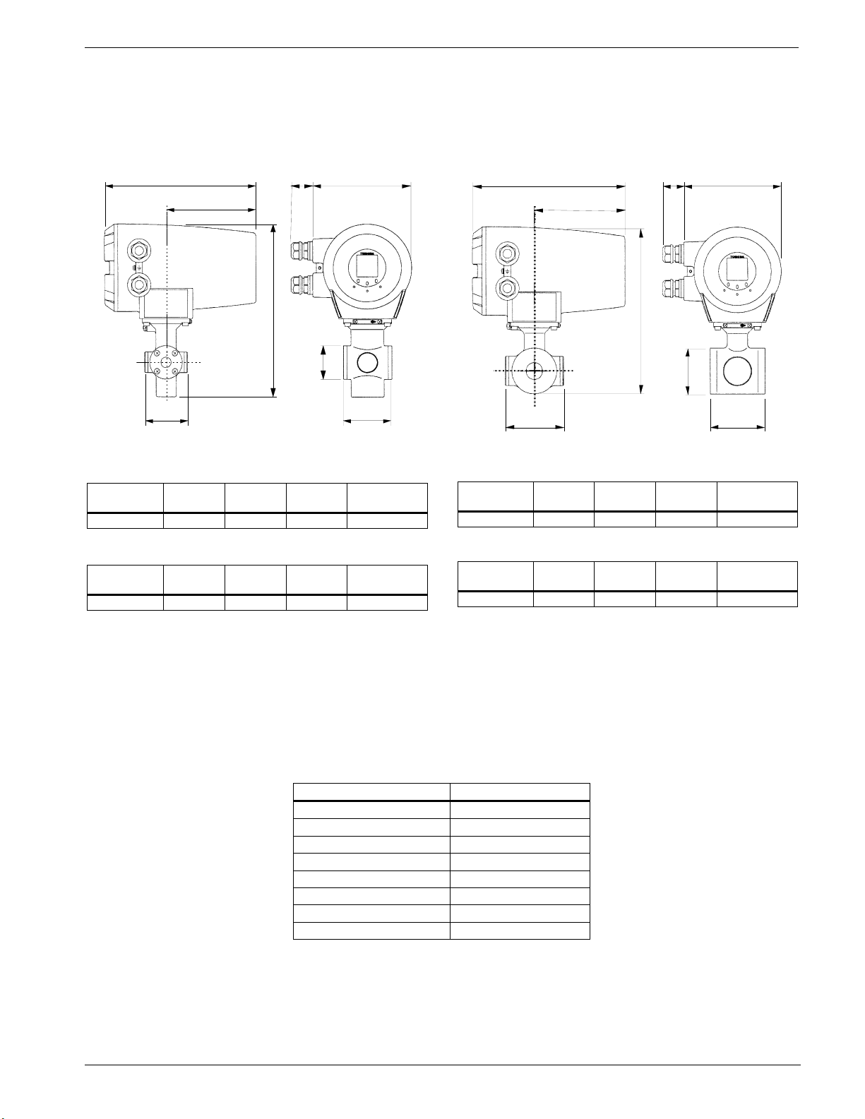
Dimensions
Unit : inch( mm)
8.86(225)
2. 5 2(64
5.16(131)
ANSI class 150 and class 300 dimensions:
Meter size
(inch)
1/2 2.76 9.92 1.93 approx. 11
L1
(inch)
L2
(inch)
BS16, DIN PN16 and JIS 10K dimensions:
Meter size
(mm)
15 70 252 49 approx. 5
Note: 1 inch = 25.4mm
L1
(mm)
L2
(mm)
Figure 3. LF410/LF610 and LF414/LF610F
flowmeters
Meter size 1/2"(15mm)
36)
1.42
(L2)
(inch)
(mm)
D1
D1
5.63(143)
ΦD1
L1
Weight
(lb)
Weight
(kg)
The dimension of L1 is changed when the material of
grounding ring is chosen Pt-Ir or Ta.
Meter size L1
1/2”(15mm) 3.03 inch(77mm)
1”(25mm) 3.74 inch(95mm)
1 1/2”(40mm) 4.53 inch(115mm)
2”(50mm) 4.96 inch(126mm)
3”(80mm) 4.96 inch(126mm)
4”(100mm) 5.35 inch(136mm)
6”(150mm) 9.53 inch(242mm)
8”(200mm) 12.28 inch(312mm)
Unit : inch( mm)
ANSI class 150 and class 300 dimensions:
Meter size
(inch)
1 3.15 9.48 2.60 approx. 11
BS16, DIN PN16 and JIS 10K dimensions:
Meter size
(mm)
25 80 241 66 approx. 5
Note: 1 inch = 25.4mm
Figure 4. LF410/LF610 and LF414/LF610F
8.86(225)
5.16(131)
3.43(87)
L1
(inch)
L1
(mm)
L2
(inch)
L2
(mm)
flowmeters
Meter size 1"(25mm)
(L 2)
1.42
36)
ΦD1
D1
(inch)
D1
(mm)
5.63(143)
L1
Weight
Weight
(lb)
(kg)
5
 Loading...