

Page 1

Toshiba Personal Computer
TECRA S3
Maintenance Manual
TOSHIBA CORPORATION
File Number 960-532
[CONFIDENTIAL]
Page 2

Copyright
© 2005 by Toshiba Corporation. All rights reserved. Under the copyright laws, this manual
cannot be reproduced in any form without the prior written permission of Toshiba. No patent
liability is assumed with respect to the use of the information contained herein.
Toshiba Personal Computer TECRA S3 Maintenance Manual
First edition August 2005
Disclaimer
The information presented in this manual has been reviewed and validated for accuracy. The
included set of instructions and descriptions are accurate for the TECRA S3 at the time of
this manual's production. However, succeeding computers and manuals are subject to
change without notice. Therefore, Toshiba assumes no liability for damages incurred
directly or indirectly from errors, omissions, or discrepancies between any succeeding
product and this manual.
Trademarks
IBM is a registered trademark and IBM PC is a trademark of International Business
Machines Corporation.
Intel, Intel SpeedStep, Pentium and Centrino are trademarks or registered trademarks of Intel
Corporation or its subsidiaries in the United States and other countries/regions.
Windows and Microsoft are registered trademarks of Microsoft Corporation.
Photo CD is a trademark of Eastman Kodak.
Sonic RecordNow! is a registered trademark of Sonic Solutions.
Bluetooth is a trademark owned by its proprietor and used by TOSHIBA under license.
i.LINK is trademark and registered trademark of Sony Corporation.
OmniPass is the trademark of Softex Incorporated.
InterVideo and WinDVD are registered trademarks of InterVideo Inc.
WinDVD Creator is trademark of InterVideo Inc.
Other trademarks and registered trademarks not listed above may be used in this manual.
ii [CONFIDENTIAL] TECRA S3 Maintenance Manual (960-532)
Page 3

Preface
This maintenance manual describes how to perform hardware service maintenance for the
Toshiba Personal Computer TECRA S3.
The procedures described in this manual are intended to help service technicians isolate
faulty Field Replaceable Units (FRUs) and replace them in the field.
SAFETY PRECAUTIONS
Four types of messages are used in this manual to bring important information to your
attention. Each of these messages will be italicized and identified as shown below.
DANGER: “Danger” indicates the existence of a hazard that could result in death or
serious bodily injury, if the safety instruction is not observed.
WARNING: “Warning” indicates the existence of a hazard that could result in bodily
injury, if the safety instruction is not observed.
CAUTION: “Caution” indicates the existence of a hazard that could result in property
damage, if the safety instruction is not observed.
NOTE: “Note” contains general information that relates to your safe maintenance
service.
Improper repair of the computer may result in safety hazards. Toshiba requires service
technicians and authorized dealers or service providers to ensure the following safety
precautions are adhered to strictly.
Be sure to fasten screws securely with the right screwdriver. If a screw is not fully
fastened, it could come loose, creating a danger of a short circuit, which could cause
overheating, smoke or fire.
If you replace the battery pack or RTC battery, be sure to use only the same model
battery or an equivalent battery recommended by Toshiba. Installation of the wrong
battery can cause the battery to explode.
TECRA S3 Maintenance Manual (960-532) [CONFIDENTIAL] iii
Page 4

The manual is divided into the following parts:
Chapter 1 Hardware Overview describes the TECRA S3 system unit and each
FRU.
Chapter 2 Troubleshooting Procedures explains how to diagnose and resolve
FRU problems.
Chapter 3 Test and Diagnostics describes how to perform test and diagnostic
operations for maintenance service.
Chapter 4 Replacement Procedures describes the removal and replacement of the
FRUs.
Appendices The appendices describe the following:
Handling the LCD module
Board layout
Pin assignments
Keyboard scan/character codes
Key layout
Wiring diagrams
BIOS rewrite procedures
EC/KBC rewrite procedures
Reliability
Maintenance of TOSHIBA RAID
iv [CONFIDENTIAL] TECRA S3 Maintenance Manual (960-532)
Page 5

Conventions
This manual uses the following formats to describe, identify, and highlight terms and
operating procedures.
Acronyms
On the first appearance and whenever necessary for clarification acronyms are enclosed in
parentheses following their definition. For example:
Read Only Memory (ROM)
Keys
Keys are used in the text to describe many operations. The key top symbol as it appears on
the keyboard is printed in boldface type.
Key operation
Some operations require you to simultaneously use two or more keys. We identify such
operations by the key top symbols separated by a plus (+) sign. For example, Ctrl + Pause
(Break) means you must hold down Ctrl and at the same time press Pause (Break). If
three keys are used, hold down the first two and at the same time press the third.
User input
Text that you are instructed to type in is shown in the boldface type below:
DISKCOPY A: B:
The display
Text generated by the computer that appears on its display is presented in the type face
below:
Format complete
System transferred
TECRA S3 Maintenance Manual (960-532) [CONFIDENTIAL] v
Page 6

Table of Contents
Chapter 1 Hardware Overview
1.1 Features......................................................................................................................1-1
1.2 2.5-inch Hard Disk Drive......................................................................................... 1-11
1.3 Keyboard..................................................................................................................1-13
1.4 Optical Drive............................................................................................................ 1-14
1.5 TFT Color Display...................................................................................................1-16
1.6 Power Supply...........................................................................................................1-18
1.7 Batteries ...................................................................................................................1-20
1.8 AC Adapter.............................................................................................................. 1-22
Chapter 2 Troubleshooting Procedures
2.1 Troubleshooting.........................................................................................................2-1
2.2 Troubleshooting Flowchart........................................................................................2-2
2.3 Power Supply Troubleshooting..................................................................................2-6
2.4 System Board Troubleshooting................................................................................2-15
2.5 USB FDD Troubleshooting .....................................................................................2-38
2.6 HDD Troubleshooting ............................................................................................. 2-41
2.7 Keyboard/Touch pad Troubleshooting.................................................................... 2-46
2.8 Display Troubleshooting..........................................................................................2-48
2.9 Optical Drive Troubleshooting................................................................................ 2-50
2.10 Modem Troubleshooting.......................................................................................... 2-51
2.11 LAN Troubleshooting..............................................................................................2-53
2.12 Sound Troubleshooting............................................................................................2-54
2.13 SD Card Slot Troubleshooting................................................................................. 2-57
2.14 Wireless LAN Troubleshooting...............................................................................2-58
2.15 Bluetooth Troubleshooting ......................................................................................2-60
2.16 PCI ExpressCard slot...............................................................................................2-63
2.17 Fingerprint sensor ....................................................................................................2-64
vi [CONFIDENTIAL] TECRA S3 Maintenance Manual (960-532)
Page 7

Chapter 3 Tests and Diagnostics
3.1 The Diagnostic Test...................................................................................................3-1
3.2 Executing the Diagnostic Test................................................................................... 3-4
3.3 Check of the RAID configuration..............................................................................3-9
3.4 Setting of the hardware configuration .....................................................................3-17
3.5 Heatrun Test.............................................................................................................3-20
3.6 Subtest Names.......................................................................................................... 3-21
3.7 System Test.............................................................................................................. 3-23
3.8 Memory Test............................................................................................................ 3-25
3.9 Keyboard Test.......................................................................................................... 3-26
3.10 Display Test.............................................................................................................3-27
3.11 Floppy Disk Test......................................................................................................3-30
3.12 Printer Test...............................................................................................................3-32
3.13 Async Test ...............................................................................................................3-34
3.14 Hard Disk Test......................................................................................................... 3-35
3.15 Real Timer Test........................................................................................................3-38
3.16 NDP Test..................................................................................................................3-40
3.17 Expansion Test.........................................................................................................3-41
3.18 CD-ROM/DVD-ROM Test .....................................................................................3-43
3.19 Error Code and Error Status Names.........................................................................3-44
3.20 Hard Disk Test Detail Status ................................................................................... 3-47
3.21 ONLY ONE TEST................................................................................................... 3-49
3.22 Head Cleaning.......................................................................................................... 3-59
3.23 Log Utilities.............................................................................................................3-60
3.24 Running Test............................................................................................................ 3-62
3.25 Floppy Disk Drive Utilities......................................................................................3-63
3.26 System Configuration ..............................................................................................3-68
3.27 Wireless LAN Test Program (Intel-made b/g).........................................................3-70
3.28 Wireless LAN Test Program (Intel-made a/g).........................................................3-74
3.29 LAN/Modem/Bluetooth/IEEE1394 Test Program ..................................................3-79
3.30 Sound Test program................................................................................................. 3-94
3.31 SETUP ...................................................................................................................3-100
TECRA S3 Maintenance Manual (960-532) [CONFIDENTIAL] vii
Page 8

Chapter 4 Replacement Procedures
4.1 General....................................................................................................................... 4-1
4.2 Battery pack............................................................................................................... 4-8
4.3 PC card.....................................................................................................................4-10
4.4 SD card.....................................................................................................................4-11
4.5 Memory module.......................................................................................................4-12
4.6 HDD......................................................................................................................... 4-14
4.7 Wireless LAN card .................................................................................................. 4-17
4.8 Slim select bay module............................................................................................4-19
4.9 Keyboard..................................................................................................................4-22
4.10 Touch pad.................................................................................................................4-25
4.11 Bluetooth module.....................................................................................................4-27
4.12 Switch membrane.....................................................................................................4-29
4.13 Display assembly.....................................................................................................4-31
4.14 RTC battery.............................................................................................................. 4-35
4.15 Modem Daughter Card (MDC)................................................................................4-36
4.16 USB board................................................................................................................ 4-39
4.17 Internal microphone.................................................................................................4-41
4.18 SR board/DC-IN jack...............................................................................................4-43
4.19 Fan............................................................................................................................4-45
4.20 CPU..........................................................................................................................4-47
4.21 GFX board ...............................................................................................................4-50
4.22 System board............................................................................................................ 4-52
4.23 FP board...................................................................................................................4-56
4.24 LCD unit/FL inverter...............................................................................................4-58
4.25 Cover latch...............................................................................................................4-65
4.26 Wireless LAN antenna/Bluetooth antenna...............................................................4-66
4.27 Hinge........................................................................................................................4-68
4.28 Speaker..................................................................................................................... 4-72
4.29 Battery slider............................................................................................................ 4-73
4.30 Fluorescent Lamp.....................................................................................................4-75
Appendices
viii [CONFIDENTIAL] TECRA S3 Maintenance Manual (960-532)
Page 9

Appendix A Handling the LCD Module ........................................................................... A-1
Appendix B Board Layout ................................................................................................ B-1
Appendix C Pin Assignments............................................................................................ C-1
Appendix D Keyboard Scan/Character Codes .................................................................. D-1
Appendix E Key Layout.....................................................................................................E-1
Appendix F Wiring Diagrams............................................................................................F-1
Appendix G BIOS rewrite Procedures .............................................................................. G-1
Appendix H EC/KBC rewrite Procedures......................................................................... H-1
Appendix I Reliability........................................................................................................I-1
Appendix J Maintenance of TOSHIBA RAID ..................................................................J-1
TECRA S3 Maintenance Manual (960-532) [CONFIDENTIAL] ix
Page 10

x [CONFIDENTIAL] TECRA S3 Maintenance Manual (960-532)
Page 11

Chapter 1
Hardware Overview
[CONFIDENTIAL]
Page 12

1 Hardware Overview
1-ii [CONFIDENTIAL] TECRA S3 Maintenance Manual (960-532)
Page 13

1 Hardware Overview
Chapter 1 Contents
1.1 Features.......................................................................................................................1-1
1.2 2.5-inch Hard Disk Drive.........................................................................................1-11
1.3 Keyboard ..................................................................................................................1-13
1.4 Optical Drive............................................................................................................1-14
1.4.1 DVD-ROM & CD-R/RW Drive.........................................................1-14
1.4.2 DVD Super Multi (DVD±R/±RW/-RAM) Drive...............................1-15
1.5 TFT Color Display ...................................................................................................1-16
1.5.1 LCD Module.......................................................................................1-16
1.5.2 FL Inverter Board ...............................................................................1-17
1.6 Power Supply............................................................................................................1-18
1.7 Batteries....................................................................................................................1-20
1.7.1 Main Battery .......................................................................................1-20
1.7.2 RTC battery.........................................................................................1-21
1.8 AC Adapter...............................................................................................................1-22
TECRA S3 Maintenance Manual (960-532) [CONFIDENTIAL] 1-iii
Page 14

1 Hardware Overview
Figures
Figure 1-1 Front of the computer .....................................................................................1-5
Figure 1-2 System unit configuration...............................................................................1-6
Figure 1-3 System unit block diagram .............................................................................1-7
Figure 1-4 2.5-inch HDD ...............................................................................................1-11
Figure 1-5 Keyboard ......................................................................................................1-13
Figure 1-6 LCD module .................................................................................................1-16
Tables
Table 1-1 2.5-inch HDD specifications ........................................................................1-11
Table 1-2 DVD-ROM & CD-R/RW drive specifications.............................................1-14
Table 1-3 DVD Super Multi (DVD±R/±RW/-RAM) drive specifications...................1-15
Table 1-4 LCD module specifications ..........................................................................1-16
Table 1-5 FL inverter board specifications...................................................................1-17
Table 1-6 Power supply output rating...........................................................................1-19
Table 1-7 Battery specifications ...................................................................................1-20
Table 1-8 Time required for charges of main battery...................................................1-20
Table 1-9 RTC battery charging/data preservation time...............................................1-21
Table 1-10 AC adapter specifications.............................................................................1-22
1-iv [CONFIDENTIAL] TECRA S3 Maintenance Manual (960-532)
Page 15

1 Hardware Overview
1 Features
1.1 Features
The Toshiba TECRA S3 Personal Computer uses extensive Large Scale Integration (LSI),
and Complementary Metal-Oxide Semiconductor (CMOS) technology extensively to provide
compact size, minimum weight, low power usage and high reliability. This computer
incorporates the following features and benefits:
Microprocessor
The PC comes in with one of the followings:
• • Intel Mobile Pentium-M Processor
1.73GHz/1.86GHz/2.0AGHz (0.748-1.356V)/2.13GHz (0.748-1.372V)
/2.26GHz (0.748-1.404V)
These processors operate at 533MHz bus clock.
Cache memory
Intel Mobile Pentium-M Processor has 64KB primary cache and 2MB secondary cache.
Memory
The computer comes with two PC2-3200/PC2-4200 compatible DDR2 SO-DIMM slots.
Two memory modules of 256GB, 512MB or 1GB(1,024MB) can be installed.
Video Controller
The computer has a NV43 VGA controller. The internal VRAM is 64MB or 128MB.
HDD
The computer has a 2.5-inch, 9.5mm SATA HDD. The following capacities are available.
40/60/80/100GB
USB FDD
Supports a USB 3.5-inch FDD, which connected via a USB port, supports 720KB,
1.2MB and 1.44MB formats and enables booting from system FD.
Batteries
The RTC battery (NiMH 2.4V 16mAh) is mounted inside the computer.
The main battery is a detachable lithium-ion main battery (10.8V-4,700mAh/8,800mAh) .
Universal Serial Bus (USB2.0)
Three USB ports are provided. The ports comply with the USB2.0 standard.
TECRA S3 Maintenance Manual (960-532) [CONFIDENTIAL] 1-1
Page 16

1 Hardware Overview
Display
LCD
The PC comes in with one of the following two types:
•
15.0” XGA-TFT color display, resolution 1,024×768, 16M colors
•
15.0” SXGA+-TFT color display, resolution 1,400×1,050, 16M colors
External monitor
Supported via a RGB connector.
Slim Select Bay
A DVD-ROM & CD-R/RW drive, DVD Super Multi drive (DVD±R/±RW/-RAM) or
2nd HDD can be installed in the Slim Select Bay.
Keyboard
An-easy-to-use 85-key (US) or 86-key (UK) keyboard provides a numeric keypad
overlay for fast numeric data entry or for cursor and page control. The keyboard supports
a Windows key and an application key.
Touch pad
Touch pad (dual point) is installed as a pointing device.
PC card slot
The PC card slot (PCMCIA) accommodates one 5mm Type II card. (Based on PC Card
Standard, supporting CardBus)
SD Card
The SD Card Slot can accommodate Secure Digital flash memory cards with various
capacities. SD cards let you easily transfer data from devices, such as digital cameras and
Personal Digital Assistants, which use SD Card flash-memory.
Sound system
The sound system is equipped with the following features:
•
Stereo speakers
•
Built-in microphone
•
Stereo headphone jack
•
External microphone jack
•
Supports VoIP
1-2 [CONFIDENTIAL] TECRA S3 Maintenance Manual (960-532)
Page 17

1 Hardware Overview
Toshiba Assist button
When this button is pressed during power-on, the PC is connected to “Toshiba Assist”.
When this button is pressed during power-off, the PC is turned on and connected to
“Toshiba Assist”.
Toshiba Presentation button
This button switches the display between internal display, external display, simultaneous
display and multi-monitor display.
Internal modem
The internal modem is equipped as a modem daughter card (MDC).
The internal modem provides capability for data and fax communication and supports
V.90/92. For data reception it operates at 56,000bps and for data transmission it operates
at 33,600bps. For fax transmission it operates at 14,400bps. It is also equipped with
Speakerphone and TAM (Telephony Answering Machine) function. The speed of data
transfer and fax depends on analog telephone line conditions. It has a RJ11 modem jack
for connecting to a telephone line.
Internal LAN
The computer is equipped with LAN circuits that support 1,000Mbit (Gigabit) Ethernet
LAN. It also supports Wakeup on LAN (WOL), Magic Packet and LED.
Mini PCI card slot (Wireless LAN)
The computer is equipped with a mini-PCI Type III wireless LAN card that supports
802.11 b/g or 802.11a/b/g (Intel made Freeville). It also supports kill switch.
Bluetooth
Bluetooth module can be equipped. This enables a communication to devices that support
Bluetooth Version 2.0. Adopting AFH (Adaptive Frequency Hopping), reduce the
interference with the wireless communication in 2.4GHz.
IEEE 1394 port
The computer comes with one IEEE 1394 port. It enables high-speed data transfer
directly from external devices such as digital video cameras.
Infrared port
The infrared port is compatible with Fast InfraRed (FIR) standards enabling cableless 4
Mbps (max.) data transfer with Infrared Data Association (IrDA) 1.1 compatible external
devices.
TECRA S3 Maintenance Manual (960-532) [CONFIDENTIAL] 1-3
Page 18

1 Hardware Overview
Fingerprint sensor
The computer is equipped with a fingerprint sensor and fingerprint authentication utility.
They enable only person who has registered his/her fingerprint to use the computer.
1-4 [CONFIDENTIAL] TECRA S3 Maintenance Manual (960-532)
Page 19
1 Hardware Overview
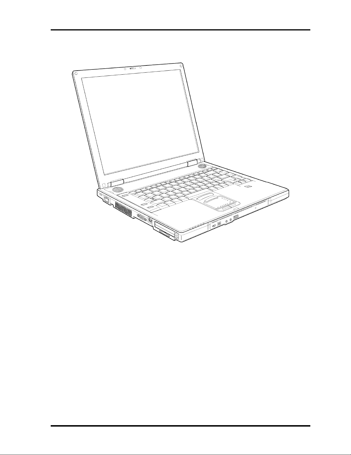
The front of the computer is shown in figure 1-1.
Figure 1-1 Front of the computer
TECRA S3 Maintenance Manual (960-532) [CONFIDENTIAL] 1-5
Page 20
1 Hardware Overview
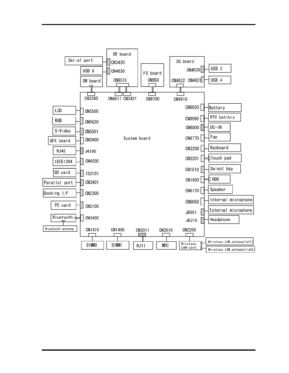
The system unit configuration is shown in figure 1-2.
Figure 1-2 System unit configuration
1-6 [CONFIDENTIAL] TECRA S3 Maintenance Manual (960-532)
Page 21
1 Hardware Overview
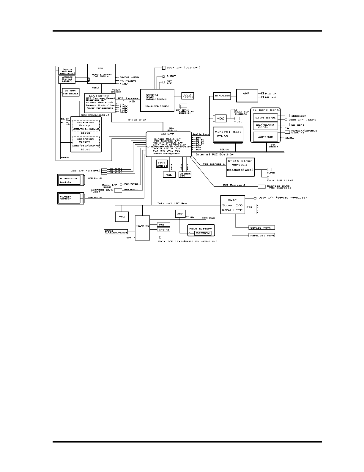
Figure 1-3 is a block diagram of the system unit.
Figure 1-3 System unit block diagram
TECRA S3 Maintenance Manual (960-532) [CONFIDENTIAL] 1-7
Page 22

1 Hardware Overview
The system unit is composed of the following major components:
Processor
• Intel Mobile Pentium-M Processor
– Processor core speed: 1.73GHz/1.86GHz/2.0AGHz/2.13GHz/2.26GHz
– Processor bus speed: 533MHz
– Integrated L1 cache memory: 32KB instruction cache and 32KB write-back
data cache
– Integrated L2 cache memory: 2MB
– Integrated NDP
Memory
Two memory slots are provided. Expansion up to 2GB (2,048MB) is available.
Memory
• DDR2-SDRAM
• DDR400 or DDR533 memory
• 1.8 volt operation
• FBGA
Memory Module
• 240 pin, SO Dual In-line Memory Module (SO-DIMM)
• PC2-3200 or PC2-4200
• 256MB/512MB/1GB
– 256 MB 256Mb×8
– 512 MB 512Mb×8
– 1GB 512Mb×16
Firmware Hub (FWH)
• One STMicro M50FW080N is used.
• 8Mbits of flash memory are used.
PCI chipset
This gate array incorporates the following elements and functions.
• North Bridge (Intel GMCH, AlvisoPM)
– Dothan Processor System Bus Support
– System memory interface
– DRAM Controller: DDR333, DDR2-400/DDR2-533 Support, 2GB max
– X16 PCI Express Graphics Interface
– DMI (Direct Media Interface)
– 1257-ball, 40.0×40.0 mm, FC-BGA package
1-8 [CONFIDENTIAL] TECRA S3 Maintenance Manual (960-532)
Page 23

1 Hardware Overview
• South Bridge (Intel ICH6)
– DMI (Direct Media Interface)
– PCI Express 2 Interface (4ports)
– PCI Bus Rev2.3 Interface (7 PCI REQ/GNT Pairs)
– Integrated Serial ATA Host Controller (2ports, 150MB/S)
– Integrated IDE Controller (Ultra ATA 100/66/33)
– AC'97 2.3 Interface
– USB 1.1/2.0 Controller 8 Ports (EHCI: Enhanced Host Controller)
– Internal LAN Controller (WfM 2.0 and IEEE 802.3)
– Power Management Controller (ACPI 2.0)
– SMBus2.0 Controller
– FWH Interface
– LPC Interface (EC/KBC, Super I/O)
– IRQ Controller
– Serial Interrupt Controller
– Suspend/Resume Control
– Internal RTC
– GPIO
– 609-ball, 31.0×31.0mm, BGA Package
PC Card Controller
• One TI PC7411ZHK gate array is used.
• This gate array has the following functions and components.
– PCI interface
– CardBus/Ultra Media (1 socket)
– SD/MMC, Memory Stick, XD Card Controller
– 1394 Controller (2 ports)
– 208-ball, 16.0×16.0×1.4mm, BGA Package
Other main system chips
• Clock Generator (ICS950812CG)
• Super I/O (SMSC Kona-Life)
• EC/KBC (Mitsubishi M306KA)
• PSC (TOSHIBA TMP87PM48U)
• LCD Sensor (NRS-701-1015T)
• Thermal Sensor (ADM1032×2)
• AXIS accelerometer (STMicro LIS3L02AQ)
Modem Controller
Supported by Azallia MDC 1.5 using the Azallia link.
TECRA S3 Maintenance Manual (960-532) [CONFIDENTIAL] 1-9
Page 24

1 Hardware Overview
Internal LAN Controller (Marvell maid)
Controls LAN and supports Gigabit Ethernet.
Gigabit is connected to PCI-Express.
Sound Controller
Azallia and CODEC (STAC9200) are used.
1-10 [CONFIDENTIAL] TECRA S3 Maintenance Manual (960-532)
Page 25
1 Hardware Overview
1.2 2.5-inch Hard Disk Drive
The HDD is a random access non-volatile storage device. The computer supports a 40GB,
60GB, 80GB and 100GB HDD.
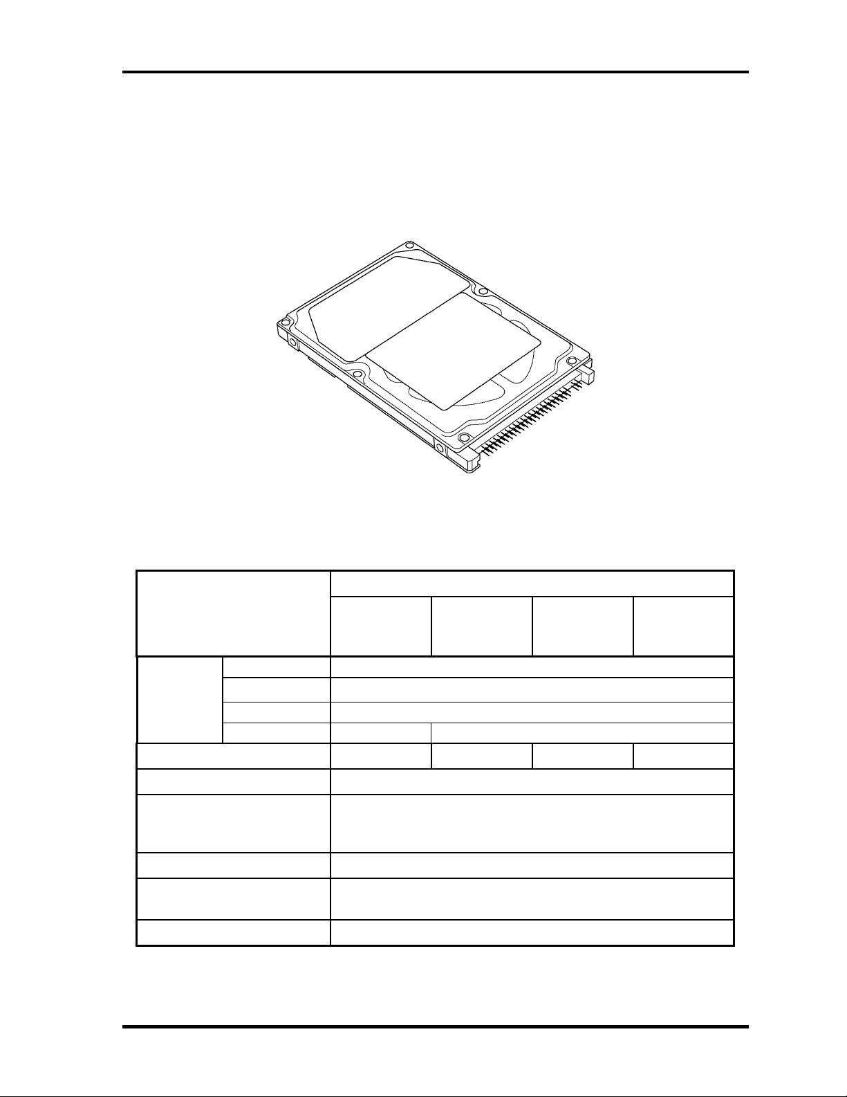
The HDD is shown in figure 1-4. Specifications are listed in Table 1-1.
Figure 1-4 2.5-inch HDD
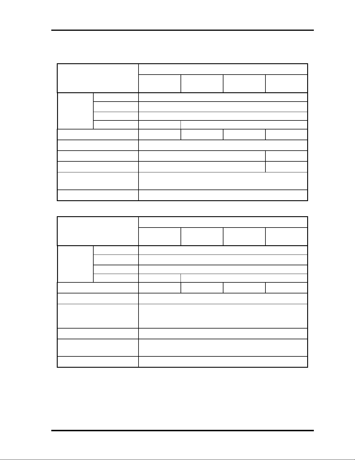
Table 1-1 2.5-inch HDD specifications (1/2)
Specifications
Items
Outline
dimensions
Storage size (formatted) 40GB 60GB 80GB 100GB
Speed (RPM) 5,400
Data transfer rate
To/From media (MB/s)
To/From host (Gbps)
Data buffer size (MB) 8
Width (mm)
Height (mm)
Depth (mm)
Weight (g)
FUJITSU
G8BC00028410
96 max. 101 max.
FUJITSU
G8BC00028610
70
9.5
100
64.0 max.
1.5 (150 MB/s) max.
FUJITSU
G8BC00028810
FUJITSU
G8BC00028A1
0
Average seek time
Read (ms)
Motor startup time (s) 4 typ.
12 typ.
TECRA S3 Maintenance Manual (960-532) [CONFIDENTIAL] 1-11
Page 26
1 Hardware Overview
Table 1-1 2.5-inch HDD specifications (2/2)
Items Specifications
Outline
dimensions
Width (mm)
Height (mm)
Depth (mm)
Weight (g)
TOSHIBA
HDD2D34BZK01
TOSHIBA
HDD2D33BZK01
TOSHIBA
HDD2D32BZK01
69.85
9.5
100
98 max. 102 max.
TOSHIBA
HDD2D30BZK01
Storage size (formatted) 40GB 60GB 80GB 100GB
Speed (RPM) 5,400
Data transfer rate (Mb/s) 218-429 236.1-456.0
Data buffer size (kb) 8,192 16,384
Average seek time
Read (ms)
12
Motor startup time (s) 4
Items Specifications
Outline
dimensions
Width (mm)
Height (mm)
Depth (mm)
Weight (g)
Storage size (formatted) 40GB 60GB 80GB 100GB
HITACH GST
G8BC00029410
HITACH GST
G8BC00029610
HITACH GST
G8BC00029810
69.85±0.25
9.5±0.2
100.2±0.25
95 max. 102 max.
HITACH GST
G8BC00029A10
Speed (RPM) 5,400
Data transfer rate
To/From media (Mb/s)
To/From host (Gbps)
493 max.
1.5
Data buffer size (MB) 8
Average seek time
Read (ms)
12 typ.
Motor startup time (s) 3.5
1-12 [CONFIDENTIAL] TECRA S3 Maintenance Manual (960-532)
Page 27

1 Hardware Overview
1.3 Keyboard
The keyboard is mounted 85(US)/86(UK) keys that consist of character key and control key.
The keyboard is connected to membrane connector on the system board and controlled by the
keyboard controller.
Figure 1-5 is a view of the keyboard.
See Appendix E about a layout of the keyboard.
Figure 1-5 Keyboard
TECRA S3 Maintenance Manual (960-532) [CONFIDENTIAL] 1-13
Page 28

1 Hardware Overview
1.4 Optical Drive
1.4.1 DVD-ROM & CD-R/RW Drive
The DVD-ROM & CD-R/RW drive accommodates either 12 cm (4.72-inch) or 8 cm (3.15inch) CDs, CD-R/RW and DVDs. It is a high-performance drive that writes CD-R at
maximum 24-speed and CD-RW at maximum 24-speed (Ultra Speed CD-RW) and reads
DVD-ROM at maximum 8-speed and CD-ROM at maximum 24-speed.
DVD-ROM & CD-R/RW drive specifications are listed in Table 1-2.
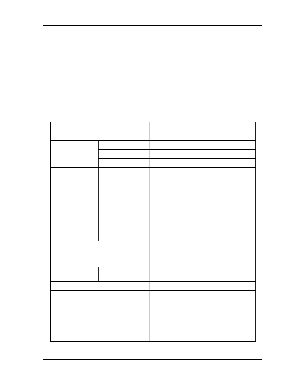
Table 1-2 DVD-ROM & CD-R/RW drive specifications
Item
MATSUSHITA G8CC00025A20
Outline Width (mm) 128 (The projection part is excluded)
Dimensions Height (mm) 9.5 (The projection part is excluded)
Depth (mm) 129 (The projection part is excluded)
Date transfer speed
READ
Write CD-R
ATAPI Burst (MB/s)
PIO Mode
DMA Mode
Ultra DMA Mode
Average access time
(msec)
Data Buffer Capacity 2MB
Supported Disks CD: CD/CD-ROM (12cm, 8cm), CD-R,
DVD-ROM
CD-ROM
CD-RW
High Speed CD-RW
Ultra Speed CD-RW
CD-ROM
DVD-ROM
CD-RW
Specifications
Max. 8x CAV
Max. 24x CAV
Max. 24x CAV
Max. 4x CLV
Max. 10x CLV
Max. 24x CAV
16.6 (PIO MODE4)
16.6 (Multi Word Mode2)
33.3 (Ultra DMA Mode2)
150 typ.
170 typ.
DVD:DVD-ROM, DVD-R, DVD-RW, DVD+R,
DVD+RW, DVD+RAM, DVD+R DL
Supported Formats CD: CD-DA, CD-ROM, CD-ROM XA,
PHOTO CD, CD-Extra(CD+), CD-text
DVD:DVD-R, DVD-RW (Ver.1.2), DVD-Video,
DVD+R, DVD+RW,
DVD-RAM (2.6GB/4.7GB)
1-14 [CONFIDENTIAL] TECRA S3 Maintenance Manual (960-532)
Page 29
1 Hardware Overview
1.4.2 DVD Super Multi (DVD±R/±RW/-RAM) Drive
The DVD Super Multi drive is capable of driving either 12cm (4.72-inch) or 8cm (3.15-inch)
DVD and CD without using an adaptor. This drive reads DVD-ROM at maximum 8-speed,
reads CD-ROM at maximum 24-speed, writes CD-R at maximum 24-speed, writes CD-RW
at maximum 10-speed, writes DVD-R at maximum 4-speed, writes DVD-RW at maximum 2speed, writes DVD+R at maximum 4-speed, writes DVD+R DL at maximum 2.4-speed,
writes DVD+RW at maximum 2.4-speed and writes DVD-RAM at maximum 2-speed.
The DVD Multi drive specifications are listed in Table 1-3.
Table 1-3 DVD Super Multi (DVD±R/±RW/-RAM) drive specifications
Item
MATSUSHITA G8CC0002Q120
Outline Width (mm) 128 (The projection part is excluded)
Dimensions Height (mm) 9.5 (The projection part is excluded)
Depth (mm) 129 (The projection part is excluded)
Date transfer speed
READ
Write CD-R
ATAPI Burst (MB/s)
PIO Mode
DMA Mode
Ultra DMA Mode
DVD-ROM
CD-ROM
CD-RW
High Speed CD-RW
Ultra Speed CD-RW
DVD-R
DVD-RW
DVD+R
DVD+R DL
DVD+RW
DVD-RAM
Specifications
Max. 8x CAV
Max. 24x CAV
Max. 24x ZCLV
Max. 4x CLV
Max. 10x CLV
Max. 10x CLV
Max. 4x ZCLV
Max. 2x CLV
Max. 4x ZCLV
Max. 2.4x CLV
Max. 2.4x CLV
Max. 2x ZCLV
16.6 (PIO MODE4)
16.6 (Multi Word Mode2)
33.3 (Ultra DMA Mode2)
Average access
time (msec)
Data Buffer Capacity 2MB
Supported Formats CD: CD-DA, CD-ROM, CD-R, CD-RW, CD-
CD-ROM
DVD-ROM
150 typ.
180 typ.
ROM XA, PHOTO CD, Video CD,
CD-Extra(CD+), CD-text
DVD:DVD-VIDEO, DVD-ROM,
DVD-R(3.9GB/4.7GB),
DVD-RW(Ver. 1.1),
DVD-RAM(2.6GB/4.7GB/9.4GB),
DVD+R, DVD+R DL, DVD+RW
TECRA S3 Maintenance Manual (960-532) [CONFIDENTIAL] 1-15
Page 30
1 Hardware Overview
1.5 TFT Color Display
The TFT color display consists of 15.0-inch XGA/SXGA+ LCD module and FL inverter
board.
1.5.1 LCD Module
The LCD module used for the TFT color display uses a backlight as the light source and can
display a maximum of 16M colors with 1,024 x 768 or 1,400x 1,050 resolution. The
NVIDIA-made NV43 can control both internal and external XGA/SXGA+ support displays
simultaneously.
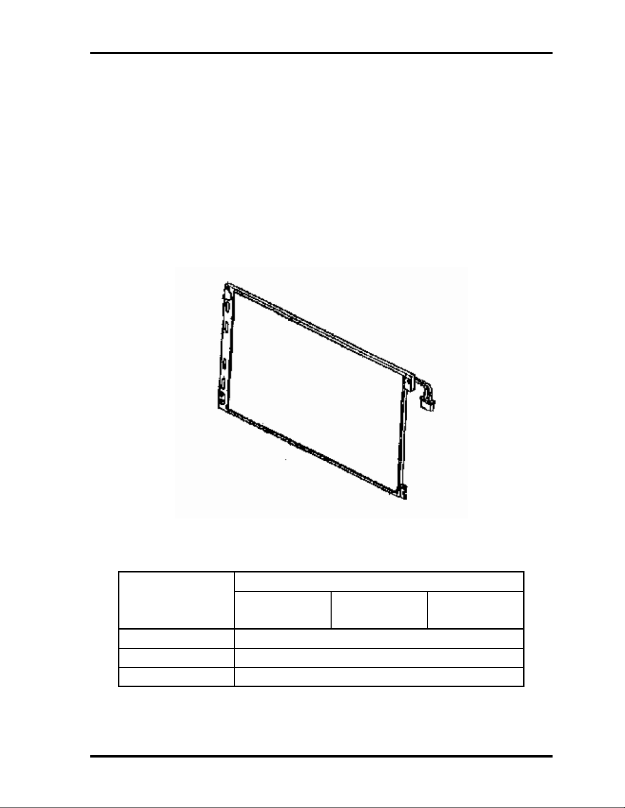
Figure 1-6 shows a view of the LCD module and Table 1-4 lists the specifications.
Figure 1-6 LCD module
Table 1-4 LCD module specifications (1/2)
Specifications (15.0-inch XGA TFT)
Item
Number of Dots
Dot spacing (mm) 0.297(H) × 0.297(V)
Display range (mm) 304.128(H) × 228.096(V)
1-16 [CONFIDENTIAL] TECRA S3 Maintenance Manual (960-532)
LG Philips
G33C00030110
SHARP
G33C0002Y110
1,024(W) × 768(H)
Samsung
G33C0002W110
Page 31

1 Hardware Overview
Table 1-4 LCD module specifications (2/2)
Item
Number of Dots 1,400(W) x 1,050 (H)
Dot spacing (mm) 0.2175 (H) x 0.2175 (V)
Display range (mm) 304.5 (W) x 228.38 (H)
Specifications (15.0-inch SXGA+ TFT)
LG Philips G33C0001X210
1.5.2 FL Inverter Board
The FL inverter board supplies a high frequency current to illuminate the LCD module FL.
Table 1-5 lists the FL inverter board specifications.
Table 1-5 FL inverter board specifications
Item Specifications
G71C00011221
Voltage (VDC) 5 Input
Power (W) 7
Output
Voltage (Vrms) 750
Current (mArms) 6.00
Power (W/VA) 5/7
TECRA S3 Maintenance Manual (960-532) [CONFIDENTIAL] 1-17
Page 32

1 Hardware Overview
1.6 Power Supply
The power supply supplies many different voltages to the system board and performs the
following functions:
1. Judges that the DC power supply (AC adapter) is connected to the computer.
2. Detects DC output and circuit malfunctions.
3. Controls the battery icon, and DC IN icon.
4. Turns the battery charging system on and off and detects a fully charged battery.
5. Turns the power supply on and off.
6. Provides more accurate detection of a low battery.
7. Calculates the remaining battery capacity.
8. Controls the transmission of the status signal of the main battery.
The power supply output rating is specified in Table 1-6.
1-18 [CONFIDENTIAL] TECRA S3 Maintenance Manual (960-532)
Page 33

1 Hardware Overview
Table 1-6 Power supply output rating
Name Voltage (V) Use
PPV
PTV
PGV
1R5-P1V
1R8-B1V
VG1R8-P1V
2R5-P2V
MR0R9-B0V
0R9-P0V
P3V
E3V
SD-E3V 3.3 SD Card
LAN-E3V 3.3 LAN Power
LAN2R5-E2V 2.5 LAN Power
1.404-0.748 CPU
1.05
1.056
1.5
1.8
1.8
2.5
0.9
0.9
3.3
3.3
CPU, MCH, ICH6-M
GPU
CPU, MCH, ICH6-M, Express Card
MCH, DDR2-SDRAM
GPU
MCH, ICH6-M
MCH, DDR2-SDRAM
DDR2-SDRAM
Clock Generator, Thermal Sensor, SDRAM(SPD), ICH6-
M,Super I/O, GPU, Mini-PCI, TPM, LCD, Express Card,
FWH, FIR, STAC9200, HDD (SATA), Finger Print Sensor
ICH6-M, TI CARD Cont., PC Card Power, Mini-PCI,
Express Card, MDC, RS-232C
BT-P3V 3.3 Bluetooth
USB0PS-E5V 5 USB
USB1PS-E5V 5 USB
S3V 3.3 EC/KBC, PSC, 3 AXIS Accerelometer
P5V 5
1R5-E1V 1.5 ICH6-M
SND-P5V 5 AN12941
A4R7-P4V 4.7 STAC9200, AN12941
E5V 5 ICH6-M, PC Card Power, USB Power
M5V 5 Docker, MAX6501, LED
MCV 5 PSC
R3V 2.0 - 3.5 ICH6-M(RTC)
CRT, ICH6-M, FL inverter, LEDs, HDD (SATA), ODD, KB,
PAD, Bluetooth Power, Parallel
TECRA S3 Maintenance Manual (960-532) [CONFIDENTIAL] 1-19
Page 34

1 Hardware Overview
1.7 Batteries
The computer has two types of batteries as follows:
Main battery pack
RTC battery
The battery specifications are listed in Table 1-7.
Table 1-7 Battery specifications
Battery name Material Output voltage Capacity
G71C0003W510
Main battery
RTC battery GDM710000041 NiMH 2.4 V 16 mAh
G71C0003W610
Lithium-Ion 10.8 V
G71C0004G510
G71C0004G610
8,800 mAh
4,700 mAh
1.7.1 Main Battery
The removable main battery pack is the computer’s main power source when the AC adaptor
is not attached. The main battery maintain the state of the computer when the computer
enters in resume mode.
θ Battery Charge
When the AC adapter is connected, normal charging is used while the system is turned on
and quick charge is used while the system is turned off or in suspend mode.
(See Table 1-8)
Table 1-8 Time required for charges of main battery
Power ON Power OFF
Battery (8,800mAh) About 5.0 to 21.5 hours About 4.5 hours
Battery (4,700mAh) About 3.5 to 13.0 hours About 3.0 hours
Charge is stopped in the following cases.
1. The main battery is fully charged.
2. The main battery is removed.
3. Main battery or AC adapter voltage is abnormal.
4. Charging current is abnormal.
1-20 [CONFIDENTIAL] TECRA S3 Maintenance Manual (960-532)
Page 35

1 Hardware Overview
1.7.2 RTC battery
The RTC battery provides power to keep the current date, time and other setup information
in memory while the computer is turned off. Table 1-9 lists the charging time and data
preservation period of the RTC battery.
Table 1-9 RTC battery charging/data preservation time
Status Time
Charging Time (power on) 8 hours
Data preservation period (full charge) 30 days
TECRA S3 Maintenance Manual (960-532) [CONFIDENTIAL] 1-21
Page 36

1 Hardware Overview
1.8 AC Adapter
The AC adapter is used to charge the battery.
Table 1-10 lists the AC adapter specifications.
Table 1-10 AC adapter specifications
Specification
Parameter
Voltage 75W (Peak 90W)
Input voltage 100V/240V
Input frequency 47Hz to 63Hz
Input power 1.5A or less (100V)
G71C00043310
(two-pins)
1.125A or less (240V)
G71C00049410
(three-pins)
Output voltage DC15V
Output current 0A to 5A (At constant voltage mode)
5A to 6A (At surge load mode)
1-22 [CONFIDENTIAL] TECRA S3 Maintenance Manual (960-532)
Page 37

Chapter 2
Troubleshooting Procedures
[CONFIDENTIAL]
Page 38

2 Troubleshooting Procedures
2-ii [CONFIDENTIAL] TECRA S3 Maintenance Manual (960-532)
Page 39

2 Troubleshooting Procedures
Chapter 2 Contents
2.1 Troubleshooting..........................................................................................................2-1
2.2 Troubleshooting Flowchart ........................................................................................2-2
2.3 Power Supply Troubleshooting..................................................................................2-6
Procedure 1 Icons in the LCD Check...............................................................2-6
Procedure 2 Error Code Check ........................................................................2-8
Procedure 3 Connection Check......................................................................2-13
Procedure 4 Charge Check.............................................................................2-13
Procedure 5 Replacement Check....................................................................2-14
2.4 System Board Troubleshooting................................................................................2-15
Procedure 1 Message Check ..........................................................................2-16
Procedure 2 Printer Port LED Check on Boot Mode.....................................2-18
Procedure 3 Printer Port LED Check on Suspend/Resume Mode .................2-29
Procedure 4 Diagnostic Test Program Execution Check ...............................2-37
Procedure 5 Replacement Check....................................................................2-37
2.5 USB FDD Troubleshooting......................................................................................2-38
Procedure 1 USB FDD Head Cleaning Check...............................................2-38
Procedure 2 Diagnostic Test Program Execution Check ...............................2-39
Procedure 3 Connector Check and Replacement Check................................2-40
2.6 HDD Troubleshooting..............................................................................................2-41
Procedure 1 Partition Check...........................................................................2-41
Procedure 2 Message Check ..........................................................................2-42
Procedure 3 Format Check.............................................................................2-43
Procedure 4 Diagnostic Test Program Execution Check ...............................2-44
Procedure 5 Connector Check and Replacement Check................................2-45
2.7 Keyboard/Touch pad Troubleshooting.....................................................................2-46
Procedure 1 Diagnostic Test Program Execution Check ...............................2-46
Procedure 2 Connector Check and Replacement Check................................2-46
TECRA S3 Maintenance Manual (960-532) [CONFIDENTIAL] 2-iii
Page 40

2 Troubleshooting Procedures
2.8 Display Troubleshooting..........................................................................................2-48
Procedure 1 Diagnostic Test Program Execution Check ...............................2-48
Procedure 2 Connector Check and Cable Check ...........................................2-48
Procedure 3 Replacement Check....................................................................2-49
2.9 Optical Drive Troubleshooting.................................................................................2-50
Procedure 1 Diagnostic Test Program Execution Check ...............................2-50
Procedure 2 Connector Check and Replacement Check................................2-50
2.10 Modem Troubleshooting ..........................................................................................2-51
Procedure 1 Diagnostic Test Program Execution Check ...............................2-51
Procedure 2 Connector Check and Replacement Check................................2-52
2.11 LAN Troubleshooting ..............................................................................................2-53
Procedure 1 Diagnostic Test Program Execution Check ...............................2-53
Procedure 2 Connector Check and Replacement Check................................2-53
2.12 Sound Troubleshooting ............................................................................................2-54
Procedure 1 Diagnostic Test Program Execution Check ...............................2-54
Procedure 2 Connector Check........................................................................2-55
Procedure 3 Replacement Check....................................................................2-56
2.13 SD Card Slot Troubleshooting .................................................................................2-57
Procedure 1 Check on Windows XP..............................................................2-57
Procedure 2 Connector Check and Replacement Check................................2-57
2.14 Wireless LAN Troubleshooting ...............................................................................2-58
Procedure 1 Transmitting-Receiving Check ..................................................2-58
Procedure 2 Antenna Connection Check .......................................................2-59
Procedure 3 Replacement Check....................................................................2-59
2.15 Bluetooth Troubleshooting.......................................................................................2-60
Procedure 1 Transmitting-Receiving Check ..................................................2-60
Procedure 2 Antenna Connection Check .......................................................2-61
Procedure 3 Replacement Check....................................................................2-62
2.16 PCI ExpressCard slot................................................................................................2-63
2-iv [CONFIDENTIAL] TECRA S3 Maintenance Manual (960-532)
Page 41

2 Troubleshooting Procedures
2.17 Fingerprint sensor.....................................................................................................2-64
Procedure 1 Setting Windows Log-ON password .........................................2-65
Procedure 2 Registration of fingerprint..........................................................2-65
Procedure 3 Authentication of fingerprint .....................................................2-69
Procedure 4 Connector Check and Replacement Check................................2-70
Figures
Figure 2-1 Troubleshooting flowchart ..................................................................................2-3
Figure 2-2 Printer port LED board......................................................................................2-18
Figure 2-3 Printer port LED board status............................................................................2-18
Tables
Table 2-1 Battery icon..........................................................................................................2-6
Table 2-2 DC IN icon...........................................................................................................2-7
Table 2-3 Error code ............................................................................................................2-8
Table 2-4 Printer port LED boot mode status....................................................................2-20
Table 2-5 Printer port LED suspend mode error status .....................................................2-30
Table 2-6 Printer port LED resume mode error status.......................................................2-33
Table 2-7 FDD error code and status.................................................................................2-39
Table 2-8 HDD error code and status ................................................................................2-44
TECRA S3 Maintenance Manual (960-532) [CONFIDENTIAL] 2-v
Page 42

2 Troubleshooting Procedures
2-vi [CONFIDENTIAL] TECRA S3 Maintenance Manual (960-532)
Page 43

2 Troubleshooting Procedures
2
2.1 Troubleshooting
Chapter 2 describes how to determine if a Field Replaceable Unit (FRU) in the computer is
causing the computer to malfunction. The FRUs covered are:
1. Power Supply 6. Display 11. SD Card Slot
2. System Board 7. Optical Drive 12. Wireless LAN
3. USB Floppy Disk Drive 8. Modem 13. Bluetooth
4. Hard Disk Drive 9. LAN 14. PCI ExpressCard
5. Keyboard/Touch pad 10. Sound 15. Fingerprint Sensor
The Diagnostics Disk operations are described in Chapter 3. Detailed Replacement
Procedures are given in Chapter 4, Replacement Procedures.
The following tools are necessary for implementing the troubleshooting procedures:
The following tools are necessary for implementing the Diagnostics pro cedu res:
For tools required for executing the Test Program, refer to the Chapter3. For tools required
for disassembling/assembling, refer to the Chapter 4.
1. Toshiba MS-DOS system FD
2. LED board
3. Headphone (for Sound troubleshooting)
4. An external microphone(for Sound troubleshooting)
5. A SD card (for SD card slot troubleshooting)
Formatted:
Numbered + Level: 1 +
Numbering Style: 1, 2, 3, … +
Start at: 1 + Alignment: Left +
Aligned at: 0 pt + Tab after: 18
pt + Indent at: 18 pt
Indent: Left: 18 pt,
TECRA S3 Maintenance Manual (960-532) [CONFIDENTIAL] 2-1
Page 44

2 Troubleshooting Procedures
2.2 Troubleshooting Flowchart
Use the flowchart in Figure 2-1 as a guide for determining which FRU malfunctions. Before
going through the flowchart steps, check the following:
Ask the user if a password is registered and if it is, ask him or her to enter the
password.
Make sure that Toshiba Windows
®
XP/ Windows® 2000 is installed on the hard disk.
Non-Toshiba operating systems can cause the computer malfunction.
Make sure all optional equipment is removed from the computer.
Make sure the USB FDD is empty.
Formatted:
Numbering Style: Bullet + Start at: 1 +
Alignment: Left + Aligned at: 18 pt +
Tab after: 0 pt + Indent at: 36 pt,
Tabs: 18 pt, Left
Numbered + Level: 1 +
2-2 [CONFIDENTIAL] TECRA S3 Maintenance Manual (960-532)
Page 45

2 Troubleshooting Procedures
Figure 2-1 Troubleshooting flowchart (1/2)
TECRA S3 Maintenance Manual (960-532) [CONFIDENTIAL] 2-3
Page 46

2 Troubleshooting Procedures
Figure 2-1 Troubleshooting flowchart (2/2)
2-4 [CONFIDENTIAL] TECRA S3 Maintenance Manual (960-532)
Page 47

2 Troubleshooting Procedures
If the diagnostics program cannot detect an error, the problem may be intermittent. The
Running Test program should be executed several times to isolate the problem. Check the
Log Utilities function to confirm which diagnostic test detected an error, then perform the
appropriate troubleshooting procedures as follows:
1. If an error is detected on the system test, memory test, real timer test, perform the
System Board Troubleshooting Procedures in Section 2.4.
2. If an error is detected on the floppy disk test, perform the USB FDD Troubleshooting
Procedures in Section 2.5.
3. If an error is detected on the hard disk test, perform the HDD Troubleshooting
Procedures in Section 2.6.
4. If an error is detected on the keyboard/touch pad test, per form the Keyboard
Troubleshooting Pr ocedures in Section 2.7.
5. If an error is detected on the display test, perform the Display Troubleshooting
Procedures in Section 2.8.
6. If an error is detected on the optical drive test, perform the Optical Drive
Troubleshooting Pr ocedures in Section 2.9.
7. If an error is detected on the modem test, perform the Modem Troubleshooting
Procedures in Section 2.10.
8. If an error is detected on the LAN test, perform the LAN Troubleshooting Procedures
in Section 2.11.
9. If an error is detected on the sound test, perform the Sound Troubleshooting
Procedures in Section 2.12.
Formatted:
+ Numbering Style: 1, 2, 3, … +
Start at: 1 + Alignment: Left +
Aligned at: 18 pt + Tab after: 0
pt + Indent at: 36 pt, Tabs: 18
pt, Left
Formatted:
+ Numbering Style: 1, 2, 3, … +
Start at: 1 + Alignment: Left +
Aligned at: 18 pt + Tab after: 0
pt + Indent at: 36 pt, Tabs: 18
pt, Left
Numbered + Level: 1
Numbered + Level: 1
10. If an error is detected on SD card slot, perform the SD Card Slot Troubleshooting
Procedures in Section 2.13.
11. If an error is detected on the Wireless LAN test, perform the Wire less LAN
Troubleshooting Pr ocedures in Section 2.14.
12. If an error is detected on the Bluetooth test, perform the Bluetooth Troubleshooting
Procedures in Section 2.15.
13. If a malfunction is detected on the PCI ExpressCard, perform the PCI ExpressCard
Troubleshooting Pr ocedures in Section 2.16.
14. If a malfunction is detected on the Fingerprint sensor, perform the Fingerprint Sensor
Troubleshooting Pr ocedures in Section 2.17.
TECRA S3 Maintenance Manual (960-532) [CONFIDENTIAL] 2-5
Page 48

2 Troubleshooting Procedures
2.3 Power Supply Troubleshooting
The power supply controls many functions and components. To determine if the power
supply is functioning properly, start with Procedure 1 and continue with the other Procedures
as instructed. The procedures described in this section are:
Procedure 1: Icons in the LCD Check
Procedure 2: Error Code Check
Procedure 3: Connection Check
Procedure 4: Charge Check
Procedure 5: Replacement Check
Procedure 1 Icons in the LCD Check
The following Icons in the LCD indicate the power supply status:
Battery icon
DC IN icon
The power supply controller displays the power supply status through the Battery icon and
the DC IN icon in the LCD as listed in the tables below. To check the power supply status,
install a battery pack and connect an AC adaptor.
Formatted:
Numbering Style: Bullet + Start at: 1 +
Alignment: Left + Aligned at: 18 pt +
Tab after: 0 pt + Indent at: 36 pt,
Tabs: 18 pt, Left
Numbered + Level: 1 +
Table 2-1 Battery icon
Battery icon Power supply status
Lights orange Battery has been charging and AC adapter is connected.
Lights green Battery is fully charged and AC adapter is connected.
Blinks orange
(even intervals)
Flashes orange Battery charge is low. AC adaptor must be connected to recharge the
Doesn’t light Any condition other than those above.
Battery charge is low while s ystem p o wer is ON.
battery.
2-6 [CONFIDENTIAL] TECRA S3 Maintenance Manual (960-532)
Page 49

2 Troubleshooting Procedures
Table 2-2 DC IN icon
DC IN icon Power supply status
Lights green DC power is being supplied from the AC adapter.
Blinks orange There is a problem with the power supply.*1
Doesn’t light Any condition other than those above.
*1 When the power supply controller detects a malfunction, the DC IN LED
blinks orange and an error code is displayed.
If the icon blinks, execute the followings:
1. Remove the battery and AC adapter to cut power supply to the computer.
2. Reinstall the battery and AC adapter.
If the LED still blinks, perform the followings:
Check 1 If the DC IN icon blinks orange, go to Procedure 2.
Check 2 If the DC IN icon does not light, go to Procedure 3.
Check 3 If the battery icon does not light orange or green, go to Procedure 4.
CAUTION: Use a recommended AC adapter (G71C00043310/G71C00049410).
TECRA S3 Maintenance Manual (960-532) [CONFIDENTIAL] 2-7
Page 50

2 Troubleshooting Procedures
Procedure 2 Error Code Check
If the power supply microprocessor detects a malfunction, th e D C IN icon blinks orang e. The
blink pattern indicates an error as shown below.
Start Off for 2 seconds
Error code (8 bit)
“1” On for one second
“0” On for half second
Interval between data bits Off for half second
The error code begins with LSB (Least Significant bit).
Example: Error code 11h (Error codes are given in hexadecimal format.)
Check 1 Convert the DC IN icon blink pattern into the hexadecimal error code and
compare it to the tables below. Then go to Check 2.
Formatted:
Hanging: 17.85 pt, Numbered +
Level: 1 + Numbering Style: Bullet +
Start at: 1 + Alignment: Left + Aligned
at: 18 pt + Tab after: 0 pt + Indent at:
36 pt, Tabs: 18 pt, Left
Formatted:
Numbering Style: Bullet + Start at: 1 +
Alignment: Left + Aligned at: 18 pt +
Tab after: 0 pt + Indent at: 36 pt,
Tabs: 18 pt, Left
Indent: Left: 17.85 pt,
Numbered + Level: 1 +
Table 2-3 Error code
Error code Where Error occ urs
1*h DC IN (AC Adapter)
2*h 1st battery
3*h 2nd battery
4*h S3V output
5*h E5V output
6*h E3C output
7*h 1R5-E1V output (CH0)
8*h 1R8-B1V output
9*h PPV output
A*h PTV output (CH0)
B*h 1R5-E1V output (CH1)
C*h PGV output
D*h VG1R8-P1V output
E*h PTV output (CH1)
F*h -
2-8 [CONFIDENTIAL] TECRA S3 Maintenance Manual (960-532)
Page 51

2 Troubleshooting Procedures
DC IN
1st Battery
2nd Battery
S3V output
Error code Meaning
10h AC Adaptor output voltage is over 16.5V.
11h Common Dock voltage is over 16.5V.
12h Current from the DC power supply is over 7.00A.
13h Current from the DC power supply is over 0.5A when there is no load.
14h Current sensing IC is not normal.
Error code Meaning
22h Main battery discharge current is over 0.5A.
23h Main battery charge current is over 3.9A when the battery is charged.
24h Current sensing IC is not normal.
25h
Main battery charge current i s ov er 0.3A whe n th e ba ttery is not
charged.
Error code Meaning
32h Secondary battery discharge current is over 0.5A.
33h Secondary battery charge current is over 3.9A when the battery is
charged.
34h Current sensing IC is not normal.
35h Secondary battery charge current is over 0.3A when the battery is not
charged.
Error code Meaning
40h S3V voltage is over 3.47V when the computer is powered on/off.
45h S3V voltage is under 3.14V when the computer is powered on/off.
46h S3V voltage is under 3.14V when the computer is booting up.
Formatted:
pt, Hanging: 17.85 pt, Numbered
+ Level: 1 + Numbering Style:
Bullet + Start at: 1 + Alignment:
Left + Aligned at: 18 pt + Tab
after: 0 pt + Indent at: 36 pt,
Tabs: 18 pt, Left
Formatted:
pt, Hanging: 17.85 pt, Numbered
+ Level: 1 + Numbering Style:
Bullet + Start at: 1 + Alignment:
Left + Aligned at: 18 pt + Tab
after: 0 pt + Indent at: 36 pt,
Tabs: 18 pt, Left
Formatted:
pt, Hanging: 17.85 pt, Numbered
+ Level: 1 + Numbering Style:
Bullet + Start at: 1 + Alignment:
Left + Aligned at: 18 pt + Tab
after: 0 pt + Indent at: 36 pt,
Tabs: 18 pt, Left
Formatted:
pt, Hanging: 17.85 pt, Numbered
+ Level: 1 + Numbering Style:
Bullet + Start at: 1 + Alignment:
Left + Aligned at: 18 pt + Tab
after: 0 pt + Indent at: 36 pt,
Tabs: 18 pt, Left
Indent: Left: 17.85
Indent: Left: 17.85
Indent: Left: 17.85
Indent: Left: 17.85
TECRA S3 Maintenance Manual (960-532) [CONFIDENTIAL] 2-9
Page 52

2 Troubleshooting Procedures
E5V output
Error code Meaning
50h E5V voltage is over 6.00V when the computer is powered on/off.
51h E5V voltage is under 4.50V when the computer is powered on.
52h E5V voltage is under 4.50V when the computer is booting up.
53h E5V voltage is over 4.50V when the computer is powered off.
54h E5V voltage is under 4.50V when the EV power supply is maintained.
E3V output
Error code Meaning
60h E3V voltage is over 3.96V when the computer is powered on/off.
61h E3V voltage is under 2.81V when the computer is powered on.
62h E3V voltage is under 2.81V when the computer is booting up.
63h E3V voltage is over 2.81V when the computer is powered off.
64h E3V voltage is under 2.81V when the EV power supply is maintained.
1R5-E1V output (CH0)
Error code Meaning
70h 1R5-E1V voltage is over 1.80V when the computer is powered on/off.
71h 1R5-E1V voltage is under 1.275V when the computer is powered on.
72h 1R5-E1V voltage is under 1.275V when the computer is booting up.
73h 1R5-E1V voltage is over 1.275V when the computer is powered off.
1R8-B1V output
Error code Meaning
80h 1R8-B1V voltage is over 3.00V when the computer is powered on/off.
81h 1R8-B1V voltage is under 1.53V when the computer is powered on.
82h 1R8-B1V voltage is under 1.53V when the computer is booting up.
83h 1R8-B1V voltage is over 1.53V when the computer is powered off.
84h 1R8-B1V voltage is under 1.53V when the BV power supply is
maintained.
Formatted:
Hanging: 17.85 pt, Numbered +
Level: 1 + Numbering Style: Bullet +
Start at: 1 + Alignment: Left + Aligned
at: 18 pt + Tab after: 0 pt + Indent at:
36 pt, Tabs: 18 pt, Left
Formatted:
Numbering Style: Bullet + Start at: 1 +
Alignment: Left + Aligned at: 18 pt +
Tab after: 0 pt + Indent at: 36 pt,
Tabs: 18 pt, Left
Formatted:
Numbering Style: Bullet + Start at: 1 +
Alignment: Left + Aligned at: 18 pt +
Tab after: 0 pt + Indent at: 36 pt,
Tabs: 18 pt, Left
Formatted:
Hanging: 17.85 pt, Numbered +
Level: 1 + Numbering Style: Bullet +
Start at: 1 + Alignment: Left + Aligned
at: 18 pt + Tab after: 0 pt + Indent at:
36 pt, Tabs: 18 pt, Left
Indent: Left: 17.85 pt,
Numbered + Level: 1 +
Numbered + Level: 1 +
Indent: Left: 17.85 pt,
2-10 [CONFIDENTIAL] TECRA S3 Maintenance Manual (960-532)
Page 53

2 Troubleshooting Procedures
PPV output
Error code Meaning
90h PPV voltage is over 1.80V when the computer is powered on/off.
91h PPV voltage is under 0.56V when the computer is powered on.
92h PPV voltage is under 0.56V when the computer is booting up.
93h PPV voltage is over 0.56V when the computer is powered off.
PTV output (CH0)
Error code Meaning
A0h PTV voltage is over 1.26V when the computer is powered on/off.
A1h PTV voltage is under 0.89V when the computer is powered on.
A2h PTV voltage is under 0.89V when the computer is booting up.
A3h PTV voltage is over 0.89V when the computer is powered off.
1R5-E1V output (CH1)
Error code Meaning
B0h 1R5-E1V voltage is over 1.80V when the computer is powered on/off.
B1h 1R5-E1V voltage is under 1.275V when the computer is powered on.
B2h 1R5-E1V voltage is under 1.275V when the computer is booting up.
B3h 1R5-E1V voltage is over 1.275V when the computer is powered off.
B4h 1R5-E1V voltage is under 1.275V when the EV power supply is
PGV output
Error code Meaning
C0h PGV voltage is over 1.62V when the computer is powered on/off.
C1h PGV voltage is under 0.68V when the computer is powered on.
C2h PGV voltage is under 0.68V when the computer is booting up.
C3h PGV voltage is over 0.68V when the computer is powered off.
C4h PGV voltage is under 0.68V when the BV power supply is
maintained.
maintained.
Formatted:
pt, Hanging: 17.85 pt, Numbered
+ Level: 1 + Numbering Style:
Bullet + Start at: 1 + Alignment:
Left + Aligned at: 18 pt + Tab
after: 0 pt + Indent at: 36 pt,
Tabs: 18 pt, Left
Formatted:
+ Numbering Style: Bullet + Start
at: 1 + Alignment: Left + Aligned
at: 18 pt + Tab after: 0 pt +
Indent at: 36 pt, Tabs: 18 pt,
Left
Formatted:
+ Numbering Style: Bullet + Start
at: 1 + Alignment: Left + Aligned
at: 18 pt + Tab after: 0 pt +
Indent at: 36 pt, Tabs: 18 pt,
Left
Formatted:
pt, Hanging: 17.85 pt, Numbered
+ Level: 1 + Numbering Style:
Bullet + Start at: 1 + Alignment:
Left + Aligned at: 18 pt + Tab
after: 0 pt + Indent at: 36 pt,
Tabs: 18 pt, Left
Indent: Left: 17.85
Numbered + Level: 1
Numbered + Level: 1
Indent: Left: 17.85
TECRA S3 Maintenance Manual (960-532) [CONFIDENTIAL] 2-11
Page 54

2 Troubleshooting Procedures
VG1R8-P1V output
Error code Meaning
D0h VG1R8-P1V voltage is over 2.16V when the computer is powered
D1h VG1R8-P1V voltage is under 0.89V when the computer is powered on.
D2h VG1R8-P1V voltage is under 0.89V when the computer is booting up.
D3h VG1R8-P1V voltage is over 0.89V when the computer is powered off.
PTV output (CH1)
Error code Meaning
E0h PTV voltage is over 1.26V when the computer is powered on/off.
E1h PTV voltage is under 0.89V when the comp ut er is power e d on.
E2h PTV voltage is under 0.89V when the comp ut er is booting up.
E3h PTV voltage is over 0.89V when the computer is powered off.
Miscellaneous
Error code Meaning
F0h The sub clock does not oscillate.
on/off.
Formatted:
Hanging: 17.85 pt, Numbered +
Level: 1 + Numbering Style: Bullet +
Start at: 1 + Alignment: Left + Aligned
at: 18 pt + Tab after: 0 pt + Indent at:
36 pt, Tabs: 18 pt, Left
Formatted:
Numbering Style: Bullet + Start at: 1 +
Alignment: Left + Aligned at: 18 pt +
Tab after: 0 pt + Indent at: 36 pt,
Tabs: 18 pt, Left
Formatted:
Numbering Style: Bullet + Start at: 1 +
Alignment: Left + Aligned at: 18 pt +
Tab after: 0 pt + Indent at: 36 pt,
Tabs: 18 pt, Left
Indent: Left: 17.85 pt,
Numbered + Level: 1 +
Numbered + Level: 1 +
Check 2 In the case of error code 10h or 12h:
Make sure the AC adaptor cord and AC power cord are firmly plugged into
the DC IN 15 V socket and wall outlet. If the cables are connected corre ctly,
go to the following step.
Connect a new AC adaptor and/or AC power cord, if necessary. If the error
still exists, go to Procedure 5.
Check 3 In the case of error code 21h:
Go to Procedure 3.
Check 4 For any other error, go to Procedure 5.
2-12 [CONFIDENTIAL] TECRA S3 Maintenance Manual (960-532)
Formatted:
Numbered + Level: 1 + Numbering
Style: Bullet + Start at: 1 + Alignment:
Left + Aligned at: 18 pt + Tab after: 0
pt + Indent at: 36 pt, Tabs: 18 pt,
Left
Formatted:
Numbered + Level: 1 + Numbering
Style: Bullet + Start at: 1 + Alignment:
Left + Aligned at: 18 pt + Tab after: 0
pt + Indent at: 36 pt, Tabs: 18 pt,
Left
Indent: Left: 54 pt,
Indent: Left: 54 pt,
Page 55

2 Troubleshooting Procedures
Procedure 3 Connection Check
The power supply wiring diagram is shown below:
Any of the connectors may be disconne cted. Perform Check 1.
Check 1 Disconnect the AC power cord from the wall outlet. Check the power cable for
breaks. If the power cord is damaged, connect a new AC power cord. If there is
no damage, go to Check 2.
Check 2 Connect a new AC adaptor or AC power cord.
• If the DC IN icon does not light, go to Procedure 5.
• If the battery icon does not light, go to Check 3.
Check 3 Make sure the battery pack is installed in the computer correctly. If the battery is
properly installed and the battery icon still does not light, go to Procedure 4.
Procedure 4 Charge Check
The power supply may not charge the battery pack. Perform the following procedures:
Check 1 Make sure the AC adaptor and AC power cord are firmly plugged into the DC IN
socket and the wall outlet.
Check 2 Make sure the battery is properly installed. If the battery is properly installed, go
to Check 3.
Check 3 The battery pack may be completely discharge d . Wai t a f ew m inute s to charg e the
battery pack. If the battery pack is still not charged, go to Check 4.
Check 4 The battery’s temperature is too hot or cold. Return the temperature to a normal
operating condition. If the battery pack still is not charged, go to Check 5.
Check 5 Replace the battery pack with a new one. If the battery pack still is not charged,
go to Procedure 5.
TECRA S3 Maintenance Manual (960-532) [CONFIDENTIAL] 2-13
Page 56

2 Troubleshooting Procedures
Procedure 5 Replacement Check
The system board processor module may be disconnected or damaged. Disassemble the
computer following the steps described in Chapter 4, Replacement Procedures. Check the
connection between the AC adaptor and system board. After checking the connections,
perform the following Check 1:
Check 1 Replace the AC adaptor with a new one. If the AC adaptor is still not functioning
properly, perform Check 2.
Check 2 Replace the system board with a new one following the steps described in Chapter
4, Replacement Procedures.
2-14 [CONFIDENTIAL] TECRA S3 Maintenance Manual (960-532)
Page 57

2 Troubleshooting Procedures
2.4 System Board Troubleshooting
This section describes how to determine if the system board and CPU are defective or not
functioning properly. Start with Procedure 1 and continue with the other procedures as
instructed.
The procedures described in this section are:
Procedure 1: Message Check
Procedure 2: Printer Port LED Check on Boot Mode
Procedure 3: Printer Port LED Check on Suspend/Resume Mode
Procedure 4: Diagnostic Test Program Execution Check
Procedure 5: Replacement Check
TECRA S3 Maintenance Manual (960-532) [CONFIDENTIAL] 2-15
Page 58

2 Troubleshooting Procedures
Procedure 1 Message Check
When the power is turned on, the system performs the Initial Reliability Test (IRT) installed
in the BIOS ROM. The IRT tests each IC on the system board and initializes it.
If an error message is shown on the display, perform Check 1.
If there is no error message, go to Procedure 2.
If Toshiba MS-DOS or Windows XP is properly loaded, go to Procedure 4.
Check 1 If one of the following error messages appears on the screen, press F1 as the
message instructs. These errors occur when the system configuration preserved in
the RTC memory (CMOS type memory) is not the same as the actual
configuration or when the data is lost.
If you press the F1 key as the message instructs, the SETUP scre en appea rs to set
the system configuration. If any other error message is displayed, perform Check
2.
(a) *** Bad HDD type ***
Check system. Then press [F1] key ......
(b) *** Bad configuration ***
Check system. Then press [F1] key ......
(c) *** Bad memory size ***
Check system. Then press [F1] key ......
(d) *** Bad time function ***
Check system. Then press [F1] key ......
(e) *** Bad check sum (CMOS) ***
Check system. Then press [F1] key ......
(f) *** Bad check sum (ROM) ***
Check system. Then press [F1] key ......
(g) *RTC battery is low or CMOS checksum is inconsistent
Press [F1] key to set Date/Time
Formatted:
Numbering Style: Bullet + Start at: 1 +
Alignment: Left + Aligned at: 18 pt +
Tab after: 0 pt + Indent at: 36 pt,
Tabs: 18 pt, Left
Numbered + Level: 1 +
Check 2 If the following error message is displayed on the screen press any key as the
message instructs.
The following error message appears when data stored in RAM under the resume
function is lost because the battery has become discharged or the system board is
damaged. Go to Procedure 3.
WARNING: RESUME FAILURE.
PRESS ANY KEY TO CONTINUE.
If any other error message is displayed, perform Check 3.
2-16 [CONFIDENTIAL] TECRA S3 Maintenance Manual (960-532)
Page 59

2 Troubleshooting Procedures
Check 3 The IRT checks the system board. When the IRT detect s an error, the system
stops or an error message appears.
If one of the following error messages (1) through (17), (22) or (23) is displayed,
go to Procedure 4.
If error message (18) is displayed, go to the Keyboard/Touch pad Troubleshooting
Procedures in Section 2.7.
If error message (19), (20) or (21) is displayed, go to the 2.5” HDD
Troubleshooting Procedures in Section 2.6.
(1) PIT ERROR
(2) MEMORY REFRESH ERROR
(3) TIMER CH.2 OUT ERROR
(4) CMOS CHECKSUM ERROR
(5) CMOS BAD BATTERY ERROR
(6) FIRST 64KB MEMORY ERROR
(7) FIRST 64KB MEMORY PARITY ERROR
(8) VRAM ERROR
(9) SYSTEM MEMORY ERROR
(10) SYSTEM MEMORY PARITY ERROR
(11) EXTENDED MEMORY ERROR
(12) EXTENDED MEMORY PARITY ERROR
(13) DMA PAGE REGISTER ERROR
(14) DMAC #1 ERROR
(15) DMAC #2 ERROR
(16) PIC #1 ERROR
(17) PIC #2 ERROR
(18) KBC ERROR
(19) HDC ERROR
(20) Built-in HDD ERROR
(21) Select Bay ERROR
(22) TIMER INTERRUPT ERROR
(23) RTC UPDATE ERROR
Formatted:
pt, Hanging: 22.7 pt, Numbered
+ Level: 1 + Numbering Style: 1,
2, 3, … + Start at: 1 + Alignment:
Left + Aligned at: 18 pt + Tab
after: 43.2 pt + Indent at: 43.2
pt, Tabs: 18 pt, Left
Indent: Left: 53.85
TECRA S3 Maintenance Manual (960-532) [CONFIDENTIAL] 2-17
Page 60

2 Troubleshooting Procedures
Procedure 2 Printer Port LED Check on Boot Mode
The printer port LED displays the IRT status and test status by turning lights on and off as an
eight-digit binary value for boot mode. Figure 2-2 shows the printer port LED.
Figure 2-2 Printer port LED board
Figure 2-3 shows the function of the printer port LED board.
Lighting (ON)
Not-lighting (OFF)
(Binary notation)
(Hexadecimal notation)
Printer port LED status = 35 H
Figure 2-3 Printer port LED board status
2-18 [CONFIDENTIAL] TECRA S3 Maintenance Manual (960-532)
Page 61

2 Troubleshooting Procedures
To use the printer port LED, follow the steps below:
1. Turn on the computer’s power and set it to boot mode.
2. Turn off the computer’s power.
3. Plug the printer port LED into the parallel port.
4. While holding down the space bar, turn on the computer’s power.
5. Read the LED status from left to right.
6. Convert the status from binary to hexadecimal notation.
7. If the final LED status is FFh (normal status), go to Procedure 4.
Formatted:
Numbered + Level: 1 +
Numbering Style: 1, 2, 3, … +
Start at: 1 + Alignment: Left +
Aligned at: 0 pt + Tab after:
21.25 pt + Indent at: 21.25 pt,
Tabs: 18 pt, Left
Formatted:
+ Numbering Style: 1, 2, 3, … +
Start at: 2 + Alignment: Left +
Aligned at: 18 pt + Tab after: 36
pt + Indent at: 36 pt, Tabs: 18
pt, Left
Formatted:
+ Numbering Style: 1, 2, 3, … +
Start at: 4 + Alignment: Left +
Aligned at: 18 pt + Tab after: 36
pt + Indent at: 36 pt, Tabs: 18
pt, Left
Indent: Left: 18 pt,
Numbered + Level: 1
Numbered + Level: 1
TECRA S3 Maintenance Manual (960-532) [CONFIDENTIAL] 2-19
Page 62

2 Troubleshooting Procedures
Table 2-4 Printer port LED boot mode status (1/9)
LED Status Test item Contents
Permission of A20 and clear of software
Prohibition of APIC
Initialization of MCH, ICH
Initialization of Super I/O
Dummy read of 3rd Bus data
B0h PIT CH0 initialization (for HOLD_ON)
BIOS rewrite factor flag initia lization
CHECK SUM CHECK Transition to protected mode
Checksum other than boot block (skipped
B1h
B2h Initialization of SC HLT at LED=B3H or B4, when error occurs
Key input (skipped when returned from
B5h Enables CPU cache
B6h Security check
BIOS rewrite request check If Checksum check error occurr ed on except
B7h Transits to System BIOS IRT
BIOS rewrite process
Initialization of ICH. D31
DRAM configuration
Permission of cache (L1 cache onl y)
Memory clear
Transition to real mode and copy of BIOS
reset bit
Initialization of debug port (For models
supporting debug port)
Setting of printer port (For models
supporting printer port)
EC/KBC rewrite check
S3)
to RAM
Boot block checksum (ski pped when
returned from S3)
Halts when error occurs
when returned from S3)
If “rewrite” is requested, go to “BIOS rewrite
process”.
When a key is pressed, check if it is Tilde
key or Tab key. (skipped when returned from
S3)
Boot Block or rewrite is req uired by user, go
to “BIOS rewrite process”.
2-20 [CONFIDENTIAL] TECRA S3 Maintenance Manual (960-532)
Page 63

2 Troubleshooting Procedures
Table 2-4 Printer port LED boot mode status (2/9)
LED Status Test item Contents
B9h Saving of key scan code
Setting of TASK_1ms_TSC
FAN control
Sound initialization (for BEEP sound) Cancel of sound mute
Setting of volume to max (model that can
When BIOS, EC/KBC rewriting is
requested
When BIOS renewal is prohibited Blinks orange (cycle:8s, on:4s, off:4s) HLT
When BIOS ROM is abnormal Blinks orange (cycle:2s, on:1s, off:1s)
Key input Prohibi tion of USB
BEEP
Waiting for Key input
Reading of
CHGBIOSA.EXE/CHGFIRMA.EXE
Setting of parameters f or 2HD (1.44MB)
Reading of first sector, If it is the data of
Setting of parameters for 2DD (720KB)
Retrieval of “CHGBIOSA.EXE” from the
control volume)
Blinks green (cycle:2s, on:1s, off: 1s)
after BEEP is sounded for 30s (LED=BBH))
FDC RESET
1.44MB (2HD), the media t y pe is definite.
root directory.
Calculation of directory start head and
sector
Read 1 sector of the root directory
Retrieval of entry of “CHGBIOSA.EXE”
/“CHGFIRMA.EXE” from the sector
read.
Reading of EXE header of
“CHGBIOSA.EXE” and “CHGFIRMA.EXE”
Key input when error occurred
Execution of “CHGBIOSA.EXE” and
“CHGFIRMA.EXE”
TECRA S3 Maintenance Manual (960-532) [CONFIDENTIAL] 2-21
Page 64

2 Troubleshooting Procedures
Table 2-4 Printer port LED boot mode status (3/9)
LED Status Test item Message
00h
Initialization of PIT channel 1
01h
02h
03h Resume branch (at cold boot)
Prohibition of cache
Permission of L1/L2 cache in
FlashROM area
Initialization of H/W (before
DRAM recognition)
Initialization of ICH.D30.Func0
Initialization of ICH.D31.Func0
Initialization of ICH.D31.Func1/2
Initializati o n of US B Cont r oll er
Initialization of ICH.D31.Func3
Initializ ation of ICH Audio
Initialization of TI Controller
Check of DRAM type and size
(at cold boot)
SM-RAM stack area test HLT when DRAM size is 0
Cache configuration
Cache permission
CMOS access test
(at cold boot)
Battery level check of CMOS
CMOS checksum check
Initialization of CMOS data (1)
Setting of IRT status (Setting of boot status and IRT bus y flag, Th e rest bits
Storing DRAM size in CMOS
Initialization of MCH
(Setting the refresh interval to “30μs”)
When unsupported memor y is c onn ect ed, bec o mi ng
HLT after beep sound
HLT When it can not be used as a stack
(HLT when an error is detected)
are 0)
Not resume when a CMOS error occurred
Not resume when resume status code is not set
Resume error check
S3 returning error (1CH) (Resume error LED=7AH)
SM-RAM checksum check (Resume error
LED=73H)
Check of memory configuration change (Resume
error LED=73H)
RAM area checksum check in system BIOS
(Resume error LED=79H)
2-22 [CONFIDENTIAL] TECRA S3 Maintenance Manual (960-532)
Page 65

2 Troubleshooting Procedures
Table 2-4 Printer port LED boot mode status (4/9)
LED Status Test item Contents
(03h)
04h Security check
05h SMRAM initialization
APIC initialization
WakeUp factor check
SMRAM base rewriting and CPU state
Permission of SMI based on ASMI
06h Initialization of devices which need
Setting of test pattern to channel 0 of
Check whether the set test pattern can be
Initialization of PIT channel 0, Setting of
Initialization of PIT channel 2, Setting of
Test of PIT channel 1 (C heck whether the
Test of PIT channel 2 (Check whether the
CPU clock measurement
Check of parameter block A
Permission of SMI except auto-off funct i o n
Judging of destination (Japan or exce pt
Expansion memory checksum check
PnP RAM checksum check (Resume
Transition to RESUME-MAIN
Resume error process Reset of CPU clock to low
Prohibition of all SMI
Clearance of resume status
Return to ROM
Turning area of C0000h to EFFFFh to PCI
Setting of resume error request
Copying ROM/RAM of system BIOS (
map saving for BIOS
initialization before PCI bus initialization.
resume error (Resume error LED=76H)
error LED=77H)
(Prohibition of DRAM)
HLT, when error occurs)
PIT test (Cold boot only) and initialization
PIT#0
read
timer interruption interval to 55ms
the sound generator frequency to 664Hz
refresh signal works normally in 30 mi c r os refresh interval.)
out.
speaker gate works normally.)
Japan) based on DMI data
HLT, when the time is
TECRA S3 Maintenance Manual (960-532) [CONFIDENTIAL] 2-23
Page 66

2 Troubleshooting Procedures
Table 2-4 Printer port LED boot mode status (5/9)
LED Status Test item Contents
(06h)
Dividing procedures for time meas uri ng b y
Setting for clock generator
AC adapter rated over current control
Battery discharging current control (1CmA).
IRT
Check of CMOS d efault setting
Control of excess of rated input power
Default is set, when there are Bad Battery
and Bad CheckSum (ROM, CMOS).
CPU Initialization
Micro code update
Judging of CPU type
Geyserville support check
Setting of CPU clock to “high"
07h
Setting of AC’97/Azalia operati on mo d e
KBC initialization
VGA display off, Reset control
PCI Express initialization
Sound initialization
HC initialization and Device recognition
PIC initialization
PIC test
Password Initialization
Saving memory configurat i on to buf f er
Reading of EC versi on
Update of flash ROM type
ACPI table initialization (for execution of
option ROM)
Initialization of devices which need
initialization before PCI bus init i a liz ation
Setting of IDE device operation mode
Initialization of temperature control
information
Control of built-in LAN permission/
prohibition
PC multi-box status acquisition (For models
supporting Select Bay)
2-24 [CONFIDENTIAL] TECRA S3 Maintenance Manual (960-532)
Page 67

2 Troubleshooting Procedures
Table 2-4 Printer port LED boot mode status (6/9)
LED Status Test item Contents
08h
Initialization of LAN inform ation
WakeUp factor check
09h Task ge neration for waiting INIT_PCI
CMOS data initialization (2)
PnP initialization
Setting of setup items
H/W setting based on resource
0Ah
PCI automatic configuration Making of work for automatic configuration
Acquisition of PCI IRQ
Configuration
Saving of VGA configuration result
0Bh
Initialization of H/W needed after PCI
HDD initialization sequence start
Enabling power off
Output code generation
0Ch FIRST_64KB_CHECK (Check of first 64KB memory)
0Dh INIT_INT_VECTOR (Initialization of vectors)
0Eh INIT_NDP (Initialization of NDP)
PCI bus initialization (connection of DS
Bus)
completion
Waiting for the completion of Multi-box
status check
Task generation for waiti ng PnP resource
making completion
PnP H/W initialization
Task generation for waiting
configuration
PC card slot initialization
SIO initialization (For models supporting
SIO)
FIR initialization (For models supporting FIR)
PCI_CONFIGURATION completion
Printer port setting (model supporting Printer
port)
FDD initialization sequence start (model
supporting built-in FDD)
TECRA S3 Maintenance Manual (960-532) [CONFIDENTIAL] 2-25
Page 68

2 Troubleshooting Procedures
Table 2-4 Printer port LED boot mode status (7/9)
LED Status Test item Contents
0Fh INIT_SYSTEM (Initialization of system)
Storing of CMOS error information to
Controlling CD POWER SW (model supporting CD
Timer initialization start
EC initialization & Reading of battery information
Update of system BIOS (Update EDID information for
10h INIT_DISPLAY (Waiting for VGA chip initialization compl etion, VGA
11h
13h DISP_LOGO (Logo displaying) (Starting of logo display waiting
14h SYS_MEM_CHECK (Check of conventional memory) (Boot)
15h EXT_MEM_CHECK (Exception check in protected mode) (Boot)
16h INIT_SYS_MEM
18h CHK_DMA_PAGE (Check of DMA Page Register) (Boot)
19h CHECK_DMAC (Check of DMAC) (Boot)
1Ah INIT_DMAC (Initialization of DMAC) (Boot)
1Bh CHECK_PRT (Check of printer existence) (For models supporting
1Ch CHECK_SIO (Check of SIO) (model supporting SIO)
1Dh
1Eh BOOT_PASSWORD (Check of password)
Waiting for FDD initialization completion (For models
(In the case of “Reboot”) Waiting for HDD initialization completion
Check of key input during IRT (waiting for KBC
I/O LOCK Processing (model supporting I/O LOCK)
Initialization of ATA priority
Calling VGA BIOS
Process of DIAGNOSTIC
inspection result display
IRT_ERR_STS_BUF
play)
LCD)
BIOS initialization)
Waiting for VGA power-on
Waiting for Display access completion
LED=25H (unused))
(Initialization of convent ional memory) (Reboot)
(LED=17h if error occurred during excepti o n check in
protect e d mode)
Printer port)
(When DIAGNOSTIC mode is permitted)
supporting built-in FDD)
initialization completion)
2-26 [CONFIDENTIAL] TECRA S3 Maintenance Manual (960-532)
Page 69

2 Troubleshooting Procedures
Table 2-4 Printer port LED boot mode status (8/9)
LED Status Test item Contents
(1Eh) (In the case of “Boot”) Check of key input during IRT (waiting for KBC
I/O LOCK Processing (For models supporting I/O LOCK)
TPM Initialization (model supporting TPM)
1Fh EX_IO_ROM_CHECK (Check of op tion I/O ROM)
20h PRE_BO OT_SETUP Saving of value in 40:00h ( For SIO saving/restoring)
Setting of font address for resume password
Setting of repeat parameter for USB KB
Acquisition of keys pressed during IRT
Storing of T_SHADOW_RAM_SIZE
Update of system resource before boot
Rewriting of memory map data of INT15h E 820 h
Waiting for AC-Link initialization completion (For models
Updating of table for DMI
Copy of ACPI table to top of exp ansion memory
Waiting for writing of PSC version to BIOS completion
Waiting for clock generator setting completion
Waiting for serial port initialization completion (For
Cancel of NMI Mask
Taking out TIT check sum
Clear of the IRT flag on Runtime side
Update of check sum on Runtime side
Hibernation branch (For models supporting BIOS
Initialization of Bluetooth (Fo r m o de ls su pp orting
Check of existence of object mai ntenance cards
Prohibition of unused PC cards
Setting Wakeup status data for ACPI
initialization completion)
Input of password (waiting for HDD initialization
completion)
function
supporting AC-Link)
When error occurred, halts at LED=21H
models supporting SIO)
Hibernation)
Bluetooth)
TECRA S3 Maintenance Manual (960-532) [CONFIDENTIAL] 2-27
Page 70

2 Troubleshooting Procedures
Table 2-4 Printer port LED boot mode status (9/9)
LED Status Test item Contents
(20h)
Notifies the DVI connection status to VGA BIOS
Setting of battery save mode
Setting of date
Waiting for Bluetooth initialization completion
Update of DMI Wakeup factor, Update of SM-
PCI device configuration space close
Cache control
Process for CPU (Make the CPU clock to be set
Waiting of motor-off completion of disabled HDD
Final setting of FDD information
Post processing of PRE_BOOT_SETUP
22h Initialization of SC
24h
FFh End
HW initialization before Boot , Waitin g for
Clearness of IRT status
Update of Checksum on Runtime
side
initialization completion
(For models supporting DVI)
(For models supporting Bluetooth)
BIOS structure table
by SETUP)
Clears PWRBTN_STS
Enables POWER Button
2-28 [CONFIDENTIAL] TECRA S3 Maintenance Manual (960-532)
Page 71

2 Troubleshooting Procedures
Check 1 If error code 1Eh or 20h is displayed, go to the following Sections:
Section 2.6 “2.5” HDD Tr oubleshooting”
Check 2 If the final status of the LED are the followings, perform Procedure 4.
Printer port LED error status
Error Content
B3H or B4H Initialization of SC error
BBH Prohibition of BIOS update (*1)
17H Exception check error
20H Clock generator setting error
(*1) Check the situation of security because the setting of security may prohibit the renewal
of BIOS when the LED status is BBh.
Procedure 3 Printer Port LED Check on Suspend/Resume Mode
The printer port LED displays the IRT status and error status by turning lights on and off as
an eight-digit binary value after turning on of the power.
To use the printer port LED, follow the steps below:
1. Turn on the computer’s power and set it to the resume mode.
2. Turn off the computer’s power.
3. Plug the printer port LED into the parallel port (printer port).
4. Read the LED status from left to right as you face the computer.
5. Convert the status from binary to hexadecimal notation.
6. If the final LED status is FFh (normal status), go to Procedure 4.
7. If the final LED status matc hes any of the test status values in Table 2-5, 2-6 perform
Procedure 5.
TECRA S3 Maintenance Manual (960-532) [CONFIDENTIAL] 2-29
Formatted:
+ Numbering Style: 1, 2, 3, … +
Start at: 1 + Alignment: Left +
Aligned at: 18 pt + Tab after: 0
pt + Indent at: 36 pt, Tabs: 18
pt, Left
Formatted:
+ Numbering Style: 1, 2, 3, … +
Start at: 1 + Alignment: Left +
Aligned at: 18 pt + Tab after: 0
pt + Indent at: 36 pt, Tabs: 18
pt, Left
Numbered + Level: 1
Numbered + Level: 1
Page 72

2 Troubleshooting Procedures
Table 2-5 Printer port LED suspend mode error status (1/3)
LED Status Test item Contents
36h When powering-off request from OS is
Waiting for completion of dividing
37h
Clears resume/power-off status.
Prohibits clock control.
Recognition of suspending for boot/ resume
38h Powering-off during resuming Halts HC.
Starts sequence for storin g display system.
required, waiting for the completion of
dividing process becaus e wai ti ng i n
SUSPEND of Runtime returns the proc ess
to OS.
Forced execution of dividing (Per miss i on of
SMI for dividing)
After prohibiting of all SMI, permits I/O trap
(EHCI) and external SMI.
Starts dividing to transmit periodically
extension command (every 25 seconds) not
to generate time-out of power-off.
Storing and initializing of special PCI
configuration register
Branch of resume mode (LED=38H) or boot
mode (LED=3DH)
Sets the parallel port to D0 state.
(For models supporting PRT port)
2-30 [CONFIDENTIAL] TECRA S3 Maintenance Manual (960-532)
Page 73

2 Troubleshooting Procedures
Table 2-5 Printer port LED suspend mode error status (2/3)
LED Status Test item Contents
39h Resume error check in suspend mode. Check if IRT process is being executed
Check if external option ROM exists
Execution of driver for suspend
Clearing of data for Remote Lockout
Storing of FDD register (For models supporting built-in FDD)
Storing of US B register
Halt of HC
Storing CPU register
Permission of system area and memory cache (to work at high-speed)
Suspending of HDD
Storing KBC,SCC and MOUSE
Storing of PCI device
Storing of PIT
Starts sequence for storing display system.
Storing of PIC
Storing of DMAC
Storing of system status command port
Storing of SIO (For models supporting SIO)
Storing of PCMCIA card
Storing of RTC
Processing of system peculiar HW preservation
Calculation of check sum (conventional memory)
3Ah Suspending for boot mood
3Dh Processing of VGA –off (boot)
Suspending of HDD (boot)
Transition to S5 of Bluetooth (boot) (For models supporting Bluetooth)
3Eh Suspending of boot/ resume for PnP
Suspending of boot /resume for password
3Fh Waiting for completion of suspending for HDD password
Check if FDD motor is rotating
(For models supporting built-in FDD)
(Stores PnP resource information into
Flash ROM.)
(Stores password information into Flash
ROM.)
TECRA S3 Maintenance Manual (960-532) [CONFIDENTIAL] 2-31
Page 74

2 Troubleshooting Procedures
Table 2-5 Printer port LED suspend mode error status (3/3)
LED Status Test item Contents
40h Prohibition of PCI arbiter
Setting of Wakeup event
Power-off of PC card
Re-setting backup current
Forced off of fan
Power LED control during suspending
Isolates built-in LAN.
Makes the power of sound off.
Makes the power of Dock off. (For models supporting Dock)
41h
42h Measure for USB over current
Calculation of check sum of PnP RAM area (Not work in suspending for boot)
Acquires how to turn the power off
Resets by EC. (when required)
Prohibition of all SMI
Initializing of special register in suspending
43h
Setting status of suspend completion
Prohibition of L1&L2
Power off process
Checks whether off-process for resume is
needed
Model-unique processing just before
suspending
Waiting for completion of dividing for
suspending
Stops dividing of extension command for
power off.
Makes not to send Eject Power Off
command when turn the power off by the
date check of alarm power on.
Calculates the check sum of SMRAM and
stores it in SMRAM.
Calculates the checksum of system BIOS in
the IRT side
(Checksum does not match during IRT)
(BIOS process is end because of reaching
P-OFF)
2-32 [CONFIDENTIAL] TECRA S3 Maintenance Manual (960-532)
Page 75

2 Troubleshooting Procedures
Table 2-6 Printer port LED resume mode error status (1/4)
LED Status Test item Contents
00h Refer to IRT printer LED error status.
01h Refer to IRT printer LED error status.
02h Refer to IRT printer LED error status.
03h Refer to IRT printer LED error status.
Clears flag for SMI control.
27h(not used) Renewal of Resume counter
26h Checks the WakeUp factors.
Rewriting of SMRAM BASE
28h
Measuring CPU clock
Che ck of par a m eter bl ock A
Permission of SMI other than auto-off function
Control of excess of rated input power
Control of battery discharging current (1CmA)
AC adapter rated over current control
Dividing for measuring of IRT time
Setting to clock generator
Recovery of PIC register
S ett i ng of AC’ 9 7/ Az ali a oper at i o n mo de
Initializing of temperature control information
Initializing of KBC
VGA display-off and Reset control
Cont r ol of buil t - in LA N per mi ssi o n/ pr ohi bi ti on
Initializing devices necessary for
initialization before initializing PCI bus
Initialization of devices necessary for
initialization before initializing PCI bus 2
Initializing of PIT
Initializing of PIT channel 0 (Sets the interval of
timer interruption to 55ms)
Initializing of PIT channel 2 (Sets the sound
generator frequency to 664Hz)
Initializing of CPU
Updating micro-code
Judgment of CPU type
Check of supporting Geyserville
Sets the CPU clock to High
Setting of IDE device operation mode
TECRA S3 Maintenance Manual (960-532) [CONFIDENTIAL] 2-33
Page 76

2 Troubleshooting Procedures
Table 2-6 Printer port LED resume mode error status (2/4)
LED Status Test item Contents
(28h) Initializing of sound
Initializing of PCI Express
Initializing of HC and recognizing of devices
Initializing and recognizing of SD card
29h Initializing of PCI devices
2Ah Resume process of IEEE1394 (For mod els supporting IEEE1394)
Waiting for initializing of devices whic h
Recovery of each device (1) Processing of RESUME for PnP
Processing of RESUME for PCI
Recovery of PCMCIA card
Initializing COM (For models supporting SIO)
Initializing FIR (For models supporting FIR)
Check of HDD pack connection
Start of IDE device resume sequence
2Bh
Enabling power off switch
Recovery of each device (2) Setting items to be set up
Initializing DMAC
Check of the checksum of conventional
memory
Check of WakeUp factor s after
initializing PCI bus
have to be initialized before setting HW
by PnP resource
Recovery of user alarm setting an d
cancel of alarm power-on fu ncti o n
Initializing EC and start of reading
battery information
Acquires the multi-box status (For models
supporting Sele c t ba y)
Resume error LED=74H
Waiting for completion of MultiBox status
check
(For models supporting Select bay)
Tentative initialization of printer port
(For models supporting printer port)
Waiting for the completion of VGA powerdown control (because the VGA configuration
can not be seen)
Recovery of FDC
internal FDD)
Error when an ATA card is pulled out
(For models supporting ATA card)
Resume error LED=7BH
Executing of dividing process of device
detection of PC card
Resume error when HDD is mounted
LED=72H
(only one time)
(For models supporting
2-34 [CONFIDENTIAL] TECRA S3 Maintenance Manual (960-532)
Page 77

2 Troubleshooting Procedures
Table 2-6 Printer port LED resume mode error status (3/4)
LED status Test item Contents
(2Bh)
Initializing VGA BIOS, when resume Waiting for VGA power on
2Ch Calling VGA BIOS
2Eh Processing of password for RESUME
2Fh Recovery of each device(3)
Recovery of DMAC register
PnP Resume processing 2
Turns the disabled HDD motor off
30h Waiting for completion of KBC initializing (not in ACPI mode)
Waiting for completion of USB initializing
Recovery of USB register
Recovery of CPU register
Processing of SIO dummy-reading (For models supporting SIO)
Resetting NDP interruption
Wakeup check
Setting WAKEUP status data for ACPI
Setting battery saving mode
Setting date
Closing PCI device configuration area
Cache control
Process related to CPU
Setting of CPU to SETUP designation
Waiting for motor-off of disabled HDD
Final decision of USB FDD information
After process of PRE_BOOT_SETUP
Clears PWRBTN_STS.
Enables Power Button.
Recovery of system, status, command and
port
Initializing HW just before booting or
waiting for the completion
Initializing printer mode (For models supporting
Printer port)
Recovery of COM register (For models
supporting SIO)
Notifies the device change status to the high
rank.
Notifies the DVI connection status to VGA BIOS
(For models supporting DVI)
Waiting for the completion of Bluetooth
initializing (For models supporting Bluetooth)
Renewal of Wakeup factor of DMI and SMBIOS structure table
TECRA S3 Maintenance Manual (960-532) [CONFIDENTIAL] 2-35
Page 78

2 Troubleshooting Procedures
Table 2-6 Printer port LED resume mode error status (4/4)
LED status Test item Contents
(30h)
Recovery of PIT register
Recovery of PCI configuration register
Recovery of PIC MASK
Executing of driver for RESUME
31h Checks if the power-off switch is
32h (Not in ACPI mode) Clears key buffer
33h (In ACPI mode) Clears IRT status.
34h (In ACPI mode) Clears flag in Resume process
Acquires Wake Up Vector address.
Clears key buffer.
Renewal of date/time
ACPI mode on
Recovery of write- protected status before.
FFh (In ACPI mode / not in ACPI mode)
Returning to the mai n process
Waiting for the completion of recovery
of VGA register
Waiting for the completion of recovery
of FDD
pressed or not during resume
processing/
Executes HOTKEY F1 when booting in
instant security
(For models supporting built-in FDD)
Suspends if pressed.
Initializing printer port (For models s upp ort in g
printer port)
2-36 [CONFIDENTIAL] TECRA S3 Maintenance Manual (960-532)
Page 79

2 Troubleshooting Procedures
Procedure 4 Diagnostic Test Program Execution Check
Execute the following tests from the Diagnostic Test Menu. Refer to Chapter 3, Tests and
Diagnostics, for more information on how to perform these tests.
1. System test
2. Memory test
3. Keyboard test
4. Display test
5. Floppy Disk test
6. ASYNC test
7. Hard Disk test
8. Real Timer test
9. NDP test
10. Expansion test
11. CD-ROM/DVD-ROM test
12. Wireless LAN test
13. LAN/Modem/Bluetooth/IEEE1394 test
14. Sound test
If an error is detected during these tests, go to Procedure 5.
Formatted:
pt, Hanging: 17.85 pt, Numbered
+ Level: 1 + Numbering Style: 1,
2, 3, … + Start at: 1 + Alignment:
Left + Aligned at: 18 pt + Tab
after: 0 pt + Indent at: 36 pt,
Tabs: 18 pt, Left
Indent: Left: 17.85
Procedure 5 Replacement Check
The system board connectors may be disconnected. Disassemble the computer following the
steps described in Chapter 4, Replacement Procedures and perform Check 1.
Check 1 Visually check for the following:
a) Cracked or broken connector housing
b) Damaged connector pins
If their connectors are in good condition, but there is still a problem, go to Check
2.
Check 2 The system board may be damaged. Replace the system board with a new one
following the steps described in Chapter 4, Replacement Procedures.
TECRA S3 Maintenance Manual (960-532) [CONFIDENTIAL] 2-37
Formatted:
pt, Hanging: 17.85 pt, Numbered
+ Level: 1 + Numbering Style: a,
b, c, … + Start at: 1 + Alignment:
Left + Aligned at: 54 pt + Tab
after: 72 pt + Indent at: 72 pt
Indent: Left: 53.85
Page 80

2 Troubleshooting Procedures 2.5 USB FDD Troubleshooting
2.5 USB FDD Troubleshooting
This section describes how to determine if the USB FDD is functioning properly. Perform
the steps below starting with Procedure 1 and continuing with the other procedures as
required.
Procedure 1: USB FDD Head Cleaning Check
Procedure 2: Diagnostic Test Program Execution Check
Procedure 3: Connector Check and Replacement Check
Procedure 1 USB FDD Head Cleaning Check
USB FDD head cleaning operation details are given in Chapter 3, Tests and Diagnostics.
Insert the Diagnostics Disk in the USB FDD, turn on the computer and run the test. Clean the
USB FDD heads using the cleaning kit. If the USB FDD still does not function properly after
cleaning, go to Procedure 2.
Detailed operation is given in Chapter 3, Tests and Diagnostics.
If the test program cannot be executed, go to Procedure 3.
2-38 [CONFIDENTIAL] TECRA S3 Maintenance Manual (960-532)
Page 81

2.5 USB FDD Troubleshooting 2 Troubleshooting Procedures
Procedure 2 Diagnostic Test Program Execution Check
Insert the Diagnostics Disk in the USB FDD, turn on the computer and run the test. Refer to
Chapter 3, Tests and Diagnostics, for more information about the diagnostics test procedures.
Floppy disk drive test error codes and their status names are listed in Table 2-7. Make sure
the floppy disk is formatted correctly and that the write protect tab is disabled. If any other
errors occur while executing the FDD diagnostics test, go to Check 1.
Table 2-7 FDD error code and status
Code Status
01h Bad command error
02h Address mark not found
03h Write protected
04h Record not found
06h Media removed
08h DMA overrun error
09h DMA boundary error
10h CRC error
20h FDC error
40h Seek error
60h Not drive error
80h Time out error
EEh Write buffer error
FFh Data compare error
Check 1 If the following message appears, disable the write protect tab on the floppy disk.
If any other message appears, perform Check 2.
Write protected
Check 2 Make sure the floppy disk is formatted correctly. If it is, go to Procedure 3.
TECRA S3 Maintenance Manual (960-532) [CONFIDENTIAL] 2-39
Page 82

2 Troubleshooting Procedures 2.5 USB FDD Troubleshooting
Procedure 3 Connector Check and Replacement Check
The USB FDD is connected to the US board or SR board via the USB port.
Check 1 Make sure the USB FDD cable is firmly connected to the connector
CN4620/CN4621 on the US board or CN4630 on the SR board. The USB FDD
can be connected to any of three USB ports. (Two ports are installed on the UA
board and one is on the USB board.)
If any of the connections are loose, reconnect firmly and repeat Procedure 2.
If any of the connections is damaged, or there is still an error, go to Check 2.
Check 2 Make sure the US cable is firmly connected to the connector CN4622 on the US
board and CN4610 on the system board.
If any of the connections are loose, reconnect firmly and repeat Procedure 2.
If any of the connections is damaged, or there is still an error, go to Check 3.
Check 3 Make sure the SR cable is firmly connected to the connector CN9510 on the SR
board and CN4611 or CN3421 on the system board.
If any of the connections are loose, reconnect firmly and repeat Procedure 2.
If any of the connections is damaged, or there is still an error, go to Check 4.
Check 4 The USB FDD or USB FDD cable may be defective or damaged. Replace it with
a new one. If the USB FDD is still not functioning properly, go to Check 5.
Check 5 Replace the System board with a new one following the steps in Chapter 4,
Replacement Procedures.
2-40 [CONFIDENTIAL] TECRA S3 Maintenance Manual (960-532)
Page 83

2 Troubleshooting Procedures
2
2.6 HDD Troubleshooting
This section describes how to determine if the HDD is functioning properly. Perform the
steps below starting with Procedure 1 and continuing with the other procedures as required.
Procedure 1: Partition Check
Procedure 2: Message Check
Procedure 3: Format Check
Procedure 4: Diagnostic Test Program Execution Check
Procedure 5: Connector Check and Replacement Check
CAUTION: The contents of the hard disk will be erased when you execute the HDD
troubleshooting procedures. Transfer the contents of the hard disk to floppy
disks or other storage media.
Procedure 1 Partition Check
Insert the Toshiba MS-DOS system disk and start the computer. Perform the following
checks:
Check 1 Type C: and press Enter. If you cannot change to drive C, go to Check 2. If you
can change to drive C, go to Check 3.
Check 2 Type FDISK and press Enter. Choose Display Partition Information from the
FDISK menu. If drive C is listed, go to Check 3. If drive C is not listed, return to
the FDISK menu and choose the option to create a DOS partition on drive C.
Restart the computer from the Toshiba MS-DOS system disk. If the problem still
exists, go to Procedure 2.
Check 3 If drive C is listed as active in the FDISK menu, go to Check 4. If drive C is not
listed as active, return to the FDISK menu and choose the option to set the active
partition for drive C. Restart the computer and then go to Procedure 2.
Check 4 Remove the FD and restart the computer. If the problem still exists, go to
Procedure 2.
TECRA S3 Maintenance Manual (960-532) [CONFIDENTIAL] 2-41
Page 84

2 Troubleshooting Procedures
Procedure 2 Message Check
When the power is turned on, the system performs the Initial Reliability Test (IRT) installed
in the BIOS ROM. When the test detects an error, an error message is displayed on the
screen.
Make sure of no floppy disk in the FDD. Turn on the computer and check the message on the
screen. When an OS starts from the 2.5” HDD, go to Procedure 3. Otherwise, start with
Check 1 below and perform the other checks as instructed.
Check 1 If any of the following messages appear, go to Procedure 3. If the following
messages do not appear, perform Check 2.
Built-in HDD ERROR
or
Select Bay ERROR (After 5 seconds this message will disappear.)
Check 2 If either of the following messages appears, go to Check 3. If the following
messages do not appear, perform Check 5.
Insert system disk in drive
Press any key when ready .....
or
Non-System disk or disk error
Replace and press any key when ready
Check 3 Check SETUP to see whether the Hard Disk option is set to “Not used”. If it is set
to “Not used”, choose another setting and return to Check 1. If it is not set to “Not
used”, go to Check 4.
Check 4 Using the SYS command on the Toshiba MS-DOS system disk, install system
files on the HDD. If it is not installed, go to procedure 3. Refer to MS-DOS
manual.
If the following message appears on the display, the system files have been
transferred to the HDD. Restart the computer. If the problem still exists, go to
Check 5.
System transferred
Check 5 The connection of the HDD and system board may loose. Reconnect firmly (refer
to the instructions in Chapter 4, Replacement Procedures). If they connect firmly,
go to procedure 3.
2-42 [CONFIDENTIAL] TECRA S3 Maintenance Manual (960-532)
Page 85

2 Troubleshooting Procedures
Procedure 3 Format Check
The computer’s 2.5” HDD is formatted using the MS-DOS FORMAT program or the
physical format program of the test program. To format the 2.5” HDD, start with Check 1
below and perform the other steps as required.
Refer to the MS-DOS Manual for the operation of MS-DOS. For the format by the test
program, refer to the Chapter 3.
Check 1 Format the 2.5” HDD using MS-DOS FORMAT command. Type as FORMAT
C:/S/U. If the 2.5” HDD can not be formatted, perform Check 2.
Check 2 Using the MS-DOS FDISK command, set the 2.5” HDD partition. If the partition
is not set, go to Check 3. If it is set, format the 2.5” HDD using MS-DOS
FORMAT command.
Check 3 Using the Diagnostic Disk, format the 2.5” HDD with a format option (physical
format). If the 2.5” HDD is formatted, set the 2.5” HDD partition using MS-DOS
FDISK command. If you cannot format the 2.5” HDD using the Tests and
Diagnostic program, go to Procedure 4.
TECRA S3 Maintenance Manual (960-532) [CONFIDENTIAL] 2-43
Page 86

2 Troubleshooting Procedures
Procedure 4 Diagnostic Test Program Execution Check
The HDD test program is stored in the Diagnostics Disk. Perform all of the HDD tests in the
Hard Disk Drive Test. Refer to Chapter 3, Tests and Diagnostics, for more information about
the HDD test program.
If an error is detected during the HDD test, an error code and status will be displayed.
Replace the HDD with a new one following the instructions in Chapter 4, Replacement
Procedures. The error codes and statuses are listed in Table 2-8. If an error code is not
generated or the problem still exists, go to Procedure 5.
Table 2-8 HDD error code and status
Code Status
01h Bad command error
02h Address mark not found
04h Record not found
05h HDC not reset
07h Drive not initialized
08h Overrun error (DRQ)
09h DMA boundary error
0Ah Bad sector error
0Bh Bad track error
10h ECC error
11h ECC recover enable
20h HDC error
40h Seek error
80h Time out error
AAh Drive not ready
BBh Undefined error
CCh Write fault
E0h Status error
EEh Access time error
DAh No HDD
2-44 [CONFIDENTIAL] TECRA S3 Maintenance Manual (960-532)
Page 87

2 Troubleshooting Procedures
Procedure 5 Connector Check and Replacement Check
The HDD may be disconnected, or the HDD or the system board may be damaged.
Disassemble the computer following the steps described in Chapter 4, Replacement
Procedures and perform the following checks:
Check 1 Make sure the HDD is firmly connected to CN1850 on the system board.
If the connection is loose, reconnect firmly and repeat Procedure 1. If there is still
an error, go to Check 2.
Check 2 The HDD may be damaged. Replace it with a new one following the instructions
in Chapter 4, Replacement Procedures. If the problem still exists, perform
Check 3.
Check 3 The system board may be damaged. Replace it with a new one following the
instructions in Chapter 4, Replacement Procedures.
TECRA S3 Maintenance Manual (960-532) [CONFIDENTIAL] 2-45
Page 88

2 Troubleshooting Procedures
2.7 Keyboard/Touch pad Troubleshooting
To determine if the computer’s keyboard or touch pad is functioning properly, perform the
following procedures. Start with Procedure 1 and continue with the other procedures as
instructed.
Procedure 1: Diagnostic Test Program Execution Check
Procedure 2: Connector Check and Replacement Check
Procedure 1 Diagnostic Test Program Execution Check
Execute the Keyboard Test in the Diagnostic Program. Refer to Chapter 3, Tests and
Diagnostics, for more information on how to perform the test program.
If an error occurs, go to Procedure 2. If an error does not occur, the keyboard is functioning
properly.
Procedure 2 Connector Check and Replacement Check
The keyboard or touch pad may be disconnected or damaged. Disassemble the computer
following the steps described in Chapter 4, Replacement Procedures, and perform the
following checks:
1. When checking the keyboard, perform Check 1.
2. When checking the touch pad, perform Check 3.
3. When checking the SW board, perform Check 6.
Formatted:
Hanging: 17.85 pt, Numbered +
Level: 1 + Numbering Style: 1, 2, 3,
… + Start at: 1 + Alignment: Left +
Aligned at: 18 pt + Tab after: 36 pt +
Indent at: 36 pt, Tabs: 18 pt, Left
Indent: Left: 53.85 pt,
Check 1 Make sure the keyboard cable is securely connected to the connector CN3200 on
the system board.
If the connection is loose, reconnect firmly and repeat Procedure 1. If there is still
an error, go to Check 2.
Check 2 The keyboard or its cable may be damaged. Replace it with a new one following
the instructions in Chapter 4, Repla cem ent Procedures. If the problem still exists,
perform Check 9.
2-46 [CONFIDENTIAL] TECRA S3 Maintenance Manual (960-532)
Page 89

2 Troubleshooting Procedures
Check 3 Make sure the touch pad cable is securely connected to the touch pad and
connector CN3201 on the system board.
If the connection is loose, reconnect firmly and repeat Procedure 1. If there is still
an error, go to Check 4.
Check 4 The touch pad cable may be damaged. Replace it with a new one following the
instructions in Chapter 4, Replacement Procedures. If the problem still exists,
perform Check 5.
Check 5 The touch pad may be damaged. Replace it with a new one following the
instructions in Chapter 4, Replacement Procedures. If the problem still exists,
perform Check 9.
Check 6 Make sure the SW cable is securely connected to the SW board and connector
CN3260 on the system board.
If the connection is loose, reconnect firmly and repeat Procedure 1. If there is still
an error, go to Check 7.
Check 7 The SW cable may be damaged. Replace it with a new one following the
instructions in Chapter 4, Replacement Procedures. If the problem still exists,
perform Check 8.
Check 8 The SW board may be damaged. Replace it with a new one following the
instructions in Chapter 4, Replacement Procedures. If the problem still exists,
perform Check 9.
Check 9 The system board may be damaged. Replace it with a new one following the
instructions in Chapter 4, Replacement Procedures.
TECRA S3 Maintenance Manual (960-532) [CONFIDENTIAL] 2-47
Page 90

2 Troubleshooting Procedures
2.8 Display Troubleshooting
This section describes how to determine if the computer’s display is functioning properly.
Start with Procedure 1 and continue with the other procedures as instructed.
Procedure 1: Diagnostic Test Program Execution Check
Procedure 2: Connector Check and Cable Check
Procedure 3: Replacement Check
Procedure 1 Diagnostic Test Program Execution Check
The Display Test program is stored on the computer’s Diagnostics disk. This program checks
the display controller on the system board. Insert the Diagnostics disk in the USB floppy disk
drive, turn on the computer and run the test. Refer to Chapter 3, Tests and Diagnostics for
details. If an error is detected, go to Procedure 3.
Procedure 2 Connector Check and Cable Check
The LCD module is connected to the system board by an LCD/FL cable. The FL inverter
board is also connected to the system board by an LCD/FL cable. The connectors may be
disconnected from the system board or may be damaged. Disassemble the computer
following the steps described in Chapter 4, Replacement Procedures.
If the connection is loose, reconnect firmly and restart the computer. If there is still an error,
go to Procedure 3.
2-48 [CONFIDENTIAL] TECRA S3 Maintenance Manual (960-532)
Page 91

2 Troubleshooting Procedures
Procedure 3 Replacement Check
Units related to display are a FL inverter board, Display module, System board, LCD/FL
cable and display ON/OFF sensor. Any of the components may be damaged. Disassemble the
computer following the steps described in Chapter 4, R eplacement Procedures, then perform
the following checks:
(1) If the FL does not light, perform Check 1.
(2) If characters are displayed on the internal display but the display is not
normal, perform Check 2.
(3) If the FL lights even if the display cover is closed, perform Check 5.
Check 1 Open the display and check the display on/off sensor. If the sensor works properly,
display switch may be damaged. Replace the switch with a new one. If there is
still an error, go to Check 2.
Check 2 The LCD/FL cable may be damaged. Replace the cable with a new one. If there is
still an error, go to Check 3.
Check 3 The LCD module may be damaged. Replace it with a new one and repeat
Procedure 1. If there is still an error, go to Check 4.
Check 4 The FL inverter board may be damaged. Replace it with a new one and repeat
Procedure 1. If there is still an error, go to Check 5.
Formatted:
Hanging: 22.7 pt, Numbered +
Level: 1 + Numbering Style: 1, 2,
3, … + Start at: 2 + Alignment:
Left + Aligned at: 0 pt + Tab
after: 21 pt + Indent at: 21 pt,
Tabs: 18 pt, Left
Indent: Left: 49.6 pt,
Check 5 The system board may be damaged. Replace it with a new one following the
instructions in Chapter 4, Replacement Procedures.
TECRA S3 Maintenance Manual (960-532) [CONFIDENTIAL] 2-49
Page 92

2 Troubleshooting Procedures
2.9 Optical drive Troubleshooting
This section describes how to determine if the optical drive in the Slim Select Bay is
functioning properly. Perform the steps below starting with Procedure 1 and continue with
the other procedures as required.
Procedure 1: Diagnostic Test Program Execution Check
Procedure 2: Connector Check and Replacement Check
Procedure 1 Diagnostic Test Program Execution Check
The CD-ROM/DVD-ROM test program is stored in the Diagnostics Disk.
Prepare the tools before the test.
Then insert the Diagnostics Disk in the USB floppy disk drive, turn on the computer and run
the test. Refer to Chapter 3, Tests and Diagnostics, for more information about the
diagnostics test procedures.
If any errors occur while executing the CD-ROM/DVD-ROM test, go to Procedure 2.
Procedure 2 Connector Check and Replacement Check
The optical drive is connected to the system board. The connectors may be disconnected
from the system board or may be damaged. Disassemble the computer following the steps
described in Chapter 4, Replacement Procedures and perform the following checks:
Check 1 Make sure the drive to test is firmly connected to CN1810 on the system board.
If the connection is loose, reconnect firmly and repeat Procedure 1. If there is still
an error, go to Check 2.
Check 2 The optical drive may be defective or damaged. Replace it with a new one. If
there is still an error, go to Check 3.
Check 3 Replace the system board with a new one following the steps in Chapter 4,
Replacement Procedures.
2-50 [CONFIDENTIAL] TECRA S3 Maintenance Manual (960-532)
Page 93

2 Troubleshooting Procedures
2.10 Modem Troubleshooting
This section describes how to determine if the computer’s modem is functioning properly.
Perform the steps below starting with Procedure 1 and continuing with the other procedures
as required.
Procedure 1: Diagnostic Test Program Execution Check
Procedure 2: Connector Check and Replacement Check
Procedure 1 Diagnostic Test Program Execution Check
Execute the Modem test program available as part of the LAN/Modem/Bluetooth/IEEE1394
test program. This program checks the modem. Refer to Chapter 3, Tests and Diagnostics for
more information on how to perform the test program.
If any error is detected by the test, go to Procedure 2.
TECRA S3 Maintenance Manual (960-532) [CONFIDENTIAL] 2-51
Page 94

2 Troubleshooting Procedures
Procedure 2 Connector Check and Replacement Check
The Modem is installed as a Modem Daughter Card (MDC). If the modem malfunctions,
there may be a bad connection between the MDC and the system board or their connectors
might be damaged.
Disassemble the computer following the steps described in Chapter 4, Replacement
Procedures and perform the following checks:
Check 1 Make sure the MDC is firmly connected to CN3010 on the system board, and the
modem/jack cable is connected to CN3011 on the system board and the connector
of the MDC.
If any of the connector is disconnected, connect it firmly and repeat Procedure 1.
If the modem is still not functioning properly, perform Check 2.
Check 2 The modem jack or modem jack cable may be defective or damaged. Replace it
with a new one following the steps in Chapter 4, Replacement Procedures. If the
modem is still not functioning properly, perform Check 3.
Check 3 The MDC may be defective or damaged. Replace it with a new one following the
steps in Chapter 4, Replacement Procedures. If the modem is still not functioning
properly, perform Check 4.
Check 4 The system board may be defective or damaged. Replace it with a new one
following the steps in Chapter 4, Replac em ent Proced ures.
2-52 [CONFIDENTIAL] TECRA S3 Maintenance Manual (960-532)
Page 95

2 Troubleshooting Procedures
2.11 LAN Troubleshooting
This section describes how to determine if the computer’s LAN is functioning properly.
Perform the steps below starting with Procedure 1 and continue with the other procedures as
required.
Procedure 1: Diagnostic Test Program Execution Check
Procedure 2: Connector Check and Replacement Check
Procedure 1 Diagnostic Test Program Execution Check
Execute the LAN test program available as part of the LAN/Modem/Bluetooth/IEEE1394
test program. Refer to Chapter 3, Tests and Diagnostics for more information on how to
perform the test program.
If any error is detected by the test, go to Procedure 2.
Procedure 2 Connector Check and Replacement Check
LAN function of this computer is mounted on the system board. If the LAN malfunctions, the
LAN cable or system board might be damaged.
Disassemble the computer following the steps described in Chapter 4, Replacement
Procedures and perform the following check:
Check 1 Make sure the LAN cable is firmly connected to J4100 on the system board.
If the connector is disconnected, connect it firmly and repeat Procedure 1. If the
LAN port is still not functioning properly, perform Check 2.
Check 2 The LAN cable may be defective or damaged. Replace it with a new one. If the
LAN port is still not functioning properly, perform Check 3.
Check 3 The system board may be defective or damaged. Replace it with a new one
following the steps in Chapter 4, Replacement Procedures.
TECRA S3 Maintenance Manual (960-532) [CONFIDENTIAL] 2-53
Page 96

2 Troubleshooting Procedures
2.12 Sound Troubleshooting
This section describes how to determine if the computer’s sound functions are functioning
properly. Perform the steps below starting with Procedure 1 and continuing with the other
procedures as required.
Procedure 1: Diagnostic Test Program Execution Check
Procedure 2: Connector Check
Procedure 3: Replacement Check
Procedure 1 Diagnostic Test Program Execution Check
Execute the Sound test program. Refer to Chapter 3, Tests and Diagnostics for more
information on how to perform the test program.
If any error is detected by the test, go to Procedure 2.
2-54 [CONFIDENTIAL] TECRA S3 Maintenance Manual (960-532)
Page 97

2 Troubleshooting Procedures
Procedure 2 Connector Check
The sound function-wiring diagram is shown below:
Any of the connections may be disconnected. Disassemble the computer following the steps
described in Chapter 4, Replacement Procedures and perform the following checks:
1. If the stereo speaker or internal microphone does not work correctly, perform
Check 1.
2. If the external microphone or headphone does not work correctly, perform
Check 2.
Check 1 If the stereo speaker or internal microphone does not work properly, the speaker
cable or internal microphone cable may be disconnected. Make sure the speaker
cable is firmly connected to CN6170 on the system board and the internal
microphone is firmly connected to CN6050 on the system board. If the stereo
speaker or internal microphone is still not functioning properly, go to procedure 3.
Check 2 If the external microphone or headphone does not work properly, the external
microphone cable or headphone jack may be disconnected. Make sure the external
microphone cable is firmly connected to J6051 on the system board and the
headphone jack is firmly connected to J6310 on the system board. If the external
microphone or headphone is still not functioning properly, go to procedure 3.
Formatted:
pt, Hanging: 17.85 pt, Numbered
+ Level: 1 + Numbering Style: 1,
2, 3, … + Start at: 1 + Alignment:
Left + Aligned at: 18 pt + Tab
after: 36 pt + Indent at: 36 pt,
Tabs: 18 pt, Left
Indent: Left: 53.85
TECRA S3 Maintenance Manual (960-532) [CONFIDENTIAL] 2-55
Page 98

2 Troubleshooting Procedures
Procedure 3 Replacement Check
Check 1 If the stereo speaker or internal microphone does not sound properly, the stereo
speaker or internal microphone may be defective or damaged. Replace it with a
new one. If the stereo speaker or internal microphone still does not work properly,
go to Check 3.
Check 2 If the external microphone or headphone does not sound properly, go to Check 3.
Check 3 The system board may be defective or damaged. Replace it with a new one
following the step in Chapter 4 Replacement Pro cedures.
2-56 [CONFIDENTIAL] TECRA S3 Maintenance Manual (960-532)
Page 99

2 Troubleshooting Procedures
2.13 SD Card Slot Troubleshooting
This section describes how to determine if the computer’s SD card functions are functioning
properly. Perform the steps below starting with Procedure 1 and continuing with the other
procedures as required.
Procedure 1: Check on Windows XP
Procedure 2: Connector Check and Replacement Check
Procedure 1 Check on Windows XP
Insert a SD card into the slot. Check if the installed Windows recognizes automatically the
SD card and the data in the SD card can be read.
If the card is not recognized or data are not read, go to Procedure 2.
Procedure 2 Connector Check and Replacement Check
The SD card is connected to IS2101 on the system board.
Check 1 Make sure the SD card is firmly inserted to the slot (IS2101) on the system board.
If not, insert it firmly. If the SD card is still not functioning properly, perform
Check 2.
Check 2 The SD card may be defective or damaged. Replace it with a new one following
the step in Chapter 4 Replacement Procedures. If the problem continues, perform
Check 3.
Check 3 The system board may be defective or damaged. Replace it with a new one
following the step in Chapter 4 Replacement Procedures.
TECRA S3 Maintenance Manual (960-532) [CONFIDENTIAL] 2-57
Page 100

2 Troubleshooting Procedures
2.14 Wireless LAN Troubleshooting
This section describes how to determine if the computer’s Wireless LAN is functioning
properly. Perform the steps below starting with Procedure 1 and continuing with the other
procedures as required.
Procedure 1: Transmitting-Receiving Check
Procedure 2: Antenna Connection Check
Procedure 3: Replacement Check
Procedure 1 Transmitting-Receiving Check
Before starting the test, make sure the wireless communication switch is set in the “ON”
position.
Refer to Chapter 3, Tests and Diagnosti cs for more information on how to perform the test
program.
Check 1 Execute the test program for the wireless LAN function to check the transmitting-
receiving function of the wireless LAN. You will need a second computer that can
communicate by the wireless LAN.
If the computer passes the test, the function is correctly working.
If the computer does not pass the test, perform Procedure 2.
2-58 [CONFIDENTIAL] TECRA S3 Maintenance Manual (960-532)
 Loading...