

Page 1

FIELD REPLACEABLE UNIT DOCUMENTATION
S1 Series
Tecra
TM
TM
S1 Series
Tecra
TM
S1 Series
Tecra
GENERAL INFORMATION
TM
S1 Series
Tecra
TM
TM
S1 Series
Tecra
TM
S1 Series
Tecra
GENERAL INFORMATION
TM
S1 Series
Tecra
TM
TM
S1 Series
Tecra
TM
S1 Series
Tecra
TM
S1 Series
Tecra
TM
TM
S1 Series
Tecra
TM
S1 Series
Tecra
GENERAL INFORMATION
TM
S1 Series
Tecra
TM
TM
S1 Series
Tecra
TM
S1 Series
Tecra
GENERAL INFORMATION
TM
S1 Series
Tecra
GENERAL INFORMATION
TM
S1 Series
Tecra
TM
TM
S1 Series
Tecra
TM
S1 Series
Tecra
TM
S1 Series
Tecra
TM
TM
S1 Series
Tecra
TM
S1 Series
Tecra
TM
S1 Series
Tecra
TM
TM
S1 Series
Tecra
TM
TM
S1 Series
Tecra
TM
S1 Series
Tecra
TM
TM
TM
Tecra
S1 Series
GENERAL INFORMATION
Tools Required for Proper
Disassembly and Reassembly:
Before attempting any of the following procedures,
make sure that the main battery and AC adaptor is
not connected to the unit and the environment in
which you are working on is protected from
Electro-Static Discharge(ESD).
1. Phillips Screwdriver (Size 0&1)
2. Flat head Screwdriver
3. Case Separator
4. ESD Wrist Strap
5. ESD mats
6. Tweezers
TOSHIBA
Tough Enough for Today’s World.
Page 2
FIELD REPLACEABLE UNIT DOCUMENTATION
TM
Tecra
S1 Series
TABLE OF CONTENTS:
1. BATTERY PACK REMOVAL
2. OPTIONAL PC CARD REMOVAL
3. SELECT BAY REMOVAL
4. CD-R/W/DVD-ROM DRIVE DISASSEMBLY
5. MEMORY MODULE REMOVAL
6. HDD REMOVAL
7. MODEM REMOVAL
8. COOLING MODULE REMOVAL
9. CPU REMOVAL
10 KEYBOARD REMOVAL
11. PALM REST COVER REMOVAL
12. TOUCH PAD REMOVAL
13. WIRELESS LAN CARD REMOVAL
14. RTC BATTERY REMOVAL
15. SPEAKERS REMOVAL
16. LCD ASSEMBLY REMOVAL
17. TOP COVER REMOVAL
18. I/O BOARD REMOVAL
19. SYSTEM BOARD REMOVAL
20. 14.1’’ DISPLAY MASK REMOVAL
21. FL INVERTER AND 14.1’’ LCD REMOVAL
TOSHIBA
Tough Enough for Today’s World.
Page 3
FIELD REPLACEABLE UNIT DOCUMENTATION
TM
Tecra
S1 Series
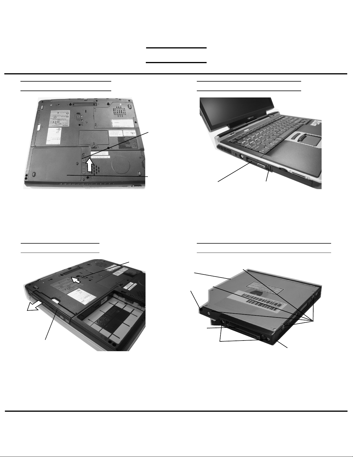
BATTERY PACK REMOVAL
Release
lever
Battery
Pack
1. Turn the computer upside down as shown.
2. Slide the battery release lever in the direction of the
arrow.
3. Lift out the battery.
Note: The battery release lever will only unlatch if the unit
is upside down.
SELECT BAY REMOVAL
OPTIONAL PC CARD REMOVAL
PC card
1. Press the eject button for the PC card you want to
remove.
2. Press the extended eject button to pop the PC Card
out.
3. Grasp the PC card and remove it.
NOTE: Before removing any PC Card device, make sure
it is “STOPPED” in the PC Card manager.
Eject button
CD-R/W/DVD-ROM DRIVE DISASSEMBLY
Release lever
Select bay
device
1. Turn the computer upside down.
2. Slide the release lever in the direction of the arrow.
3. Pull out the select bay device in the direction of the
arrow.
NOTE: If the lock screw is in locked position, remove it
and attach it to the other hole for temporary retention
of the screw.
CD-R/W/DVD-ROM
drive
Base cover
Connector
M2x8 silver
screws
1. Remove five M2x3 silver flat head screws securing
the base cover and lift out the cover.
2. Remove two M2x8 silver screws securing the
connector cover.
3. Remove the connector cover and the connector
from the CD-R/W/DVD-ROM drive.
M2x3 silver
flat head
screws
Connector cover
TOSHIBA
Tough Enough for Today’s World.
Page 4
FIELD REPLACEABLE UNIT DOCUMENTATION
TM
Tecra
S1 Series
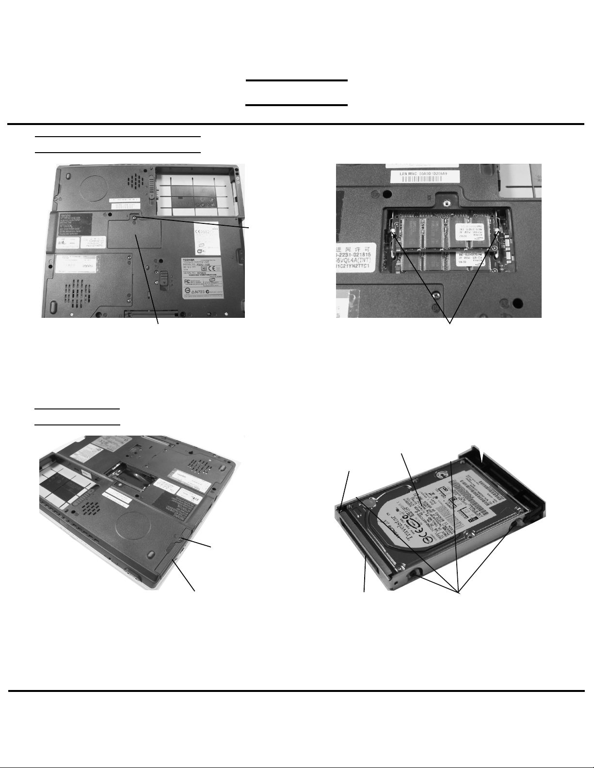
MEMORY MODULE REMOVAL
M2.5x2.8
silver flat
head screws
Memory cover
1. Turn the computer upside down.
2. Remove one M2.5x4 black screw securing the memory
cover and remove the memory cover.
HDD REMOVAL
M2.5x4 black flat
head screw
HDD assy
Memory clips
3. Spread the memory clips outward and pull the
memory module out of the connector on a
30 degree angle.
HDD
bracket
HDD connector
HDD
M3x4 flat head brass screws
1. Turn the computer upside down.
2. Remove one M2.5x4 black flat head screw securing
HDD assembly.
3. Slide the HDD assembly out of the HDD bay..
TOSHIBA
Tough Enough for Today’s World.
4. Remove four M3x4 brass flat head screws securing
the HDD to the bracket and lift the drive out of the
bracket.
5. Unplug the HDD connector from the drive.
Page 5

FIELD REPLACEABLE UNIT DOCUMENTATION
MODEM BOARD REMOVAL
TM
Tecra
S1 Series
Modem/CPU
cover
Modem
board
M2x4 black screws
1. Turn the computer upside down.
2. Remove two M2.5x4 black screws securing the
modem cover.
3. Remove the modem cover.
COOLING MODULE REMOVAL
Cooling
module
Fan cable
PJ770
silver flat head screws
1. Disconnect the fan cable from CN1007 on the system
board.
2. Remove four silver flat head screws securing
the cooling module.
3. Lift out the cooling module.
M2x4 brass screws
4. Remove two M2x4 silver flat head screws securing
the modem board.
5. Disconnect the modem board from PJ1006 on the
system board.
6. Disconnect the modem cable from JP1 on the
modem card.
CPU REMOVAL
CPU
Close
Open
Silicone grease
1. Insert a flat head screwdriver to the CPU lock
and rotate it counter-clockwise to unlock the CPU.
2. Lift out the CPU.
CPU lock
TOSHIBA
Tough Enough for Today’s World.
Page 6

FIELD REPLACEABLE UNIT DOCUMENTATION
TM
Tecra
S1 Series
KEYBOARD REMOVAL
M2.5x12 black screws
1. Turn the computer upside down.
2. Remove two M2.5x12 black screws securing the
keyboard holder.
KEYBOARD REMOVAL
M2.5x2.8 black screws
5. Remove two M2.5x2.8 black screws securing the
keyboard.
Keyboard holderKeyboard
3. Turn the computer right side up and open the
display panel.
4. Using the case separator, unlatch the keyboard
holder at the top of the keyboard.
Keyboard Keyboard cable
6. Lift out the keyboard and set it as shown above.
7. Disconnect the keyboard cable from CN7 on
the system board.
8. Lift out the keyboard.
CN7
TOSHIBA
Tough Enough for Today’s World.
Page 7

FIELD REPLACEABLE UNIT DOCUMENTATION
TM
Tecra
S1 Series
PALM REST COVER REMOVAL
Latch
Lacthes Palm rest cover
1. Turn the computer upside down.
2. Remove one M2x4 black flat head screw securing
the palm rest cover.
3. Release the two latches securing the palm rest cover.
TOUCH PAD REMOVAL
Touch pad plate
M2x3 silver flat head screws
M2x4 black flat head screw
Tape
4. Turn the computer right side up and open the display
panel.
5. Lift up the right side of the palm rest cover and slowly
pull towards the right to release the remaining
13 latches securing the palm rest.
Latches
Touch pad board
1. Remove two M2x3 sliver flat head screws securing the
touch pad plate
2. Peel off the tape securing the touch pad plate.
3. Slide the touch pad plate in the direction of the arrow
and lift out the touch pad plate.
TOSHIBA
Tough Enough for Today’s World.
4. Release the two latches securing the touch pad
board.
5. Lift out the touch pad board.
Page 8

FIELD REPLACEABLE UNIT DOCUMENTATION
TM
Tecra
S1 Series
WIRELESS LAN CARD REMOVAL
White coax
cable
Black coax
cable
Wireless
LAN card
Mini-PCI connector clips
1. Disconnect the black and white coax from the
wireless LAN card.
2. Spread the Mini-PCI connector clips and pull the
Wireless LAN card out of the connector about
45 degree angle.
SPEAKERS REMOVAL
RTC BATTERY REMOVAL
RTC cable
1. Remove the plastic insulator.
2. Disconnect the RTC cable from PJ5 on the
LED/Bluetooth board.
3. Lift out the RTC battery.
PJ5
RTC battery
M2.5x6 black screws
1. Turn the computer upside down.
2. Remove four M2.5x6 black screws securing the left
and right speakers.
TOSHIBA
Tough Enough for Today’s World.
M2.5x4 black flat head screw
3. Remove one M2.5x4 black flat head screw
securing the harness cover.
Harness cover
Page 9

FIELD REPLACEABLE UNIT DOCUMENTATION
TM
Tecra
S1 Series
SPEAKERS REMOVAL
Harness
cover
Left speaker cable
1. Lift up the harness cover and disconnect the left and
right speaker cables.
2. Lift out the left and right speakers.
LCD ASSEMBLY REMOVAL
Right speaker cable
LCD ASSEMBLY REMOVAL
M2.5X6 black screws
1. Turn the computer upside down.
2. Remove two M2.5x6 black screws securing the
LCD panel..
.
TOP COVER REMOVAL
Display
assy
M2.5x3.5
black flat
head screws
LCD/FL cable CN3 M2.5x6 black screws
1. Turn the computer right side up and open the display
panel.
2. Peel off the tapes securing the wireless cables.
3. Disconnect the LCD/FL cable from CN3 on the system
board.
4. Lift out the display assembly.
Tapes
1. Turn the computer upside down.
2. Remove five M2.5x3.5 black flat head screws
and seven M2.5x6 black screws securing the
bottom cover.
TOSHIBA
M2.5x3.5 black flat head screws
Tough Enough for Today’s World.
Page 10

FIELD REPLACEABLE UNIT DOCUMENTATION
TM
Tecra
S1 Series
TOP COVER REMOVAL
CN5005
M2.5x6 black
screws
CN13
Mic cable
3. Turn the computer right side up.
4. Remove three M2.5x6 black screws securing the top
cover.
3. Disconnect the Mic cable from CN13 and the speaker
extension cable from CN5005.
4. Gently lift out the top cover.
Speaker extension cable
SYSTEM BOARD REMOVAL
I/O BOARD REMOVAL
I/O board
cable
CN5003
1. Disconnect the I/O board cable from CN5003 on the
I/O board.
2. Remove one M2.5x4 black flat head screw
securing the I/O board..
I/O board
M2.5x4black flat head screws
I/O board
cable
CN5
CN8
Wireless LAN knob
1. Disconnect the touch pad harness from CN8 and
the I/O board cable from CN5 on the system board.
2. Gently lift up the right side of the system board and
lift it out.
3. Remove the wireless LAN knob from the system board.
System board
Touch pad harness
TOSHIBA
CN1005
Modem
harness
Cardbus connector
4. Disconnect the Modem harness from CN1005
on the system board.
5. Remove four M2x10 silver flat head screws
securing the Cardbus connector.
6. Disconnect the Cardbus connector from the
system board.
Tough Enough for Today’s World.
Page 11

FIELD REPLACEABLE UNIT DOCUMENTATION
TM
Tecra
S1 Series
14” LCD MASK REMOVAL
Latch
M2x6 silver
screws
Display mask
1. Remove two rubber seals at the top corners of the
display assembly and two mask seals at the bottom
corners of the display assembly.
2. Remove four M2.5x4 black flat head screws and four
M2x6 silver screws securing the display mask.
3. There are 18 latches securing the display mask.
Carefully insert your fingers between the display mask
and the LCD module and pry open the latches starting
from the bottom six latches, to the five latches on the
right and left sides, ending with the top six latches.
Mask seals
LCD
FL INVERTER AND 14” LCD REMOVAL
M2.5x4 black
flat head screws
LCD/
FL cable
FL inverter board
1. Remove one M2x3 silver flat head screw securing
FL inverter board.
2. Carefully lift up the FL inverter board and disconnect
the LCD/FL cable from CN1 and the FL cable
from CN2.
3. Remove two 2.5x4 black flat head screws securing
the LCD top cover.
M2x4 silver flat head screw
LCD
module
FL cable
4. Remove four M2x3 silver screws securing the LCD
module to the LCD brackets.
5. Gently lift out the LCD module and disconnect the
LCD/FL cable from the LCD module.
TOSHIBA
Tough Enough for Today’s World.
M2x3 silver
screws
 Loading...