

Page 1

Toshiba Personal Computer
TECRA S1
Maintenance Manual
TOSHIBA CORPORATION
S/ No.
TECRA S1 Maintenance Manual
Page 2

Copyright
© 2003 by Toshiba Corporation. All rights reserved. Under the copyright laws, this manual
cannot be reproduced in any form without the prior written permission of Toshiba. No patent
liability is assumed with respect to the use of the information contained herein.
Toshiba TECRA S1 Maintenance Manual
First edition Jan 2003
Disclaimer
The information presented in this manual has been reviewed and validated for accuracy. The
included set of instructions and descriptions are accurate for the TECRA S1 at the time of
this manual's production. However, succeeding computers and manuals are subject to
change without notice. Therefore, Toshiba assumes no liability for damages incurred
directly or indirectly from errors, omissions, or discrepancies between any succeeding
product and this manual.
Trademarks
Intel and Pentium are registered trademarks of Intel Corporation.
IBM, IBM PC/XT, PC/AT, PS/2 and OS/2 are registered trademarks of IBM Corporation.
MS-DOS and Windows are registered trademarks of Microsoft Corporation.
Sound Blaster and Pro are trademarks of Creative Technology Ltd.
UNIX is a registered trademark of X/Open Company Ltd.
NetWare are registered trademarks of Novell, Inc.
All other properties are trademarks or registered trademarks of their respective holders.
ii TECRA S1 Maintenance Manual
Page 3
Preface
This maintenance manual describes how to perform hardware service maintenance for the
Toshiba Personal Computer TECRA S1, referred to as TECRA S1 in this manual.
The procedures described in this manual are intended to help service technicians isolate
faulty Field Replaceable Units (FRUs) and replace them in the field.
SAFETY PRECAUTIONS
Four types of messages are used in this manual to bring important information to your
attention. Each of these messages will be italicized and identified as shown below.
DANGER: “Danger” indicates the existence of a hazard that could result in death or
serious bodily injury, if the safety instruction is not observed.
WARNING: “Warning” indicates the existence of a hazard that could result in bodily
injury, if the safety instruction is not observed.
CAUTION: “Caution” indicates the existence of a hazard that could result in property
damage, if the safety instruction is not observed.
NOTE: “Note” contains general information that relates to your safe maintenance
service.
Improper repair of the computer may result in safety hazards. Toshiba requires service
technicians and authorized dealers or service providers to ensure the following safety
precautions are adhered to strictly.
Be sure to fasten screws securely with the right screwdriver. If a screw is not fully
fastened, it could come loose, creating a danger of a short circuit, which could cause
overheating, smoke or fire.
If you replace the battery pack, RTC battery or backup battery, be sure to use only the
same model battery or an equivalent battery recommended by Toshiba. Installation of
the wrong battery can cause the battery to explode.
TECRA S1 Maintenance Manual iii
Page 4

The manual is divided into the following parts:
Chapter 1 Hardware Overview describes the TECRA S1 system unit and each
FRU.
Chapter 2 Troubleshooting Procedures explains how to diagnose and resolve
FRU problems.
Chapter 3 Test and Diagnostics describes how to perform test and diagnostic
operations for maintenance service.
Chapter 4 Replacement Procedures describes the removal and replacement of the
FRUs.
Appendices The appendices describe the following:
Handling the LCD module
Board layout
Pin assignments
Keyboard scan/character codes
Key layout
Wiring diagrams
BIOS Rewrite Procedures
iv TECRA S1 Maintenance Manual
Page 5

Conventions
This manual uses the following formats to describe, identify, and highlight terms and
operating procedures.
Acronyms
On the first appearance and whenever necessary for clarification acronyms are enclosed in
parentheses following their definition. For example:
Read Only Memory (ROM)
Keys
Keys are used in the text to describe many operations. The key top symbol as it appears on
the keyboard is printed in boldface type.
Key operation
Some operations require you to simultaneously use two or more keys. We identify such
operations by the key top symbols separated by a plus (+) sign. For example, Ctrl + Pause
(Break) means you must hold down Ctrl and at the same time press Pause (Break). If
three keys are used, hold down the first two and at the same time press the third.
User input
Text that you are instructed to type in is shown in the boldface type below:
DISKCOPY A: B:
The display
Text generated by the XXXXX that appears on its display is presented in the type face
below:
Format complete
System transferred
TECRA S1 Maintenance Manual v
Page 6

Table of Contents
Chapter 1 Hardware Overview
1.1 Features .................................................................................................................. 1-1
1.2 System Unit Components....................................................................................... 1-6
1.3 2.5-inch HDD ....................................................................................................... 1-12
1.4 DVD-ROM Drive................................................................................................. 1-13
1.5 CD-ROM Drive.................................................................................................... 1-14
1.6 CD-R/RW Drive................................................................................................... 1-15
1.7 CD-RW/DVD-ROM Drive .................................................................................. 1-16
1.8 Power Supply ....................................................................................................... 1-17
1.9 Batteries................................................................................................................ 1-19
Chapter 2 Troubleshooting
2.1 Outline.................................................................................................................... 2-1
2.2 Basic Flowchart...................................................................................................... 2-2
2.3 Power Supply ......................................................................................................... 2-6
2.4 System Board ....................................................................................................... 2-10
2.5 2.5-inch HDD ....................................................................................................... 2-20
2.6 Keyboard .............................................................................................................. 2-25
2.7 Display ................................................................................................................. 2-27
2.8 DVD-ROM Drive................................................................................................. 2-29
2.9 CD-ROM Drive.................................................................................................... 2-31
2.10 LAN...................................................................................................................... 2-33
2.11 Cooling Module.................................................................................................... 2-34
Chapter 3 Diagnostic Programs
3.1 General ................................................................................................................... 3-1
3.2 Quick Start.............................................................................................................. 3-3
3.3 Option..................................................................................................................... 3-9
vi TECRA S1 Maintenance Manual
Page 7

3.4 Subtests................................................................................................................. 3-18
3.5 System Test .......................................................................................................... 3-22
3.6 Memory Test ........................................................................................................ 3-29
3.7 Storage.................................................................................................................. 3-34
3.8 Video .................................................................................................................... 3-39
3.9 Communication (COMM).................................................................................... 3-47
3.10 Peripherl ............................................................................................................... 3-54
3.11 Audio.................................................................................................................... 3-58
3.12 Mode Error Codes and description....................................................................... 3-59
TECRA S1 Maintenance Manual vii
Page 8

Chapter 4 Replacement Procedures
4.1 General ................................................................................................................... 4-1
4.2 Cooling Module.................................................................................................... 4-18
4.3 CPU ...................................................................................................................... 4-21
4.4 HDD ..................................................................................................................... 4-24
4.5 Selectable Bay Module......................................................................................... 4-27
4.6 Touch Pad............................................................................................................. 4-31
4.7 RTC Battery ......................................................................................................... 4-35
4.8 Wireless Lan Card................................................................................................ 4-37
4.9 Keyboard .............................................................................................................. 4-39
4.10 Speaker ................................................................................................................. 4-42
4.11 Bluetooth Card..................................................................................................... 4-44
4.12 Top Cover with the Display Assembly ................................................................ 4-46
4.13 I/O Board.............................................................................................................. 4-50
4.14 System Board ....................................................................................................... 4-51
4.15 Display Mask........................................................................................................ 4-53
4.16 Inverter Board ...................................................................................................... 4-55
4.17 LCD Module ........................................................................................................ 4-57
viii TECRA S1 Maintenance Manual
Page 9

Appendices
Appendix A Handling the LCD Module ........................................................................... A-1
Appendix B Board Layout ................................................................................................ B-1
Appendix C Pin Assignments............................................................................................ C-1
Appendix D Keyboard Scan/Character Codes .................................................................. D-1
Appendix E Key Layout.....................................................................................................E-1
Appendix F Wiring Diagrams............................................................................................F-1
Appendix G BIOS Rewrite Procedures............................................................................. G-1
Appendix H EC/KBC Rewrite Procedures........................................................................ H-1
TECRA S1 Maintenance Manual ix
Page 10

x TECRA S1 Maintenance Manual
Page 11

Chapter 1
Hardware Overview
Page 12

1 Hardware Overview
1-ii TECRA S1 Maintenance Manual
Page 13

1 Hardware Overview
Chapter 1 Contents
1.1 Features ...................................................................................................................... 1-1
1.2 System Unit Components .......................................................................................... 1-6
1.3 2.5-inch HDD........................................................................................................... 1-12
1.4 DVD-ROM Drive .................................................................................................... 1-13
1.5 CD-ROM Drive ....................................................................................................... 1-14
1.6 CD-R/RW Drive ...................................................................................................... 1-15
1.7 CD-RW/DVD-ROM Drive...................................................................................... 1-16
1.8 Power Supply ........................................................................................................... 1-17
1.9 Batteries ................................................................................................................... 1-18
1.9.1 Main Battery....................................................................................... 1-18
1.9.2 Battery Charging Control ................................................................... 1-18
1.9.3 RTC Battery ....................................................................................... 1-19
TECRA S1 Maintenance Manual 1-iii
Page 14

1 Hardware Overview
Figures
Figure 1-1 Front of the computer.......................................................................................... 1-5
Figure 1-2 System unit configuration ................................................................................... 1-5
Figure 1-3 System unit block diagram.................................................................................. 1-6
Figure 1-4 2.5-inch HDD.................................................................................................... 1-12
Figure 1-5 DVD-ROM drive .............................................................................................. 1-13
Figure 1-6 CD-ROM drive ................................................................................................. 1-14
Tables
Table 1-1 2.5-inch HDD specifications .............................................................................. 1-12
Table 1-2 DVD-ROM drive specifications......................................................................... 1-13
Table 1-3 CD-ROM drive specifications............................................................................ 1-14
Table 1-4 CD-R/RW drive specifications........................................................................... 1-15
Table 1-5 CD-RW/DVD-ROM drive specifications .......................................................... 1-16
Table 1-6 Battery specifications ........................................................................................ 1-18
Table 1-7 Quick/normal charging time.............................................................................. 1-18
Table 1-8 RTC battery charging/data preservation time .................................................... 1-19
1-iv TECRA S1 Maintenance Manual
Page 15

1.1 Features
1
1 Hardware Overview
1.1 Features
The Toshiba TECRA S1 is a lightweight notebook PC based on the Mobile Banias processor,
providing high-speed processing capabilities and advanced features. The computer employs
a Lithium Ion battery that allows it to be battery-operated for a longer period of time. The
display uses a 14.1-inch XGA or 15-inch XGA/UXGA (BTOable) LCD panel, capable of
displaying up to 16M colors at a resolution of 1024 by 768 pixels (XGA), 1200 by 1600
pixels (UXGA).
The (PGA socket supports BTO/CTO for the CPU so that the system can be designed to suit
your needs.
The computer has the following features.
Processor
The CPU is the Mobile Banias (Pentium M).
Mobile Banias (Pentium M) operating at 1.484 V
1.3, 1.4, 1.5, 1.6 GHz
On-die level 2 cache 1MB
Host bridge system controller
System controller: Intel 855 PM (ODEM) + ICH4-M
Memory
The computer has a pair of SO DIMM slots and comes standard with one 256MB
module. It supports PC2100 and uses SO DIMMs (DDR SDRAM) driven at 2.5 V,
accepting BTO/CTO for your memory requirements. It can incorporate up to 1 GB of
main memory using the following sizes of memory modules:
128 MB (8M×16×8P)
•
256 MB (16M×16×8P)
•
512 MB (16M×16×16P)
•
512 MB (32M×16×8P)
•
TECRA S1 Maintenance Manual 1-1
Page 16

1 Hardware Overview
Hard disk drive (HDD)
The computer accommodates one 2.5-inch HDD with any of the following storage
capacities:
30 GB (9.5 mm thick) ATA100
•
40 GB (9.5 mm thick) ATA100
•
60 GB (9.5 mm thick) ATA100
•
Floppy disk drive (FDD)
An external 3.5-inch FDD can be connected to a USB port.
A 3.5-inch three-mode drive is available that supports 720KB, 1.2MB, and 1.44MB
formats.
Selectable bay
The Selectable Bay can accommodate a DVD-ROM drive, CD-ROM drive, CD-RW
drive, or Multi-Drive.
1.1 Features
This bay can also be used to install a secondary HDD or secondary battery available
as an option.
Expansion dock
The computer can accommodate Advanced Port Replicator and CardDock, which
support the function of Cold, Hot, Warm Dock/Undock. Expansion dock is covered
with a lid when Docking I/F is not used.
Display
The LCD displays available come in the following three sizes:
14.1” XGA-TFT color display, resolution 1024×768, 16M colors
•
15” XGA-TFT color display, resolution 1024×768, 16M colors
•
15” UXGA-TFT color display, resolution 1600×1200, 16M colors
•
The computer can use an external monitor along with the LCD display at the same
time.
Keyboard
The keyboard has 85 keys conforming to the US key layout.
The keyboard has 85 keys confirming to the UK key layout.
Batteries
The computer has a removable Lithium Ion battery pack and an internal RTC battery.
1-2 TECRA S1 Maintenance Manual
Page 17

1.1 Features
Universal Serial Bus (USB) ports
The computer has three USB ports to daisy-chain a maximum of 127 USB devices.
The serial data transfer rate is 480 Mbps (high speed), 12 Mbps (full speed) or 1.5
Mbps (low speed). These ports support PnP installation and hot plugging.
Parallel port
A Centronics compatible parallel port is provided to connect a printer or another
parallel device. The port is IEEE-1284 compliant and supports Extended Capabilities
Port (ECP).
Serial port (RS-232C port)
A 9-pin serial interface port is provided to connect a serial device such as a serial
printer, mouse, or modem.
External monitor port
A 15-pin external monitor port is provided, through which the computer
automatically recognizes an external VESA DDC 2B compatible monitor.
1 Hardware Overview
PS/2 mouse/keyboard port
A 6-pin PS/2 mouse/keyboard port is provided to connect an IBM( PS/2 compatible
keyboard or mouse. It accepts a Y splitter cable.
PC Card slot
A PC Card slot is provided to hold either two PC Card Standard Type II (5.0 mm)
cards or one Type III (10.5 mm) card, capable of using a variety of PC Cards
including 16-bit Multiple Function PC Cards and CardBus cards. It also supports
booting from a PC Card HDD.
Toshiba Dual Pointing Device
Toshiba Dual Pointing Device has 2 kinds of input devices. One is AccuPoint,
another one is TouchPad.
Fast Serial InfraRed (FIR) communications port
An IrDA 1.1 compatible FIR port is provided, enabling wireless communication at a
high speed of 1.15 or 4 Mbps.
TECRA S1 Maintenance Manual 1-3
Page 18

1 Hardware Overview
Sound system
The AD1886 integrated audio controller supports multimedia. The sound system
contains the following:
MIDI replay feature
•
Stereo speakers
•
Headphone jack
•
External microphone jack
•
LAN
The internal LAN board supports 10BASE-T and 100BASE-TX, enabling connection
to a LAN at up to 100 Mbps. It also supports Wake-up On LAN. The LAN board
has the RJ45 jack to directly accommodate a LAN cable.
Wireless LAN
The internal Mini PCI Card slot has a 2.4-GHz DSSS wireless LAN card installed.
The LAN card is IEEE 802.11b compliant, delivering a peak transfer rate of 11 Mbps.
The antenna is integrated in the system unit. The LAN card supports 128-bit WEP.
1.1 Features
Another LAN card is IEEE 802.11 a/b combo.
Internal modem
The computer contains a MDC, enabling data and fax communication. It supports
ITU-TV.90. The transfer rates are 56 Kbps for data reception, 33.6 Kbps for data
transmission, and 14,400 bps for fax transmission. Note, however, that the actual
speed depends on the line quality. The RJ11 modem jack is used to accommodate a
telephone line.
Bluetooth
The bluetooth is option integrated device. It uses RF transmission in 2.4 GHz band.
1-4 TECRA S1 Maintenance Manual
Page 19
1.1 Features
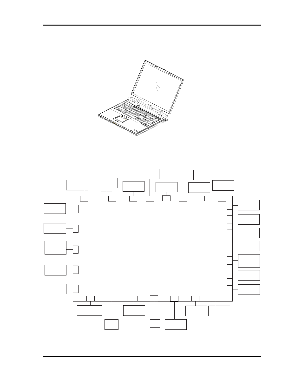
Figures 1-1 and 1-2 show the front of the computer and its system unit configuration,
respectively.
1 Hardware Overview
Figure 1-1 Front of the computer
Cooling
Module
AC Adapter
Docking
I/F
Conn
Serial
Parallel
CPU
PS/2 Mouse
/Keyboard
Expansion
Memory
CRT
SD
Card
PC Card
Slot
System Board
Selectable
Bay
Speaker
Left
Speaker
Right
LAN
Head
Phone
Ext.
MIC
Ext.
Speaker
LCD/FL
Inverter
Int MIC
Bluetooth
I/F
Conn.
Keyboard
RTC
Battery
Main
Battery
Int
HDD
IR
Wireless
Lan
Figure 1-2 System unit configuration
TECRA S1 Maintenance Manual 1-5
Page 20
1 Hardware Overview 1.2 System Unit Block Diagram
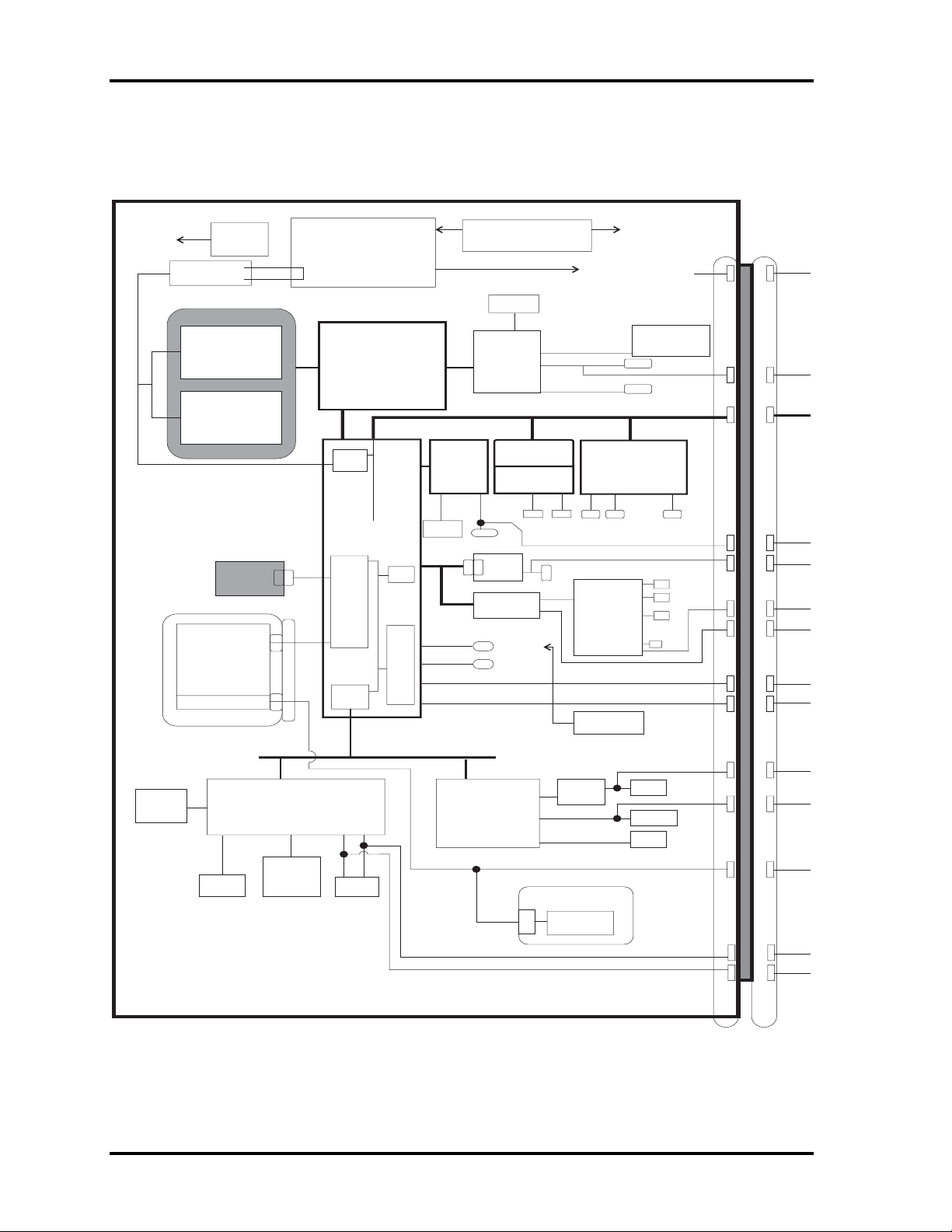
1.2 System Unit Components
Figure 1-3 is a block diagram of the system unit.
P
ADM1032
(Thermal Sensor)
PC 2100DRAM
133MHz
Expansion
Memory
128/256/512
Expansion
Memory
128/256/512
2nd HDD
CD-ROM
DVD-ROM
CD-R/RW
Multi Driver
(LS 120)
(ZIP 250)
2nd BATTERY
MAX6501
Int-HDD
30-80GB
9.5mm
CPU :Intel
Mobile
Banias
1.4, 1.5,1.6, 1.7GM2
Micro FC.PGA2
MCH-M
North Bridge
855PM(ODEM)
HUB
Link
SM
Bus
Cont.
South Bridge
(ICH4-M)
IDE
Cont.
PCI-PC
Bridge
AC97
USB
Cont.
(02)
Internal LPC
LAN
Cont.
82562
EEPROM
AC
USB P0-P2
USB P3
USB P4
USB P5
AGP
Main CLKGeneral.
(ICS950810)
CPUVID
32MB
ATI
M9P
Mini
PCI Slot
802.11b or
Combo
(Wireless LAN)
RJ45
MDC
Modem
CODEC
AD1886
USB Port
BT
Antena
LM2729
LVDS
NTSC/PAL
Internal PCIBus
Cardbus Controller
PCMCIA
RJ11
AMP
(LM4873)
USB
FDD
CB720
LCD 14",15"
CRT
Speakerx2
Mic
HP
DC
SD
Line out
Line in
USB
USB
Flash
ROM
K/B
(1/2) EC/KBC
(LPC 47N253)
Touch
Pad
PS/2
(2/2) SuperI/O
(LPC47N253)
I2C
DR/RCV
(MAX3243)
Main Battery
E2PROM
Serial
Parallel
FIR
I2C
PS/2
PS/2
Figure 1-3 System unit block diagram
1-6 TECRA S1 Maintenance Manual
Page 21

1.2 System Unit Block Diagram 1 Hardware Overview
The system unit of the computer consists of the following components:
Processor: Mobile Banias
Mobile Banias
•
Core speed: 1.3, 1.4, 1.5, 1.6 GHz
−
System bus: 400 MHz
−
Core operating at 1.484 V
−
Integrated level 1 cache: 64 KB
−
(32KB instruction cache and 32KB data cache)
On-die level 2 cache 1 MB
−
MMX and Katmai New Instruction (KNI) supported
−
Memory
Two BTO/CTO-capable expansion memory slots are provided, coming standard with
one 256MB module. They can hold 128/256/512MB expansion memory modules
available as options to grow up to 1 GB.
PC2100 DDR SDRAM supported
•
128/256/512MB modules supported
•
128 MB (8M x 16 x 8P)
−
256 MB (16M x 16 x 8P)
−
512 MB (16M x 16 x 16P)
−
512 MB (32M x 16 x 8P)
−
2.5 volt operation
•
No parity bit
•
64-bit data transfer
•
TECRA S1 Maintenance Manual 1-7
Page 22

1 Hardware Overview 1.2 System Unit Block Diagram
BIOS ROM (flash E2PROM)
4Mb x 1 chip (512KB flash parts)
•
64 KB used for system BIOS
−
64 KB used for VGA
−
20 KB used for PnP
−
4 KB for password security
−
36 KB used for bootstrap
−
84 KB used for ACPI P code
−
36 KB used for LOGO
−
48 KB used for LAN
−
64 KB used for EC BIOS
−
92 KB reserved
−
3.3 volt operation
−
Access time of 90 ns
−
8-bit data transfer
−
System controllers
North Bridge: Intel 855 PM (ODEM) (MCH-M)
•
South Bridge: Intel ICH4-M
•
PC Card controller
CPU interface and control
−
DRAM control
−
PCI master/slave interface (PCI R2.2 compliant)
−
AGP master/slave interface (AGP1.0 compliant, AGP V2.0 compliant
−
x 4 modes)
Enhanced DMA controller
−
Interrupt controller
−
Counter/timer
−
PCI IDE controller
−
Support for ATA-66 (GB) and ATA-100 (30/40/60 GB)
−
USB interface
−
SMBus interface
−
Super I/O interface
−
Power management control
−
Suspend/resume control
−
ACPI support
−
CB720
•
CardBus/PC Card controller
−
SD Card controller
−
1-8 TECRA S1 Maintenance Manual
Page 23

1.2 System Unit Block Diagram 1 Hardware Overview
Video controller
ATI M9P
•
LCD control
−
External RGB output control
−
NTSC/PAL output control
−
Video RAM
32 MB (DDR SDRAM)
•
Sound controller
The ICH4-M integrated audio controller supports multimedia. The sound system
contains the following:
MIDI replay feature
•
Stereo speakers
•
Headphone jack
•
Internal microphone jack
•
External microphone jack
•
ICH4-M integrated audio controller + AD1886
•
3D sound (surround) feature
−
16-bit, 48-KHz stereo record/replay feature
−
Full-duplex (simultaneous record/replay capability)
−
KBC/EC (Keyboard Controller/Embedded Controller)
A single LPC 47N253 chip is used to serve as KBC/ EC.and Super IO.
KBC
•
Scan controller function
−
Interface controller function
−
Controlling the switching between the AccuPoint and external PS/2
−
mouse or between the built-in keyboard and external PS/2 keyboard or
their simultaneous operation
TECRA S1 Maintenance Manual 1-9
Page 24

1 Hardware Overview 1.2 System Unit Block Diagram
EC
•
Power supply sequence control
−
Thermal control
−
LED control
−
Beep control
−
Device ON/OFF
−
Cooling fan speed control
−
Universal I/O port
−
Dock power supply control
−
Battery capacity check
−
Flash memory reprogramming function
−
EC access interface
−
I2C communication control
−
RS-232C driver
MAX3243
•
Conversion of signal levels for communication with an external device
−
Battery E2 PROM
24C02 equivalent (128 words x 16 bits, I2C interface) integrated in the battery
•
pack
Clock Generator
ICS950810A
•
Modem Controller
Built-in MDC card with XircomLucent Mars3+SiDAA
•
Functions of the modem controller:
•
Storing records of battery use
−
Generating the clock signal required for the system
−
Digital signal conductor protection
−
Ring wake-up support
−
Communication codes supported:
−
For data communication:
V.90 (56K bps) data communication control
V.32 bis (14.4K, 12K, 9600)
V.22 bis (2400, 1200)
V.22 (1200)
V.23 (1200, 600, 75)
V.21 (300)
1-10 TECRA S1 Maintenance Manual
Page 25

1.2 System Unit Block Diagram 1 Hardware Overview
For fax:
V.17 (14.4K, 12K, 9600, 7200)
V.29 (9600, 7200, 4800)
V.27 ter (4800, 2400)
V.21 ch2 (300)
-AC97 interface
LAN controller
Intel 82562
•
Wake-up On LAN support
−
Remote boot support
−
100BASE-TX support
−
Wireless LAN controller
2.4 GHz DSSS wireless LAN card plugged in the internal Mini PCI Card slot
•
Super I/O
LPC 47N253
•
−
−
−
Serial port control
Parallel port control
Infrared communications control
TECRA S1 Maintenance Manual 1-11
Page 26
1 Hardware Overview 1.3 2.5-inch HDD
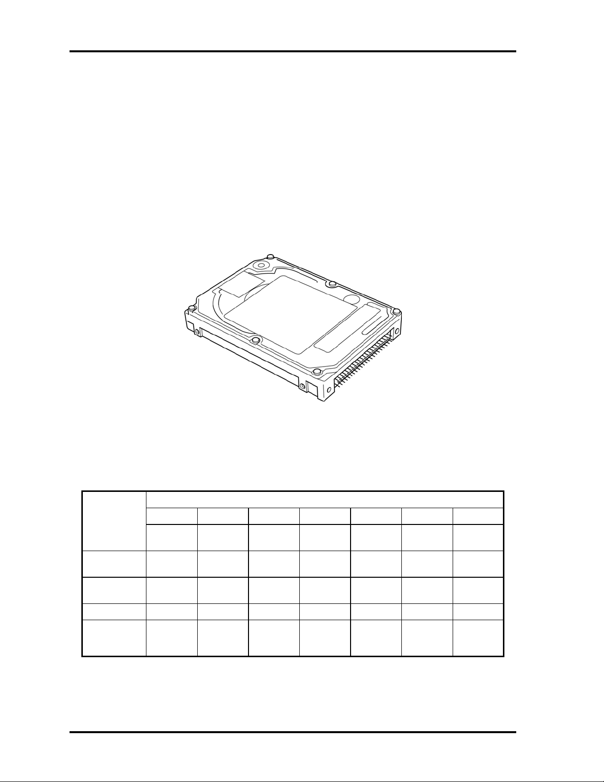
1.3 2.5-inch HDD
The computer contains an extremely low-profile and lightweight, high-performance HDD.
The HDD incorporates a 2.5-inch magnetic disk and mini-Winchester type magnetic heads.
Storage capacities supported are 30, 40, and 60 GB.
The HDD interface is Enhanced IDE, ATA66 (for GB), or ATA100 (for 30/40/60 GB).
The HDD is shown in Figure 1-4 and its specifications are listed in Table 1-1.
Figure 1-4 2.5-inch HDD
Table 1-1 2.5-inch HDD specifications
Specifications
Item
Formatted
capacity (GB)
User data
sectors
Bytes/sector 512 512 512 512
Rotational
speed
(RPM)
Toshiba HGS Toshiba Toshiba
MK6022
GAX
60.0116GB 40.0007GB 40.0007GB 30.0058GB
117,210,240 78,140,160 78,140,160 58,605,120
5400rpm 5400rpm 5400rpm 4200rpm
IC25N040
ATCS05
MK4019
GAX
MK3021
GAS
1-12 TECRA S1 Maintenance Manual
Page 27
1.4 DVD-ROM Drive 1 Hardware Overview
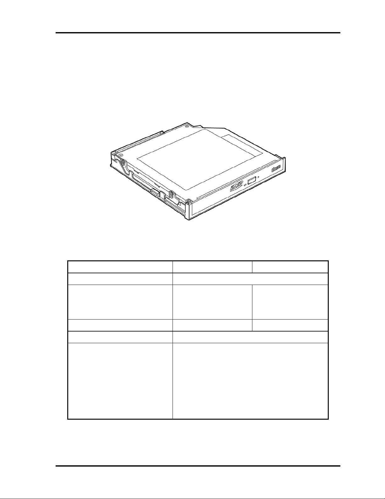
1.4 DVD-ROM Drive
The DVD-ROM drive accepts 12-cm (4.72-inch) and 8-cm (3.15-inch) discs. The drive
provides high-speed data transfer, playing back a DVD at up to 8x speed and reading up to
10,820 Kbytes per second from DVD-ROM and 3,600 Kbytes per second from CD-ROM.
The DVD-ROM drive is shown in Figure 1-5 and its specifications are listed in Table 1-2.
Figure 1-5 DVD-ROM drive
Table 1-2 DVD-ROM drive specifications
Item DVD-ROM mode CD-ROM mode
Data transfer rate (Mbytes/s) 33.3 (U-DMA transfer mode 2)
Access time (ms)
Average random access (ms)
Average full stroke access (ms)
Rotational speed (RPM) 4,670 Max 5,100Max
Data buffer size (Kbytes) 256
Formats supported DVD-ROM, DVD-R (Read)
110 (Typ.)
200 (Typ.)
CD-DA, CD+(E)G, CD-MIDI, CD-TEXT
CD-ROM, CD-ROM XA, CD-I
CD-I Bridge (Photo-CD, Video-CD)
Multisession CD (Photo-CD, CD-EXTRA, CD-R,
CD-RW)
85 (Typ.)
180 (Typ.)
CD-R (Read), CD-RW (Read)
TECRA S1 Maintenance Manual 1-13
Page 28
1 Hardware Overview 1.5 DVD-ROM Drive
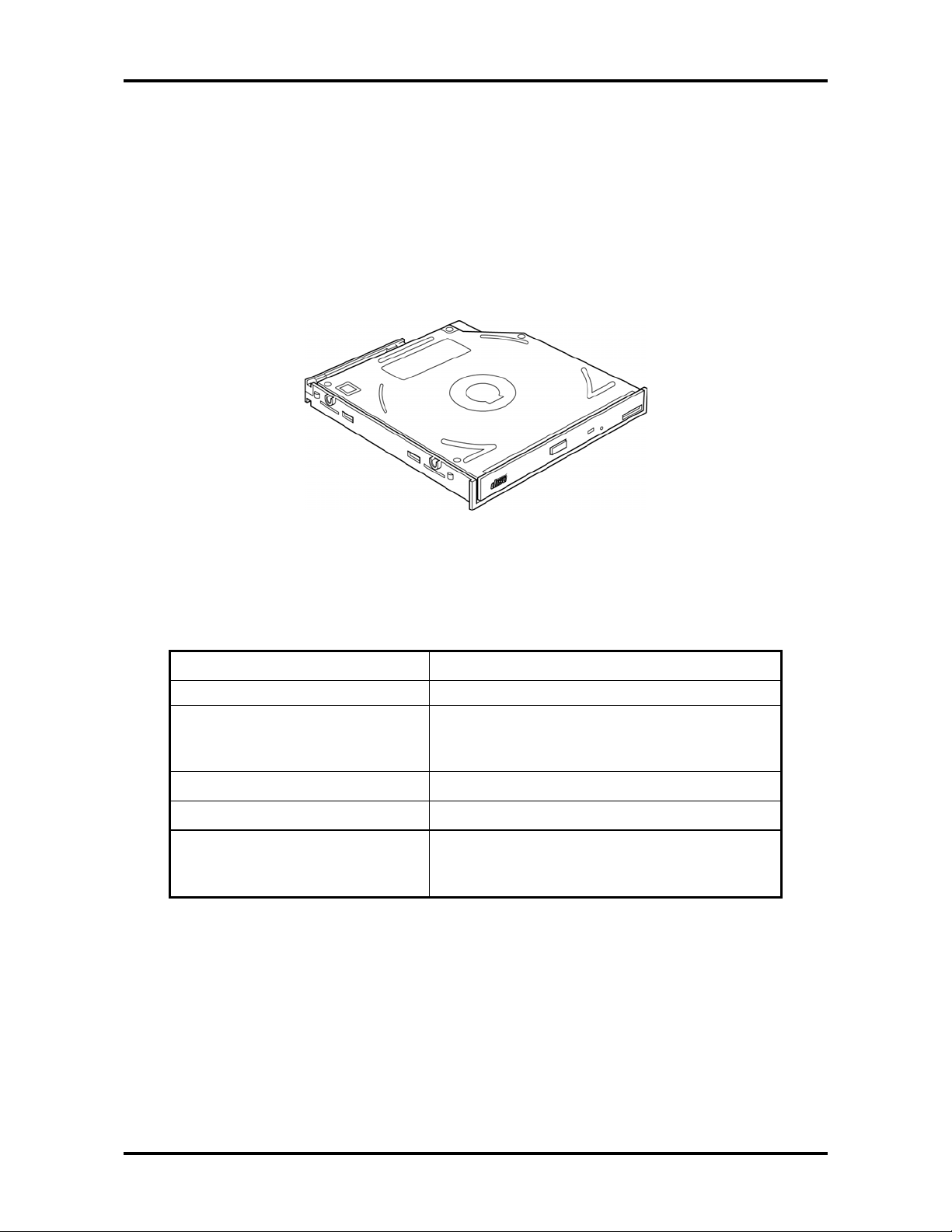
1.5 CD-ROM Drive
The CD-ROM drive accepts 12-cm (4.72-inch) and 8-cm (3.15-inch) discs. The drive
provides high-speed data transfer at up to 24x.
The CD-ROM drive is shown in Figure 1-6 and its specifications are listed in Table 1-3.
Figure 1-6 CD-ROM drive
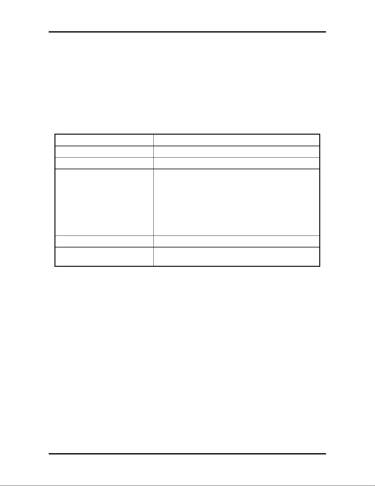
Table 1-3 CD-ROM drive specifications
Item
Data transfer rate (Mbytes/s)
Access time (ms)
Average random access
Average full stroke access
Rotational speed (RPM) 5,136
Data buffer size (Kbytes) 128
Formats supported CD-DA, CD-ROM, CD-R, CD-ROM XA, CD-I
FMV, Photo CD (Multisession) , VIDEO CD,
CD Extra (CD Plus), CD-G, CD-RW
24× mode (Max.)
33.3 (U-DMA transfer mode 2)
110 (Typ.)
240 (Typ.)
1-14 TECRA S1 Maintenance Manual
Page 29
1.6 CD-R/RW Drive 1 Hardware Overview
1.6 CD-R/RW Drive
The CD-R/RW drive accepts 12-cm (4.72-inch) and 8-cm (3.15-inch) discs.
The specifications of the CD-R/RW drive are listed in Table 1-4.
Table 1-4 CD-R/RW drive specifications
Item Specifications
Data transfer rate (Mbytes/s) 16.6 (U-DMA transfer mode 2)
Access time (ms) 110 (max 24, Typ.)
Speed Read:
CD-ROM, CD-R (max 24)
CD-RW (max 24)
Write:
CD-R (max 8)
CD-RW (max 8)
Cache (Mbytes) 2
Formats supported Video CD, Photo CD, CD-ROM, CD-ROM XA,
CD-EXTRA, CD-R, CD-Rewritable, CD-DA, CD-Text
TECRA S1 Maintenance Manual 1-15
Page 30
1 Hardware Overview 1.7 CD-RW/DVD-ROM Drive
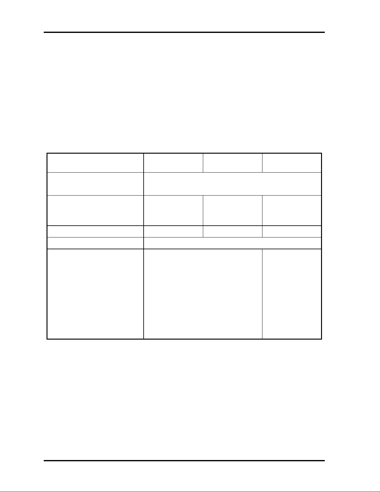
1.7 CD-RW/DVD-ROM Drive
The CD-RW/DVD-ROM drive accepts 12-cm (4.72-inch) and 8-cm (3.15-inch) discs. At
maximum, the drive can play back a DVD at 8x speed, read CD-ROM at 24x speed, and
write CD-R/RW at 8x speed.
The specifications of the CD-RW/DVD-ROM drive are listed in Table 1-5.
Table 1-5 CD-RW/DVD-ROM drive specifications
Item DVD-ROM mode CD-ROM mode CD-R/CD-RW
(Write mode)
Data transfer rate (Mbytes/s) 33.3 (U-DMA transfer mode 2)
16.7 (PIO mode 4, Multiword DMA mode 2)
Access time (ms)
Average random access
Average full stroke access
Rotational speed (RPM) 4,594 Max 5,136 Max 2,297 Max
Data buffer size (Mbytes) 2
Formats supported DVD:
110
250
DVD-ROM (DVD-5, DVD-9, DVD-10,
DVD-18), DVD-R (read)
CD:
CD-DA, CD+(E)G, CD-MIDI, CD-TEXT,
CD-ROM, CD-ROM XA, MIXED MODE
CD, CD-I, CD-I Bridge (Photo-CD,
Video-CD), Multisession CD (Photo-CD,
CD-EXTRA, Portfolio, CD-R, CD-RW),
CD-R, CD-RW
90
200
-
-
CD-DA, CD+(E)G,
CD-MIDI, CDTEXT, CD-ROM,
CD-ROM XA,
MIXED MODE CD,
CD-I, CD-I Bridge
(Photo-CD, VideoCD), Multisession
CD (Photo-CD,
CD-EXTRA,
Portfolio)
1-16 TECRA S1 Maintenance Manual
Page 31

1.8 Power Supply 1 Hardware Overview
1.8 Power Supply
The power supply unit provides many different voltages for the system board and performs
the following functions:
1. Power input monitor
Checks whether the DC power supply (AC adapter) is connected to the computer.
•
Checks whether the battery pack is connected to the computer.
•
Monitors the DC power supply input voltage (AC Adapter output voltage).
•
2. Power supply's internal control
Turns on and off the battery pack charging power supply.
•
Issues a charging current instruction to the PWM control IC of the battery pack
•
charging power supply.
Controls the supply of DC power supply input (AC Adapter output) to the power
•
supply unit.
Controls the supply of power to the system block (load/logic circuit side).
•
Controls forced shutdown if the power supply malfunctions.
•
3. Logic circuit control
Instructs the gate array to enable/disable tuning the power on.
•
Controls power-on/off operation.
•
4. Status display
Turns on the DC IN LED (in orange or green).
•
Battery indicator (in orange or green)
•
5. External interface
Performs communication through the I2C bus (via the internal EC/KBC).
•
Transfers the power supply operation mode.
•
6. Output monitor
Monitors the voltage output to the system block (load/logic circuit side).
•
Monitors the voltage, overvoltage, input/output current of the battery pack.
•
Monitors the internal temperature of the battery pack.
•
Monitors the supply voltage from the AC adapter.
•
TECRA S1 Maintenance Manual 1-17
Page 32

1 Hardware Overview 1.9 Batteries
1.9 Batteries
The computer has the following three types of batteries:
Main battery pack
Real time clock (RTC) battery
Secondary battery pack (Optionally installed in the selectable bay)
Table 1-6 lists the specifications of these batteries.
Table 1-6 Battery specifications
Battery name Material Output voltage Capacity
Main battery pack Lithium Ion 10.8 V 6,450 mAh
RTC battery Lithium Ion 3.0 V 15 mAh
Secondary battery pack Lithium Ion 10.8V 4,300 mAh
1.9.1 Main Battery
The main battery pack serves as the computer's main power source when the AC adapter is
not attached. The main battery maintains the state of the computer so that it can resume it.
1.9.2 Battery Charging Control
Battery charging is controlled by LPC 47N253. When the AC adapter and battery pack are
attached to the computer, the LPC 47N253 controls the charge on/off state and detects a full
charge.
Battery Charge
When the AC adapter is attached, the battery is charged by off-state charge when the
system is powered off or by on-state charge when it is powered on.
Table 1-7 Quick/normal charging time
Charge time
Off-state charge About 3 hours
On-state charge About 4 - 9 hours
1-18 TECRA S1 Maintenance Manual
Page 33

1.9 Batteries 1 Hardware Overview
NOTE:
The time required for normal charge depends on the power consumption by the
system. Using the fluorescent lamp and frequently accessing the disk consume much
power and lengthen the charge time.
Any of the following cases stops battery charge:
1. The battery becomes fully charged.
2. The AC adapter or battery pack is removed.
3. The battery or AC adapter voltage is abnormal.
Detection of full charge
A full charge is detected only when the battery is being charged by quick or normal
charge. A full charge is detected when either of the following conditions is met:
1. The current in the battery charging circuit drops below the predetermined
value.
2. The charging time exceeds the fixed limit.
1.9.3 RTC Battery
The RTC battery provides power to keep the current date, time and other system information
in memory while the computer is turned off. Table 1-8 lists the charging time and data
preservation period of the RTC battery.
Table 1-8 RTC battery charging/data preservation time
Status Time
Charging
time
AC Adapter or main battery pack used
(power on)
50 hours
TECRA S1 Maintenance Manual 1-19
Page 34

2 Troubleshooting
2
Chapter 2
Troubleshooting
2-i TECRA S1 Maintenance Manual
Page 35

2 Troubleshooting
Chapter 2 Contents
2.1 Outline........................................................................................................................ 2-1
2.2 Basic Flowchart ......................................................................................................... 2-2
2.3 Power Supply............................................................................................................. 2-6
Procedure 1 Power Icon Check........................................................................... 2-6
Procedure 2 Connection Check........................................................................... 2-8
Procedure 3 Replacement Check ........................................................................ 2-9
2.4 System Board........................................................................................................... 2-10
Procedure 1 Message Check ........................................................................... 2-11
Procedure 2 Printer Port LED Check (in Boot Mode) .................................... 2-12
Procedure 3 Printer Port LED Check (in Resume Mode)............................... 2-17
Procedure 4 Test Program Check ................................................................... 2-18
Procedure 5 Replacement Check ..................................................................... 2-18
2.5 2.5-inch HDD........................................................................................................... 2-19
Procedure 1 Message Check ............................................................................. 2-19
Procedure 2 Partition Check .......................................................................... 2-19
Procedure 3 Format Check.............................................................................. 2-20
Procedure 4 Test Program Check ................................................................... 2-21
Procedure 5 Connector Check and Replacement Check................................. 2-22
2.6 Keyboard.................................................................................................................. 2-23
Procedure 1 External Keyboard Check........................................................... 2-23
Procedure 2 Test Program Check ................................................................... 2-23
Procedure 3 Connector Check and Replacement Check................................. 2-23
2.7 Display ..................................................................................................................... 2-25
Procedure 1 External Monitor Check ............................................................. 2-25
Procedure 2 Test Program Check ................................................................... 2-25
Procedure 3 Connector Check and Replacement Check................................. 2-25
2.8 DVD-ROM Drive .................................................................................................... 2-27
Procedure 1 DVD-ROM Cleaning Check....................................................... 2-27
Procedure 2 Test Program Check ................................................................... 2-27
Procedure 3 Connector Check and Replacement Check................................. 2-27
2-ii TECRA S1 Maintenance Manual
Page 36

2 Troubleshooting
2.9 CD-ROM Drive ....................................................................................................... 2-29
Procedure 1 CD-ROM Cleaning Check.......................................................... 2-29
Procedure 2 Test Program Check ................................................................... 2-29
Procedure 3 Connector Check and Replacement Check................................. 2-29
2.10 LAN ......................................................................................................................... 2-31
Procedure 1 Test Program Check ................................................................... 2-31
Procedure 2 Connector Check and Replacement Check................................. 2-31
2.11 Cooling Module ....................................................................................................... 2-32
Procedure 1 Test Program Check ................................................................... 2-32
Procedure 2 Connector Check and Replacement Check................................. 2-32
TECRA S1 Maintenance Manual 2-iii
Page 37

2 Troubleshooting
Figures
Figure 2-1 Basic flowchart .............................................................................................. 2-3
Figure 2-2 Printer port LED ......................................................................................... 2-12
Figure 2-3 Printer port LED board ............................................................................... 2-12
Tables
Table 2-1 Printer port LED boot mode status (1/3)...................................................... 2-14
Table 2-2 Printer port LED resume mode status (1/7) ................................................. 2-17
Table 2-3 HDD error code and status........................................................................... 2-21
2-iv TECRA S1 Maintenance Manual
Page 38

2.1 Outline 2 Troubleshooting
2.1 Outline
This chapter describes the fault diagnosis procedures for field replaceable units (FRUs) in the
computer.
The FRUs covered here are as follows:
1. System board 2. 2.5-inch HDD 3. Keyboard
4. Display 5. DVD-ROM drive 6. CD-ROM
7. Cooling module 8. Lan
See Chapter 4 for the procedures to replace FRUs and Chapter 3 for the procedures to use test
programs
The following tools are required to perform the diagnostic procedures:
1. Diagnostics (maintenance test program) disk
2. Phillips screwdrivers (2 mm, 2.5 mm)
3. Cleaning disk kit (for CD-ROM/ DVD-ROM drive cleaning)
4. Bootable CD
5. Printer port LED (i.e LPT Port LED)
6. Printer port (parallel port) loopback connector (i.e. LPT Port)
7. Serial port loopback connector (i.e. COM Port)
8. PC Card loopback connector
9. Multimeter
10. External monitor
11. External PS/2 keyboard
12. External PS/2 mouse
13. Multimedia sound system with line-in and line-out ports
14. Headphone
15. Microphone
16. External FDD attachment
17. A-BEX TEST CD-ROM TCDR-702
18. Music CD
19. DVD-ROM TSD-1 (TOSHIBA EMI DVD Test Media)
TECRA S1 Maintenance Manual 2-1
Page 39

2 Troubleshooting 2.2 Basic Flowchat
2.2 Basic Flowchart
The basic flowchart in Figure 2-1 serves as a guide for identifying a possibly faulty FRU.
Before going through the diagnostic flowchart steps, verify the following:
Ask the user if a password has been registered and, if so, ask him or her to enter the
password. If the user has forgotten the system password, attach a printer loopback
connector to the printer port, then turn the power on. When booted, the computer
overrides password protection and automatically erases the current password.
Make sure the Toshiba version of Windows® 98SE, 2000, or XP has been installed
on the HDD. Any other operating system can cause the computer to malfunction.
Make sure any piece of optional equipment has been installed.
2-2 TECRA S1 Maintenance Manual
Page 40

2.2 Basic Flowchat 2 Troubleshooting
r
play
No
No
No
No
No
No
Start
Connect the AC Adapte
DC IN LED on ??
Yes
BATTERY LED on ??
Yes
Turn the power on.
Any error message displayed ??
Message "In Touch with
Tomorrow Toshiba" dis
ed
Follow the power supply diagnostic
Procedure in Section 2.3
Follow the power supply diagnostic
Procedure in Section 2.3
Yes
Follow the system board diagnostic
Procedure in Section 2.4
Follow the display diagnostic
Procedure in Section 2.8
Yes
Yes
"Password=" displayed ??
See the previous page to
delete the password.
OS started ??
Foll ow the HDD diagnostic
Procedure in Section 2.6
Yes
Figure 2-1 Basic flowchart (1/2)
TECRA S1 Maintenance Manual 2-3
Page 41

2 Troubleshooting 2.2 Basic Flowchat
N
g
g
g
g
NoNoN
Keyboard works well ??
Insert Bootable CD into CD-ROM
Diagnostic Program
Loaded ??
Yes
Perform each test with the
diagnostic program.
Any error detected by the
dia
nostic program ??
Yes
o
Follow the keyboard diagnostic
Procedure in Section 2.7
Follow the CD-ROM diagnostic
Procedure in Section 2.10
Identify the test resulting in the error
and perform the appropriate
dia
nostic procedures
Perform the continuous test to check if the
error is intermittent.
Yes
Identify the test resulting in the
Any error detected by the
error and perform the appropriate
dia
nostic program ??
dia
nostic procedures
o
The system is normal.
END
Figure 2-1 Basic flowchart (2/2)
2-4 TECRA S1 Maintenance Manual
Page 42

2.2 Basic Flowchat 2 Troubleshooting
If the diagnostic program cannot detect an error, the error may be intermittent. Run the
continuous test program repeatedly to isolate the problem. Check the log utilities function to
confirm which diagnostic test detected the error, then perform the appropriate
troubleshooting procedures as follows:
1. If an error is detected by the System test, Memory test, Async test, Printer test,
Sound test, or Real Timer test, follow the system board troubleshooting procedures in
Section 2.4.
2. If an error is detected by the Hard Disk test, follow the HDD troubleshooting
procedures in Section 2.6.
3. If an error is detected by the Keyboard test, follow the keyboard troubleshooting
procedures in Section 2.6.
4. If an error is detected by the Display test, follow the display troubleshooting
procedures in Section 2.8.
5. If an error is detected by the DVD-ROM test, follow the DVD-ROM troubleshooting
procedures in Section 2.9.
6. If an error is detected by the CD-ROM test, follow the CD-ROM troubleshooting
procedures in Section 2.10.
7. If an error is detected by the LAN test, follow the LAN troubleshooting procedures in
section 2.12.
8. If an error is detected by the Fan On/Off test, follow the cooling module
troubleshooting procedures in Section 2.13.
TECRA S1 Maintenance Manual 2-5
Page 43

2 Troubleshooting 2.3 Power Supply
2.3 Power Supply
The power supply in the computer controls many functions and components. To check if the
power supply is defective or malfunctioning, follow the troubleshooting procedures below as
instructed.
Procedure 1 Power Icon Check
Procedure 2 Connection Check
Procedure 3 Replacement Check
Procedure 1 Power Icon Check
The following two power LEDs indicate the power supply status:
Battery LED
DC IN LED
The power supply controller displays the power supply status through the Battery and DC IN
LEDs as in the tables below.
Battery LED
Battery LED Power supply status
On in orange Battery being charged
On in green Battery fully charged, with AC adapter connected
Blinking in orange
(at equal intervals)
Off Else
Battery low *1 while driving the computer
2-6 TECRA S1 Maintenance Manual
Page 44

2.3 Power Supply 2 Troubleshooting
DC IN LED
DC IN LED Power supply status
On in green DC power being supplied (from the AC adapter)
Off Else
If the DC IN LED off, follow the steps below:
1. Remove the battery pack and the AC adapter to shut off power supply to the
computer.
2. Attach the battery and AC adapter back again.
If the LED still off, follow the steps below:
Check 1 Make sure the DC IN LED goes on in green. If it does not, go to Procedure 2.
Check 2 Make sure the Battery LED goes on in orange or green. If it does not, go to
Procedure 3.
TECRA S1 Maintenance Manual 2-7
Page 45

2 Troubleshooting 2.3 Power Supply
Procedure 2 Connection Check
Power is supplied to the system board as illustrated below:
AC
System board
adaptor
AC power cord
AC adaptor cord
Battery pack
Follow the steps below to check whether each connector has been connected correctly:
Check 1 Make sure the AC adaptor and AC power cord have been firmly plugged into
the DC IN 15V socket and wall outlet, respectively. When they have been
connected correctly, perform Check 2.
Check 2 Connect a new AC adaptor and AC power cord.
• If the DC IN LED does not go on, go to Procedure 3.
• If the battery LED does not go on, perform Check 3.
Check 3 Make sure the battery pack has been correctly installed in the computer. If the
battery LED does not go on while the battery pack has been installed correctly,
go to Procedure 3.
2-8 TECRA S1 Maintenance Manual
Page 46

2.3 Power Supply 2 Troubleshooting
Procedure 3 Replacement Check
The system board, power supply board, or CPU may be faulty. Disassemble the computer
according to Chapter 4 and follow the steps below:
Check 1 Replace the power supply board with a new one. If the battery pack is still not
working properly, perform Check 2.
Check 2 Replace the system board with a new one. If the battery pack is still not
working properly, perform Check 3.
Check 3 Replace the CPU with a new one.
TECRA S1 Maintenance Manual 2-9
Page 47

2 Troubleshooting 2.4 System Board
2.4 System Board
To check if the system board is defective or malfunctioning, follow the troubleshooting
procedures below as instructed.
Procedure 1 Message Check
Procedure 2 Printer Port LED Check (in Boot Mode)
Procedure 3 Printer Port LED Check (in Resume Mode)
Procedure 4 Test Program Check
Procedure 5 Replacement Check
2-10 TECRA S1 Maintenance Manual
Page 48

2.4 System Board 2 Troubleshooting
Procedure 1 Message Check
When the power is turned on, the system performs the self-diagnostic Power On Self Test
(POST) embedded in the BIOS ROM. The POST tests and initializes each IC on the system
board.
If an error message appears on the display, perform Check 1.
If there is no error message, go to Procedure 2.
If there is no error beep code tone out, go to Procedure 3
If Toshiba MS-DOS or Toshiba Windows 95/98/NT/2000 is loaded normally, go to
Procedure 5.
Check 1 If the following error message is displayed on the screen, press the F1 key as
prompted. These errors occur when the system configuration preserved in the
RTC memory (generally called CMOS memory) does not match the actual
configuration or when the data is lost.
If you press the F1 key as prompted by the message, the TSETUP screen
appears to set the system configuration. If the error message appears
frequently when the power is turned on, replace the RTC battery. If any other
error message is displayed, perform Check 2.
*** Bad RTC battery ***
Check system. Then press [F1] key
Check 2 If the following error message is displayed on the screen,
press any key as prompted by the message.
The error message appears when either data stored in RAM to be resumed is
lost because the battery has been exhausted or the system board is faulty.
If any other error message displays, perform Check 3
RESUME FAILURE and PRESS ANY KEY TO CONTINUE.
Check 3 The POST checks the system board. When the POST detects an error, the
system stops
or a error beep code tone out
or an error POST message appears.
TECRA S1 Maintenance Manual 2-11
Page 49

2 Troubleshooting 2.4 System Board
Procedure 2 Printer Port LED Check (in Boot Mode)
The printer port LED displays the POST status and error status by turning lights on and off as
an eight-digit binary value obtained in the boot mode after the system unit is switched on.
Figure 2-2 shows the printer port LED.
Figure 2-2 Printer port LED
Figure 2-3 illustrates how the printer port LED shows a status value.
Printer port LED status = 35H
Figure 2-3 Printer port LED board
2-12 TECRA S1 Maintenance Manual
Page 50

2.4 System Board 2 Troubleshooting
Follow the steps below to use the printer port LED:
1. Turn on the computer and set the boot mode.
2. Turn off the computer.
3. Plug the printer port LED into the computer's parallel port (printer port).
4. Read the LED status from left to right as you are facing the back of the computer.
5. Convert the LED status from binary to hexadecimal notation.
6. If the final LED status is FFh (normal status), go to Procedure 5.
7. If the final LED status matches any other status in Table 2-1, go to Procedure 6.
NOTE: The printer port LED displays each status upon completion of the corresponding
POST test item. If the POST terminates with 21h displayed on the printer port LED, for
example, the POST has completed KBC initialization and detected an error
TECRA S1 Maintenance Manual 2-13
Page 51

2 Troubleshooting 2.4 System Board
Table 2-1 Printer port LED boot mode status (1/3)
LED Status
(Hexadecimal)
0H DIAG_SYSTEM_INIT Boot started,read the cmos data for makesure
1H DI A G_A 20_DI SA BL E Di sabl e A20 t hrough A 20
2H DIAG_INIT_CHIPSET Initialize ChipsetSet,load chipset default
3H DIAG_TEST_RAM send patten for test the basic 640k RAM
4H DI A G_M OVE_ BB_LOADER Move boot l oad segment i nto t he RAM
5H DI A G_EX ECUTE_I N_DRAM program executi on f rom D RAM
6H DIAG_USER_FLASH_CHECK Test print port for check
7H DIAG_SHADOW_BIOS Decompress the system BIOS, and
8H DIAG_CHECKSUM_BIOS Checksum System BIOS ROM
9H DIAG_NORMAL_BOOT Jump to the reset point
AH DI A G_CRI SIS_BOOT Proceed wi th Cri si s B oot,f irst i nit ial
FH DIAG_FATAL_ERROR Fatal Error,li ke the RAM error or ROM error
CCH D I A G _C RI SI S_ B EGI N St ar t pr oc ess th e Cr i si s r eco v ery pr o cedu r e
99H DI A G_RESUM E_RAM_ ERROR Resume SMRA M not Found
Test Item
main board power i s stable
si z e c hach e R A M
cri sis opti on i s enabl e or not
Shadow System BIOS to RAM
superi o and boot devi ce
Description
1 0H D EB U G_ M I SC_ RE SET D i sabl e i n t ern al cac he r am, and
reset cpu
11H DEB UG_CS_FA ST_A 20_RESET Turn off FA STA 20 f or post, and check hav e key b oar d
controllor
12H DEBUG_POST_SIGNAL_POR Initial PIC enable INT and Signal Power On Reset
13H DEBUG_CS_CHIP_INIT Initial ize the Chi pset and hook PCI BIOS
14H DEBUG_OEM_ISA_VGA_SEARCH Search For ISA Bus VGA Adapter, from address c000
to e000
15H DEB UG_HWI O_SETUP_CTC1 I nit ial ize Counter and Ti mer chi p
16H DEB UG_OEM_SET_CMOS_REGS User register conf ig through CM OS
17H DEB UG_CS_MEMORY_ SI ZE Si ze M emor y, and detect memory ti ming,
setup memory contr oll or
18H DEBUG_POST_TEST_RAM Initialize and test the f irst 64k memory
19H DEBUG_ GEN_TEST_ROM S checksum t he sy stem ROM
1AH DEBUG_HWIO_RESET_INTS Reset PI C's status
1BH DEBUG_V IDEO_V ID EO_I NI T I ni ti al i ze V i deo Adapter(s),and check vga rom and
vga ram
1CH DEBU G_VI DEO_EQUI P_I NI T I nit ial ize V ideo (6845 Regs),set displ ay mode
1DH DEBU G_VI DEO_COLOR_I NI T I nit ial ize Col or A dapter,and setup di spl ay reg.
1EH DEBUG_VIDEO_BW_INIT Initialize Monochrome Adapter,and setup display
reg.
1FH DEBU G_HWI O_TEST_DM A_ PA G Send out some value,t o test 8237A Page Regi st er s
2-14 TECRA S1 Maintenance Manual
Page 52

2.4 System Board 2 Troubleshooting
S
G
Table 2-2 Printer port LED boot mode status (2/3)
LED Status
(Hexadecimal)
20H DEBUG_KEYB_SELFTEST_CTLR Send sel ftest command (AAH) to test Keyboard
21H DEB UG_K EY B_RESET_K EYBOARD Test Keyboard Contr oll er and i nit ialize keyboard
22H DEBUG_POST_CHECK_CMOS_RAM Send test petten to Check CMOS Ram
23H DEBUG_POST_TEST_BATT_CMOS_
24H DEBUG_HWIO_TEST_DMA_CTLRS Use DMA to copy data for Test the DMA controllers
25H DEB UG_HWI O_I NI T_8237 I niti ali ze 8237A Contr oll er
26H DEBUG_POST_INIT_VECS Install and Iniitialize interrupt Vectors
27H DEB UG_RAM_QUI CK_SI ZE Enter memory pr otect mode,use change RAM bank to
28H DEB UG_RAM_PROT_ENTRY _1 Memory prot ected mode entered safely
29H DEBUG_RAM_SIZE_DONE Test the basic 640k r am, RA M test compl eted
2AH D EBU G_RAM _PROT_EX IT Protected mode exi t successful
2BH DEBUG_CS_SHADOW_SETUP Shadow system and video BIOS to RAM if CMOS
2CH DEBUG_V IDEO_EQUI P_I NIT_ INI T Goi ng To Ini ti ali ze 6845 CRT controllor
2DH DEBUG_V IDEO_B W_SEARCH Search For Monochrome A dapter
2EH D EBU G_VI DEO_COLOR_ SEA RCH Search For Col or A dapter
2FH DEBUG_V IDEO_SI GNON Signon messages di spl ayed
Test Item
contr oll or if o. k. return (55h)
contr oll or
Test Battery Fai l & check CMOS X-SUM
do RA M Quick Sizi ng
requests shadowSet up Shadow
Description
30H DEB UG_OEM_CONFI G_K BD_ CTL For speci al ini ti ali ze of keyboard control l or
31H DEBUG_KEYB_PRESENT_TEST Test the keyboard controllor ,If Keyboard
Pr esent
32H DEB UG_K EY B_TEST_ IRQ1 Cl ear keyboard buf fer and sen k ey boar d command
to test Keyboard Interrupt
33H DEBUG_KEYB_TEST_CMD Send keyboard command to turn off keyboard LED
and Test some Keyboard Command Byte
34H DEB UG_RAM_FULL _TEST TEST memory pr ocedure, for test, blank and
count al l RAM
35H DEBUG_RAM_PROT_ENTRY_2 Eneter the memory protected mode for test al l expand
memory
36H DEB UG_RAM_TEST_DONE Test and bl ank all memory compl ete
37H DEBUG_RAM_PROT_EXIT_2 Switch the memory from Protected mode to real mode
38H DEBUG_KEYB_OUTPUT_PORT Disable A20 status for memory test finish
39H DEB UG_CS_CACHE_SETUP Set up Cache Contr oll er
3AH DEBUG_HWIO_TEST_PERIODIC Check and test the timer 0 interrupt funct ion is Worki ng
3BH DEBUG_GEN_CHECK_RTC test for RTC ticking
3CH DEBUG_GEN_INIT_HARD_VECS Install and initialize the hardware vectors
3DH DEBUG_MOUSE_INIT Clear keyboard buff er for search and I nit the Mouse
3EH D EBU G_KEY B_SET_ LEDS_1 Send keyboard command to Update keyboard NUM LOCK status
3FH DEBUG_OEM_DEVICE_CONFI
special init of COMM and LPT ports
TECRA S1 Maintenance Manual 2-15
Page 53

2 Troubleshooting 2.4 System Board
Table 2-2 Printer port LED boot mode status (3/3)
LED Status
(Hexadecimal)
40H DEBUG_CS_CONFIG_PORTS Configure the COMM and LPT ports
41H DEBUG_FLOP_INIT According cmos data to initial ize the floppies
42H DEBUG_WINI_INIT Scan and initialize the hard disk, and display the result
43H DEBUG_HWIO_ROM_INIT Search option rom from c800 to e000 and to Initialize
44H DEBUG_OEM_INIT_POWER_MAN Check special device initial power management functi on
4 5H D EB UG_ K E Y B_ SET _ L ED S_2 C l ear key bo ar d bu f f er and U pd ate N U ML O CK status
46H DEBUG_HWI O_FI ND_80X 87 Test For Coprocessor I nstall ed,and enable
47H DEBUG_OEM_LAST_MINUTE_INIT Run OEM functions before boot, and enable
48H DEBUG_MISC_LAUNCH_INT19 Post code will finish,ready to run int19
49H DEBUG_BEGIN_BOOT_CODE Into Int19, to boot from floppy or other
50H DEBUG_ACPI_INIT Initialize the ACPI f unction
51H DEBUG_PM_CPU_INIT Power manager initial & GEYSERVILLE CPU
52H DEBUG_USB_HC_INIT Clear USB status register and Initiallize
Test Item
on crt
opti on ROMs
coprocessor interrupt
L1,L 2 cache
and l oad OS
boot devi ce
initialize
the USB Hub controllor
Description
2-16 TECRA S1 Maintenance Manual
Page 54

2.4 System Board 2 Troubleshooting
Procedure 3 Printer Port LED Check (in Resume Mode)
The printer port LED displays the POST status and error status by turning lights on and off as
an eight-digit binary value obtained in the resume or suspend mode after the system unit is
switched on.
Follow the steps below to use the printer port LED:
1. Turn on the computer and set the resume or suspend mode.
2. Turn off the computer.
3. Plug the printer port LED into the computer's parallel port (printer port).
4. Read the LED status from left to right as you are facing the back of the computer.
5. Convert the LED status from binary to hexadecimal notation.
6. If the final LED status is FFh (normal status), go to Procedure 5.
7. If the final LED status matches any other status in Table 2-2, go to Procedure 6.
Table 2-2 Printer port LED resume mode status (1/7)
< Resume mode >
LED Status
(Hexadecimal)
0H DIAG_SYSTEM_INIT Boot started,read the cmos data for makesure
1H DI AG_A 20_DI SABLE Di sabl e A20 through A20
2H DI AG_I NI T_CHI PSET Ini ti al ize Chi psetSet,l oad chi pset default
3H DIAG_TEST_RAM send patten for test the basi c 640k RAM
4H DI AG_M OVE_BB_LOADER Move boot l oad segment i nto the RA M
5H DI AG_EX ECUTE_IN_DRA M program executi on f rom DRA M
6H DIAG_USER_FLASH_CHECK Test print port for check
7H DIAG_SHADOW_BIOS Decompress the system BIOS, and
8H DIAG_CHECKSUM_BIOS Checksum System BIOS ROM
9H DIAG_NORMAL_BOOT Jump to the reset point
AH DIAG_CRISIS_BOOT Proceed with Crisis Boot,first initial
FH DIAG_FATAL_ERROR Fatal Error,like the RAM error or ROM error
CCH DIAG_CRISIS_BEGIN Start process the Crisi s recovery procedure
99H DI AG_RESUME_RA M_ERROR Resume SMRA M not Found
Test Item
main board power is stable
size chache RAM
crisi s opti on i s enabl e or not
Shadow System BIOS to RAM
superio and boot devi ce
Description
TECRA S1 Maintenance Manual 2-17
Page 55

2 Troubleshooting 2.4 System Board
Procedure 4 Test Program Check
The maintenance test program contains several programs for diagnosing the system board
and CPU. Execute the following test programs using the procedures described in Chapter 3.
1. System test
2. Memory test
3. Keyboard test
4. Display test
5. Printer test (i.e LPT Port test)
6. COM Port test
7. Hard Disk test
8. Mouse test
9. IrDA test
10. SD Card test
11. CD-ROM/DVD-ROM test
12. Sound test
13. LAN test
If an error is detected during these tests, go to Procedure 6
Procedure 5 Replacement Check
The system board, memory, or CPU may be defective. Disassemble the computer following
the steps described in Chapter 4 and replace the system board, memory module or CPU with
a new one.
2-18 TECRA S1 Maintenance Manual
Page 56

2.6 2.5-inch HDD 2 Troubleshooting
2.5 2.5-inch HDD
To check if the 2.5-inch HDD is defective or malfunctioning, follow the troubleshooting
procedures below as instructed.
Procedure 1 Message Check
Procedure 2 Partition Check
Procedure 3 Format Check
Procedure 4 Test Program Check
Procedure 5 Connector Check and Replacement Check
CAUTION: The contents of the 2.5-inch HDD will be erased when the HDD 2.5-inch
HDD diagnostic test or formatting is executed. Save the required contents of the HDD to
floppy disks or other storage drive in advance.
Procedure 1 Message Check
When the computer's HDD does not function properly, some of the following error messages
may appear on the display. Follow the steps below to check the HDD.
Check 1 If either of the following messages appears, go to Procedure 2. If the following
messages do not appear, perform Check 3.
Insert system disk in drive
Press any key when ready .....
or
Non-System disk or disk error
Replace and press any key
Check 2 Check TSETUP to see if the Hard Disk option has been set to “Not used”. If
so, choose another setting and restart the computer. If the problem persists, go
to Procedure 2.
Procedure 2 Partition Check
Enter the Toshiba MS-DOS system. Perform the following checks:
Check 1 Type C: and press the Enter key. If you cannot change to drive C, perform
Check 2. If you can change to drive C, perform Check 3.
Check 2 Type FDISK and press the Enter key. Choose “Display partition information”
from the FDISK menu. If drive C is listed, perform Check 3. If drive C is not
listed, return to the FDISK menu and choose the option to create a DOS
TECRA S1 Maintenance Manual 2-19
Page 57

2 Troubleshooting 2.6 2.5-inch HDD
partition on drive C. Then restart the computer.. If the problem persists, go to
Procedure 3.
Check 3 If drive C is listed as active in the FDISK menu, perform Check 4. If drive C is
not listed as active, return to the FDISK menu and choose the option to set the
active partition for drive C. Then restart the computer. If the problem persists,
perform Check 4.
Check 4 Enter DIR C: and press the Enter key. If the following message is displayed,
go to Procedure 3. If contents of drive C are listed on the display, perform
Check 5.
Invalid media type reading drive C
Abort, Retry, Fail?
Check 5 Use the SYS command in the Toshiba MS-DOS system to install system files.
If the following message appears on the display, the system files have been
transferred to the HDD. Restart the computer. If the problem persists, go to
Procedure 3.
System transferred
NOTE: If the computer is running Windows 95 OSR 2 or higher or Windows 98/2000 and
the hard disk capacity is more than 512 MB, the FDISK program will ask if you need
support for a partition larger than 2 GB. Select Y for large partition support; however, be
sure to read the precaution regarding access by other operating systems.
Procedure 3 Format Check
The 2.5-inch HDD is formatted using the low-level format program and the MS-DOS
FORMAT program. Using these programs, follow the steps below to format the HDD.
Check 1 Enter FORMAT C:/S/U to format the HDD and transfer system files. If the
following message appears on the display, the HDD has been formatted.
Format complete
If an error message appears on the display, refer to the Toshiba MS-DOS
Manual for more information and perform Check 2.
Check 2 Run the test program to format the 2.5-inch HDD with a low-level format
option. See Chapter 3 for details on how to use the test program.
If the following message appears on the display, the HDD low-level format is
complete. Partition and format the HDD using the MS-DOS FORMAT
command.
Format complete
2-20 TECRA S1 Maintenance Manual
Page 58

2.6 2.5-inch HDD 2 Troubleshooting
p
r
y
p
pp
If you cannot format the HDD using the test program, go to Procedure 4.
Procedure 4 Test Program Check
Run the HDD test program stored on the maintenance test program disk for all test items.
See Chapter 3 for details on how to use the test program.
If an error is detected during the HDD test, an error code and status will be displayed. The
error codes and their status names are listed in Table 2-3. If an error code is not generated
and the problem still exists, go to Procedure 5.
Table 2-3 HDD error code and status
Code Status
1 Get Parameter Fail !
2 Read Old Data Error
3 Write Pattern Error
4 Read Back Data Error
5 Data Com
are Erro
6 Restore Data Error
7 Read Verif
Error
9 Seek Error
10 Disk Controller Self Test Failed
11 Disk Controller Test unex
ected interrupt Failed
12 Disk Controller action Test Failed
13 disk dos not su
ort SMART
14 disk read attribute threshold error
15 disk read attribute value error
16 disk SMART attribute value error
TECRA S1 Maintenance Manual 2-21
Page 59

2 Troubleshooting 2.6 2.5-inch HDD
Procedure 5 Connector Check and Replacement Check
The HDD or system board may be faulty. Disassemble the computer following the steps
described in Chapter 4 and perform the following checks:
Check 1 Make sure the following connectors have been firmly connected to the HDD,
system board and CPU.
HDD
System board
CPU
If any connector is loose or off, reconnect it firmly and return to Procedure 1.
If there is still an error, perform Check 2.
Check 2 The HDD may be damaged. Replace it with a new one following the
disassembling instructions in Chapter 4. If the problem persists, perform
Check 3.
Check 3 The System board may be damaged. Replace it with a new one following the
disassembling instructions in Chapter 4. If the problem persists, perform
Check 4.
Check 4 The CPU may be damaged. Replace it with a new one following the
disassembling instructions in Chapter 4.
2-22 TECRA S1 Maintenance Manual
Page 60

2.7 Keyboard 2 Troubleshooting
2.6 Keyboard
To check if the computer’s keyboard is defective or malfunctioning, follow the
troubleshooting procedures below as instructed.
Procedure 1 External Keyboard Check
Procedure 2 Test Program Check
Procedure 3 Connector Check and Replacement Check
Procedure 1 External Keyboard Check
Connect a PS/2 or compatible keyboard to the computer's PS/2 keyboard/mouse port, then
boot the computer. The computer automatically detects the external keyboard even if resume
mode is enabled.
If the external keyboard works correctly, the internal keyboard may be faulty. Go to
Procedure 3.
If the external keyboard appears to have the same problem as the internal keyboard, the
system board may be faulty. Go to Procedure 2.
Procedure 2 Test Program Check
Execute the Keyboard test available as part of the maintenance test program. See Chapter 3
for information on how to perform the test.
If an error is detected in the test, go to Procedure 3. If no error is detected, the keyboard
itself is normal.
Procedure 3 Connector Check and Replacement Check
The keyboard or system board may be disconnected or faulty. Disassemble the computer
following the steps described in Chapter 4 and perform the following checks:
Check 1 Make sure the keyboard cable has been firmly connected to the system board.
Keyboard
System board
CPU
If the cable is loose or off, reconnect it firmly and return to Procedure 2. If
there is still an error, perform Check 2.
Check 2 The keyboard may be faulty. Replace it with a new one following the
instructions in Chapter 4. If the problem persists, perform Check 3.
TECRA S1 Maintenance Manual 2-23
Page 61

2 Troubleshooting 2.7 Keyboard
Check 3 The System board may be faulty. Replace it with a new one following the
instructions in Chapter 4. If the keyboard is still not functioning properly,
perform Check 4.
Check 4 The memory may be defective. Replace the memory module with a new one
following the steps described in Chapter 4. If the problem persist, perform
Check 5.
Check 5 The CPU may be faulty. Disassemble the computer following the steps
described in Chapter 4 and replace the CPU with a new one.
2-24 TECRA S1 Maintenance Manual
Page 62

2.8 Display 2 Troubleshooting
2.7 Display
To check if the computer’s display is defective or malfunctioning, follow the troubleshooting
procedures below as instructed.
Procedure 1 External Monitor Check
Procedure 2 Test Program Check
Procedure 3 Connector Check and Replacement Check
Procedure 1 External Monitor Check
Connect an external monitor to the computer's external monitor port, then boot the computer.
The computer automatically detects the external monitor even if resume mode is enabled.
If the external monitor works correctly, the internal LCD, LCD/FL cable, or FL may be
faulty. Go to Procedure 3.
If the external monitor appears to have the same problem as the internal monitor, the system
board may be faulty. Go to Procedure 2.
Procedure 2 Test Program Check
Insert the diagnostics bootable CD in the computer's CD ROM, turn on the computer and run
the test. See Chapter 3 for information on how to perform the test.
If an error is detected in the test, go to Procedure 3. If no error is detected, the display itself
is normal.
Procedure 3 Connector Check and Replacement Check
The display unit has an LCD module, Fluorescent lamp (FL), panel close switch and FL
inverter board. Any of the components or their connections may be defective. Disassemble
the computer following the steps described in Chapter 4, then perform the following checks:
(1) If the FL does not light, perform Check 1.
(2) If characters or graphics are not displayed normally, perform Check 5.
(3) If the FL remains lit when the display is closed, the panel close switch may be
defective. Perform Check 8.
Check 1 Make sure the following cables have been firmly connected to the system
board and FL inverter board.
FL
FL inverter board
System board
CPU
HV cable LCD/FL cable
If any of the cables is loose or off, reconnect it firmly and return to Procedure
3. If there is still an error, perform Check 2.
Check 2 The LCD/FL cable may be faulty. Replace it with a new one and return to
Procedure 3. If there is still an error, perform Check 3.
TECRA S1 Maintenance Manual 2-25
Page 63

2 Troubleshooting 2.8 Display
Check 3 The FL may be faulty. Replace it with a new one and return to Procedure 3. If
there is still an error, perform Check 4.
Check 4 The FL inverter board may be faulty. Replace it with a new one and return to
Procedure 3. If there is still an error, perform Check 5.
Check 5 Make sure the LCD/FL cable has been firmly connected to the system board
and LCD module.
FL inverter board
System board
LCD/FL cable
CPU
If the cable is loose or off, reconnect it firmly and return to Procedure 3. If
there is still an error, perform Check 6.
Check 6 The LCD/FL inverter cable may be faulty. Replace it with a new one and
return to Procedure 3. If there is still an error, perform Check 7.
Check 7 The LCD module may be faulty. Replace it with a new one and return to
Procedure 3. If there is still an error, perform Check 8.
Check 8 The System board may be faulty. Replace it with a new one. If there is still an
error, perform Check 9.
Check 9 The CPU may be faulty. Replace it with a new one following the instructions
in Chapter 4.
Check 10 The memory may be defective. Replace the memory module with a new one
following the steps described in Chapter 4. If the problem persist, perform
Check 10.
2-26 TECRA S1 Maintenance Manual
Page 64

2.9 DVD-ROM Drive 2 Troubleshooting
2.8 DVD-ROM Drive
To check if the internal DVD-ROM drive is defective or malfunctioning, follow the
troubleshooting procedures below as instructed.
Procedure 1 DVD-ROM Cleaning Check
Procedure 2 Test Program Check
Procedure 3 Connector Check and Replacement Check
Procedure 1 DVD-ROM Cleaning Check
1. Turn off the power to the computer.
2. Open the DVD tray by inserting a slender object such as a straightened paper clip into
the eject hole. The object must be long enough to activate the eject mechanism.
3. Clean the laser pickup lens with a lens cleaner. Apply the cleaner to a cloth and wipe
the lens.
4. If the DVD-ROM drive still does not function properly after cleaning, go to
Procedure 2.
Procedure 2 Test Program Check
Execute the CD-ROM/DVD-ROM drive test program available as part of the maintenance
test program. Insert the diagnostics CD in the computer's CD-ROM, turn on the computer
and run the test. Then insert a test DVD (Toshiba-EMI DVD-ROM TEST DISK TSD-1) into
the DVD-ROM drive. See Chapter 3 for information on how to perform the test.
If any error is detected by the test, go to Procedure 3.
Procedure 3 Connector Check and Replacement Check
The DVD-ROM drive is connected to the system board by the connector. The connector
may be disconnected from the system board or faulty. Disassemble the computer following
the steps described in Chapter 4 and perform the following checks:
Check 1 Make sure the following connector has been firmly connected to the DVD-
ROM drive and the system board.
DVD-ROM
drive
Attachment case
Connector
System board
CPU
If the connector is loose or off, reconnect it firmly and return to Procedure 2.
If there is still an error, perform Check 2.
Check 2 The connector may be faulty. Replace the connector with a new one following
the steps in Chapter 4. If the DVD-ROM drive is still not functioning properly,
perform Check 3.
TECRA S1 Maintenance Manual 2-27
Page 65

2 Troubleshooting 2.9 DVD-ROM Drive
Check 3 The DVD-ROM drive may be faulty. Replace the DVD-ROM drive with a
new one following the steps in Chapter 4. If the DVD-ROM drive is still not
functioning properly, perform Check 4.
Check 4 The system board may be faulty. Replace it with new one following the
instructions in Chapter 4. If the DVD-ROM drive is still not functioning
properly, perform Check 5.
Check 5 The memory may be defective. Replace the memory module with a new one
following the steps described in Chapter 4. If the problem persist, perform
Check 6.
Check 6 The memory may be defective. Replace the memory module with a new one
following the steps described in Chapter 4. If the problem persist, perform
Check 3.
2-28 TECRA S1 Maintenance Manual
Page 66

2.10 CD-ROM Drive 2 Troubleshooting
2.9 CD-ROM Drive
To check if the internal CD-ROM drive is defective or malfunctioning, follow the
troubleshooting procedures below as instructed.
Procedure 1 CD-ROM Cleaning Check
Procedure 2 Test Program Check
Procedure 3 Connector Check and Replacement Check
Procedure 1 CD-ROM Cleaning Check
1. Turn off the power to the computer.
2. Open the CD tray by inserting a slender object such as a straightened paper clip into
the eject hole. The object must be long enough to activate the eject mechanism.
3. Clean the laser pickup lens with a lens cleaner. Apply the cleaner to a cloth and wipe
the lens.
4. If the CD-ROM drive still does not function properly after cleaning, go to Procedure
2.
Procedure 2 Test Program Check
Execute the CD-ROM/DVD-ROM drive test program available as part of the maintenance
test program. Insert the diagnostics CD in the computer's CD-ROM, turn on the computer
and run the test. Then insert a test CD (A-BEX TCDR-702) into the CD-ROM drive. See
Chapter 3 for information on how to perform the test.
If any error is detected by the test, go to Procedure 3.
Procedure 3 Connector Check and Replacement Check
The CD-ROM drive is connected to the system board by the CD-ROM connector. The
connector may be disconnected from the system board or faulty. Disassemble the computer
following the steps described in Chapter 4 and perform the following checks:
Check 1 Make sure the following connector has been firmly connected to the CD-ROM
drive and the system board.
CD-ROM
drive
Attachment case
Connector
System board
CPU
If the connector is loose or off, reconnect it firmly and return to Procedure 2. If
there is still an error, perform Check 2.
Check 2 The connector may be faulty. Replace the connector with a new one following
the steps in Chapter 4. If the CD-ROM drive is still not functioning properly,
perform Check 3.
TECRA S1 Maintenance Manual 2-29
Page 67

2 Troubleshooting 2.10 CD-ROM Drive
Check 3 The CD-ROM drive may be faulty. Replace the CD-ROM drive with a new
one following the steps in Chapter 4. If the CD-ROM drive is still not
functioning properly, perform Check 4.
Check 4 The system board may be faulty. Replace it with new one following the
instructions in Chapter 4. If the CD-ROM drive is still not functioning
properly, perform Check 5.
Check 5 The memory may be defective. Replace the memory module with a new one
following the steps described in Chapter 4. If the problem persist, perform
Check 6.
Check 6 The CPU may be faulty. Disassemble the computer following the steps
described in Chapter 4 and replace the CPU with a new one.
2-30 TECRA S1 Maintenance Manual
Page 68

2.12 LAN 2 Troubleshooting
2.10 LAN
To check if the computer’s LAN is defective or malfunctioning, follow the troubleshooting
procedures below as instructed.
Procedure 1 Test Program Check
Procedure 2 Connector Check and Replacement Check
Procedure 1 Test Program Check
Execute the LAN test program available as part of the maintenance test program. This
program checks the LAN. Insert the Bootable CD into the CD-ROM. Turn on the computer
and run the test. See Chapter 3 for information on how to perform the test.
If any error is detected by the test, go to Procedure 2
Procedure 2 Connector Check and Replacement Check
The LAN connector (RJ45) is mounted on the system board. If the LAN malfunctions, the
system board or CPU might be faulty.
Disassemble the computer following the steps described in Chapter 4 and perform the
following checks:
Check 1 The system board may be faulty. Replace it with a new one following the
instructions in Chapter 4. If the LAN is still not functioning properly, perform
Check 2.
Check 2 The memory may be defective. Replace the memory module with a new one
following the steps described in Chapter 4. If the problem persist, perform
Check 3.
Check 3 The CPU may be faulty. Disassemble the computer following the steps
described in Chapter 4 and replace the CPU with a new one.
TECRA S1 Maintenance Manual 2-31
Page 69

2 Troubleshooting 2.14 Cooling Module
2.11 Cooling Module
To check if the computer’s cooling module is defective or malfunctioning, follow the
troubleshooting procedures below as instructed.
Procedure 1 Test Program Check
Procedure 2 Connector Check and Replacement Check
Procedure 1 Test Program Check
Execute the Fan On/Off test program available as part of the maintenance test program. This
test program checks the cooling module. Insert the diagnostics bootable CD in the
computer's CD-ROM, turn on the computer and run the test. See Chapter 3 for information
on how to perform the test.
If any error is detected by the test, go to Procedure 2.
Procedure 2 Connector Check and Replacement Check
The cooling module is connected to the system board. If the cooling module malfunctions,
there may be a bad connection between the cooling module and the system board or either
might be faulty.
Disassemble the computer following the steps described in Chapter 4 and perform the
following checks:
Check 1 Make sure the cooling module has been firmly connected to the connector on
the system board. Also make sure that the tape is not stuck to any part of the
fan and that the fan is free of foreign matter.
Cooling module
System board
CPU
If the connector is disconnected, connect it firmly to the system board and
return to Procedure 1. If the tape is stuck to any part of the fan, stick it back to
the specified point. If a foreign matter is found in the fan, remove it and then
return to Procedure 1. If there is still an error, perform Check 2.
Check 2 The cooling module may be faulty. Replace it with a new one following the
steps in Chapter 4. If the cooling module is still not functioning properly,
perform Check 3.
Check 3 The memory may be defective. Replace the memory module with a new one
following the steps described in Chapter 4. If the problem persist, perform
Check 5.
Check 4 The CPU may be faulty. Replace it with a new one following the steps in
Chapter 4.
2-32 TECRA S1 Maintenance Manual
Page 70

2.14 Cooling Module 2 Troubleshooting
Check 5 The CPU may be faulty. Disassemble the computer following the steps
described in Chapter 4 and replace the CPU with a new one.
TECRA S1 Maintenance Manual 2-33
Page 71

Chapter 3
Diagnostic Programs
Page 72

3 Diagnostic Programs
Chapter 3 Contents
3.1 General .......................................................................................................................... 1
3.2 Quick Start .................................................................................................................... 3
3.2.1 Quick Test ............................................................................................... 3
3.2.2 Customization Test.................................................................................. 3
3.2.3 Audio Play Test ....................................................................................... 7
3.2.4 Audio Record Test................................................................................... 7
3.2.5 DMI Read ................................................................................................ 7
3.2.6 DMI Write ............................................................................................... 7
3.2.7 System Information ................................................................................. 9
3.2.8 View Logs ............................................................................................. 10
3.2.9 Exit to MS DOS .................................................................................... 10
3.2.10 The Diagnostics Screen Explanation..................................................... 10
3.3 Options ........................................................................................................................ 14
3.3.1 Overview ............................................................................................... 14
3.3.2 Batch Parameters Configuration ........................................................... 15
3.3.3 Item’s Parameters Configuration........................................................... 17
3.3.4 Load Batch Parameters.......................................................................... 18
3.3.5 Save Batch Parameters .......................................................................... 18
3.3.6 LOG Parameters Setting….................................................................... 19
3.3.7 Specify LOG Viewer............................................................................. 20
3.3.8 Display LOG File .................................................................................. 20
3.3.9 LOG Viewer .......................................................................................... 21
3.4 Subtests ....................................................................................................................... 23
3.5 System Test ................................................................................................................. 27
3.6 Memory Test ............................................................................................................... 32
3.7 Storage ........................................................................................................................ 36
3.8 Video...........................................................................................................................40
3.9 Communication (COMM) .......................................................................................... 48
3.10 Peripheral .................................................................................................................... 54
3.11 Error Codes and description........................................................................................ 58
ii TECRA S1Maintenance Manual
Page 73

3 Diagnostic Programs
3.12 Quick Test Item List ...................................................................................................... i
TECRA S1Maintenance Manual iii
Page 74

Page 75

3.1 General 3 Diagnostic Programs
3.1 General
This chapter explains the diagnostic programs for testing and diagnosing the functions of the
hardware components of this computer. The diagnostic programs can be categorized into two
types: OPTION and DIAGNOSTIC TEST.
NOTE: Before running a test, be sure to:
1. Check that all the cables are connected securely.
2. Exit the application that is currently running and close Windows.
The OPTION consists of the following functions..
Select All Items
Test All Items
Edit Batch Parameters
Load Batch Parameters
Save Batch Parameters
Log Parameters
Specify Log Viewer
Display Error Log File
DOS Shell
Exit to DOS
The DIAGNOSTIC TEST Devices provides the following tests.
System Test
Memory Test
Storage Test
Video Test
Communication Test
Peripheral Test
Audio Test
DMI Read/Write
System Information
Get the following tools prepared before running the diagnostic programs:
A Service Diagnostic BOOT CD
A Formatted FLOPPY DISK
A LPT Loop back Connector (for LPT port Loop back test)
A standard LPT printer (for LPT Printer test)
A Test Media CD (A-BEX TEST CD-ROM TCDR-702)(for CD-ROM test)
A Test Media DVD (Toshiba-EMI DVD-ROM TEST DISK TSD-1)
An External Monitor (for DISPLAY test)
TECRA S1Maintenance Manual 1
Page 76

3 Diagnostic Programs 3.1 General
A Serial Port Loop back Connector (for serial port test)
A CD-ROM Driver (for CD-ROM test)
A Microphone
An Audio CD (for CD-ROM audio play test)
A Data CD (for CD-ROM test)
A Test Media CDRW/DVD-CDRW Drive
A Rewriteble CDRW (Direct CD Format)
The following chapters describe all the test details. The test items could be selected from the
DIAGNOSTIC TEST menu.
Note:
When boot up the unit for the first time, system will automatically select the location of the
result log file. If a USB floppy drive is connected, and an unprotected floppy diskette with
more then 50KB spare space in the drive, system will save all log files into the root directory
the diskette; otherwise, system will save all log files in the root directory of RAM disk.
2 TECRA S1Maintenance Manual
Page 77

3.2 Quick Start 3 Diagnostic Programs
3.2 Quick Start
Boot from Service Diagnostic CD, the following screen will be displayed:
Please select a test item or select 9 to exit to MS-DOS:
3.2.1 Quick Test
When this item selected, system will run the configured test items and generate a test report
automatically.
When the test completes, a file named Quick.log would be saved in the defined location.
For the backup purpose of the log file, system will automatically rename Quick.log to
Quick.old when Quick.log is created and there is already a file quick.log existed.
Testing all items will take 8-15 minutes. User must plug the COM Test Fixture & LPT Text
Fixture before testing. During the testing, user is required to verify the test result.
The detail of test item please reference Quick Test Item List
.
3.2.2 Customization Test
When this item selected, system will run the diagnostic programs according to the procedures
you defined. When the test complete, a file named Custom.log will be saved in the defined
location Please see the following example-- Mouse test.
1. Use arrow key to select ‘PS2 Mouse’ item on ‘Peripheral’ in the menu, then press Space
key to select it. (When selected, there is a X marked in the
TECRA S1Maintenance Manual 3
[ ])
Page 78

3 Diagnostic Programs 3.2 Quick Start
Select ‘Test Mouse’ or press F8 to run the test. The test information would prompt in the
screen as below. This test item need user to verify whether the mouse works normally.
The test result will be displayed in the following screen:
4 TECRA S1Maintenance Manual
Page 79

3.2 Quick Start 3 Diagnostic Programs
Here is another method to run the test: Highlight a test item by using arrow keys, then
press Enter to start. If there are parameters provided, user should set parameters in the
parameter dialog window.
CPU Speed Test (Step by Step):
1. Select test item:
Select System—CPU—CPU Speed, then press the Enter key.
2. Parameters Setting
Choose the OK button after you set the proper parameters in the following window.
TECRA S1Maintenance Manual 5
Page 80

3 Diagnostic Programs 3.2 Quick Start
3. Test Result
System will automatically run and display the test result as follows:
Following is the comparison report of the two testing methods mentioned above:
1) Configuration and Running
As to the method used in Mouse test, the user is required to select test items by pressing
Space key and set the parameters artificially, (See 3.3.3 Item’s Parameters
Configuration) Then press F8 to start test. Each parameter should be configured in
advance by the use, otherwise the default parameters would be used. Using this method,
user is allowed to select more than one test item at one time.
2) Running the current test item
As to the method adopted in CPU Speed test, user should highlight the test item and
press Enter to start testing. And the user has to setup the parameters every time before
running the test. Using this method, only one test item would be tested at one time.
6 TECRA S1Maintenance Manual
Page 81

3.2 Quick Start 3 Diagnostic Programs
3.2.3 Audio Play Test
Check whether the system could playback audio normally. When the test complete, a file
named Audio_P.log will be saved in the defined location
3.2.4 Audio Record Test
Check whether the system could record the sound and playback it normally. When the
test complete, a file named Audio_R.log will be saved in the defined location
3.2.5 DMI Read
Read the information from the system’s SMBIOS and display it in the screen as follows:
User can press any key to exit the program.
3.2.6 DMI Write
In addition to reading the DMI information, DMI Write also permit attributes editing
and updating: Manufacture, Product Name, Version, Serial Number, UUID and OEM
Part Number, etc. The following screen will be displayed:
TECRA S1Maintenance Manual 7
Page 82

3 Diagnostic Programs 3.2 Quick Start
In this screen, there are two lines which attribute could be edited and updated. The 1
st
line (the font in yellow with blue background) shows the attribute’s value that is read
from the current system and the 2nd line (the font in red with turquoise background)
shows the same value as that in the 1st line before user’s editing. User can modify the
attribute’s value in the 2nd line and press Enter to confirm the current editing and
continue editing the next attribute.
During the editing, user could press F2 to confirm the DMI attribute update or press F4
to ignore the modification. Press ESC to exit the program of DMI Write.
The confirmation screen is as below:
The attributes that have been modified would be marked in red; otherwise in yellow.
User could press F2 to save the changes, or press F4 to ignore and exit the current
program.
8 TECRA S1Maintenance Manual
Page 83

3.2 Quick Start 3 Diagnostic Programs
3.2.7 System Information
This function is used to read the system information. When the test complete, a file
named System.log will be saved in the defined location During the reading process, the
following screen will be displayed to indicate that the progress is in detection:
On the left column of the above screen, the detected hardware components are listed. The
corresponding information of the detected hardware components is displayed on the right
of the screen. It displays the current running status information of the check program.
The name of the program is marked on the top of the screen. At the bottom, the function
keys are listed for user operation. During the detection, keyboard operation is invalid.
When the detection finished, the hardware components information will be displayed as
follows:
TECRA S1Maintenance Manual 9
Page 84

3 Diagnostic Programs 3.2 Quick Start
User can use function keys listed on the bottom of the screen to display the configuration
of the component or exit the current program. On the left column, the components
information is listed and user can use arrow keys or PgUp/PgDn to view the list and
highlight the chosen component. On the right column, the configuration information of
the highlighted component is listed. Press ESC to exit this program.
3.2.8 View Logs
User can enter one choice to view a log file in the screen as follows.
3.2.9 Exit to MS DOS
Select this item to exit to MS DOS.
3.2.10 The Diagnostics Screen Explanation
Below is an example of running a test item. It includes the following parts: Diagnostics
Windows, Test Status Area, Progress Bar, Error List, Test Item’s Title, Status Bar and
Message Box.
10 TECRA S1Maintenance Manual
Page 85

3.2 Quick Start 3 Diagnostic Programs
1. Diagnostics Windows
When a test item is running, a Diagnostics Windows is displayed in full screen. It consists of
the following parts: Title Bar, Test Running Status and Report Panel, Status Bar. There
would prompt a message box called USER BREAK in the central of the window whether
user press ESC to interrupt the test.
2. Test Running Status and Report Panel
Test Running Status and Report Panel is located on the middle of Diagnostics Windows.
Test item name, test process and test result are displayed in the left;
Test status and result are displayed in the upper right corner of the screen. It displays the
test status of the current test item – TEST (in testing), PASS (test finished and its result
is passed), FAIL (test finished and its result is failed) and SKIP (test skipped).
The error list of each test module is displayed at the lower right corner of the screen. It
would display the total error quantity found in the test, the most recent five error codes
and description would be shown here. Detailed error report could be viewed with
Logview.exe.
When pressing ESC key during the test process , a User Break Windows will be popped
up for the user to select.
3. USER BREAK
Pressing ESC key to interrupt the test, USER BREAK message box would be prompted out
in the central of Diagnostics Window for the user to select the following actions:
CONTINUE---- Continue the test;
SKIP---- Stop the sub-item of current test item to go to the next item’s test;
ABORT----Stop the current test item to test the next module.
ABORT ALL---- Stop all the selected test items. User could use the hot key Ctrl+D to
achieve the same operation. When the user calls ABORT ALL, the following message
box will prompt for his selecting.
4. Title Bar:
Title Bar located at the top of the window, it includes information as follows:
TECRA S1Maintenance Manual 11
Page 86

3 Diagnostic Programs 3.2 Quick Start
Program Name and Its Version: Service Diagnostic Ver1.00;
Test Module Name: Label the name and version of the test module. For example, in the
above screen, the name of the test module is ‘Memory Tester Build Date 2002.12.31’.
Status Bar: Located at the bottom of the screen as follows:
The status bar is used to indicate the current script setting and test status. It consists of two
lines that includes the information as follows:
Test Mode: TIMEBOUND or LOOPBOUND, e.g. LOOPBOUND in the above screen;
Script File Name: Script file name, e.g. ‘Quick.INI’ in the above screen;
Current Time(C. TIME): Current system time, e.g. ‘C.TIME:2002-12-22 10:46:05’ in
the above screen;
Test Time Remaining (LEFT): In TIMEBOUND mode, it would display the remaining
test time at the same location as Current TIME (C. TIME) in the above screen;
Current Loop Count: In LOOPBOUND mode, it will display the total LOOP number
planning to execute and the current LOOP number have been finished, e.g. ‘COUNT:
01/01’ in the above screen;
CPU Temperature: Detect the temperature in the current CPU, e.g. ‘CPU: 49C’ in the
above screen;
Remaining Battery Capacity: Remaining Battery Capacity detected in the current
Battery, e.g. ‘BAT: 97%’;
Test Order: Define the test sequence. There are two sequence modes: Sequential Test
Mode and Random Test Mode. The default mode is Sequential Test Mode, it would
displays ‘ORDER: SEQ’ as in the above screen;
LOG File Name: Display the file name of the test log, e.g. Quick.Log in the above
screen;
Start Test Time (S.TIME): Display the test start time for the current test item or the test
script, e.g. ‘S.TIME: 2002-12-22 10:46:05’ in the above screen;
Break On Error: Display ‘HALT’ as shown in the above screen when ‘Break On Error’
is enabled;
Wait On Error: Display ‘WAIT’ as shown in the above screen when ‘Wait On Error’ is
enabled;
12 TECRA S1Maintenance Manual
Page 87

3.2 Quick Start 3 Diagnostic Programs
Interactive: Display INTER when ‘Interactive’ is enabled;
Manual Interrupt Method: Display ‘Esc: Break’ to tell the user how to manually
interrupt the test process.
TECRA S1Maintenance Manual 13
Page 88

3 Diagnostic Programs 3.3 Option
3.3 Options
3.3.1 Overview
In Service Diagnostics, with the Options menu user can configure the batch parameters, test item’s parameters and those parameters created by the LOG file.
Options Menu Notes:
• Select All/None Items
Switch between selecting all test items and selecting none, the hot key is F6.
• Test Selected Items
Execute all selected test items in this editor, the hot key is F8.
If “Interactive” option in batch parameters has not been selected on, a warning
message would be shown as below:
• Edit Batch Parameters
14 TECRA S1Maintenance Manual
Page 89

3.3 Option 3 Diagnostic Programs
Configure batch parameters and all the test item’s parameters.
• Load Batch Parameters
Upload all the test items and parameters in the *.ini file
• Save Batch Parameters
Save all parameters and test items configured in the editor to a specified file
• Log Parameters
Configure LOG parameters.
• Specify LOG Viewer
Specify the viewer for the LOG file.
• Display Error Log File
Load the LOG file viewer specified in the Specify Log Viewer to view the LOG
file.
• DOS Shell
Enter the DOS Shell and execute the DOS programs. You can also exit to the
Service Diagnostics Editor by command of EXIT.
• Exit to DOS
Exit the Service Diagnostics Editor and back to DOS.
3.3.2 Batch Parameters Configuration
The batch parameters configuration screen can be accessed through Service
Diagnostics/OPTIONS -> EDIT BATCH PARAMETERS -> BATCH
PARAMETERS:
TECRA S1Maintenance Manual 15
Page 90

3 Diagnostic Programs 3.3 Option
• Test Order
Specify the order of the test items. Choose 'Sequence' to adopt the sequential
mode; choose 'Random' to run the test items in random sequence.
• Test Options
Choose one of the following options:
Wait On Error
Wait for further confirmation while an error occurs.
Break On Error
Stop the test when a test item fails.
Interactive
Pause at the end of each test items and wait for the user to response with the test
items that requires the user to assist the test processes, such as the key stroke test.
Whether the option here is enabled, it would affect all the test items while the
same option in “Item Parameters Configuration” only affect that test item
Monitor Battery Life
Monitor the remaining battery capacity (percent).
Monitor CPU Thermal
Monitor the CPU temperature.
• Test Mode
16 TECRA S1Maintenance Manual
Page 91

3.3 Option 3 Diagnostic Programs
LOOPBOUND
The chosen test items will run repeatedly according to the times specified in the
'Number of Loops'.
TIMEBOUND
The chosen test items will run for an extent time specified in 'Time Limit Hrs' and
'Time Limit Min'.
• Time Limit Hrs
Specify the hours whether 'TIMEBOUND' is chosen under the batch mode.
• Time Limit Min
Specify the minutes whether 'TIMEBOUND' is chosen under the batch mode.
• Number Of Loops
Specify the repeating times when 'Loop Bound' is chosen under the batch mode.
3.3.3 Item’s Parameters Configuration
The test items’ parameters configuration screen can be accessed through Service
Diagnostics/Options -> Edit Batch Parameters -> Item’s Parameters-> System>CPU-> Basic Functionality:
Repeat count
•
Repeat times of the test item.
• Interactive
Pause at the end of test items and wait for the user to response whether the test
item requires the user to assist the test process, such as the Key Stroke test.
Whether the option here is enabled, it only affects the current test item.
TECRA S1Maintenance Manual 17
Page 92

3 Diagnostic Programs 3.3 Option
• Parameters
For the test items with specific parameters, this option will call the related
configuration screens. Otherwise, the program will show the following dialogue
window:
Parameters for the specific test items:
Some test items (Memory, HDD, e g...) have their individual parameters, which
can be configured in their parameters setting window.
3.3.4 Load Batch Parameters
Batch parameter is saved in the script file whose extension name is INI (*.INI).
Below is the screen shot of “Load Batch Parameters”.
In this window, you can specify the .INI files that you wanted to be edited or
modified.
3.3.5 Save Batch Parameters
Here you can save the edited or modified content to the batch parameters files.
18 TECRA S1Maintenance Manual
Page 93

3.3 Option 3 Diagnostic Programs
3.3.6 LOG Parameters Setting…
You can access the Log Parameters screen through Service Diagnostics\Options Generate Report.
Report Destination
•
With 'NONE' selected, no log file will be generated; With 'FILE' selected, a log file
with the name specified in 'Log File Name' will be generated.
• Log Options
Log Errors
With this parameter selected, errors will be recorded when the test fails.
Log Test Activities
With this parameter selected, the subtest results will be recorded.
Log Test Start Time
TECRA S1Maintenance Manual 19
Page 94

3 Diagnostic Programs 3.3 Option
With this parameter selected, the start time of the test will be recorded.
Log Test End Time
With this parameter selected, the end time of the test will be recorded.
Log Errors Only
With this parameter selected, errors will be recorded only when the test fails.
Log Errors Only with Time
With this parameter selected, errors and time will be recorded only when the
test fails.
Append to Old Log File
With this parameter selected, the new log will be added to the old one.
Log Device Info on Fail
With this parameter selected, details of the failed test will be recorded.
• Log file Name
Specify the Log file name. You can input the detail path of the file. System will
show the detail path of the file.
3.3.7 Specify LOG Viewer
You can specify the Log file viewer in the Specify Log Viewer screen.
The default viewing program of Service Diagnostics is LogView.exe
3.3.8 Display LOG File
You can specify the Log file for viewing in the Display Error Log File screen.
20 TECRA S1Maintenance Manual
Page 95

3.3 Option 3 Diagnostic Programs
In this screen, you can specify a Log file and view it with the viewer designated in
Specify LOG Viewer.
3.3.9 LOG Viewer
Service Diagnostic Log viewer:
↑, ↓
•
Scroll a line backward or forward on the screen.
• Page Up, Page Down
Scroll a page backward or forward on the screen.
TECRA S1Maintenance Manual 21
Page 96

3 Diagnostic Programs 3.3 Option
• Esc
Exit the Log viewer.
• F1
Display the Help information about the Logviewer operations and the
functional keys.
• Ctrl+Home
Go to the start of the log file.
• Ctrl+End
Go to the end of the log file.
• Ctrl+F3
Prompt the search dialogue for the user to input the string to be looked for
and specify the searching method.
• F3
Find the next corresponding strings given.
22 TECRA S1Maintenance Manual
Page 97

3.4 Subtests 3 Diagnostic Programs
3.4 Subtests
Test Group
System 01 CPU 01 Basic Functionality Test
02 CPU Speed
03
04 CPU Information
05 CPU Protected Mode
06 Speedstep
07 MMX
02 Board 01 DMA Controller
02 Interval Timer
03 Clock / Calendar
04 Speaker
05 PCI System
06 Plug and Play
07 APM Functionality
Sub
Item ID
Subtest
Test
ID
Coprocessor
NPU Basic Functions
NPU Interrupt
Test items
08 APM Device Test
09 ACPI Test
03 FAN 01 FAN Speed Test
Memory 01 BIOS ROM
02 Pattern 01 Bit Stuck High Test
02 Bit Stuck Low Test
03 Checker Board Test
04 CAS Line Test
05 Incremental Test
06 Decremental Test
07 Incremental Decremental Test
03 Extended Pattern 01 Read/Write Cycle Test
02 Read Cycle Test
04 Walking 1's Test
05 Walking 0's Test
06 Memory Address
07 Refresh Test
TECRA S1Maintenance Manual 23
Page 98

3 Diagnostic Programs 3.4 Subtests
08 Cache Memory
09 Random Memory 01 Randomize Test
02 Random Increment Read/Write
10 Data Bus Test
11 Memory Speed Test
Storage 01 HDD 01 Sequential/Random R/W
02 Sequential/Random Seek
03 Performance
04 Controller Check
05 Diagnostic Read/Write
06 SMART Test
02 CDROM 01 Controller Test
02 Data Transfer Rate
03 Audio CD Play
04 Data CD Butterfly Seek
05 Data CD Random Seek
06 Data CD Sequence Seek
07 CDRW Write Test
08 Tray Eject Test
Video 01 Text Mode 01 Character Test
02 Text Attribute
03 Text Page Selection
04 Text Color
05 80*25 Text Mode
02 640*480 VGA Mode
640X480 Video Modes
VESA 640x480x256 Mode
03 VESA Video Modes 01
02
03
VESA 640x480x32K Mode
VESA 640x480x64K Mode
VESA 640x480x16M Mode
VESA 640x480x32bit Mode
800X600 Video Modes
VESA 800x600x256 Mode
VESA 800x600x32K Mode
VESA 800x600x64K Mode
VESA 800x600x16M Mode
VESA 800x600x32bit Mode
1024X768 Video Modes
VESA 1024x768x256 Mode
VESA 1024x768x32K Mode
24 TECRA S1Maintenance Manual
Page 99

3.4 Subtests 3 Diagnostic Programs
VESA 1024x768x64K Mode
VESA 1024x768x16M Mode
VESA 1024x768x32bit Mode
1280X1024 Video Modes
VESA 1280x1024x32K Mode
04
05
06
04 VESA Video Memory
VESA 1280x1024x64K Mode
VESA 1280x1024x16M Mode
VESA 1280x1024x32bit Mode
1400X1050 Video Modes
VESA 1400x1050x32K Mode
VESA 1400x1050x64K Mode
VESA 1400x1050x16M Mode
VESA 1400x1050x32bit Mode
1600X1200 Video Modes
VESA 1600x1200x32K Mode
VESA 1600x1200x64K Mode
VESA 1600x1200x16M Mode
VESA 1600x1200x32bit Mode
05 DDC Test
06 AGP Test
07 LCD Panel Test
08 Register Test
09 Color Purity Test
10 Direct Color Test
11 DAC/Palette Address
12 Bitblt Engine Test
COMM 01 LPT 01 Register Check
02 IRQ Check
03 External Loopback
04 ECP Mode
05 Printer Check
02 COM 01 Register Check
02 IRQ Check
03 Internal Loop back
04 External Loop back
05 FIFO Test
06 Parity Check
07 Stop Bits Check
08 Word Length Check
03 IrDA 01 IrDA Master
TECRA S1Maintenance Manual 25
Page 100

3 Diagnostic Programs 3.4 Subtests
02 IrDA Slave
04 LAN Card 01 Device ID Detection
02 Vendor ID Detection
03 Mac Address Detection
05 SD Card 01 Write/Read Test
02 Lock Test
Peripheral 01 Keyboard 01 Keyboard Map
02 Keyboard Data Line
03 Keyboard Led
04 Keyboard Clock Line
02 Mouse 01 Dual Point
02 PS2 Mouse
26 TECRA S1Maintenance Manual
 Loading...