

Page 1
FIELD REPLACEABLE UNIT DOCUMENTATION
8200 Series
Tecra
TM
TM
8200 Series
Tecra
TM
8200 Series
Tecra
GENERAL INFORMATION
TM
8200 Series
Tecra
TM
TM
8200 Series
Tecra
TM
8200 Series
Tecra
GENERAL INFORMATION
TM
8200 Series
Tecra
TM
TM
8200 Series
Tecra
TM
8200 Series
Tecra
TM
8200 Series
Tecra
TM
TM
8200 Series
Tecra
TM
8200 Series
Tecra
GENERAL INFORMATION
TM
8200 Series
Tecra
TM
TM
8200 Series
Tecra
TM
8200 Series
Tecra
GENERAL INFORMATION
TM
8200 Series
Tecra
GENERAL INFORMATION
TM
8200 Series
Tecra
TM
TM
8200 Series
Tecra
TM
8200 Series
Tecra
TM
8200 Series
Tecra
TM
TM
8200 Series
Tecra
TM
8200 Series
Tecra
TM
8200 Series
Tecra
TM
TM
8200 Series
Tecra
TM
TM
8200 Series
Tecra
TM
8200 Series
Tecra
TM
TM
TM
Tecra
8200 Series
GENERAL INFORMATION
Tools Required for Proper
Disassembly and Reassembly:
Before attempting any of the following procedures,
make sure that the main battery and AC adaptor is
not connected to the unit and the environment in
which you are working on is protected from
Electro-Static Discharge(ESD).
1. Phillips Screwdriver (Size 1)
2. Flat head Screwdriver
3. Security Torx (Size 7)
4. Case Separator
5. ESD Wrist Strap
6. ESD mats
7. Tweezers
TOSHIBA
Tough Enough for Today’s World.
Download service manual and resetter printer at http://printer1.blogspot.com
Page 2

FIELD REPLACEABLE UNIT DOCUMENTATION
TM
Tecra
8200 Series
TABLE OF CONTENTS:
1. BATTERY PACK REMOVAL
2. OPTIONAL PC CARD REMOVAL
3. SELECT BAY REMOVAL
4. DVD-ROM/CD-RW DRIVE DISASSEMBLY
5. FDD DISASSEMBLY
6. MEMORY MODULE REMOVAL
7. WIRELESS LAN REMOVAL
8. HDD REMOVAL
9. KEYBOARD REMOVAL
10. TOP COVER REMOVAL
11. MEMBRANE SWITCH REMOVAL
12. SPEAKERS AND MICROPHONE REMOVAL
13. SOUND BOARD REMOVAL
14. COOLING MODULE REMOVAL
15. CPU REMOVAL
16. MODEM BOARD REMOVAL
17. RTC BATTERY REMOVAL
18. SYSTEM BOARD REMOVAL
19. 14.1’’ DISPLAY MASK REMOVAL
20. FL INVERTER AND 14.1’’ LCD REMOVAL
TOSHIBA
Tough Enough for Today’s World.
Download service manual and resetter printer at http://printer1.blogspot.com
Page 3
FIELD REPLACEABLE UNIT DOCUMENTATION
TM
Tecra
8200 Series
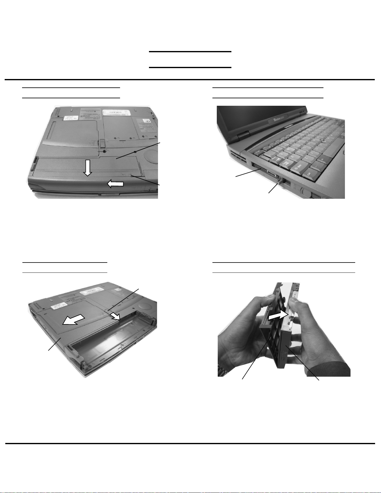
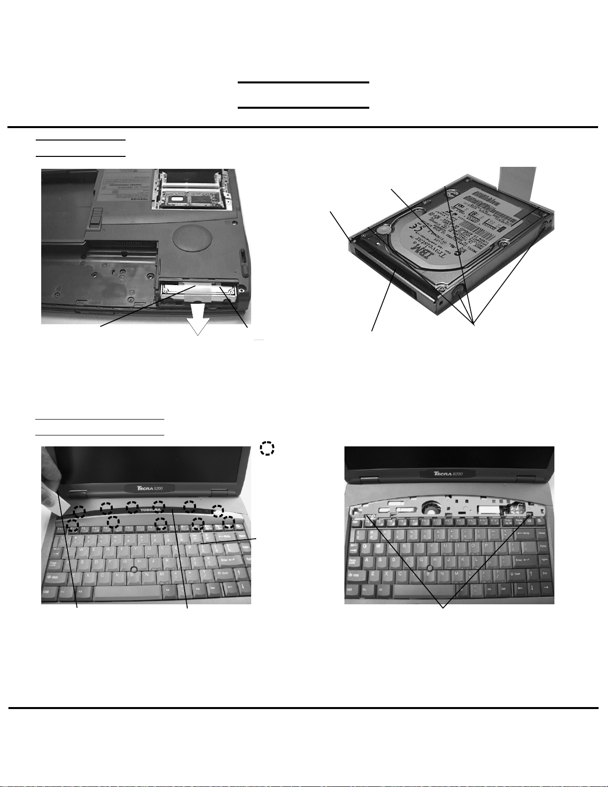
BATTERY PACK REMOVAL
Battery
Pack
Release
lever
1. Turn the computer upside down as shown.
2. Slide the battery release lever in the direction of the
arrow.
3. Slide the battery assembly forward and out of the
battery bay.
SELECT BAY REMOVAL
OPTIONAL PC CARD REMOVAL
PC card
Eject button
1. Pull out the eject button of the PC card to be
removed.
2. Press firmly to eject the PC card.
3. Grasp the PC card and remove it.
NOTE: Before removing any PCMCIA device, make
sure it is “STOPPED” in the PC Card Manager.
DVD-ROM/CD-RW DRIVE DISASSEMBLY
Release
lever
Select bay
device
1. Turn the computer upside down.
2. Slide the release lever in the direction of the arrow.
3. Pull out the select bay device in the direction of the
arrow.
Selectable bay cover
1. Remove the selectable bay cover.
CD-ROM
TOSHIBA
Tough Enough for Today’s World.
Download service manual and resetter printer at http://printer1.blogspot.com
Page 4
FIELD REPLACEABLE UNIT DOCUMENTATION
TM
Tecra
8200 Series
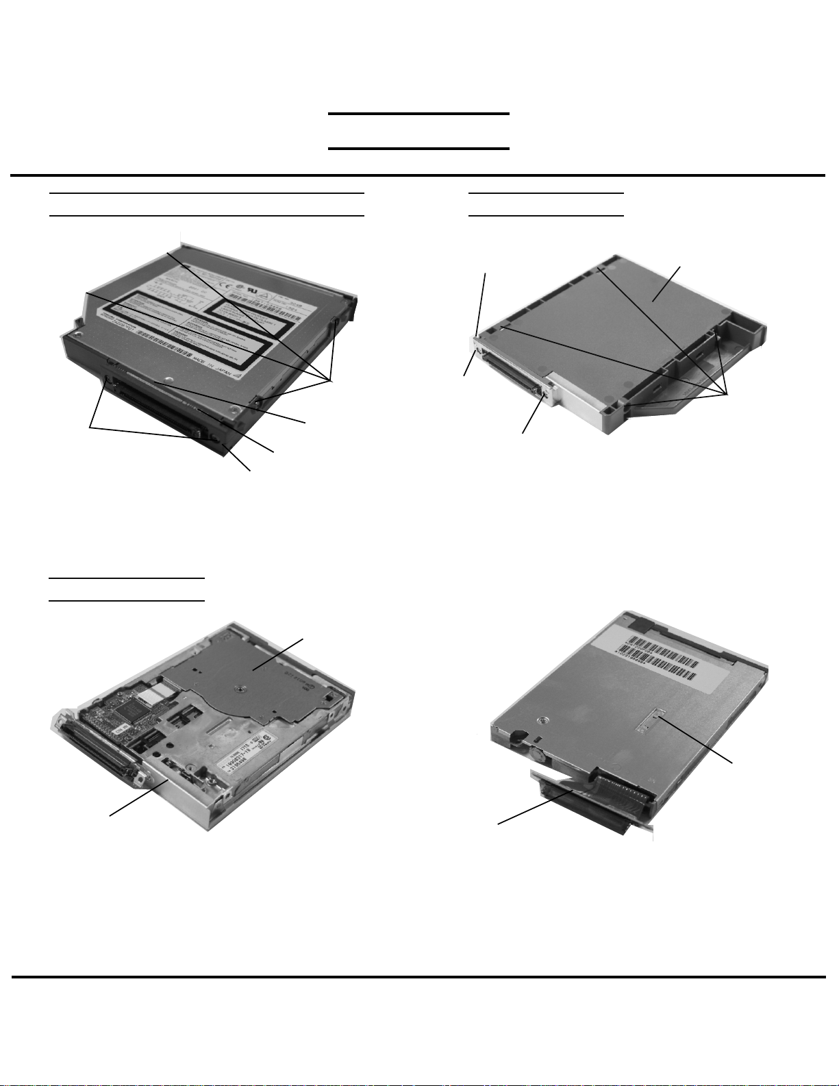
DVD-ROM/CD-RW DRIVE DISASSEMBLY
M2x3 black
screws
M2x8 black
screws
Connector cover
2. Remove four M2x4 black screws
3. Remove the frame.
4. Remove two M2x8 silver screws.
5. Remove the spacer, connector, and the connector
cover from the CD/DVD ROM drive.
FDD DISASSEMBLY
Spacer
Connector
FDD DISASSEMBLY
Connector cover
M2x4
silver
screw
M2x6 silver screw
1. Remove the following six screws from the Select bay
module:
- Four M2.5x4 black screws
- One M2x6 silver screw
- One M2x4 silver screw.
2. Remove the connector cover and the plastic cover..
Plastic cover
M2x4 black
screws
FDD bracket
3. Remove the FDD from the FDD bracket.
TOSHIBA
FDD
FDD
Connector Flexible cable
4. Disconnect the connector flexible cable from the
FDD.
NOTE: The brackets, flexible cable and the screws
are separate parts.Please DO NOT return them
to TOSHIBA.
Tough Enough for Today’s World.
Download service manual and resetter printer at http://printer1.blogspot.com
Page 5
FIELD REPLACEABLE UNIT DOCUMENTATION
TM
Tecra
8200 Series
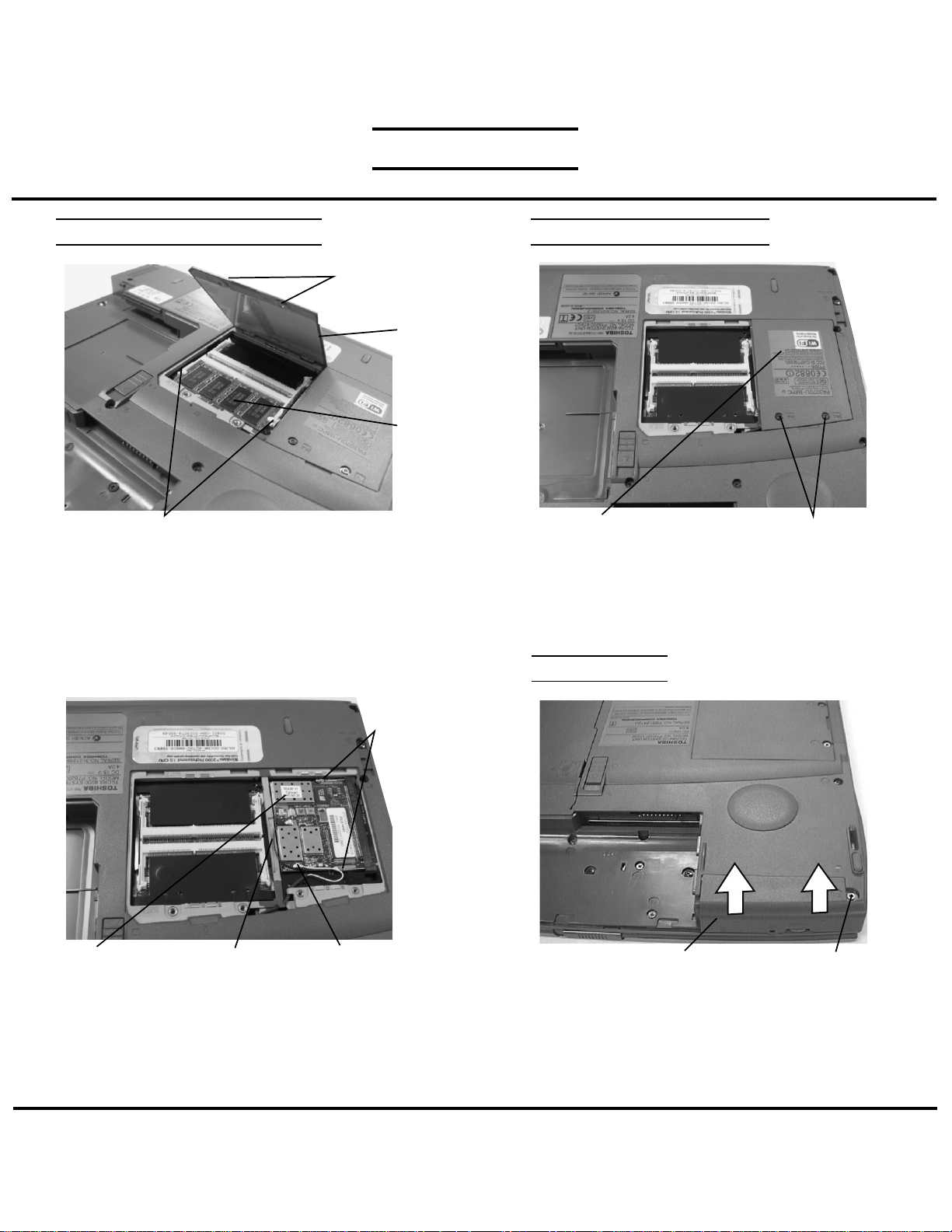
MEMORY MODULE REMOVAL WIRELESS LAN REMOVAL
M2.5x4 black
flat head screws
Memory
cover
Memory
module
Memory clips
1. Turn the computer upside down.
2. Remove two M2.5x4 black flat head screws and
remove the memory cover.
3. Spread the memory clips outward and pull the memory
module out of the connector on a 45 degree angle.
Mini-PCI
connector
clips
Wireless
LAN card
3. Disconnect the Black and White coax from PJ12 and
PJ13.
4. Spread the Mini-PCI connector clips and pull the
Wireless LAN card out of the connector about
45 degree angle.
Black coax cable
White coax cable
Mini PCI cover
1. Turn the computer upside down.
2. Remove two M2.5x4 security torx screws securing
the Wireless LAN cover and lift out the cover.
HDD REMOVAL
HDD cover
1. Turn the computer upside down.
2. Remove one M2.5x4 black flat head screws
securing HDD cover
3. Push up the raised nubs to remove the HDD cover.
M2.5x4 security torx screw
M2.5x4 black
flat head screws
TOSHIBA
Tough Enough for Today’s World.
Download service manual and resetter printer at http://printer1.blogspot.com
Page 6
FIELD REPLACEABLE UNIT DOCUMENTATION
HDD REMOVAL
TM
Tecra
8200 Series
HDD
HDD
bracket
Plastic Tab
4. Unfold the plastic tab and pull to remove the HDD
from the bay.
KEYBOARD REMOVAL
Case separator
1. Open the display panel.
2. Using the case separator, unlatch the keyboard holder
at the top of the keyboard.
Keyboard holder
HDD pack
Latch
Keyboard
HDD connector
5. Remove four M3x4 flat head brass screws securing
the HDD to the bracket and lift the drive out of the
bracket.
6. Unplug the HDD connector from the drive.
M2.5x2.8 black screws
3. Remove two M2.5x2.8 black screws securing the
keyboard.
4. Lift out the keyboard and set it as shown above.
5. Disconnect the keyboard cable from PJ580 on the
system board.
M3x4 flat head brass screws
TOSHIBA
Tough Enough for Today’s World.
Download service manual and resetter printer at http://printer1.blogspot.com
Page 7
FIELD REPLACEABLE UNIT DOCUMENTATION
TM
Tecra
8200 Series
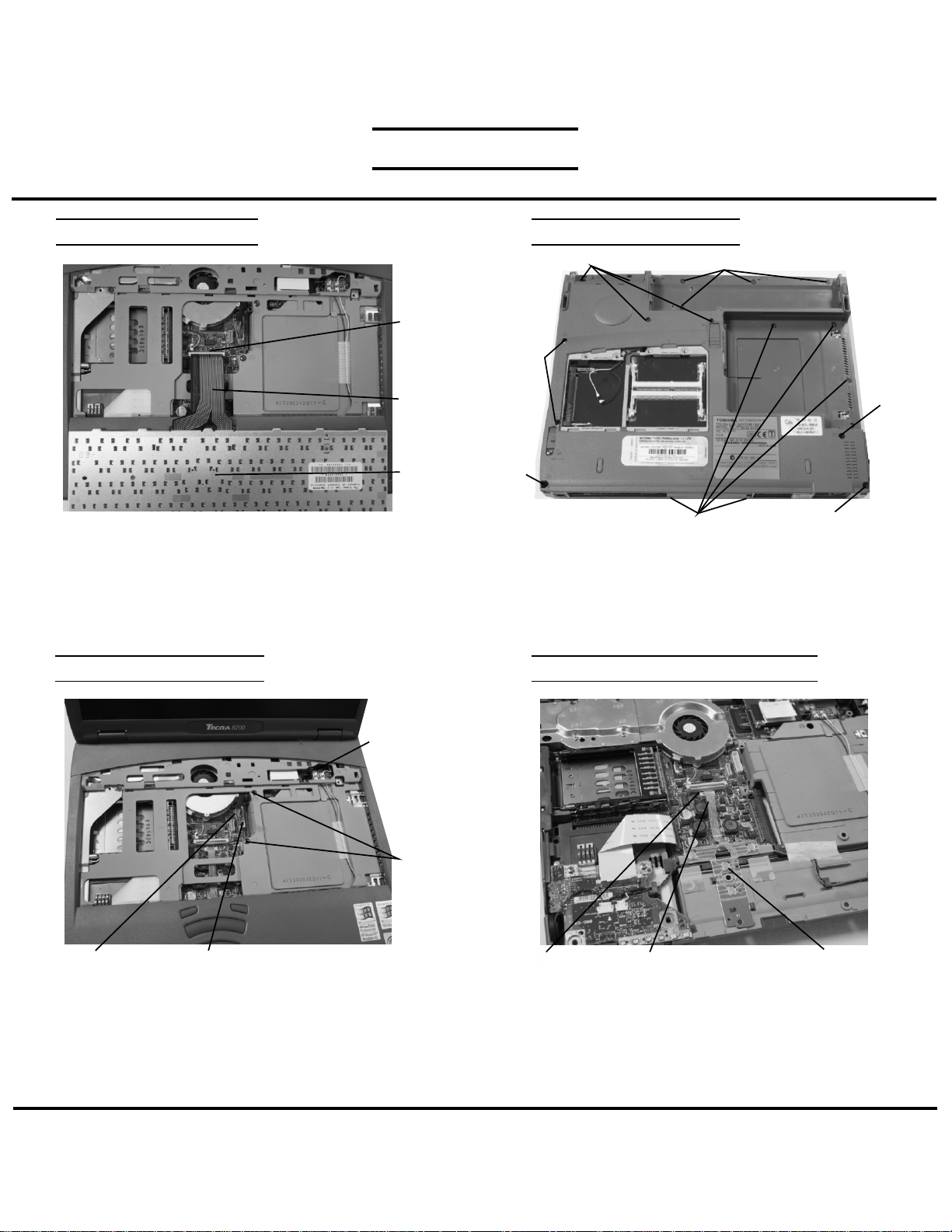
KEYBOARD REMOVAL
PJ720
Keyboard
cable
Keyboard
3. Lift out the keyboard and set it on the palmrest.
4. Disconnect the keyboard cable from PJ720 and lift
out the keyboard.
TOP COVER REMOVAL
TOP COVER REMOVAL
M2.5x6 black screw
M2.5x16
black
screws
M2.5x6
black
screw
M2.5x4 black flat head screws
1. Turn the computer upside down and remove the
following screws:
-4 M2.5x2.8 black flat head screws
-5 M2.5x4 black flat head screws
-6 M2.5x6 black screws
-3 M2.5x16 black screws
M2.5x2.8 black flat head screws
M2.5x6 black screws
MEMBRANE SWITCH REMOVAL
M2.5x16
black
screw
Black/white
coax cable
M2.5x16
black
screws
PJ101
2. Turn the computer right side up and open the display.
3. Disconnect the display cable from PJ101 on the system
and the black/white coax cable from PJ93/92 on the
coax connector board.
4. Remove two M2.5x16 black screws from the keyboard
area.
5. Lift out the top cover assembly.
LCD/FL inverter cable
TOSHIBA
PJ730 Membrane
1. Disconnect the membrane switch cable from PJ730
on the sound board.
2. Lift out the membrane switch.
Membrane switch
cable
switch
Tough Enough for Today’s World.
Download service manual and resetter printer at http://printer1.blogspot.com
Page 8

FIELD REPLACEABLE UNIT DOCUMENTATION
TM
Tecra
8200 Series
SPEAKERS & MICROPHONE REMOVAL
Microphone
Left/Right
speaker
cable
PJ3
Left speaker
1. Lift the strip of glass tape securing the microphone and
speaker cables.
2. Disconnect the speaker cable from PJ961 and the
microphone cable from PJ964 on the sound board.
3. Remove the cables and lift out the speaker assemblies.
Rubber holders
cable
PJ4
Tape
Right
speaker
Microphone
COOLING MODULE REMOVAL
SOUND BOARD REMOVAL
Sound cable
PJ1
M2.5x4
brass
screws
1. Disconnect the sound cable from PJ407 on the
system board.
2. Remove two M2.5x4 screws securing the sound
board.
3. Lift out the sound board assembly.
4. Disconnect the sound cable from PJ1 on the
sound board.
Sound board
CPU REMOVAL
PJ407
Cooling
module
Fan cable
PJ202
M2x10 brass screws
1. Disconnect the fan cable from PJ202 on the system
board.
2. Remove four M2x10 brass screws securing the cooling
module.
3. Lift out the cooling module.
TOSHIBA
CPU
lock
Thermal
conductor
1. Peel off the thermal conductor.
Tough Enough for Today’s World.
Download service manual and resetter printer at http://printer1.blogspot.com
Page 9

FIELD REPLACEABLE UNIT DOCUMENTATION
TM
Tecra
8200 Series
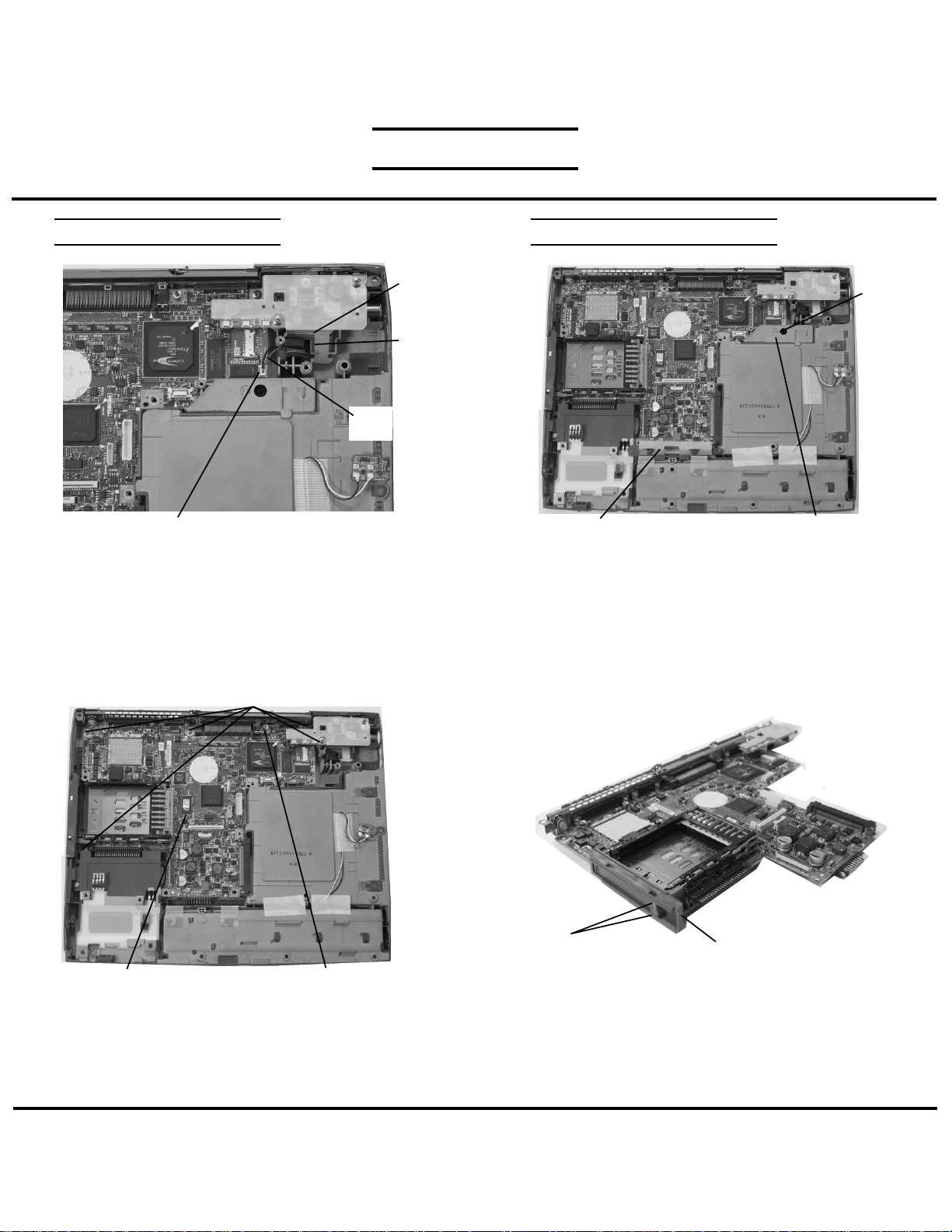
CPU REMOVAL
.
MODEM BOARD REMOVAL
LOCK
CPU lock
Modem
relay board
RJ11/RJ45
jack
OPEN
CPU lock
1. Rotate the CPU lock 180 degrees clockwise, to the
OPEN position, and lift the CPU out of the socket.
M2x5 silver screws
M2.5x4
brass
screw
M2x4 silver screws
1. Remove one M2.5x4 brass screw securing the Wireless
LAN antenna relay board and three M2x4 silver screws
securing the modem relay board.
2. Lift up the left side of the modem relay board to disconnect
from PJ610 on the system board and remove the modem
relay board and RJ11/RJ45 jack upward.
3. Disconnect the LAN cable from PJ150 on the system board.
Wireless LAN antenna relay board
TOSHIBA
Tough Enough for Today’s World.
Download service manual and resetter printer at http://printer1.blogspot.com
Modem cable
MDC
4. Remove two M2x5 silver screws securing the MDC
(modem daughter card).
5. Lift up the back of the MDC to disconnect it from
the modem relay board.
6. Disconnect the modem cable from the MDC.
Page 10
FIELD REPLACEABLE UNIT DOCUMENTATION
TM
Tecra
8200 Series
RTC BATTERY REMOVAL
RTC
battery
Plastic
shield
RTC battery
cable
PJ201
1. Disconnect the RTC battery cable from PJ201 on the
system board.
2. Unlatch the plastic shield and lift out the RTC battery.
SYSTEM BOARD REMOVAL
M2.5x6
black
screw
HDD connector cover
1. Remove one M2.5x6 black screw securing the
select Bay cover.
2. Remove the HDD connector cover.
Select Bay cover
M2.5x4 brass screws
System board
3. Remove four M2.5x4 brass screws and
one M2.5x4 hexagonal screw securing the
system board.
4. Lift out the system board.
M2.5x4 Hex screw
Eject buttons
1. Unfold the PC card eject buttons and remove the
PC card slot cover.
PC card slot cover
TOSHIBA
Tough Enough for Today’s World.
Download service manual and resetter printer at http://printer1.blogspot.com
Page 11

FIELD REPLACEABLE UNIT DOCUMENTATION
TM
Tecra
8200 Series
14.1” DISPLAY MASK REMOVAL
Latch
Display
mask
LCD
Mask seals
1. Remove two mask seals at the bottom corners of the
display assembly using a pair of fine-tipped tweezers.
2. Remove two M2.5x6 flat head brass screws securing
the display mask.
3. There are 23 latches securing the display mask.
Carefully insert your fingers between the mask and the
LCD panel and pry open the latches starting from the
bottom seven latches, to the five latches on the right
and left sides, ending with the six toplatches.
FL INVERTER AND 14.1” LCD REMOVAL
Plastic shield
Mask
seals
M2x4
brass
screws
LCD/FL cable
1. Lift the plastic shield.
2. Carefully lift up the FL inverter board and
disconnect the LCD/FL cable from CN1 and the
FL cable from CN2.
3. Remove four mask seals to expose four screws
securing the LCD module.
4. Remove four M2X4 brass screws securing the
LCD module.
5. Carefully rotate out the top of the LCD module
enough to access the display cable
6. Peel off the tape securing the LCD/FL cable and
disconnect the cable.
FL inverter board
LCD module
Mask
seals
M2x4
brass
screws
FL cable
TOSHIBA
Tough Enough for Today’s World.
Download service manual and resetter printer at http://printer1.blogspot.com
 Loading...