

Toshiba TEC CB-416-T3-QQ Owner's Manual
TEC Color Printer
CB-416-T3-QQ
Owner’s Manual

W e, TOSHIBA TEC Corporation of 570 Ohito Ohito-cho T agata-Gun Shizuoka-Ken 410-2323 JAP AN,
declare in our sole responsibility that this product has been tested and found to comply with the limits
for a Class A digital device, pursuant to Part 15 of the FCC Rules. These limits are designed to
provide reasonable protection against harmful interference when the equipment is operated in a
commercial environment. This accordance with the instruction manual, may cause harmful interference
to radio communications. Operations of this equipment in a residential area is likely to cause harmful
interference in which case the user will be required to correct the interference at his own expense.
(for USA only)
Changes or modifications not expressly approved by manufacturer for compliance could void the
user’s authority to operate the equipment.
“This Class A digital apparatus meets all requirements of the Canadian Interference-Causing Equipment
Regulations.”
“Cet appareil numérique de la classe A respecte toutes les exigences du Règlement sur le matériel
brouilleur du Canada.” (for CANADA only)
CAUTION:
1.This manual may not be copied in whole or in part without prior written permission of TOSHIBA
TEC.
2.The contents of this manual may be changed without notification.
3.Please refer to your local Authorized Service representative with regard to any queries you may
have in this manual.
Trademark:
• Microsoft, Windows, Windows NT, and the Windows Logo are either registered trademarks or
trademarks of Microsoft Corporation in the United States.
• All other brands and names are the property of their respective owners.
Copyright © 2000
by TOSHIBA TEC CORPORATION
All Rights Reserved
570 Ohito, Ohito-cho, Tagata-gun, Shizuoka-ken, JAPAN

Safety Precautions
i
Safety Precautions
Personal safety in handling or maintaining the equipment is extremely
important. Warnings and Cautions necessary for safe handling are
included in this manual. All warnings and cautions contained in this
manual should be read and understood before handling or maintaining
the equipment.
Do not attempt to effect repairs or modifications to this equipment.
If a fault occurs that cannot be rectified using the procedures described
in this manual, turn off the power, unplug the machine, then contact
your authorized TOSHIBA TEC representative for assistance.
This symbol indicates warning items (including cautions).
Specific warning contents are drawn inside the symbol.
(The symbol on the left indicates a general caution.)
This symbol indicates prohibited actions (prohibited items).
Specific prohibited contents are drawn inside or near the
symbol.
(The symbol on the left indicates “no disassembling”.)
This symbol indicates actions which must be performed.
Specific instructions are drawn inside or near the symbol.
(The symbol on the left indicates “disconnect the power cord plug
from the outlet”.)
Safety Summary
Meanings of Symbols
Safety Precautions
ii
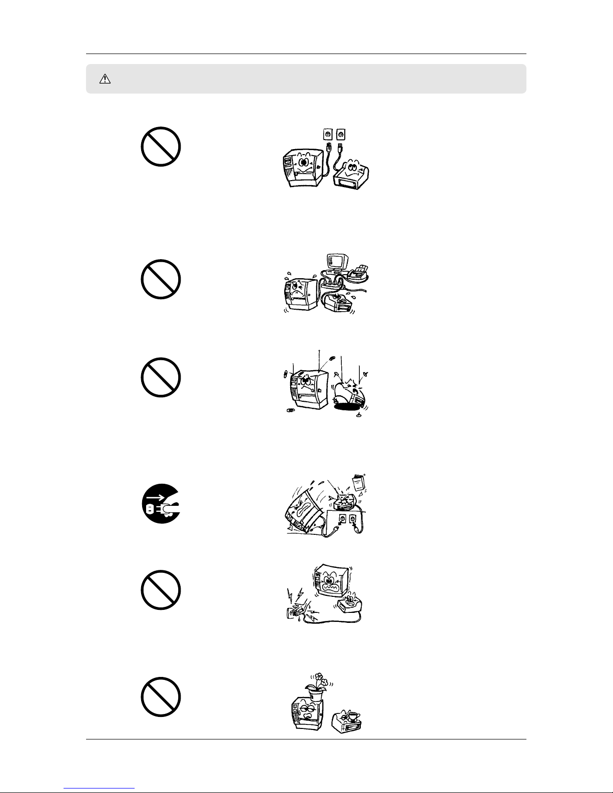
WARNING
This indicates that there is the risk of death or serious injury if the
machines are improperly handled contrary to this indication.
■ Do not use voltages other than the voltage (AC) specified on the
rating plate, as this may cause fire or electric shock.
■ If the machines share the same outlet with any other electrical
appliances which consume large amounts of power, the voltage
will fluctuate widely each time these appliances operate. Be sure
to provide an exclusive outlet for the machine as this may cause
the machines to malfunction.
■ Do not insert or drop metal, flammable or other foreign objects
into the machines through the ventilation slits, as this may cause
fire or electric shock.
■ If the machines are dropped or their cabinets damaged, first turn
off the power switches and disconnect the power cord plugs from
the outlet, and then contact your authorized TOSHIBA TEC
representative for assistance. Continued use of the machine in
that condition may cause fire or electric shock.
■ Do not plug in or unplug the power cord plug with wet hands as
this may cause electric shock.
■ Do not place metal objects or water-filled containers such as flower
vases, flower pots or mugs, etc. on top of the machines. If metal
objects or spilled liquid enter the machines, this may cause fire or
electric shock.
Any other than the specified AC voltage
is prohibited.
Prohibited
Disconnect the plug.
Prohibited
Prohibited
Prohibited
Safety Precautions
iii
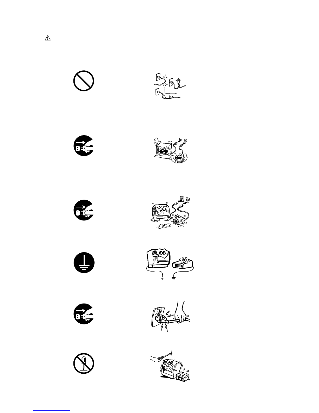
WARNING (Cont.)
■ Do not cut, damage or modify the power cords. Also, do not
place heavy objects on, pull on, or excessively bend the cords, as
this may cause fire or electrical shock.
■ Continued use of the machines in an abnormal condition such as
when the machines are producing smoke or strange smells may
cause fire or electric shock. In these cases, immediately turn off
the power switches and disconnect the power cord plugs from the
outlet. Then, contact your authorized TOSHIBA TEC representative
for assistance.
■ If foreign objects (metal fragments, water, liquids) enter the
machines, first turn off the power switches and disconnect the
power cord plugs from the outlet, and then contact your authorized
TOSHIBA TEC representative for assistance. Continued use of
the machine in that condition may cause fire or electric shock.
■ Ensure that the equipment is properly grounded. Extension cables
should also be grounded. Fire or electric shock could occur on
improperly grounded equipment.
■ When unplugging the power cords, be sure to hold and pull on
the plug portion. Pulling on the cord portion may cut or expose
the internal wires and cause fire or electric shock.
■ Do not remove covers, repair or modify the machine by yourself.
Y ou may be injured by high voltage, very hot parts or sharp edges
inside the machine.
No disassembling.
Prohibited
Disconnect the plug.
Disconnect the plug.
Disconnect the plug.
Connect a grounding wire.

iv
CAUTION
This indicates that there is the risk of personal injury or damage to
objects if the machine is improperly handled contrary to this
indication.
The following precautions will help to ensure that this machine will
continue to function correctly.
• Try to avoid locations that have the following adverse conditions:
* Temperatures out of the specification
* Direct sunlight * High humidity
* Shared power source * Excessive vibration
* Dust/Gas
• The cover should be cleaned by wiping with a dry cloth or a cloth
slightly dampened with a mild detergent solution. NEVER USE
THINNER OR ANY OTHER VOLATILE SOLVENT on the
plastic covers.
• USE ONLY TOSHIBA TEC SPECIFIED paper and ribbons.
• DO NOT STORE the paper or ribbons where they might be exposed
to direct sunlight, high temperatures, high humidity , dust, or gas.
• Ensure the printer is operated on a level surface.
• Any data stored in the memory of the printer could be lost during
a printer fault.
• Try to avoid using this equipment on the same power source as
high voltage equipment or equipment likely to cause electrical
interference.
• Unplug the machine whenever cleaning or working inside it.
• Keep the work environment static free.
• Do not place heavy objects on top of the machines, as these items
may become unbalanced and fall causing injury.
• Do not block the ventilation slits of the machines, as this will
cause heat to build up inside the machines and may cause fire.
• Do not lean against the machine. It may fall and cause injury.
• Care must be taken not to injure yourself with the printer paper cutter.
• Unplug the machine when it is not used for a long period of time.
• Utilize our maintenance services.
After purchasing the machine, contact your authorized TOSHIBA
TEC representative for assistance once a year to have the inside
of the machine cleaned. Otherwise, dust will build up inside the
machines and may cause a fire or a malfunction. Cleaning is
particularly effective before humid rainy seasons.
• Our preventive maintenance service performs the periodic checks
and other work required to maintain the quality and performance
of the machines, preventing accidents beforehand.
For details, please consult your authorized TOSHIBA TEC
representative for assistance.
• Do not expose the machines to insecticides or other volatile
solvents. This will cause the cabinet or other parts to deteriorate
or cause the paint to peel.
Request Regarding
Maintenance
Safety Precautions

v
Contents
1. Product Overview ................................................................................................................................................... 1
1.1 Introduction ...................................................................................................................................................... 1
1.2 Features ............................................................................................................................................................ 1
1.3 Unpacking ........................................................................................................................................................ 1
1.4 Accessories and Options ................................................................................................................................. 2
1.4.1 Accessories ............................................................................................................................................. 2
1.4.2 Cool Release Enhancement Kit ............................................................................................................... 3
1.4.3 Options .................................................................................................................................................... 3
1.5 Appearance ...................................................................................................................................................... 4
1.5.1 Dimensions .............................................................................................................................................. 4
1.5.2 Front View ............................................................................................................................................... 4
1.5.3 Rear View ................................................................................................................................................ 4
1.5.4 Operation Panel ...................................................................................................................................... 5
1.5.5 Interior ..................................................................................................................................................... 5
2. Printer Installation .................................................................................................................................................. 6
2.1 Installing the Accessories ................................................................................................................................. 6
2.1.1 Fan Filters ................................................................................................................................................ 6
2.1.2 Media Slide ............................................................................................................................................. 6
2.1.3 Supply Shaft Holder ................................................................................................................................ 6
2.2 Connecting the Printer to Your Computer ........................................................................................................ 7
2.3 Connecting the Power Cord ............................................................................................................................. 8
2.4 Turning on/off the Printer.................................................................................................................................. 9
2.4.1 Turning on the Printer .............................................................................................................................. 9
2.4.2 Turning off the Printer ............................................................................................................................ 10
2.5 Loading the Media .......................................................................................................................................... 11
2.5.1 Additional Information ........................................................................................................................... 16
2.6 Sensor Adjustments ....................................................................................................................................... 17
2.6.1 Black Mark Sensor ................................................................................................................................ 17
2.6.2 Feed Gap Sensor .................................................................................................................................. 18
2.6.3 Media Sensor Sensitivity Adjustment ................................................................................................... 19
2.7 Loading the Ribbons (for Hot Release Ribbons) ............................................................................................ 21
2.7.1 Ribbon Positions ................................................................................................................................... 21
2.7.2 Loading Procedure ................................................................................................................................ 21
2.8 Loading the Ribbons (for Cold Release Ribbons) .......................................................................................... 24
2.8.1 Precautions ........................................................................................................................................... 24
2.8.2 Installing the Ribbon Plate .................................................................................................................... 25
2.8.3 Installing the SP Ribbon Guides ........................................................................................................... 26
2.8.4 Installing the Ribbon Tension Sheet ...................................................................................................... 27
2.8.5 Loading the Cold Release Ribbons....................................................................................................... 28
3. Printing .................................................................................................................................................................. 29
3.1 Installing the Printer Driver ............................................................................................................................. 29
3.1.1 System Requirements ........................................................................................................................... 29
3.1.2 Installation Procedure (For Windows
®
98) .............................................................................................. 29
3.1.3 Uninstalling the Printer Driver................................................................................................................ 35
3.2 Properties ....................................................................................................................................................... 37
3.2.1 Displaying Printer Properties ................................................................................................................. 37
3.2.2 Summary of Properties ......................................................................................................................... 38
3.3 Page Setup ..................................................................................................................................................... 39
3.3.1 Selecting a label size ............................................................................................................................. 39
3.3.2 Creating a new label size ...................................................................................................................... 40
3.3.3 Orientation ............................................................................................................................................. 41
3.3.4 Miscellaneous ....................................................................................................................................... 42
3.4 Graphics ......................................................................................................................................................... 46
3.4.1 Dithering ................................................................................................................................................ 46
3.4.2 Intensity ................................................................................................................................................. 47
3.4.3 Color ...................................................................................................................................................... 47
3.4.4 Color Registration ................................................................................................................................. 47
3.4.5 Spot Color Setup................................................................................................................................... 49
3.4.6 Spot Color Printing ................................................................................................................................ 50
3.5 Bar Fonts ........................................................................................................................................................ 51
3.5.1 Specifying a New Font Style ................................................................................................................. 52
Table of Contents
Table of Contents

vi
3.6 Stock .............................................................................................................................................................. 54
3.6.1 Print Method.......................................................................................................................................... 54
3.6.2 Sensor ................................................................................................................................................... 54
3.6.3 Label Gap .............................................................................................................................................. 54
3.6.4 Issue Settings ........................................................................................................................................ 55
3.6.5 Fine Adjustment .................................................................................................................................... 56
3.7 Options ........................................................................................................................................................... 57
3.7.1 Transfer Mode ....................................................................................................................................... 57
3.7.2 Print Density Adjustment....................................................................................................................... 57
3.8 Device Settings .............................................................................................................................................. 58
3.8.1 Maintenance .......................................................................................................................................... 59
3.8.2 Testing ................................................................................................................................................... 59
3.9 Print Test ......................................................................................................................................................... 60
3.9.1 Procedures ............................................................................................................................................ 60
3.10 Printing a Label .............................................................................................................................................. 61
4. Online Mode .......................................................................................................................................................... 64
4.1 Operation Panel.............................................................................................................................................. 64
4.2 Operation........................................................................................................................................................ 65
4.3 Reset .............................................................................................................................................................. 65
5. Maintenance ......................................................................................................................................................... 66
5.1 Cleaning ......................................................................................................................................................... 66
5.1.1 Print Head/Platen .................................................................................................................................. 66
5.1.2 Pinch Roller/Feed Roller/Media Guide .................................................................................................. 67
5.1.3 Fan Filters .............................................................................................................................................. 67
5.1.4 Covers and Panels ................................................................................................................................ 68
5.1.5 Ribbon Modules .................................................................................................................................... 68
6. Troubleshooting .................................................................................................................................................... 69
6.1 Error Messages .............................................................................................................................................. 69
6.2 Possible Problems.......................................................................................................................................... 71
6.3 Removing Jammed Media ............................................................................................................................. 72
6.3.1 From the Pinch Roller Unit .................................................................................................................... 72
6.3.2 From the Print Head Block .................................................................................................................... 72
6.4 When the Ribbon is Torn Apart ...................................................................................................................... 73
Appendix 1 Specifications......................................................................................................................................... 74
A1.1 Printer ............................................................................................................................................................. 74
A1.2 Options ........................................................................................................................................................... 75
A1.3 Media.............................................................................................................................................................. 75
A1.3.1 Media Type ............................................................................................................................................ 75
A1.3.2 Detection Area of the Transmissive Sensor .......................................................................................... 76
A1.3.3 Detection Area of the Reflective Sensor ............................................................................................... 77
A1.3.4 Effective Print Area ................................................................................................................................ 77
A1.4 Ribbon ............................................................................................................................................................ 78
Appendix 2 DIP Switches .......................................................................................................................................... 79
A2.1 DIP Switch A .................................................................................................................................................. 80
A2.2 DIP Switch B .................................................................................................................................................. 81
A2.3 Ribbon Near End Detection ........................................................................................................................... 82
Appendix 3 Quick Reference for Printing ................................................................................................................ 83
Appendix 4 Message and LED .................................................................................................................................. 86
Appendix 5 System Mode.......................................................................................................................................... 88
A5.1 Operation Panel.............................................................................................................................................. 88
A5.2 Overview......................................................................................................................................................... 89
A5.3 Self-Diagnostic Test ....................................................................................................................................... 91
A5.4 Parameter Setting .......................................................................................................................................... 92
A5.5 Test Print ....................................................................................................................................................... 101
A5.6 RAM Clear .................................................................................................................................................... 104
A5.7 Additional Information .................................................................................................................................. 106
A5.7.1 Self-Diagnostic Test Result Sample and Descriptions ........................................................................ 106
A5.7.2 Maintenance Counter/Parameter Check Print Sample and Descriptions ........................................... 107
A5.7.3 Cut Operation Example ....................................................................................................................... 108
A5.7.4 Pulse Motor Speed ............................................................................................................................. 108
A5.7.5 X-Coordinate Fine Adjustment ............................................................................................................ 108
A5.7.6 Magnified Views of Slant Line Pattern ................................................................................................ 108
A5.7.7 Initial Values after Clearing the Maintenance Counter (MAINTE.CNT.CLEAR) .................................... 109
A5.7.8 Initial Values after Clearing the Parameter (PARAMETER CLEAR)...................................................... 110
A5.7.9 Initial Values after Clearing the Print Distance (PRINT STEP CLEAR) ................................................. 111
Appendix 6 Interface................................................................................................................................................ 112
Table of Contents

Chapter 1 Product Overview
1
1. Product Overview
1.1 Introduction
Thank you for choosing the TOSHIBA TEC CB-416-T3 color printer .
This Owner’s Manual describes printer setup and installation
procedures, printer properties, settings and adjustments, and
maintenance information. Thus it should be read carefully to help
gain maximum performance and life from the printer. For further
information please refer to this manual and keep it safe for future
reference.
The CB-416-T3 color printer has the following features:
• High-speed, quality printing. The printer utilizes Edge Heads that
support the high-performance Hot Release Ribbons to produce a
maximum print speed of approximately 6 in/s (150 mm/s). In
addition, the Cool Release Enhancement Kit is supplied as an
accessory, and allows the popular Cold Release Ribbons to be
loaded.
•Fine, sharp color printing. The printer utilizes four high-resolution
(305 dpi) print heads, and uses both basic process color ribbons
of yellow, cyan, magenta and black to produce up to 260,000
colors, and a variety of spot color ribbons for solid printing.
• A variety of printer fonts and bar code fonts are built into the
printer to help create a unique colored label.
• Cost efficiency. The automatic ribbon saver is standard and allows
for conservation of individual ribbons. In addition, the media
back feed capability allows you to avoid wasting the media.
Unpack the printer as per the Unpacking Instructions packed with
the printer.
Important!
• Check for damage or scratches on the printer.
However, please note that TOSHIBA TEC shall have no
liability of any damage of any kind sustained during
transportation of the product.
• Keep the cartons and pads for future transportation of the
printer.
1.2 Features
1.3 Unpacking
Chapter 1 Product Overview
2
1.4 Accessories and
Options
When unpacking the printer, please make sure all accessories are
packed with the printer.
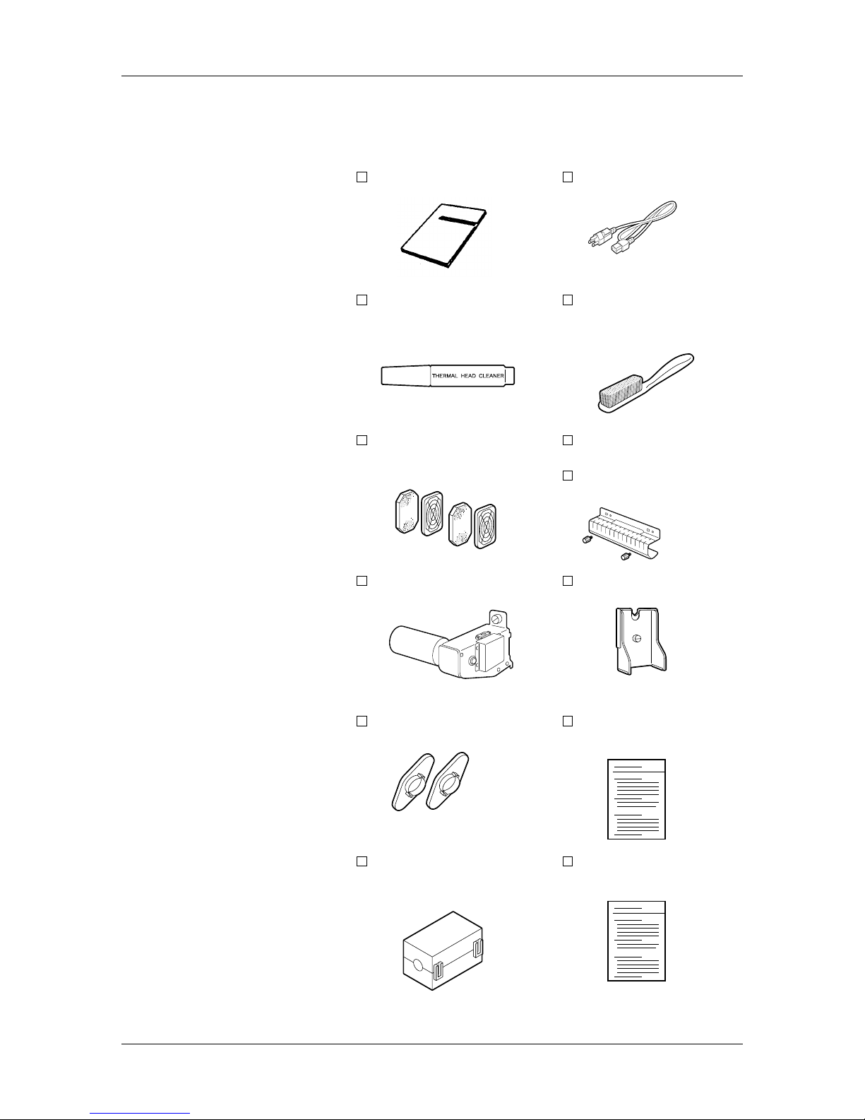
1.4.1 Accessories
Owner’s Manual (1 pc.)
Thermal Head Cleaner (1 pc.)
(24089500013)
Fan Filter (2 sets.)
(FMBB0046401)
Supply Shaft Holder (1 pc.)
(FMBD 0038901)
Supply Roll Holder (2 pcs.)
(FMHD0007502)
Ferrite Core (1 pc.)
(HGA-0068001)
*Used for RS-232C
Power Cord (1 pc.)
(FBC B0030202)
Feed Roller Brush (1 pc.)
(FMQB0047001)
*To be used exclusively for
the Feed Roller
Media Slide (1 pc.)
(FMCC 0032001)
Black Screw (2 pcs.)
(HAA-0007002)
Supply Shaft Holder Stand
(FMBB0047401)
Unpacking Instructions
Color Print Sample (1 pc.)
✓
(1pc.)
(1 pc.)
Chapter 1 Product Overview
3
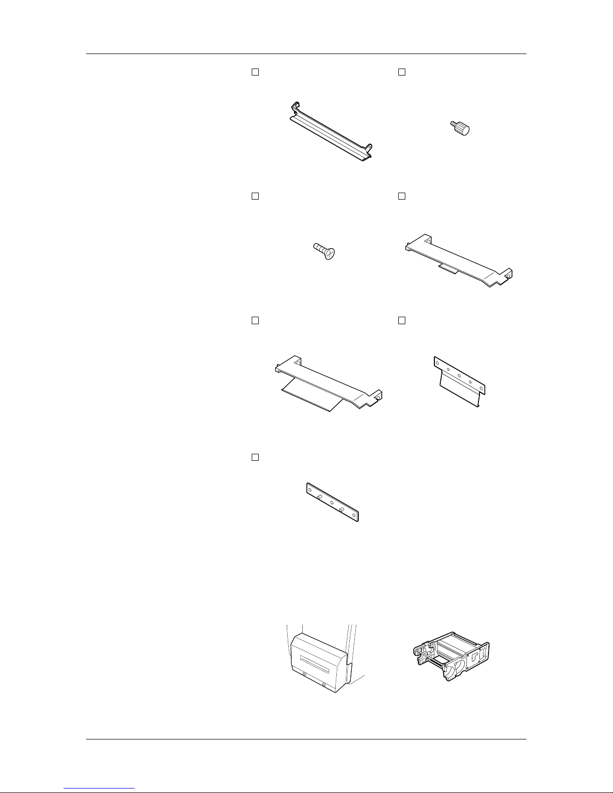
1.4.2 Cool Release
Enhancement Kit
Ribbon Plate (4 pcs.)
(FMCB 0095301)
D-3x5 Screw (12 pcs.)
(X0140305130)
SP Ribbon Guide (B) (3 pcs.)
(FMCB0095501)
Sheet Fixing Plate (4 pcs.)
(FMEB0116901)
Mounting Screw (4 pcs.)
(FMDB 0079501)
SP Ribbon Guide
(A) (1 pc.)
(FMCB0095601)
Ribbon T ension Sheet
(FMQC0035901)
1.4.3 Options
The following two options are available for the CB-416-T3 color
printer:
• The CB-1204-QM Cutter Module, which is used to cut media
repeatedly.
• The CB-1004-QM Ribbon Module, to be used as a spare ribbon
module.
(4 pcs.)
Cutter Module Ribbon Module
Chapter 1 Product Overview
4
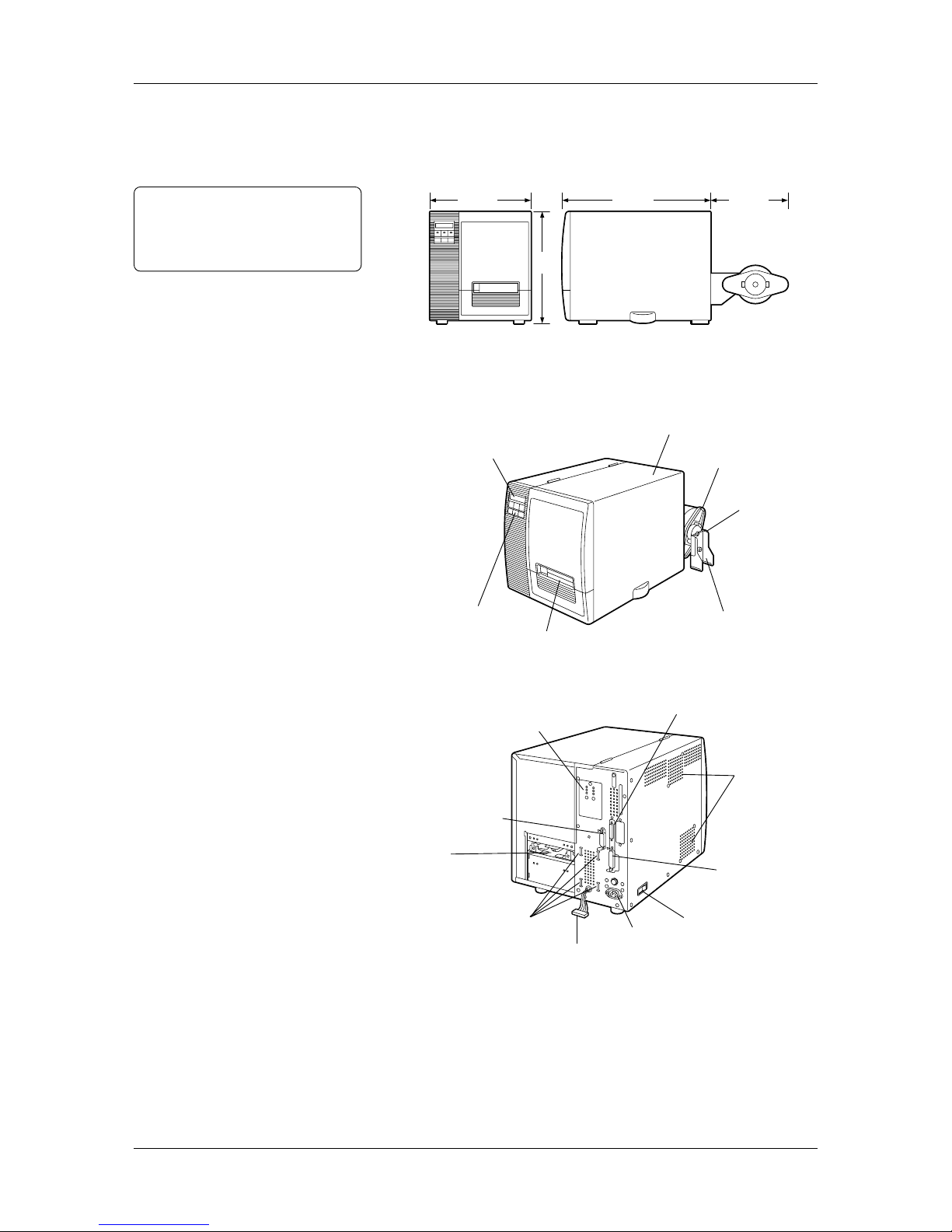
1.5 Appearance
1.5.1 Dimensions
Note:
Depth is 34.4 inches (875mm) when
the Cutter Module is installed on the
printer.
20.4(520)
11.0(280)
13.7(350)
15.1
(385)
Dimensions in inches + (mm)
1.5.2 Front View
1.5.3 Rear View
Message Display (LCD)
Top Cover
Supply Roll Holder
Supply Shaft Holder
Supply Shaft Holder Stand
Operation Panel
Media Outlet
Air Vents
(Cooling Fans)
Serial Interface Connector
(RS-232C)
Parallel Interface
Connector
(Centronics)
Power Switch
AC Power Inlet
Expansion I/O
Interface Connector
Media Sensor Adjuster
Supply Shaft Holder Slots
Harness
Media Inlet
The names of the parts or units introduced in this section are used in
the following chapters.
Chapter 1 Product Overview
5
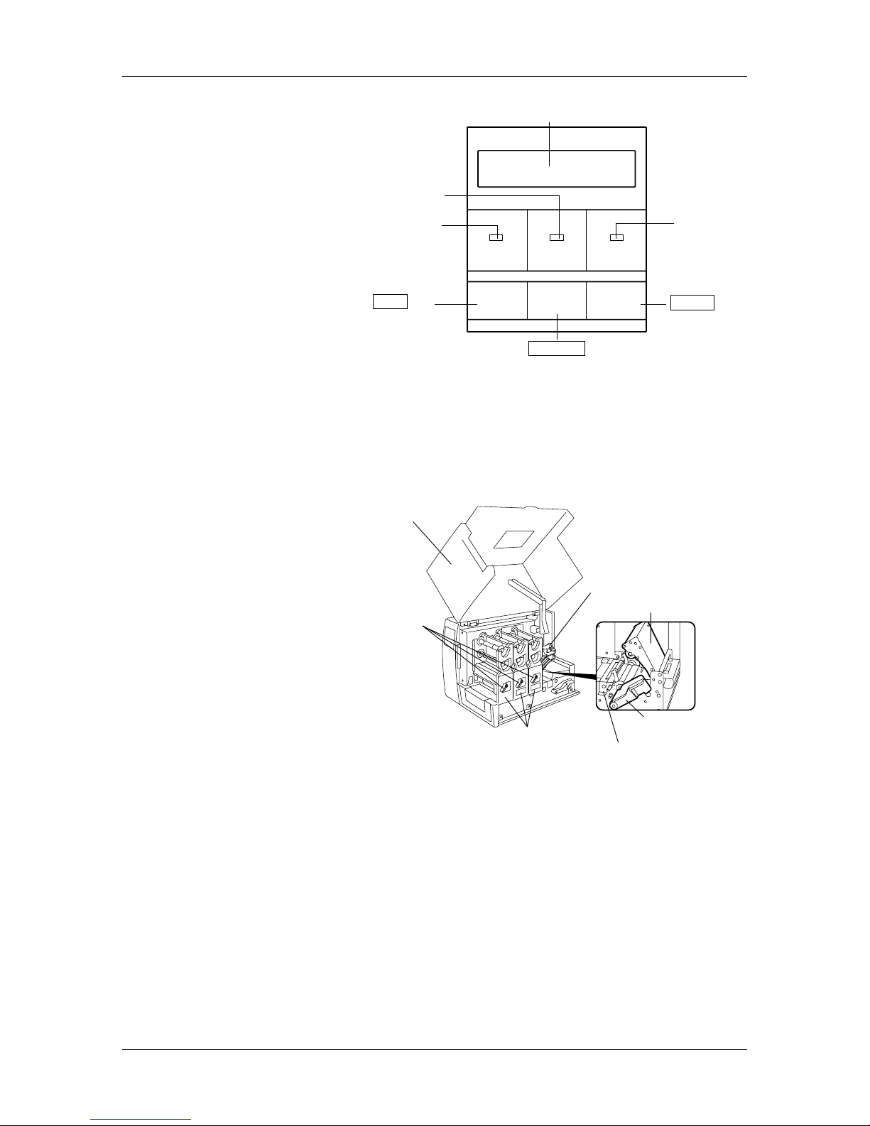
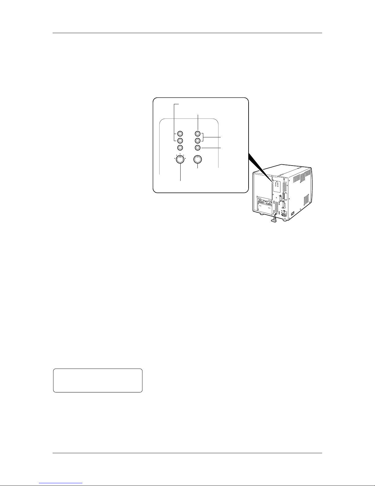
1.5.4 Operation Panel
Please see Appendix 3 for further information about the Operation
Panel.
POWER ON LINE ERROR
FEED RESTART PAUSE
Message Display (LCD)
ON LINE LED
(Green)
POWER LED
(Red)
ERROR LED
(Green)
FEED Key
RESTART Key
PAUSE Key
1.5.5 Interior
Print Head Block
Pinch Roller Unit
Pinch Roller Lever
Media Pressure Plate
Ribbon Module
Head Lever
Top Cover
Chapter 2 Printer Installation
6
2. Printer Installation
This chapter describes in detail how to set up the printer to get ready
for printing.
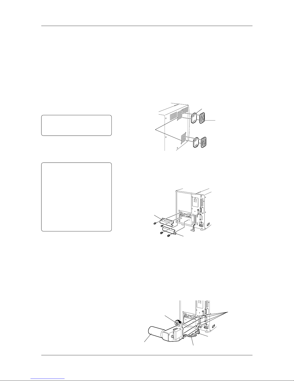
2.1 Installing the
Accessories
First install the accessories on the printer.
1
Unpack the Fan Filters.
2
Mount the Fan Filters over the Air Vents.
2.1.1 Fan Filters
Note:
Please clean the Filter Pads
periodically. See Section 5.1.3.
Attach the Media Slide with the two supplied black screws.
When loading a roll of labels, fit the Media Slide on the screw holes
above the Media Inlet.
or
When loading a roll of tags, fit the Media Slide on the screw holes
below the Media Inlet.
2.1.2 Media Slide
1
Connect the Supply Shaft Holder Harness to the harness attached
on the rear of the printer.
2
First hook the lower parts of the Supply Shaft Holder into the
lower two Supply Shaft Holder Slots on the rear of the printer.
Then fix the Supply Shaft Holder in place by tightening the screw .
T o remove the Supply Shaft Holder from the printer, just reverse the
installation procedure.
2.1.3 Supply Shaft Holder
Filter Pad
Filter Retainer
Air Vents
(Cooling Fans)
Media Slide (for tags)
Media Slide (for labels)
Harness
Supply Shaft Holder Harness
Supply Shaft Holder
Screw
Notes:
• Either a roll of labels or tags can
be loaded in the printer.
• In this Owner's Manual, labels and
tags are generically called
"media".
• TOSHIBA TEC recommends that
labels are rolled outside, and the tags
are r olled inside. The media loading
procedur e depends on which type of
media is going to be loaded. See
Section 2.5 for more detail.
Supply Shaft
Holder Slots
Chapter 2 Printer Installation
7
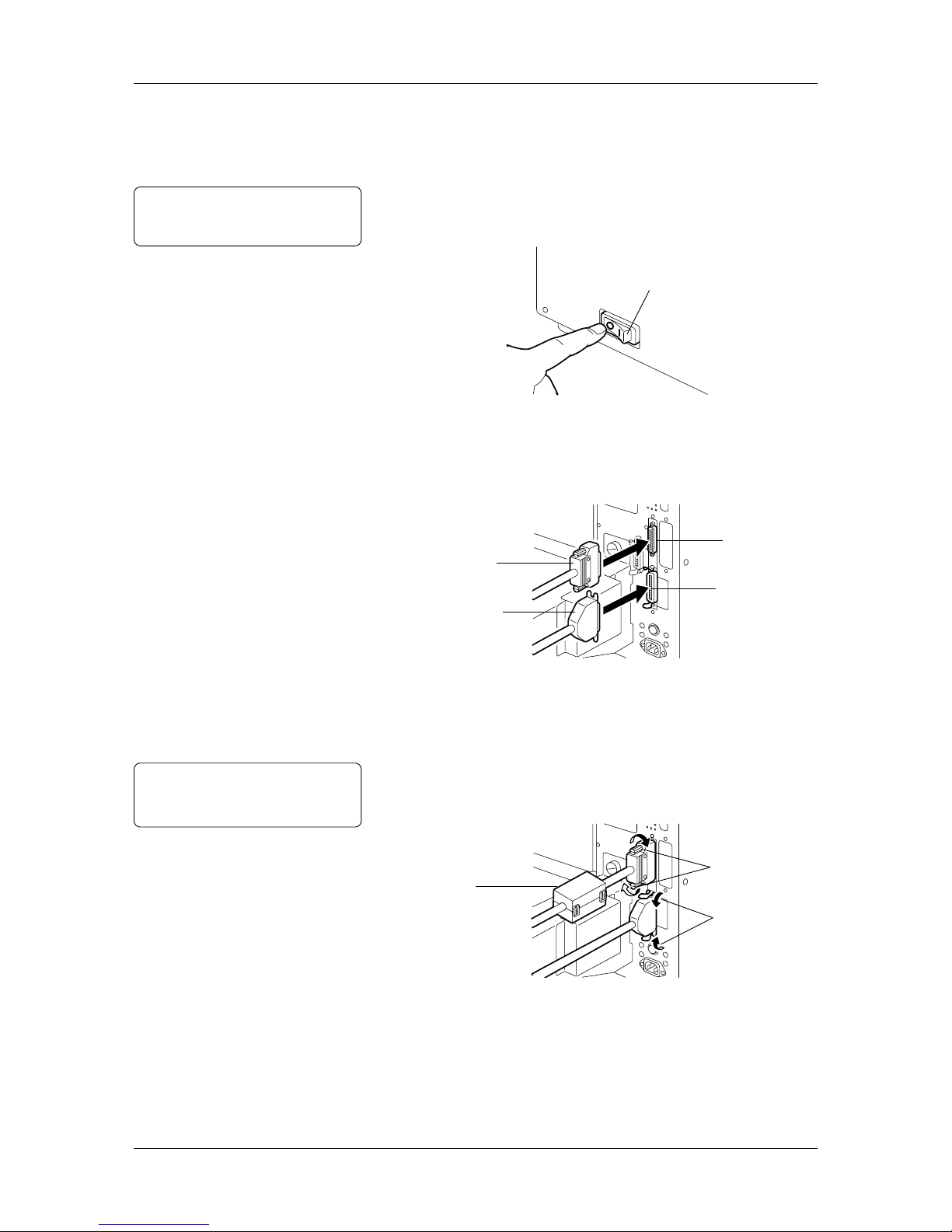
2.2 Connecting the
Printer to Your
Computer
The printer can be connected to any computer, since it supports both
serial and parallel interface cables. Before connecting the printer,
please make sure which interface cable will be used.
1
Be sure that both printer and computer are turned off.
(o) indicates OFF.
2
Connect the interface cable to the interface connector on the
printer. As illustrated below, connect the interface cable to either
of the interface connectors, depending on which interface cable
will be used.
3
Secure the cable with the clamps or screws.
4
When using the serial interface cable, attach the supplied ferrite
core to the cable.
5
Connect the interface cable to the interface connector on the
computer.
Power Switch
Serial Interface
Connector
Parallel Interface
Connector
Serial Interface
Cable
Parallel Interface
Cable
Screws
Clamps
Ferrite Core
(For Serial Interface
Cable)
Note:
The interface cable is not included
in the accessories.
Note:
Please refer to the user's manual of
the computer.
Chapter 2 Printer Installation
8
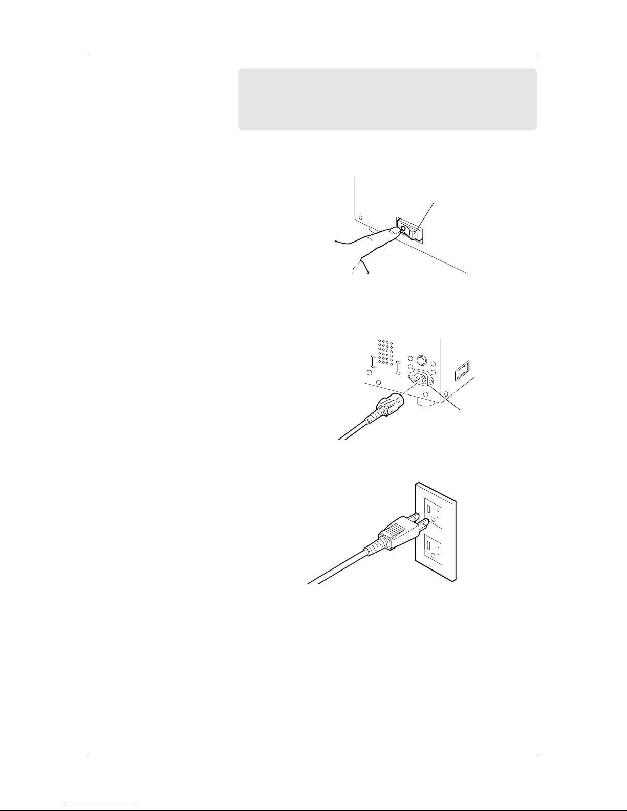
2.3 Connecting
the Power
Cord
CAUTION!
• Please turn off the printer before connecting the power cord,
as this may cause an electric shock or damage to the printer.
• Please use the supplied power cord only. Use of other cords
may cause an electric shock or a fire.
1
Be sure that both printer and computer are switched OFF.
(o) indicates OFF.
2
Connect the supplied power cord to the AC Power Inlet of the
printer.
3
Plug the power cord in an outlet.
Power Switch
AC Power Inlet

Chapter 2 Printer Installation
9
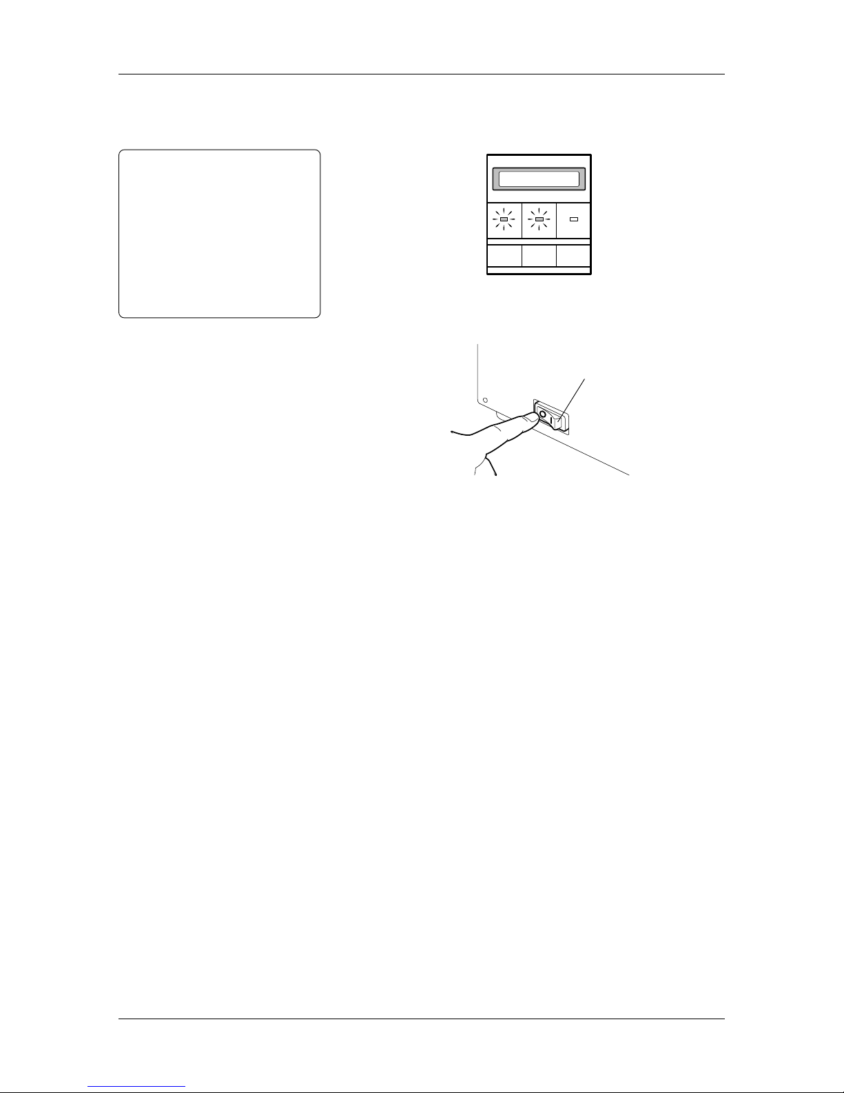
2.4 Turning on/off
the Printer
When turned on, the printer checks the print head and memory.
When turned off, the printer will lose data in non-volatile memory.
CAUTION!
Use the power switch to turn on/off the printer. Unplugging
the power cord for turning on/off the printer may cause a fire,
an electric shock, or damage to the printer.
Important!
When the printer is connected to the computer,
• Turn ON the printer before turning on the computer.
• Turn OFF the computer before turning off the printer.
1
Turn on the printer. ( ❘ ) indicates ON.
2.4.1 Turning on the
Printer
2
The “ON LINE” message appears on the Message Display. The
POWER LED illuminates green. Then the ON LINE LED also
illuminates green.
Note:
Just in case the printer is not turned
on, or any error message appears,
please see Chapter 6.
POWER ON LINE ERROR
FEED RESTART PAUSE
ON LINE
Power Switch
Chapter 2 Printer Installation
10
2.4.2 Turning off the
Printer
1
When turning off the printer, make sure of the following:
• The “ON LINE” message is shown on the Message Display.
• Both POWER and ON LINE LED’s are illuminated.
CAUTION!
• Do not turn off the printer
while a label is being issued,
as this may cause a paper jam
or damage to the printer.
• Do not turn off the printer
when the ON LINE LED is
blinking, as this may cause
damage to the computer
connected to the printer.
POWER ON LINE ERROR
FEED RESTART PAUSE
ON LINE
2
Turn off the power switch.
Power Switch
Chapter 2 Printer Installation
11
2.5 Loading the
Media
Labels or tags can be loaded in the printer. The media loading
procedure depends on which media is going to be used.
1
Open the Top Cover.
Top Cover
2
Lift the Pinch Roller Lever to the ROLLER RELEASE position
to open the Pinch Roller Unit.
Pinch Roller Unit
Pinch Roller Lever
(To ROLLER RELEASE)
3
Loosen the screw on the Supply Shaft Holder Stand.
4
Fit the Supply Shaft Holder Stand to the Supply Shaft, as illustrated
below . The Supply Shaft Holder Stand moves up or down so that
the Supply Shaft is kept level.
Note:
The Supply Shaft cannot be kept level
because of its weight, as the printer
becomes older . So befor e loading the
media, adjust the Supply Shaft so that
it can be kept level.
Supply Shaft
Screw
Supply Shaft Holder Stand
5
Remove the Supply Shaft Holder Stand from the Supply Shaft,
when adjustment to its height is complete.
Chapter 2 Printer Installation
12
6
Turn the Supply Shaft so that the notches face upward, and the
marks face the Media Inlet.
7
To attach the Supply Roll Holder (inside), fit the tooth of the
Supply Roll Holder to the groove of the Supply Roll Shaft. Turn
the Supply Roll Holder clockwise to the end.
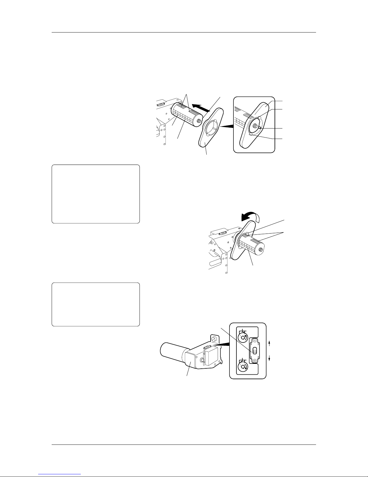
Supply Roll Holder
Claw
Tooth
Claw
Supply Shaft
Marks
Notches
Supply Roll Holder
CAUTION!
Do not push into the Supply
Roll Holder (inside) with the
claw locked in the notches, as
this may cause damage to the
claw or notches.
See Section 2.5.1 for more
detail.
8
Push the Supply Roll Holder (inside) to the end of the Supply
Shaft. Then turn the Supply Roll Holder counterclockwise so
that the claw is locked into the notch. When inserting the Supply
Roll Holder into the Supply Shaft, more pressure should be applied
when passing over the roller on the way to the end of the Supply
Shaft.
Claw
Notches
Marks
9
Switch the Back T ension Selector, depending on whether the media
is rolled outside or inside. Switch the Selector to A for the media
rolled outside. Switch it to B for the media rolled inside, as
indicated by the arrows.
Note:
The media is rolled either outside or
inside, depending on the type of media
that is loaded. Whichever media is
used, load it with print side facing up.
See Appendix 1 for more detail.
Supply Shaft Holder
Back Tension Selector
A
B
Media rolled outside
Media rolled inside
10
Measure width of the media that will be loaded.
Groove
2.5 Loading the
Media (Cont.)
Chapter 2 Printer Installation
13
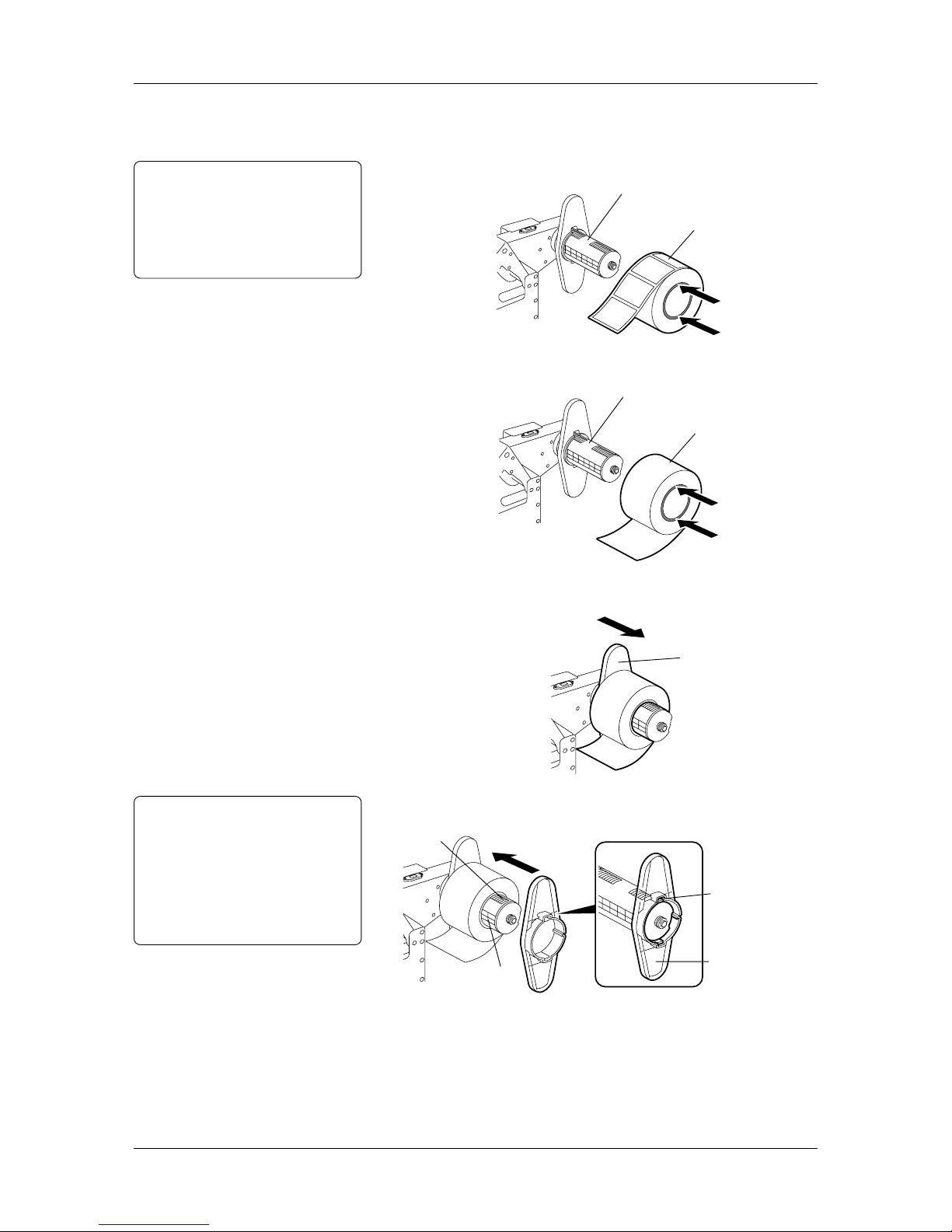
11
Based on width of the media measured in Step 10, push the media
into the Supply Roll Holder (inside), and place it with reference
to the marks on the Supply Shaft.
• Loading a roll of labels
Note:
When inserting a roll of labels or
tags, push on the media core only.
Otherwise, core material drags
against the Supply Shaft causing
telescoping of the media supply roll.
Supply Shaft
Labels
• Loading a roll of tags
Supply Shaft
Tags
12
Slide the Supply Roll Holder (inside) to the loaded media.
Supply Roll Holder
CAUTION!
To remove the Supply Roll
Holder (outside), turn it to
disengage the claw from the
notches. Otherwise, the claw or
the notches may be damaged.
See Section 2.5.1 for more
detail.
13
Slide the Supply Roll Holder (outside) to the loaded media.
Notches
Supply Shaft
Claw
Supply Roll Holder
(Outside)
2.5 Loading the
Media (Cont.)
Chapter 2 Printer Installation
14
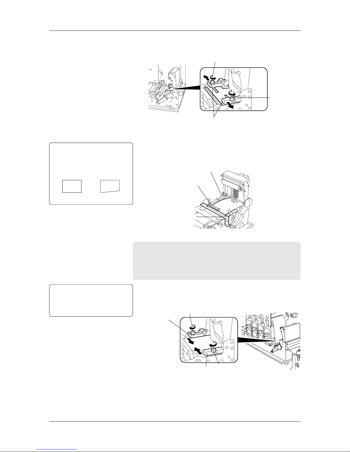
14
Loosen the two screws. Slide the Media Guides in the direction
of the arrows below until they stop (completely open).
Screw
Screw
Media Guides
15
Unroll about 1.5 to 2 inches (40 to 50cm) of the media.
16
Insert the media into the Media Inlet. Make sure that the media
passes under the Media End Sensor, the media sensor and the
Media Pressure Plate.
Media End Sensor
Media Sensor
Media Pressure Plate
Right Wrong
Note:
Make sure that the leading edge of
media is cut straight before inserting
the media into the printer , as this may
cause a media jam.
Important!
• According to the media is loaded, adjust the position of the
media sensor. See Section 2.6 for more detail.
• Whenever the type of media is changed, adjust sensitivity
of the media sensor. See Section 2.7 for more detail.
17
Slide the Media Guides in the direction of the arrows below until
both guides come in contact with the media (media should be in
center of media path). Hand tighten the two screws.
Screw
Screw
Media Guide
Media Guide
CAUTION!
Do not over tighten the two
screws, as this may cause
damage to the Media Guides.
2.5 Loading the
Media (Cont.)
Chapter 2 Printer Installation
15
18
Feed the media to the Media Outlet manually until its leading
edge comes out of the Media Outlet.
(Top View of the Printer)
Notes:
• Pass the media straight from the
Supply Holder Unit to the Media
Outlet to avoid skewing.
• Use the marks at the Media Slide
and the Media Outlet so that the
media can be centered.
• Be sure to take up any slack in the
media.
Media
Media Outlet Print Head Blocks
Media Guide
Media Inlet
Supply Roll
Holder
(Side View of the Printer)
Right
Wrong
Media
Media
Print Head Blocks
Pinch Roller
Print Head Blocks
Pinch Roller
19
Push down the Pinch Roller Unit until it is hooked. Then push
down the Pinch Roller Lever to the ROLLER LOCK position.
Note:
Push down the Pinch Roller Unit
gently on the “PUSH HERE” label.
[PUSH HERE]
Pinch Roller Lever
(To ROLLER LOCK)
20
Reinstall the Supply Shaft Holder Stand to the Supply Shaft Holder,
whose level is adjusted in Steps 3 to 5.
Supply Shaft Holder Stand
2.5 Loading the
Media (Cont.)

Chapter 2 Printer Installation
16
21
Close the Top Cover gently. Make sure that the POWER LED
and ON LINE LED are illuminated, and that the “ON LINE”
message is shown. Press the FEED key on the Operation Panel
to feed the media about 1 inch (20 to 30cm). Check that the media
is fed successfully.
Note:
When loading labels, make a straight
cut in the gap area between labels.
Right Wrong
Label
Cut here.
Label
This section contains more information concerning the care that should
be taken when loading the media.
• The figure below indicates the direction the Supply Roll Holder
(inside) can be moved with the claws of the Supply Roll Holder
locked into the notches.
2.5.1 Additional
Information
Right
Wrong
• The figure below indicates the direction the Supply Roll Holder
(outside) can be moved with the claws of the Supply Roll Holder
locked into the notches.
Right
Wrong
Notches
Supply Roll Holder
(Inside)
Supply Roll Holder
(Outside)
Notches
2.5 Loading the
Media (Cont.)
Chapter 2 Printer Installation
17
2.6 Sensor
Adjustments
This section describes in detail how to adjust the media sensor
positions and their sensitivity.
Whenever the type of media is changed, a positional adjustment of
the media sensor is needed. The media sensors are designed to keep
positional alignment of the image on each label or tag when issued.
Important!
NEVER skip the media sensor positional adjustment.
The printer has two types of media sensors: Black Mark Sensor and
Feed Gap Sensor.
The Black Mark Sensor (reflective sensor) is used to detect black
marks on the back of the media by the reflection of light. On the
other hand, the Feed Gap Sensor (transmissive sensor) is used to detect
gaps by the transmission of light.
Which media sensor to adjust depends on the type of media loaded.
When the media with black marks on the BACK is loaded, adjust the
Black Mark Sensor (reflective sensor) position as follows:
1
Open the Top Cover.
2
Lift the Pinch Roller Lever to the ROLLER RELEASE position
to open the Pinch Roller Unit.
3
Align the Media Guides to the width of the media.
4
Fold the media so that a black mark faces upward.
5
Insert the media into the Media Inlet.
6
Turn the Media Guide Knob, and move the media sensor so that it
is positioned at the center of the black mark.
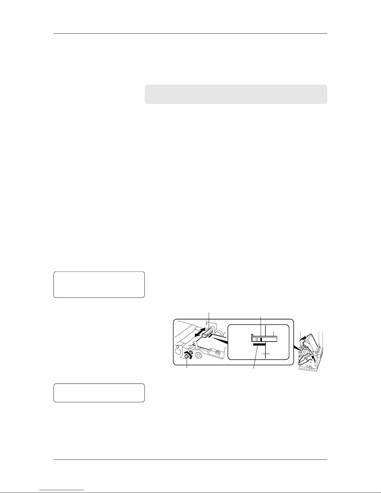
2.6.1 Black Mark
Sensor
Note:
“1” marked on the sensor indicates
the Black Mark Sensor position.
Media Sensor
Media Guide Knob
Black Mark detected here
Sensor
Media
Black Mark
7
The Black Mark Sensor Position Adjustment has been completed.
Note:
See A1.3.3 for black mark specifications.

Chapter 2 Printer Installation
18
2.6.2 Feed Gap Sensor When the media with gaps or rectangular holes is loaded, adjust the
Feed Gap Sensor (transmissive sensor) position as follows:
1
Open the Top Cover.
2
Lift the Pinch Roller Lever to the ROLLER RELEASE position
to open the Pinch Roller Unit.
3
Align the Media Guides to width of the media.
4
Insert the media into the Media Inlet.
• If the media with gaps is loaded, go to Step 5.
• If the media with rectangular holes is loaded, go to Step 6.
5
Turn the Media Guide Knob, and move the media sensor so that
the gap between labels will pass under the sensor.
Media Sensor
Media Guide Knob
Gap detected here
Sensor
Label
Gap
Backing Paper
Note:
“2” marked on the sensor indicates
the Feed Gap Sensor position.
6
Turn the Media Guide Knob, and move the media sensor so that it
is positioned at the center of the rectangular hole.
Media Sensor
Media Guide Knob
Hole detected here
Sensor
Hole
Media
7
The Feed Gap Sensor Position Adjustment has been completed.
Note:
See A1.3.2 for gap or hole specifications.
Chapter 2 Printer Installation
19
2.6.3 Media Sensor
Sensitivity
Adjustment
Whenever the type of media is changed, adjust the media sensor
sensitivity.
Please note that the adjustment procedures are slightly different,
depending on which type of media loaded.
Media Sensor Adjustor
Feed Gap Sensor Lamp
Black Mark Sensor Lamp
Green
Red
Black Mark Sensor
Adjusting Knob
Feed Gap Sensor Adjusting Knob
Black Mark Sensor Sensitivity Adjustment
1
Open the Top Cover.
2
Lift the Pinch Roller Lever to the ROLLER RELEASE position
to open the Pinch Roller Unit.
3
Insert the media with black marks into the Media Inlet so that the
Black Mark Sensor can detect the WHITE part of the media.
4
Lock the Pinch Roller Unit.
5
Turn on the printer.
6
Turn the Black Mark Sensor Adjusting Knob to the left most
position.
7
Keep turning the knob clockwise slowly. When the upper two
Black Mark Sensor Lamps illuminate green, the adjustment is
complete.
Note:
As soon as the upper two lamps
illuminate green, stop turning the knob.

Chapter 2 Printer Installation
20
Feed Gap Sensor Sensitivity Adjustment
(for Label with Gaps)
1
Open the Top Cover.
2
Lift the Pinch Roller Lever to the ROLLER RELEASE position
to open the Pinch Roller Unit.
3
Insert the label with gaps into the Media Inlet so that the Feed
Gap Sensor can detect the LABEL part.
4
Lock the Pinch Roller Unit.
5
Turn on the printer.
6
Turn the Feed Gap Sensor Adjusting Knob to the left most position.
7
Keep turning the knob clockwise slowly. When the upper two
Feed Gap Sensor Lamps illuminate green, the adjustment is
complete.
Feed Gap Sensor Sensitivity Adjustment
(for Media with Rectangular Holes)
1
Open the Top Cover.
2
Lift the Pinch Roller Lever to the ROLLER RELEASE position
to open the Pinch Roller Unit.
3
Insert the media with rectangular holes into the Media Inlet so
that the Feed Gap Sensor can detect the PAPER part.
4
Lock the Pinch Roller Unit.
5
Turn on the printer.
6
Turn the Feed Gap Sensor Adjusting Knob to the left most position.
7
Keep turning the knob clockwise slowly. When the upper two
Feed Gap Sensor Lamps illuminate green, the adjustment is
complete.
Note:
As soon as the upper two lamps
illuminate green, stop turning the knob.
Note:
As soon as the upper two lamps
illuminate green, stop turning the knob.
2.6.3 Media Sensor
Sensitivity
Adjustment (Cont.)
Chapter 2 Printer Installation
21
2.7 Loading the
Ribbons
(for Hot Release
Ribbons)
This section describes in detail how to load all four ribbons in the
printer.
Please use the ribbon width corresponding to the media width from
the table shown below.
Media Width
2 to 2.6 (50 to 65)
2.6 to 3.4 (65 to 85)
3.4 to 4.4 (85 to 110)
Ribbon Width
2.7 (68)
3.5 (88)
4.3 (109)
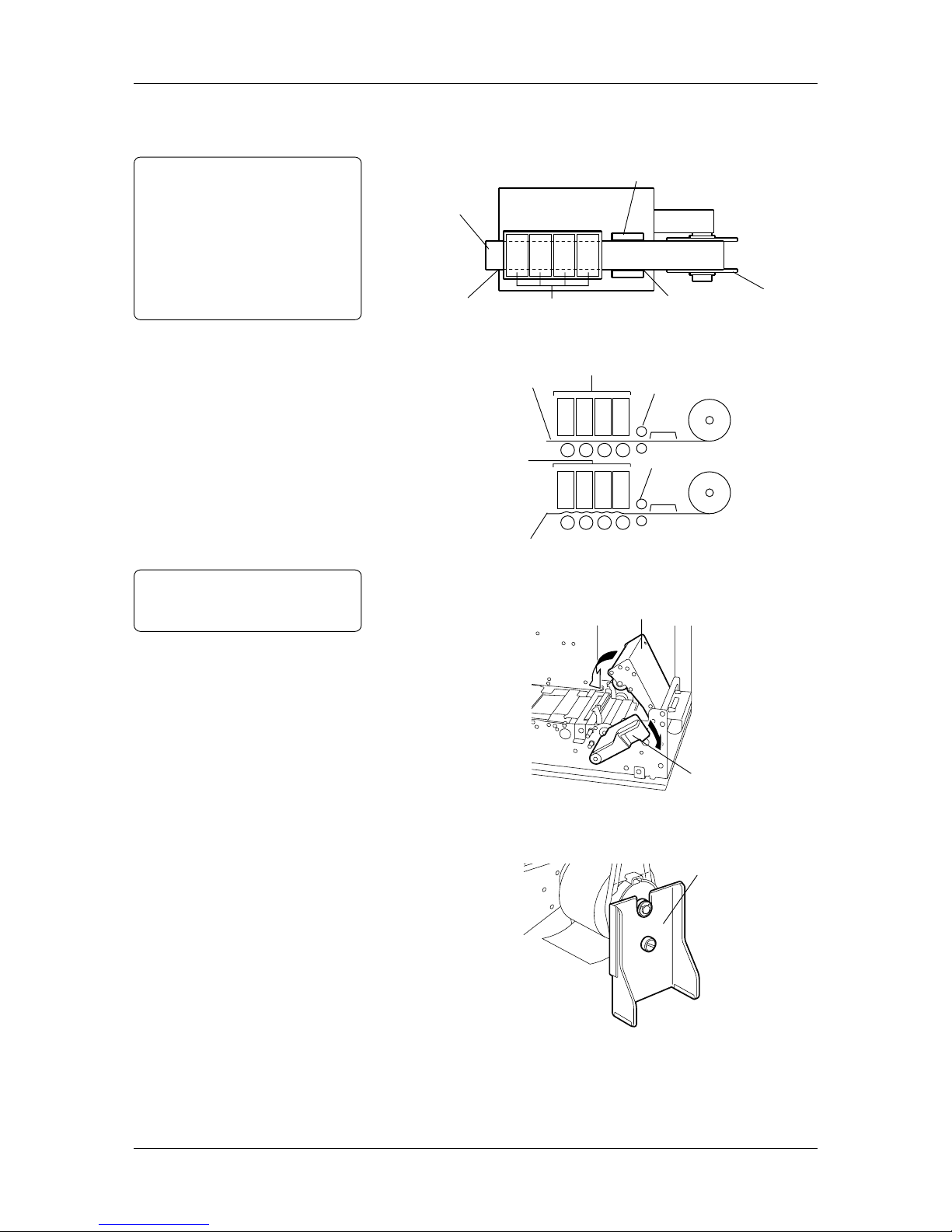
2.7.1 Ribbon Positions
Please load the four ribbons in the correct positions, as illustrated
below.
Note:
When using the spot color
ribbons, load them as specified in
the printer properties. See
Sections 3.4.5 and 3.4.6 for more
detail.
2.7.2 Loading
Procedure
1
Open the Top Cover.
2
Turn the Head Lever to the OPEN position. Pull out each Ribbon
Module in the direction of the arrow, and remove it from the printer .
Notes:
• Turn the Head Lever to the
OPEN position completely, or
the Ribbon Module cannot be
removed.
• Do not bend, drop, or give any
shock to the Ribbon Module.
Distortion of the Ribbon
Module may cause poor print.
3
Remove the two Ribbon Shafts from the Ribbon Module. Remove
the Ribbon Stopper from each Ribbon Shaft.
Ribbon Shaft
Ribbon Stoppers
Yellow (Y)
Cyan (C) Magenta (M)
Black (K)
HEAD
LOCK
OPEN
Head Lever
Ribbon Module
Note:
Media Width does not include width
of the backing paper.
Dimensions in inches + (mm)
There are two types of ribbons: high-performance Hot Release Ribbons
that provide fast, quality print, and the popular Cold Release Ribbons.
This section focuses on how to load the Hot Release Ribbons.
See Section 2.8 for loading procedures of the Cold Release Ribbons.
Also refer to the table in Section 3.8.1 for specific information about
each ribbon type. If the ribbon type to be used cannot be found in the
table, contact an authorized sales representative.
Chapter 2 Printer Installation
22
4
Insert the Ribbon Shaft into the Ribbon Winding Core. Fit the
protrusion of the Ribbon Shaft into the notch of the Ribbon
Winding Core. Insert the other Ribbon Shaft into the Ribbon Feed
Core in the same manner.
Protrusion
Notch
Ribbon Winding Core
Ribbon Shaft
Ribbon Feed Core
5
Attach the Ribbon Stoppers gently to each Ribbon Shaft.
CAUTION!
Push in the Ribbon Stoppers
gently. Otherwise, damage
may occur.
Ribbon Feed Core
Ribbon Shaft
Ribbon Stoppers
Ribbon Shaft
6
Unroll about 1 inch (30cm) of the ribbon. Place the Ribbon Module
on the ribbon.
Ribbon Module
Ribbon Winding Core
Ribbon
Ribbon Feed Core
CAUTION!
Loading the ribbon upside
down may cause damage to
the print head, as well as print
failure.
7
Insert the Ribbon Feed Core, and then the Ribbon Winding Core
on the Ribbon Module, as illustrated below.
Ribbon Winding Core
Ribbon Feed Core
Note:
Please make sure that the Ribbon
Stoppers are completely inserted into
the Ribbon Winding Cor e and Ribbon
Feed Core respectively.
Ribbon Winding Core
2.7.2 Loading
Procedure (Cont.)
 Loading...