

Toshiba TEC B-SX4T-QQ, TEC B-SX4T-QP Owner's Manual
TEC Thermal Printer
B-SX4T-QQ/QP
Owner's Manual
CE Compliance (for EU only)
This product complies with the requirements of EMC and Low Voltage Directives including their
amendments.
VORSICHT:
•
Schallemission: unter 70dB (A) nach DIN 45635 (oder ISO 7779)
•
Die für das Gerät Vorgesehene Steckdose muß in der Nähe des Gerätes und leicht zugänglich sein.
Copyright © 2003
by TOSHIBA TEC CORPORATION
All Rights Reserved
570 Ohito, Ohito-cho, Tagata-gun, Shizuoka-ken, JAPAN
Centronics is a registered trademark of Centronics Data Computer Corp.
Microsoft is a registered trademark of Microsoft Corporation.
Windows is a trademark of Microsoft Corporation.
As an ENERGY STAR® Partner, TOSHIBA TEC has determined that this
product meets the ENERGY STAR
®
guidelines for energy efficiency.
-- Outline of the International ENERGY STAR® Office Equipment Program --
The International ENERGY STAR
®
Office Equipment Program is an international program that
promotes energy saving through the penetration of energy efficient computers and other office
equipment. The program backs the development and dissemination of products with functions that
effectively reduce energy consumption. It is an open sy st em in which business proprietors can
participate voluntarily. The targeted products are office equipment such as computers, monitors,
printers, facsimiles, copiers, scanners, and multifunction devices. Their standards and logos are
uniform among participating nations.
E
NERGY STAR is a U.S. registered mark.
This equipment has been tested and found to comply with the limits for a Class A digital device,
pursuant to Part 15 of the FCC Rules. These limits are designed to provide reasonable rotection
against harmful interference when the equipment is operated in a commercial environment. This
equipment generates, uses, and can radiate radio frequency energy and, if not installed and sed in
accordance with the instruction manual, may cause harmful interference to radio communications.
Operations of this equipment in a residential area is likely to cause harmful interference in which case
the user will be required to correct the interference at his own expense.
(for USA only)
Changes or modifications not expressly approved by manufacturer for compliance could void the
user’s authority to operate the equipment.
“This Class A digital apparatus meets all requirements of the Canadian Interference-Causing
Equipment Regulations.”
“Cet appareil numérique de la classe A respecte toutes les exigences du Règlement sur le matériel
brouilleur du Canada.”
(for CANADA only)
Safety Summary
ENGLISH VERSION EO1-33034
( ) i
6DIHW\6XPPDU\
Personal safety in handling or maintaining the equipment is extremely important. Warnings and Cautions
necessary for safe handling are included in this manual. All warnings and cautions contained in this manual
should be read and understood before handling or maintaining the equipment.
Do not attempt to effect repairs or modifications to this equipment. If a fault occurs that cannot be rectified
using the procedures described in this manual, turn off the power, unplug the machine, then contact your
authorised TOSHIBA TEC representative for assistance.
0HDQLQJVRI(DFK6\PERO
This symbol indicates warning items (including cautions).
Specific warning contents are drawn inside the symbol.
(The symbol on the left indicates a general caution.)
This symbol indicates prohibited actions (prohibited items).
Specific prohibited contents are drawn inside or near the
symbol.
(The symbol on the left indicates “no disassembling”.)
This symbol indicates actions which must be performed.
Specific instructions are drawn inside or near the ● symbol.
(The symbol on the left indicates “disconnect the power cord plug from the outlet”.)
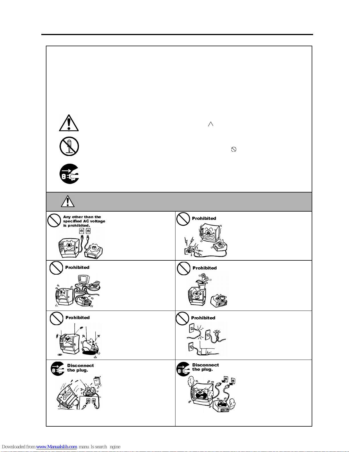
This indicates that there is the risk of death or serious injury if the
machines are improperly handled contrary to this indication.
Do not use voltages other than
the voltage (AC) specified on the
rating plate, as this may cause
fire
or
electric shock
.
Do not plug in or unplug the power
cord plug with wet hands as this
may cause
electric shock
.
If the machines share the same
outlet with any other electrical
appliances that consume large
amounts of power, the voltage
will fluctuate widely each time
these appliances operate. Be sure
to provide an exclusive outlet for
the machine as this may cause
fire
or
electric shock
.
Do not place metal objects or
water-filled containers such as
flower vases, flower pots or mugs,
etc. on top of the machin es. If
metal objects or spilled liquid enter
the machines, this may cause
fire
or
electric shock
.
Do not insert or drop metal,
flammable or other foreign
objects into the machines through
the ventilation slits, as this may
cause
fire
or
electric shock
.
Do not scratch, damage or modify
the power cords. Also, do not
place heavy objects on, pull on, or
excessively bend the cords, as this
may cause
fire
or
electrical shock.
If the machines are dropped or
their cabinets damaged, first turn
off the power switches and
disconnect the power cord plugs
from the outlet, and then contact
your authorised TOSHIBA TEC
representative for assistance.
Continued use of the machine in
that condition may cause
fire
or
electric shock
.
Continued use of the machines in
an abnormal condition such as
when the machines are producing
smoke or strange smells may cause
fire
or
electric shock
. In these
cases, immediately turn off the
power switches and disconnect the
power cord plugs from the outlet.
Then, contact your authorised
TOSHIBA TEC representative for
assistance.
:$51,1*
$Q\ RWKHU WKDQ WKH
VSHFLILHG $& YROWDJH
LV SURKLELWHG
3URKLELWHG
3URKLELWHG
3URKLELWHG
3URKLELWHG
3URKLELWHG
'LVFRQQHFW
WKH SOXJ
'LVFRQQHFW
WKH SOXJ
Safety Summary
ENGLISH VERSION EO1-33034
( ) ii
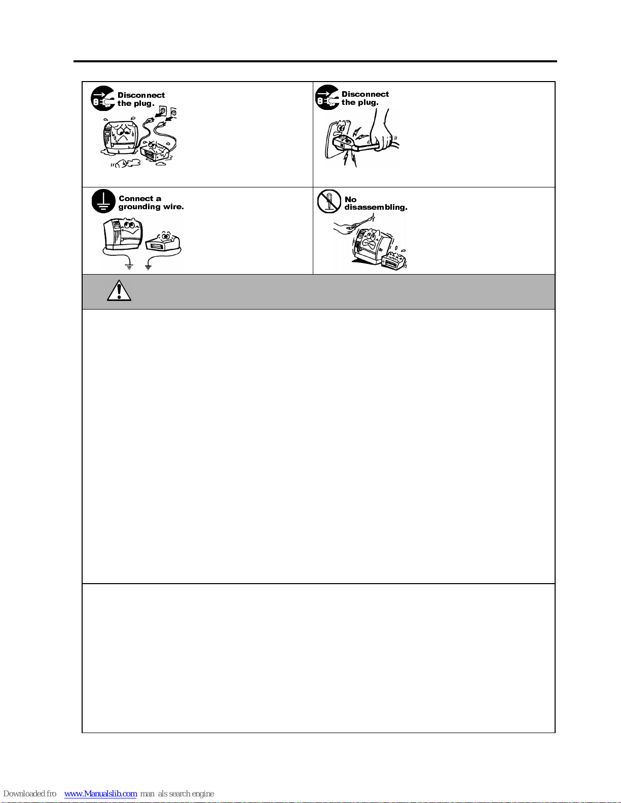
If foreign objects (metal
fragments, water, liquids) enter
the machines, first turn off the
power switches and disconnect
the power cord plugs from the
outlet, and then contact your
authorised TOSHIBA TEC
representative for assistance.
Continued use of the machine in
that condition may cause
fire
or
electric shock
.
When unplugging the power cords,
be sure to hold and pull on the plug
portion. Pulling on the cord portion
may cut or expose the internal wires
and cause
fire
or
electric shock
.
Ensure that the equipment is
properly grounded. Extension
cables should also be grounded.
Fire
or
electric shock
could
occur on improperly grounded
equipment.
Do not remove covers, repair or
modify the machine by yourself.
You may be
injured
by high
voltage, very hot parts or sharp
edges inside the machine.
This indicates that there is the risk of personal
Injury
or
damage
to
objects if the machines are improperly handled contrary to this indication.
Precautions
The following precautions will help to ensure that this machine will continue to function correctly.
●
Try to avoid locations that have the following adverse conditions:
* Temperatures out of the specification * Direct sunlight * High humidity
* Shared power source * Excessive vibration * Dust/Gas
●
The cover should be cleaned by wiping with a dry cloth or a cloth slightly dampened with a mild
detergent solution. NEVER USE THINNER OR ANY OTHER VOLATILE SOLVENT on the plastic
covers.
●
USE ONLY TOSHIBA TEC SPECIFIED paper and ribbons.
●
DO NOT STORE the paper or ribbons where they might be exposed to direct sunlight, high
temperatures, high humidity, dust, or gas.
●
Ensure the printer is operated on a level surface.
●
Any data stored in the memory of the printer could be lost during a printer fault.
●
Try to avoid using this equipment on the same power supply as high voltage equipment or equipment
likely to cause mains interference.
●
Unplug the machine whenever you are working inside it or cleaning it.
●
Keep your work environment static free.
●
Do not place heavy objects on top of the machines, as these items may become unbalanced and fall
causing injury.
●
Do not block the ventilation slits of the machines, as this will cause heat to build up inside the
machines and may cause fire.
●
Do not lean against the machine. It may fall on you and could cause injury.
●
Care must be taken not to injure yourself with the printer paper cutter.
●
Unplug the machine when it is not used for a long period of time.
●
Place the machine on a stable and level surface.
Request Regarding Maintenance
●
Utilize our maintenance services.
After purchasing the machine, contact your authorised TOSHIBA TEC representative for assistance
once a year to have the inside of the machine cleaned. Otherwise, dust will build up inside the
machines and may cause a fire or a malfunction. Cleaning is particularly effective before humid rainy
seasons.
●
Our preventive maintenance service performs the periodic checks and other work required to maintain
the quality and performance of the machines, preventing accidents beforehand.
For details, please consult your authorised TOSHIBA TEC representative for assistance.
●
Using insecticides and other chemicals
Do not expose the machines to insecticides or other volatile solvents. This will cause the cabinet or
other parts to deteriorate or cause the paint to peel.
&$87,21
'LVFRQQHFW
WKH SOXJ
&RQQHFW D
JURXQGLQJ ZLUH
'LVFRQQHFW
WKH SOXJ
1R
GLVDVVHPEOLQJ

ENGLISH VERSION EO1-33034
TABLE OF CONTENTS
Page
1. PRODUCT OVERVIEW.......................................................................................................... E1-1
1.1 Introduction....................................................................................................................E1-1
1.2 Features.........................................................................................................................E1-1
1.3 Unpacking......................................................................................................................E1-1
1.4 Accessories ..................................................................................................................E1-2
1.5 Appearance ................................................................................................................... E1-3
1.5.1 Dimensions................................................................................................................E1-3
1.5.2 Front View.................................................................................................................. E1-3
1.5.3 Rear View ..................................................................................................................E1-3
1.5.4 Operation Panel......................................................................................................... E1-4
1.5.5 Interior........................................................................................................................ E1-4
2. PRINTER SETUP ...................................................................................................................E2-1
2.1 Precautions....................................................................................................................E2-1
2.2 Procedure before Operation .......................................................................................... E2-2
2.3 Fitting the Fan Filter.......................................................................................................E2-2
2.4 Connecting the Cables to Your Printer .......................................................................... E2-3
2.5 Connecting the Power Cord...........................................................................................E2-4
2.6 Turning the Printer ON/OFF........................................................................................... E2-5
2.6.1 Turning ON the Printer............................................................................................... E 2-5
2.6.2 Turning OFF the Printer............................................................................................. E2-5
2.7 Loading the Media .........................................................................................................E2-6
2.8 Loading the Ribbon...................................................................................................... E2-11
2.9 Inserting the Optional PCMCIA Cards .........................................................................E2-12
2.10 Test Print ..................................................................................................................... E2-13
3. ON LINE MODE......................................................................................................................E3-1
3.1 Operation Panel.............................................................................................................E3-1
3.2 Operation.......................................................................................................................E3-2
3.3 Reset .............................................................................................................................E3-2
3.4 Dump Mode ...................................................................................................................E3-3
4. MAINTENANCE......................................................................................................................E4-1
4.1 Cleaning.........................................................................................................................E4-1
4.1.1 Print Head/Platen/Sensors......................................................................................... E4-1
4.1.2 Covers and Panels.....................................................................................................E4-2
4.1.3 Optional Cutter Module.............................................................................................. E4-2
4.2 Care/Handling of the Media and Ribbon........................................................................ E4-3
5. TROUBLESHOOTING............................................................................................................ E5-1
5.1 Error Messages .............................................................................................................E5-1
5.2 Possible Problems.........................................................................................................E5-2
5.3 Removing Jammed Media............................................................................................. E5-3
5.4 Threshold Setting...........................................................................................................E5-4

ENGLISH VERSION EO1-33034
APPENDIX 1 SPECIFICATIONS.................................................................................................EA1-1
A1.1 Printer ..........................................................................................................................EA1-1
A1.2 Options ........................................................................................................................EA1-2
A1.3 Media...........................................................................................................................EA1-2
A1.3.1 Media Type.......................................................................................................EA1-2
A1.3.2 Detection Area of the Transmissive Sensor.....................................................EA1-3
A1.3.3 Detection Area of the Reflective Sensor...........................................................EA1-4
A1.3.4 Effective Print Area...........................................................................................EA1-4
A1.4 Ribbon .........................................................................................................................EA1-5
APPENDIX 2 MESSAGES AND LEDS.......................................................................................EA2-1
APPENDIX 3 INTERFACE..........................................................................................................EA3-1
APPENDIX 4 PRINT SAMPLES..................................................................................................EA4-1
GLOSSARIES
INDEX
CAUTION!
1. This manual may not be copied in whole or in part without prior written permission of TOSHIBA TEC.
2. The contents of this manual may be changed without notification.
3. Please refer to your local Authorised Service representative with regard to any queries you may have in
this manual.
This is a Class A product. In a domestic environment this product may cause radio interference in
which case the user ma
y
be required to take adequate measures.
WARNING!

1. PRODUCT OVERVIEW
ENGLISH VERSION EO1-33034
1.1 Introduction
E1- 1
1. PRODUCT OVERVIEW
1.1 Introduction
1.2 Features
1.3 Unpacking
Thank you for choosing the TEC B-SX4T series thermal printer. This
Owner’s Manual contains from general set-up through how to confirm
the printer operation using a test print, and should be read carefully to
help gain maximum performance and life from your printer. For most
queries please refer to this manual and keep it safe for future reference.
Please contact your TOSHIBA TEC representative for further
information concerning this manual.
This printer has the following features:
• The print head block can be opened providing smooth loading of
media and ribbon.
• Various kinds of media can be used as the media sensors can be
moved from the centre to the left edge of the media.
• When the optional interface board is installed, Web functions such as
remote maintenance and other advanced network features are
available.
• Superior hardware, including the specially developed 8 dots/mm (203
dots/inch) thermal print head which will allow very clear print at a
printing speed of 76.2 mm/sec. (3 inches/sec.), 152.4 mm/sec. (6
inches/sec.), or 254.0 mm/sec. (10 inches/sec.).
• Besides the optional Cutter Module, there is also an optional Strip
Module, Ribbon Saving Module, PCMCIA Interface Board,
Expansion I/O Interface Board, LAN Interface Board, and the USB
Interface Board.
Unpack the printer as per the Unpacking Instructions supplied with the
printer.
NOTES:
1. Check for damage or
scratches on the printer.
However, please note that
TOSHIBA TEC shall have no
liability for any damage of
any kind sustained during
transportation of the product.
2. Keep the cartons and pads
for future transportation of
the printer.
1. PRODUCT OVERVIEW
ENGLISH VERSION EO1-33034
1.4 Accessories
E1- 2
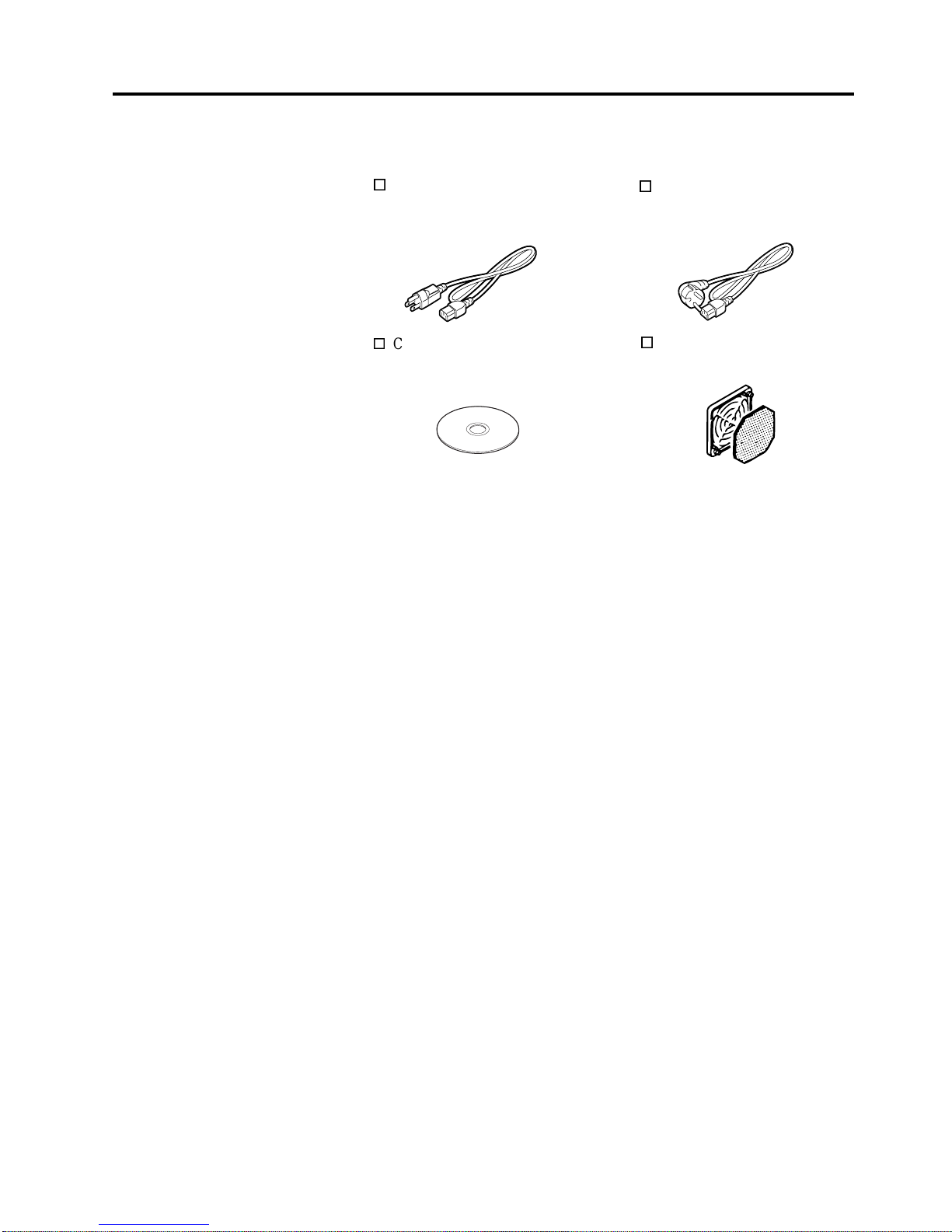
1.4 Accessories
When unpacking the printer, please make sure all the following
accessories are supplied with the printer.
US Power Cord (1 pc.)
(P/No. FBCB0030203)
QQ model only
CD-ROM (1 pc.)
QQ (P/No.: 7FM00331000)
QP (P/No.: 7FM00254000)
EU Power Cord (1 pc.)
(P/No.EKA-0030001)
QP model only
Fan Filter (1 pc.)
(P/No. FMBB0036801)
1. PRODUCT OVERVIEW
ENGLISH VERSION EO1-33034
1.5 Appearance
E1- 3
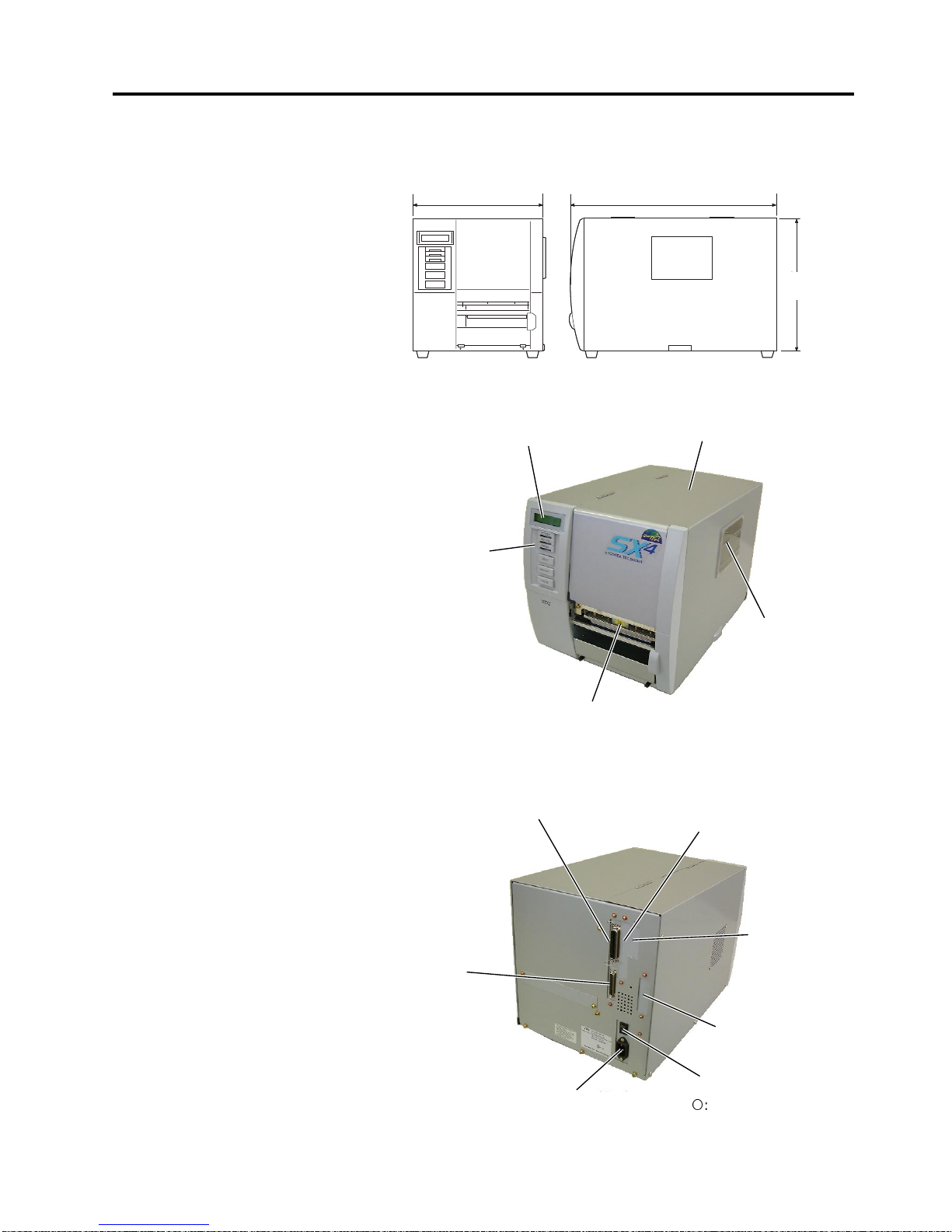
1.5 Appearance
1.5.1 Dimensions
1.5.2 Front View
1.5.3 Rear View
The names of the parts or units introduced in this section are used in the
following chapters.
Dimensions in mm (inches)
LCD Message Display
Operation Panel
Power Switch
{
: OFF
|: ON
Media Outlet
Top Cover
Expansion I/O
Interface Connector
(Option)
Serial Interface
Connector (RS-232C)
Parallel Interface
Connector (Centronics)
Supply Window
PCMCIA Card Slot (Option),
USB Connector (Option), or
LAN Connector (Option)
AC Power Inlet
291 460
308
308
(12.1)
291 (11.5)
460 (18.1)
USB Connector
(Option) or LAN
Connector (Option)
1. PRODUCT OVERVIEW
ENGLISH VERSION EO1-33034
1.5 Appearance
E1- 4
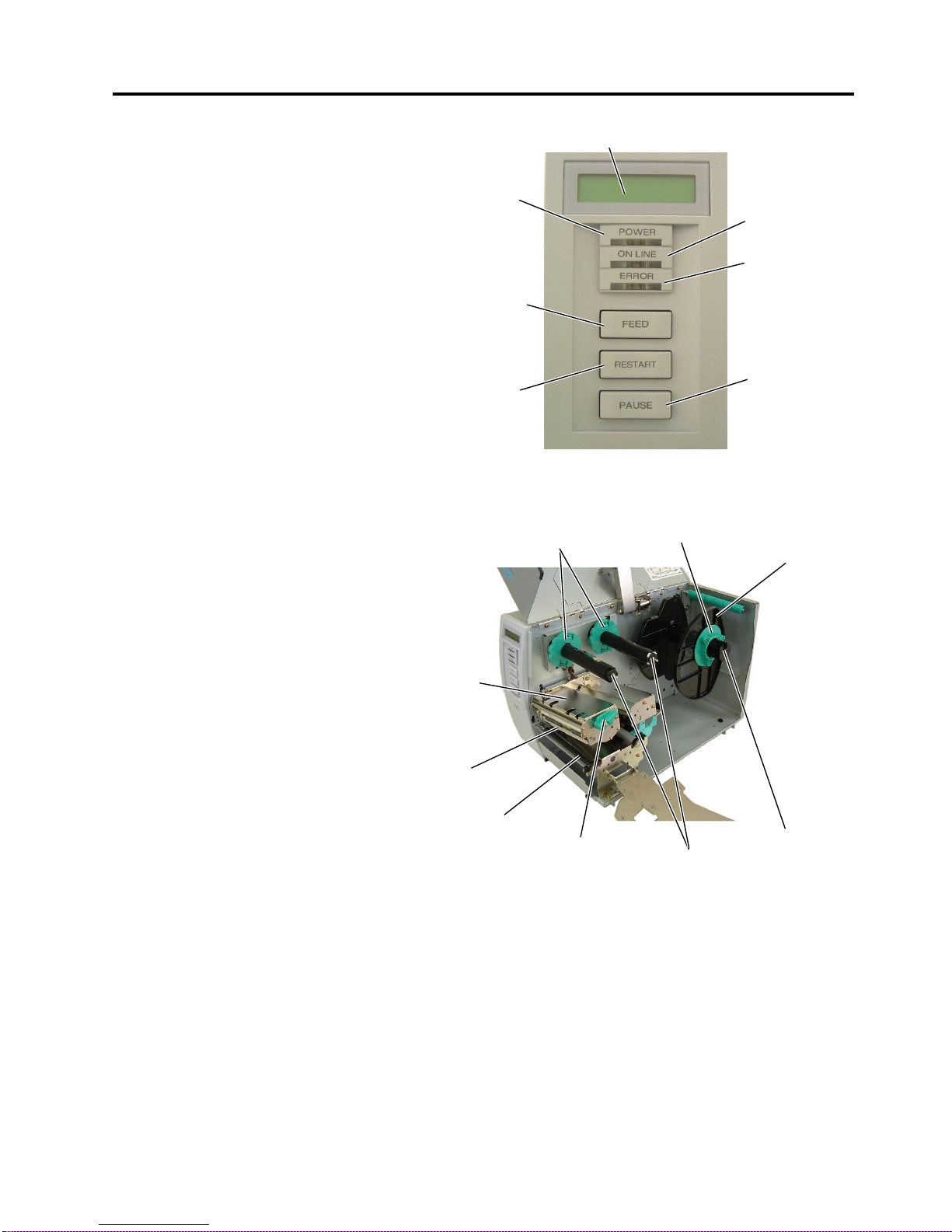
1.5.4 Operation Panel
1.5.5 Interior
Please see Section 3.1 for further information about the Operation Panel.
LCD Message Display
ON LINE LED
(Green)
ERROR LED
(Red)
[PAUSE]
key
POWER LED
(Green)
[FEED]
ke
y
[RESTART]
ke
y
Ribbon Stoppe
r
Print Head Block
Head Lever
Ribbon Shaft
Supply Holder
Locking Ring
Supply Shaft
Print Head
Platen

2. PRINTER SETUP
ENGLISH VERSION EO1-33034
2.1 Precautions
E2- 1
2. PRINTER SETUP
2.1 Precautions
This section outlines the procedures to setup your printer prior to its
operation. The section includes precautions, connecting cables,
assembling accessories, loading media and ribbon, inserting the optional
memory card, and performing a test print.
To insure the best operating environment, and to assure the safety of the
operator and the equipment, please observe the following precautions.
• Operate the printer on a stable, level, operating surface in a location
free from excessive humidity, high temperature, dust, vibration or
direct sunlight.
• Keep your work environment static free. Static discharge can cause
damage to delicate internal components.
• Make sure that the printer is connected to a clean source of AC
Power and that no other high voltage devices that may cause line
noise interference are connected to the same mains.
• Assure that the printer is connected to the AC mains with a three-
prong power cable that has the proper ground (earth) connection.
• Do not operate the printer with the cover open. Be careful not to
allow fingers or articles of clothing to get caught into any of the
moving parts of the printer especially the optional cutter mechanism.
• Make sure to turn off the printer power and to remove the power cord
from the printer whenever working on the inside of the printer such
as changing the ribbon or loading the media, or when cleaning the
printer.
• For best results, and longer printer life, use only TOSHIBA TEC
recommended media and ribbons.
• Store the media and ribbons in accordance with their specifications.
• This printer mechanism contains high voltage components; therefore
you should never remove any of the covers of the machine as you
may receive an electrical shock. Additionally, the printer contains
many delicate components that may be damaged if accessed by
unauthorised personnel.
• Clean the outside of the printer with a clean dry cloth or a clean cloth
slightly dampened with a mild detergent solution.
• Use caution when cleaning the thermal print head as it may become
very hot while printing. Wait until it has had time to cool before
cleaning. Use only the TOSHIBA TEC recommended print head
cleaner to clean the print head.
• Do not turn off the printer power or remove the power plug while the
printer is printing or while the ON LINE lamp is blinking.
2. PRINTER SETUP
ENGLISH VERSION EO1-33034
2.2 Procedure before Operation
E2- 2
2.2 Procedure before
Operation
2.3 Fitting the Fan Filter
This section describes the outline of the printer setup.
1.
Unpack the accessories and printer from the box.
2.
Refer to Safety Precautions in this manual and set up the printer at a
proper location.
3.
Fit the Fan Filter to the printer. (Refer to Section 2.3.)
4.
The host computer must have a serial, Centronics parallel, USB or
LAN port. (Refer to Section 2.4.)
5.
Be sure to insert the power cord plug into an AC outlet. (Refer to
Section 2.5.)
6.
Load the media. (Refer to Section 2.7.)
7.
Adjust the position of the Feed Gap Sensor or Black Mark Sensor
depending on the media being used. (Refer to Section 2.7.)
8.
Load the ribbon. (Refer to Section 2.8.)
9.
Turn the power ON. (Refer to Section 2.6.)
10.
Perform a test print. (Refer to Section 2.10.)
11.
Install the Printer Drivers. (Refer to the Printer Driver Manual.)
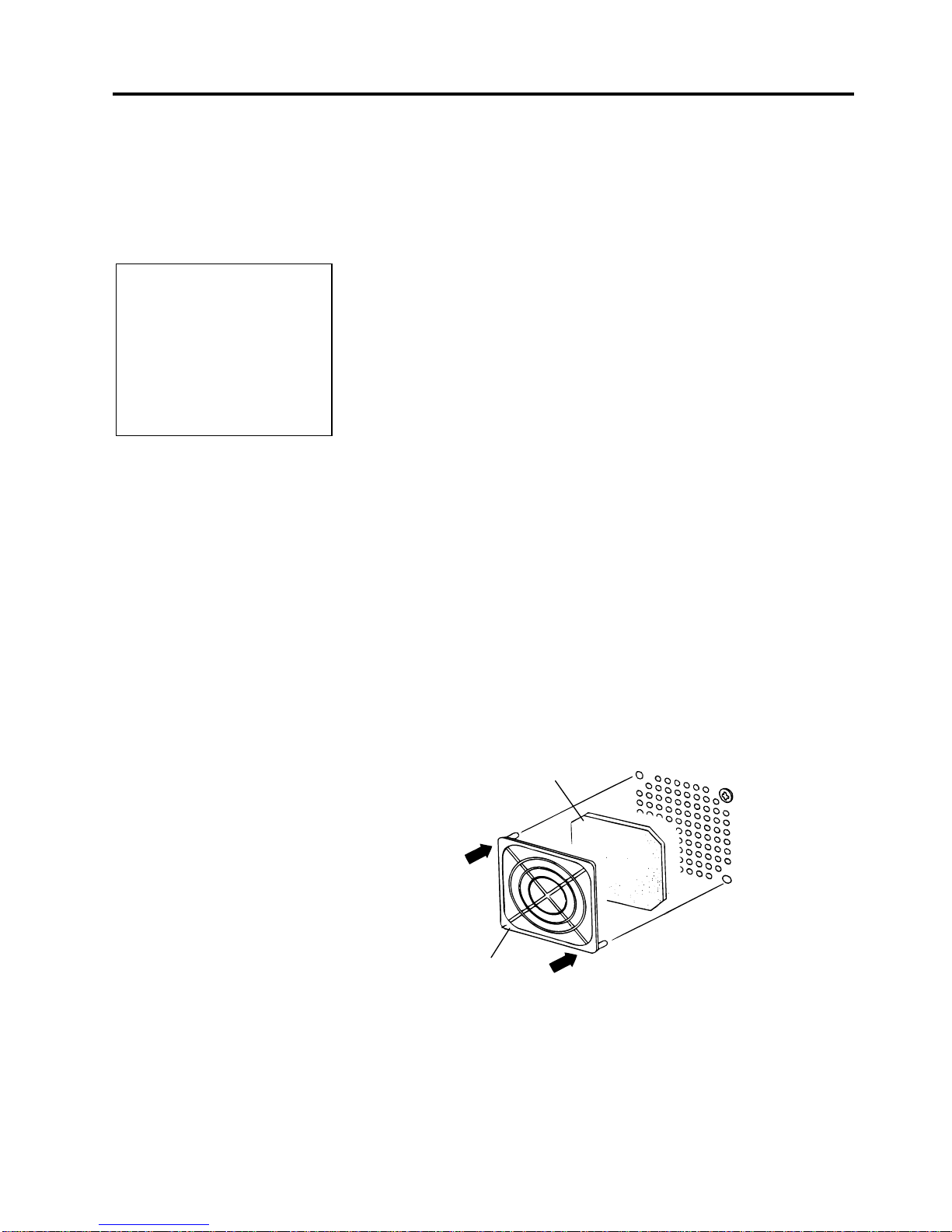
When installing the printer, it is important to ensure that the Fan Filter is
attached before using the printer.
The Fan Filter consists of 2 parts:
(1) Filter Pad
(2) Filter Retainer
To fit the Fan Filter, put the Filter Pad inside the Filter Retainer and
simply press into place as shown in the diagram below, ensuring
connecting pins are aligned with the connecting holes.
NOTE:
To communicate with the host
computer, one of the following
cables is required.
(1) RS-232C cable: 25 pins
(2) Centronics cable: 36 pins
(3) USB: B plug (Option)
(4) LAN: 10 Base-T or 100
Base-TX (Option)
Filter Pad
Filter Retainer
Snap On
Snap On
2. PRINTER SETUP
ENGLISH VERSION EO1-33034
2.4 Connecting the Cables to Your Printer
E2- 3
2.4 Connecting the
Cables to Your
Printer
The following paragraphs outline how to connect the cables from the
printer to your host computer, and will also show how to make cable
connections to other devices. Depending on the application software
you use to print labels, there are 4 possibilities for connecting the
printer to your host computer. These are:
• A serial cable connection between the printer’s RS-232 serial
connector and one of your host computer’s COM ports.
(Refer to APPENDIX 3.)
• A parallel cable connection between the printer’s standard parallel
connector and your host computer’s parallel port (LPT).
• An Ethernet connection using the optional LAN board.
• A USB cable connection between the printer’s optional USB
connector and your host computer’s USB port. (Conforming to
USB 1.1)
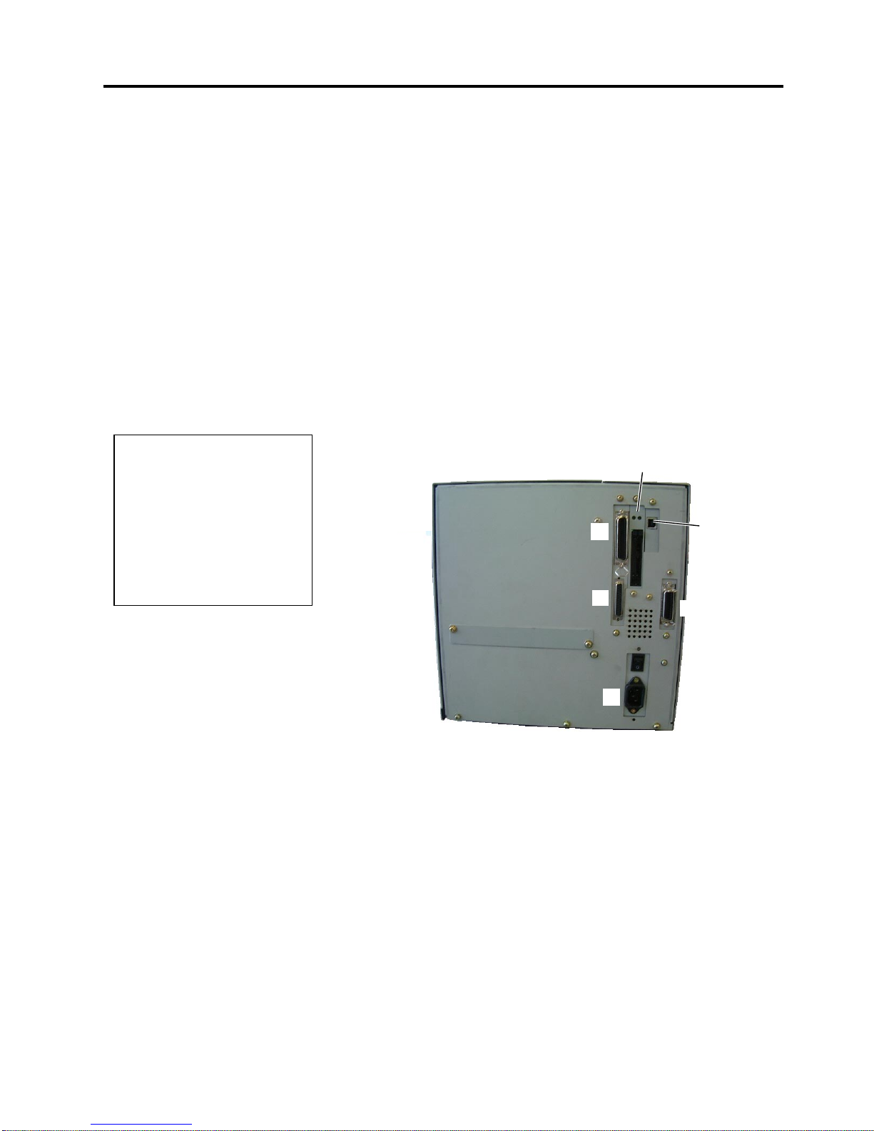
The diagram below shows all the possible cable connections to the
current version of the printer.
c Parallel Interface Connector (Centronics)
d Serial Interface Connector (RS-232C)
e Expansion I/O Interface Connector (Option)
f Power Inlet
g USB Interface Connector (Option)
h PCMCIA Card Slot (Option)
i LAN Interface Connector (Option)
c
d
e
f
g, h
,
or
i
NOTES:
1. The picture on the right shows
the layout of the interface
connectors when the options
are fully installed. It may be
different depending on your
system configuration.
2. The USB interface and LAN
interface cannot be used at the
same time.
gori
2. PRINTER SETUP
ENGLISH VERSION EO1-33034
2.5 Connecting the Power Cord
E2- 4
2.5 Connecting the
Power Cord
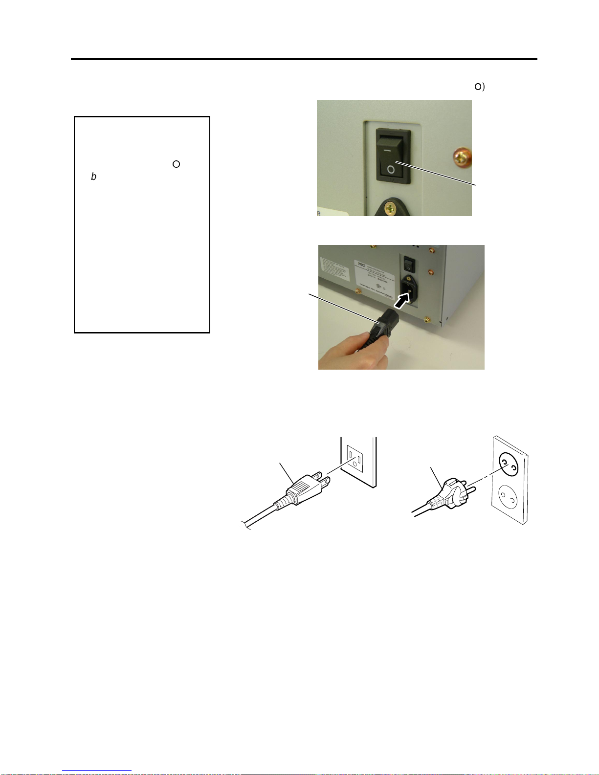
1.
Make sure that the printer Power Switch is in the OFF (
{
{
) position.
2.
Connect the Power Cord to the printer as shown in the figure below.
3.
Plug the other end of the Power Cord into a grounded outlet as shown
in the figure below.
[QQ Type] [QP Type]
CAUTION!
1. Make sure that the pr int e
r
Power Switch is turned to
the OFF position (
{
)
before connecting the
Power Cord to prevent
possible electric shock or
damage to the printer.
2. Use only the Power Cord
supplied with the printer.
Use of any other cord
may cause electric shock
or fire.
3. Connect the Power Cor d
to a supply outlet with a
properly grounded
(earthed) connection.
Power Cord
Power Cord
Power Cord
Power Switch
2. PRINTER SETUP
ENGLISH VERSION EO1-33034
2.6 Turning the Printer ON/OFF
E2- 5
2.6 Turning the Printer
ON/OFF
2.6.1 Turning ON the Printer
2.6.2 Turning OFF the Printer
When the printer is connected to your host computer it is good practice to
turn the printer ON before turning on your host computer and turn OFF
your host computer before turning off the printer.
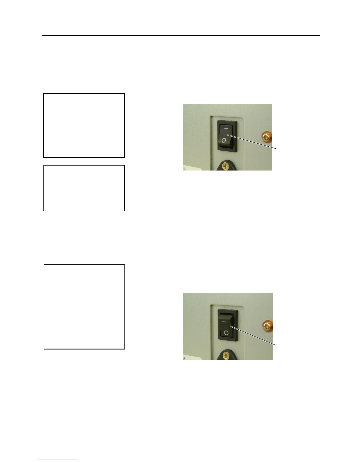
1.
To turn ON the printer power, press the Power Switch as shown in the
diagram below. Note that (
|
)
is the power ON side of the switch.
2.
Check that the ON LINE message appears in the LCD Message
Display and that the ON LINE and POWER LED lights are
illuminated.
1.
Before turning off the printer Power Switch verify that the ON LINE
message appears in the LCD Message Display and that the ON LINE
LED light is on and is not flashing.
2.
To turn OFF the printer power press the Power Switch as shown in the
diagram below. Note that ({)
is the power OFF side of the switch.
CAUTION!
Use the power switch to turn
the printer On/Off. Plugging
or unplugging the Power
Cord to turn the printer
On/Off may cause fire, an
electric shock, or damage to
the printer.
CAUTION!
1. Do not turn off the printer
power while the media is
being printed as this may
cause a paper jam or
damage to the printer.
2. Do not turn off the printer
power while the ON LINE
lamp is blinking as this
may cause damage to
your computer.
Power Switch
Power Switch
NOTE:
I
f a message other than ON
L
INE appears on the display or
the ERROR LED lamp is
illuminated, go to Section 5.1,
Error Messages.
2. PRINTER SETUP
ENGLISH VERSION EO1-33034
2.7 Loading the Media
E2- 6
2.7 Loading the Media
The following procedure shows the steps to properly load the media into
the printer so that it feeds straight and true through the printer.
The printer prints both labels and tags.
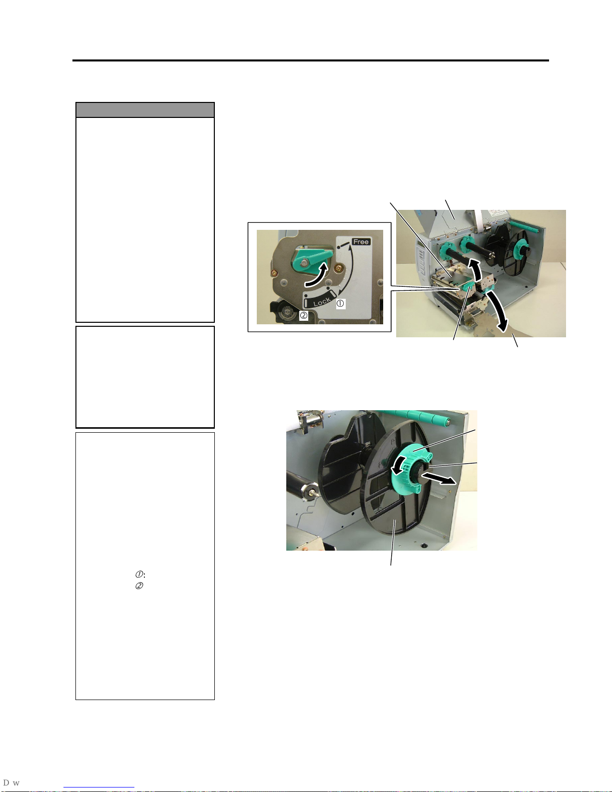
1.
Turn off the power and open the Top Cover.
2.
Turn the Head Lever to
Free
position, then release the Ribbon Shaft
Holder Plate.
3.
Open the Print Head Block.
4.
Turn the Locking Ring counterclockwise and remove the Supply
Holder from the Supply Shaft.
1. Do not touch any moving
parts. To reduce the risk
of fingers, jewellery,
clothing, etc., being
drawn into the moving
parts, be sure to load the
media once the printer
has stopped moving
completely.
2. The Print Head becomes
hot immediately after
printing. Allow it to cool
before loading the media.
3. To avoid injury, be caref ul
not to trap your fingers
while opening or closing
the cover.
WARNING!
NOTES:
1. When the Head Lever is
turned to
Free
position, the
Print Head is raised.
2. To allow printing the Head
Lever must be set to
Lock
position. (This ensures that
the Print Head is closed.)
There are two head pressure
levels in the
Lock
position.
Set the Head Lever depending
on the media type:
Position c: Labels
Position d: Tags
However, proper position
may differ depending on
media. For details, refer to
TOSHIBA TEC authorised
service representative.
3. Do not turn the Locking Ring
counter-clockwise too far or it
may come off the Supply
Holder.
CAUTION!
Be careful not to touch the
Print Head Element when
raising the Print Head Block.
Failure to do this may cause
missing dots by static
electricity or other print
q
uality problems.
Top Cover
Head Lever
Print Head Block
Locking Ring
Supply Holder
Supply Shaft
Ribbon Shaft
Holder Plate
c
d
2. PRINTER SETUP
ENGLISH VERSION EO1-33034
2.7 Loading the Media
E2- 7
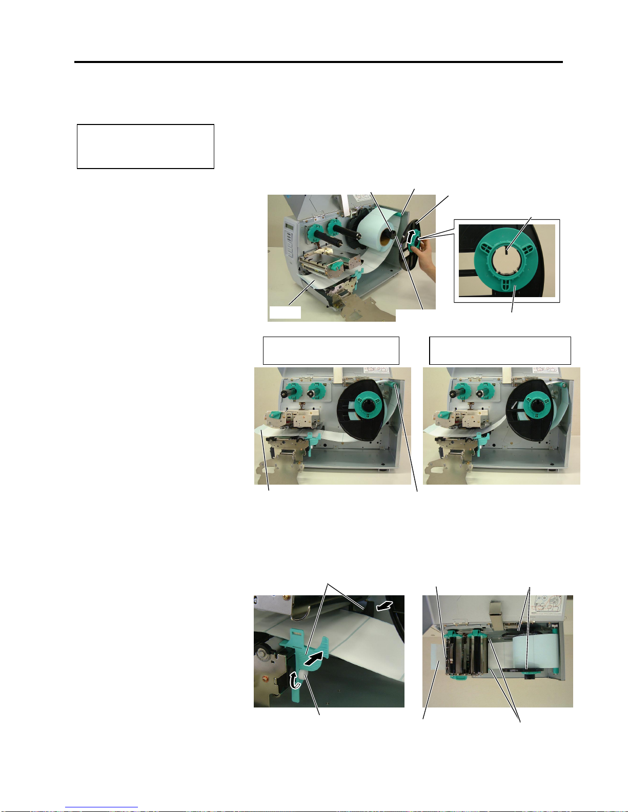
2.7 Loading the Media
(Cont.)
5.
Put the media on the Supply Shaft.
6.
Pass the media around the Damper, then pull the media towards the
front of the printer.
7.
Align the projection of the Supply Holder with the groove of the
Supply Shaft, and push the Supply Holder against the media until the
media is held firmly in place. This will center the media
automatically.
Then turn the Locking Ring clockwise to secure the Supply Holder.
8.
Place the media between the Media Guides, adjust the Media Guides
to the media width, and tighten the Locking Screw.
9.
Check that the media path through the printer is straight. The media
should be centered under the Print Head.
NOTE:
D
o not over-tighten the Locking
R
ing of the Supply Holder.
Supply Shaft
Suppl
y
Holder
Groove
Damper
Locking Ring
Projection
Media
Media Guide
Supply Holder
Media Guide
Print Head
Locking Screw
Media
Damper
Media
In case of a label rolled with
the print side facing inside.
In case of a label rolled with
the print side facing outside.
 Loading...