

Toshiba TEC B-852-TS12-QQ Owner's Manual
TEC Label/Tag Printer
B-852-TS12-QQ
Owner's Manual
This equipment has been tested and found to comply with the limits for a Class A digital device,
pursuant to Part 15 of the FCC Rules. These limits are designed to provide reasonable protection
against harmful interference when the equipment is operated in a commercial environment. This
equipment generates, uses, and can radiate radio frequency energy and, if not installed and used in
accordance with the instruction manual, may cause harmful interference to radio communications.
Operations of this equipment in a residential area is likely to cause harmful interference in which
case the user will be required to correct the interference at his own expense.
(for USA only)
Changes or modifications not expressly approved by manufacturer for compliance could void the
user’s authority to operate the equipment.
“This Class A digital apparatus meets all requirements of the Canadian Interference-Causing
Equipment Regulations.”
“Cet appareil numérique de la classe A respecte toutes les exigences du Règlement sur le matériel
brouilleur du Canada.”
(for CANADA only)
Copyright © 2002
by TOSHIBA TEC CORPORATION
All Rights Reserved
570 Ohito, Ohito-cho, Tagata-gun, Shizuoka-ken, JAPAN
HP-PCL5 is a registered trademark of Hewlett Packard Corporation.
Centronics is a registered trademark of Centronics Data Computer Corp.
Microsoft is a registered trademark of Microsoft Corporation.
Windows is a trademark of Microsoft Corporation.
As an ENERGY STAR® Partner, TOSHIBA TEC has determined that this
product meets the
E
NERGY STAR® guidelines for energy efficiency.
-- Outline of the International ENERGY STAR® Office Equipment Program --
The International
E
NERGY STAR® Office Equipment Program is an international program that
promotes energy saving through the penetration of energy efficient computers and other office
equipment. The program backs the development and dissemination of products with functions
that effectively reduce energy consumption. It is an open system in which business proprietors
can participate voluntarily. The targeted products are office equipment such as computers,
monitors, printers, facsimiles, copiers, scanners, and multifunction devices. Their standards and
logos are uniform among participating nations.
E
NERGY STAR is a U.S. registered mark.
Safety Summary
EO1-33029
( )
i
6DIHW\6XPPDU\
Personal safety in handling or maintaining the equipment is extremely important. Warnings and Cautions
necessary for safe handling are included in this manual. All warnings and cautions contained in this manual
should be read and understood before handling or maintaining the equipment.
Do not attempt to effect repairs or modifications to this equipment. If a fault occurs that cannot be rectified
using the procedures described in this manual, turn off the power, unplug the machine, then contact your
authorized TOSHIBA TEC representative for assistance.
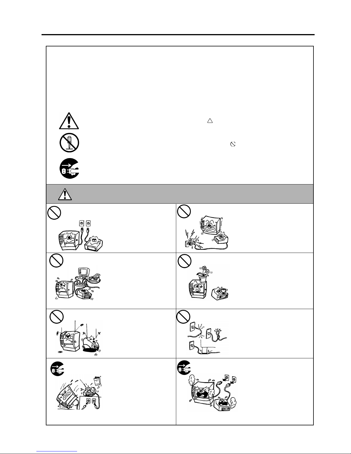
0HDQLQJVRI(DFK6\PERO
This symbol indicates warning items (including cautions).
Specific warning contents are drawn inside the symbol.
(The symbol on the left indicates a general caution.)
This symbol indicates prohibited actions (prohibited items).
Specific prohibited contents are drawn inside or near the
symbol.
(The symbol on the left indicates “no disassembling”.)
This symbol indicates actions which must be performed.
Specific instructions are drawn inside or near the ● symbol.
(The symbol on the left indicates “disconnect the power cord plug from the outlet”.)
This indicates that there is the risk of death or serious injury if the
machines are improperly handled contrary to this indication.
Do not use voltages other than
the voltage (AC) specified on
the rating plate, as this may
cause
fire
or
electric shock
.
Do not plug in or unplug the power
cord plug with wet hands as this
may cause
electric shock
.
If the machines share the same
outlet with any other electrical
appliances which consume
large amounts of power, the
voltage will fluctuate widely
each time these appliances
operate. Be sure to provide an
exclusive outlet for the
machine as this may cause the
machines to
malfunction
.
Do not place metal objects or
water-filled containers such as
flower vases, flower pots or mugs,
etc. on top of the machines. If
metal objects or spilled liquid enter
the machines, this may cause
fire
or
electric shock
.
Do not insert or drop metal,
flammable or other foreign
objects into the machines
through the ventilation slits, as
this may cause
fire
or
electric
shock
.
Do not scratch, damage or modify
the power cords. Also, do not
place heavy objects on, pull on, or
excessively bend the cords, as this
may cause
fire
or
electric shock
.
If the machines are dropped or
their cabinets damaged, first
turn off the power switches and
disconnect the power cord
plugs from the outlet, and then
contact your authorized
TOSHIBA TEC representative
for assistance. Continued use
of the machine in that condition
may cause
fire
or
electric
shock
.
Continued use of the machines in
an abnormal condition such as
when the machines are producing
smoke or strange smells may cause
fire
or
electric shock
. In these
cases, immediately turn off the
power switches and disconnect the
power cord plugs from the outlet.
Then, contact your authorized
TOSHIBA TEC representative for
assistance.
:$51,1*
$Q\RWKHUWKDQWKH
VSHFLILHG$&YROWDJH
LVSURKLELWHG
3URKLELWHG
3URKLELWHG
3URKLELWHG
3URKLELWHG
3URKLELWHG
'LVFRQQHFW
WKHSOXJ
'LVFRQQHFW
WKHSOXJ
Safety Summary
EO1-33029
( )
ii
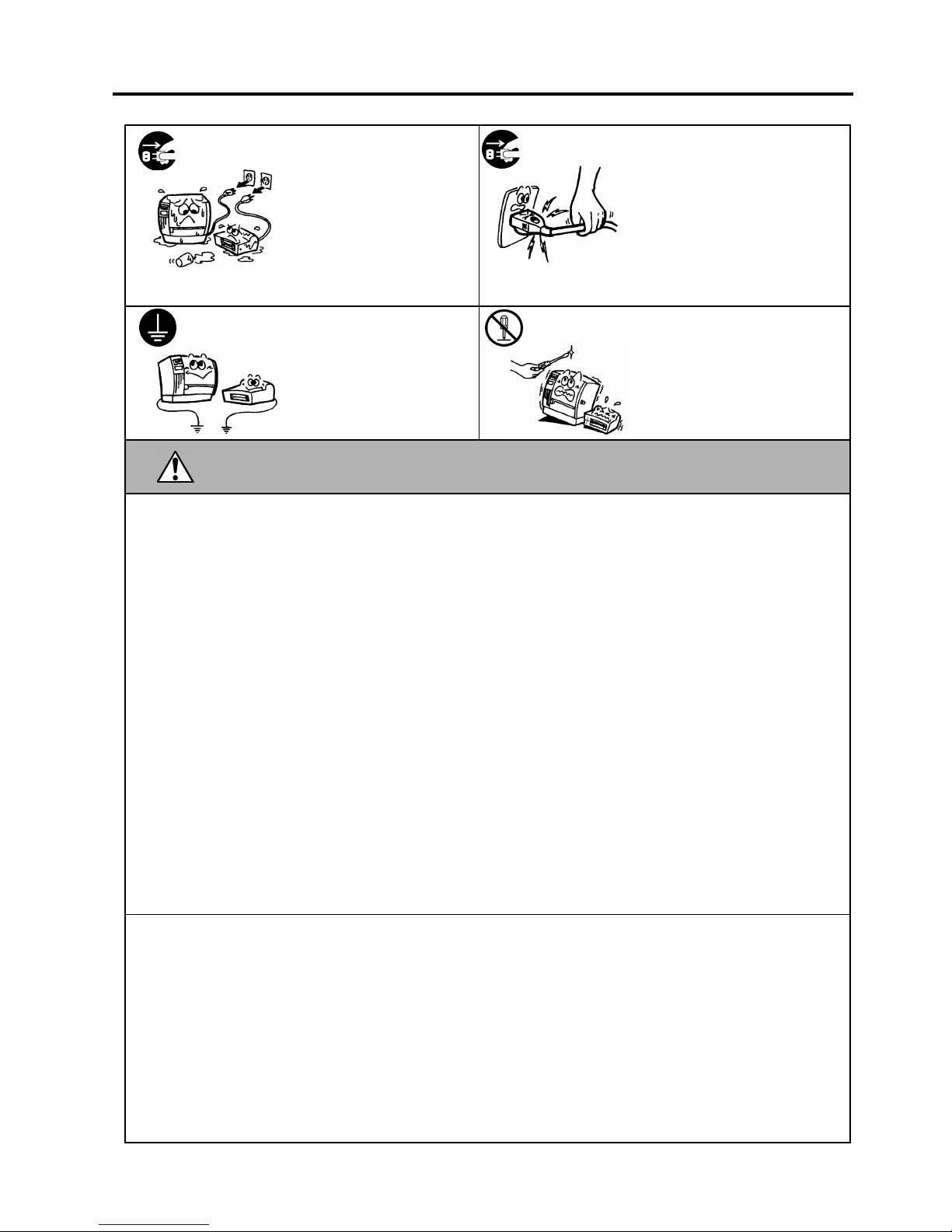
If foreign objects (metal
fragments, water, liquids) enter
the machines, first turn off the
power switches and disconnect
the power cord plugs from the
outlet, and then contact your
authorized TOSHIBA TEC
representative for assistance.
Continued use of the machine in
that condition may cause
fire
or
electric shock
.
When unplugging the power cords,
be sure to hold and pull on the plug
portion. Pulling on the cord portion
may cut or expose the internal wires
and cause
fire
or
electric shock
.
Ensure that the equipment is
properly grounded. Extension
cables should also be grounded.
Fire
or
electric shock
could
occur on improperly grounded
equipment.
Do not remove covers, repair or
modify the machine by yourself.
You may be
injured
by high
voltage, very hot parts or sharp
edges inside the machine.
This indicates that there is the risk of personal
Injury
or
damage
to objects if
the machines are improperly handled contrary to this indication.
3UHFDXWLRQV
The following precautions will help to ensure that this machine will continue to function correctly.
●
Try to avoid locations that have the following adverse conditions:
* Temperatures out of the specification * Direct sunlight * High humidity
* Shared power source * Excessive vibration * Dust/Gas
●
The cover should be cleaned by wiping with a dry cloth or a cloth slightly dampened with a mild
detergent solution. NEVER USE THINNER OR ANY OTHER VOLATILE SOLVENT on the plastic
covers.
●
USE ONLY TOSHIBA TEC SPECIFIED paper and ribbons.
●
DO NOT STORE the paper or ribbons where they might be exposed to direct sunlight, high
temperatures, high humidity, dust, or gas.
●
Ensure the printer is operated on a level surface.
●
Any data stored in the memory of the printer could be lost during a printer fault.
●
Try to avoid using this equipment on the same power supply as high voltage equipment or equipment
likely to cause mains interference.
●
Unplug the machine whenever you are working inside it or cleaning it.
●
Keep your work environment static free.
●
Do not place heavy objects on top of the machines, as these items may become unbalanced and fall
causing injury.
●
Do not block the ventilation slits of the machines, as this will cause heat to build up inside the
machines and may cause fire.
●
Do not lean against the machine. It may fall on you and could cause injury.
●
Care must be taken not to injure yourself with the printer paper cutter.
●
Unplug the machine when it is not used for a long period of time.
5HTXHVW5HJDUGLQJ0DLQWHQDQFH
●
Utilize our maintenance services.
After purchasing the machine, contact
ii
our authorized TOSHIBA TEC representative for assistance
once a year to have the inside of the machine cleaned. Otherwise, dust will build up inside the
machines and may cause a fire or a malfunction. Cleaning is particularly effective before humid rainy
seasons.
●
Our preventive maintenance service performs the periodic checks and other work required to maintain
the quality and performance of the machines, preventing accidents beforehand.
For details, please consult your authorized TOSHIBA TEC representative for assistance.
●
Using insecticides and other chemicals
Do not expose the machines to insecticides or other volatile solvents. This will cause the cabinet or
other parts to deteriorate or cause the paint to peel.
&$87,21
'LVFRQQHFW
WKHSOXJ
&RQQHFWD
JURXQGLQJZLUH
'LVFRQQHFW
WKHSOXJ
1R
GLVDVVHPEOLQJ

EO1-33029
TABLE OF CONTENTS
Page
1. PRODUCT OVERVIEW............................................................................................................1-1
1.1 Introduction...................................................................................................................... 1-1
1.2 Features........................................................................................................................... 1-1
1.3 Unpacking........................................................................................................................ 1-1
1.4 Accessories ..................................................................................................................... 1-2
1.5 Appearance...................................................................................................................... 1-3
1.5.1 Dimensions...................................................................................................................1-3
1.5.2 Front View.....................................................................................................................1-3
1.5.3 Rear View.....................................................................................................................1-3
1.5.4 Operation Panel............................................................................................................1-4
1.5.5 Interior...........................................................................................................................1-4
2. PRINTER SETUP ..................................................................................................................... 2-1
2.1 Precautions...................................................................................................................... 2-1
2.2 Procedure before Operation ............................................................................................ 2-2
2.3 Assembling the Accessories............................................................................................ 2-3
2.3.1 Assembling the Supply Holder Frame...........................................................................2-3
2.4 Connecting the Cables to Your Printer ............................................................................ 2-4
2.5 Connecting the Power Cord............................................................................................. 2-5
2.6 Turning the Printer ON/OFF............................................................................................. 2-6
2.6.1 Turning ON the Printer..................................................................................................2-6
2.6.2 Turning OFF the Printer................................................................................................2-6
2.7 Loading the Media........................................................................................................... 2-7
2.7.1 Installing the Media onto the Supply Holder Unit ..........................................................2-7
2.7.2 Installing the Supply Holder onto the Supply Holder Frame..........................................2-9
2.7.3 Loading Media into the Printer......................................................................................2-9
2.8 Setting Sensor Positions................................................................................................ 2-12
2.8.1 Setting the Feed Gap Sensor .....................................................................................2-12
2.8.2 Setting the Black Mark Sensor....................................................................................2-12
2.9 Loading the Ribbon........................................................................................................ 2-13
2.10 Inserting the Optional PCMCIA Cards........................................................................... 2-14
2.11 Test Print........................................................................................................................ 2-15
3. PRINTER OPERATION............................................................................................................ 3-1
3.1 Overview.......................................................................................................................... 3-1
3.2 Operating Modes ............................................................................................................. 3-1
3.3 Installing the Printer Drivers............................................................................................. 3-3
3.3.1 System Requirements...................................................................................................3-3
3.3.2 Driver Download ...........................................................................................................3-3
3.3.3 Driver Installation..........................................................................................................3-5
3.3.4 Add Printer....................................................................................................................3-7
3.3.5 Uninstalling the TEC B-852 Printer Driver.....................................................................3-8
3.4 Using the B-852 Printer Properties Menus ...................................................................... 3-9
3.4.1 Summary of Properties...............................................................................................3-10
3.4.2 General Properties Tab...............................................................................................3-11
3.4.3 Details Tab..................................................................................................................3-12
3.4.4 Regional Settings Tab.................................................................................................3-15
3.4.5 Page Setup Tab..........................................................................................................3-17
3.4.6 Graphic Tab................................................................................................................3-20
3.4.7 Bar Font Tab...............................................................................................................3-21
3.4.8 Stock Tab....................................................................................................................3-24
3.4.9 Options Tab................................................................................................................3-28
3.4.10 Testing Tab................................................................................................................3-29
3.4.11 About Tab..................................................................................................................3-32

EO1-33029
4. ON LINE MODE......................................................................................................................4-1
4.1 Operation Panel..............................................................................................................4-1
4.2 Operation........................................................................................................................ 4-2
4.3 Reset..............................................................................................................................4-2
4.4 Dump Mode....................................................................................................................4-2
5. MAINTENANCE......................................................................................................................5-1
5.1 Cleaning.........................................................................................................................5-1
5.1.1 Print Head/Platen/Sensors..............................................................................................5-1
5.1.2 Covers and Panels..........................................................................................................5-2
5.1.3 Optional Cutter Module...................................................................................................5-2
5.2 Care/Handling of the Media and Ribbon.........................................................................5-2
6. TROUBLESHOOTING............................................................................................................6-1
6.1 Error Messages..............................................................................................................6-1
6.2 Possible Problems..........................................................................................................6-2
6.3 Removing Jammed Media..............................................................................................6-3
6.4 Threshold Setting ...........................................................................................................6-4
APPENDIX 1 SPECIFICATIONS ................................................................................................ A1-1
A1.1 Printer..........................................................................................................................A1-1
A1.2 Options........................................................................................................................ A1-2
A1.3 Media .......................................................................................................................... A1-2
A1.3.1 Media Type.................................................................................................................A1-2
A1.3.2 Detection Area of the Transmissive Sensor............................................................... A1-3
A1.3.3 Detection Area of the Reflective Sensor ....................................................................A1-4
A1.3.4 Effective Print Area..................................................................................................... A1-4
A1.4 Ribbon......................................................................................................................... A1-5
APPENDIX 2 MESSAGE AND LED............................................................................................ A2-1
APPENDIX 3 INTERFACE.......................................................................................................... A3-1
APPENDIX 4 SYSTEM MODE.................................................................................................... A4-1
A4.1 Operation Panel...........................................................................................................A4-1
A4.2 Overview..................................................................................................................... A4-2
A4.3 Self-Diagnostic Test .................................................................................................... A4-3
A4.4 Printer Parameter Fine Adjustment.............................................................................. A4-5
A4.5 Test Print................................................................................................................... A4-13
A4.6 PCL Emulation Setting............................................................................................... A4-19
A4.7 Additional Information................................................................................................ A4-23
A4.7.1 Self-Diagnostic Test Result Sample and Descriptions.............................................A4-23
A4.7.2 Maintenance Counter/Parameter Check Print Sample and Descriptions................ A4-27
A4.7.3 Magnified Views of Slant Line Pattern...................................................................... A4-30
APPENDIX 5 PRINT SAMPLES ................................................................................................. A5-1
GLOSSARIES
INDEX
CAUTION!
1. This manual may not be copied in whole or in part without prior written permission of TOSHIBA TEC.
2. The contents of this manual may be changed without notification.
3.
Please refer to your local Authorized Service representative with regard to any queries you may have in
this manual.

1. PRODUCT OVERVIEW
EO1-33029
1.1 Introduction
1- 1
1. PRODUCT OVERVIEW
1.1 Introduction
1.2 Features
1.3 Unpacking
Thank you for choosing the TEC B-852 series label/tag printer. This
Owner’s Manual contains valuable information from general set-up to
how to confirm the printer's operation using a test print, and should be
read carefully to help gain maximum performance and life from your
printer. This manual should be kept close at hand for everyday reference.
Please contact your TOSHIBA TEC representative for further
information concerning this manual.
The B-852 printer has the following features:
• A 8.3 inch wide print head installed in such a compact body that the
size of the printer body (except the Supply Holder Unit) is about 1/3
of the B-872 printer.
• The print head block can be fully opened to provide accessability .
• Various kinds of media can be used since the black mark sensors are
located above and under the media passage, respectively, and the
media sensors can be moved from the center to the left edge of the
media.
• When the optional interface board is installed, Web functions such as
remote maintenance and other advanced network functions are
available.
• Superior hardware, including the specially developed 300 dots/inch
(11.8 dots/mm) thermal print head which allows very clear print
quality at a print speed of either 2 inches/sec. (50.8 mm/sec.) or 4
inches/sec. (101.6 mm/sec.).
• Besides the optional cutter module, there is also an optional PCMCIA
Interface Board, Expansion I/O Interface Board, PCL5 Interface
Board Kit, and the KB-80-QM Keyboard Unit.
Unpack the printer as per the Unpacking Instructions supplied with the
printer.
NOTES:
• Check for damage or
scratches on the printer.
However, please note that
TOSHIBA TEC shall have
no liability for any damage
of any kind sustained during
transportation of the
product.
• Keep the cartons and pads
for future transportation of
the printer.
1. PRODUCT OVERVIEW
EO1-33029
1.4 Accessories
1- 2
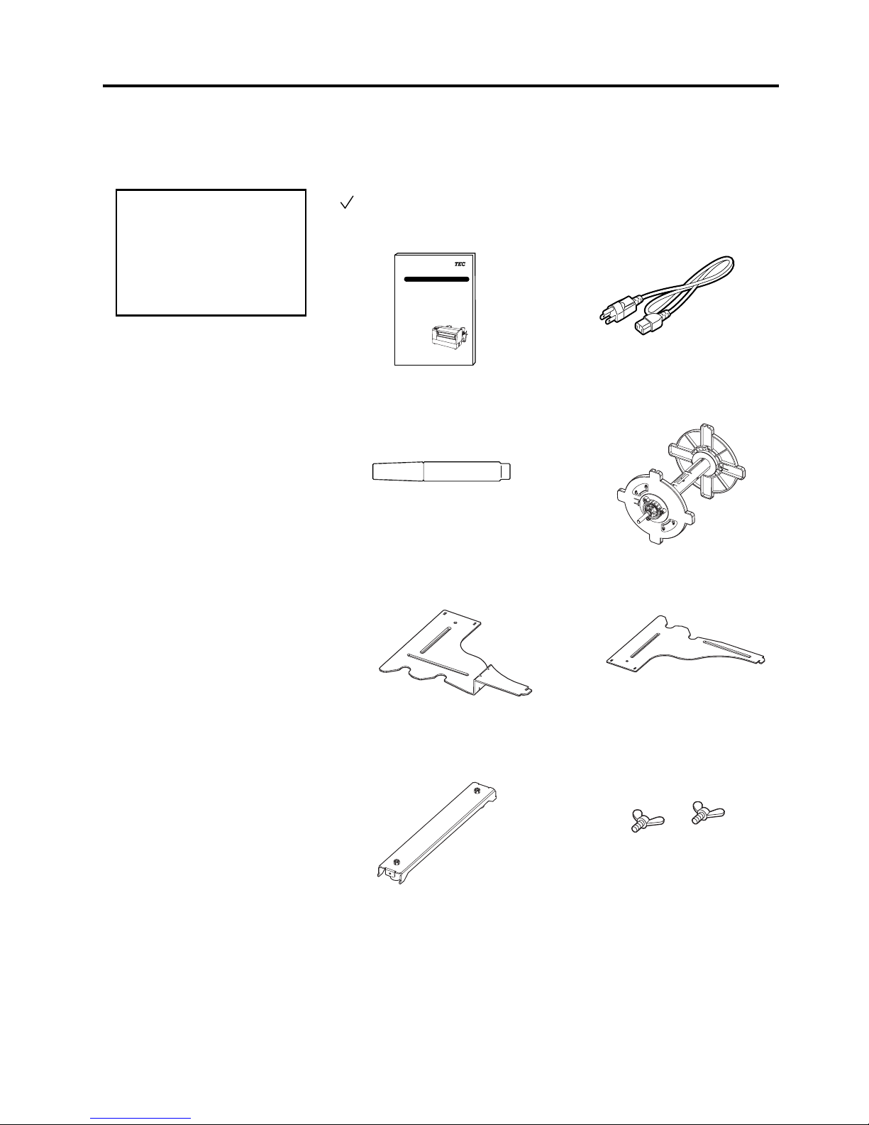
1.4 Accessories
When unpacking the printer, please make sure all accessories are supplied
with the printer.
Owner’s Manual (1 copy)
(Doc./No. EO1-33029)
Print Head Cleaner (1 pc.)
(P/No. 24089500013)
Supply Holder Frame (L) (1 pc.)
(P/No. FMED0035201)
Supply Holder Base (1 pc.)
(P/No. FMBB0063401)
Power Cord (1 pc.)
(P/No. FBCB0030202)
Supply Holder Unit (1 pc.)
(P/No. FMBD0042701)
Supply Holder Frame (R) (1 pc.)
(P/No. FMED0035301)
Wing Bolt M-4x6 (2 pcs.)
(P/No. X20L406130)
CAUTION!
Be sure to use TOSHIBA
TEC approved print head
cleaner. Failure to do this
may shorten the print head
life.
TOSHIBA TEC CORPORATION
TEC Label/Tag Printer
B-850-TS-12-QQ
Owner's Manual
THERMAL HEAD CLEANER
1. PRODUCT OVERVIEW
EO1-33029
1.5 Appearance
1- 3
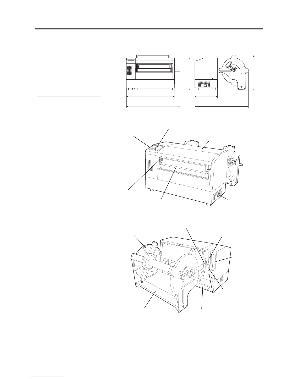
1.5 Appearance
1.5.1 Dimensions
1.5.2 Front View
1.5.3 Rear View
The names of the parts or units introduced in this section are used in the
following chapters.
NOTE:
D
epth is 18.5 inches (470 mm)
when the optional Cutter
M
odule is installed on the
p
rinter.
Dimensions in inches +(mm)
16.9 (429)
16.8 (427)
7.1 (181)
9.6 (243)
10.4 (265)
15.2 (385)
LCD Message Display
Operation Panel
Power Switch
Media Outlet
Top Cover
Supply Holder Frame
Supply Holder Unit
Expansion I/O Interface
Connector (Option)
Parallel Interface
Connector (Centronics)
Serial Interface
Connector (RS-232C)
Keyboard Interface
Connector
PCMCIA Card
Slot (Option)
PCL5 Interface
Connector (Option)
Head Pressure
Adjust Lever
1. PRODUCT OVERVIEW
EO1-33029
1.5 Appearance
1- 4
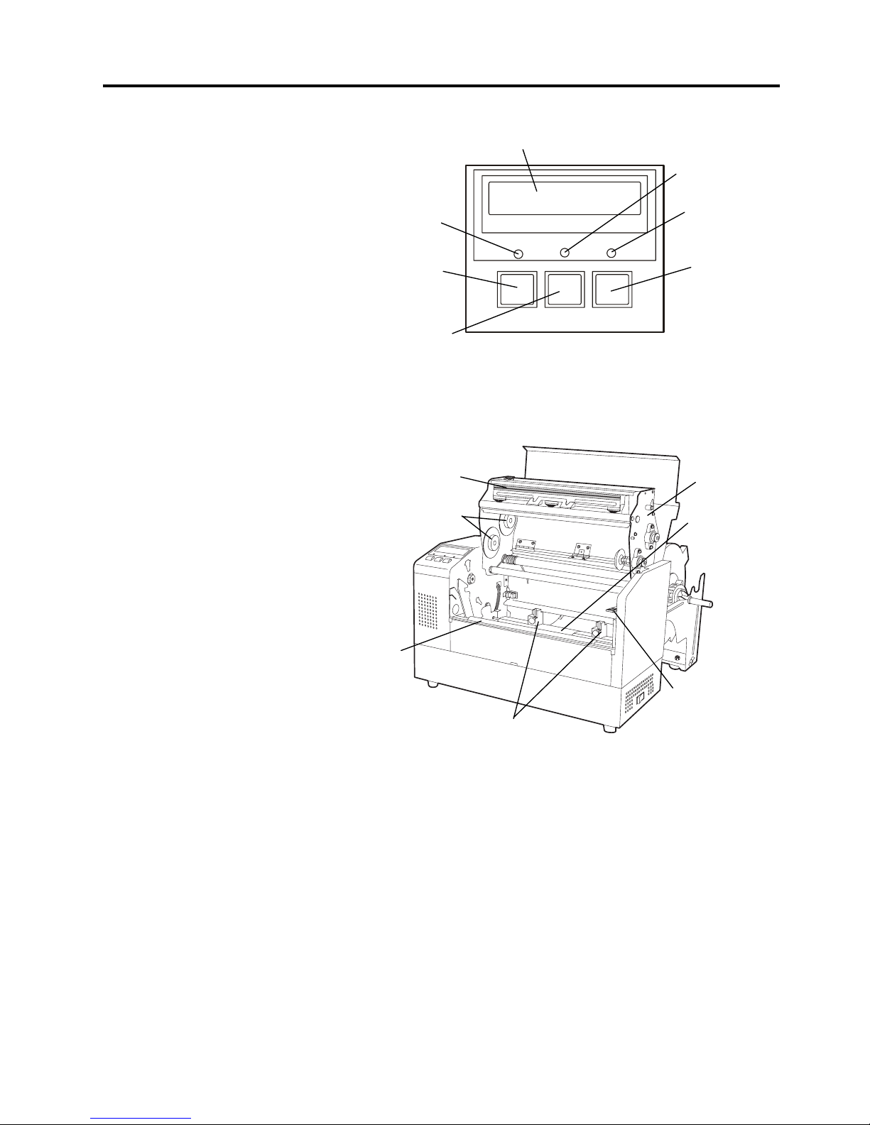
1.5.4 Operation Panel
1.5.5 Interior
Please see Section 4.1 for further information about the Operation Panel.
LCD Message Display
ON LINE LED
(Green)
ERROR LED
(Red)
[PAUSE]
key
POWER LED
(Green)
[FEED]
key
[RESTART]
key
FEED REST AR T P AUSE
POWER ON LINE ERROR
Print Head
Print Head Block
Head Block
Release Lever
Ribbon Holder
Paper Guide
Black Mark/
Feed Gap Sensor
Platen

2. PRINTER SETUP
EO1-33029
2.1 Precautions
2- 1
2. PRINTER SETUP
2.1 Precautions
This section outlines the procedures to setup your B-852 printer prior to
its operation. The section includes precautions, connecting cables,
assembling accessories, loading media and ribbon, inserting the optional
memory card, and performing a test print.
• To insure the best operating environment, and to assure the safety of
the operator and the equipment, please observe the following
precautions.
• Operate the printer on a stable, level, operating surface in a location
free from excessive humidity, high temperature, dust, vibration or
direct sunlight.
• Keep your work environment static free. Static discharge can cause
damage to delicate internal components.
• Make sure that the printer is connected to a clean source of AC Power
and that no other high voltage devices that may cause line noise
interference are connected to the same mains.
• Assure that the printer is connected to the AC mains with a three-
prong power cable that has the proper ground (earth) connection.
• Do not operate the printer with the cover open. Be careful not to
allow fingers or articles of clothing to get caught into any of the
moving parts of the printer especially the optional cutter mechanism.
• Make sure to turn off the printer power and to remove the power cord
from the printer whenever working on the inside of the printer such as
changing the ribbon or loading the media, or when cleaning the
printer.
• For best results, and longer printer life, use only TOSHIBA TEC
recommended media and ribbons.
• Store the media and ribbons in accordance with their specifications.
• This printer mechanism contains high voltage components; therefore
you should never remove any of the covers of the machine as you may
receive an electrical shock. Additionally, the printer contains many
delicate components that may be damaged if accessed by unauthorized
personnel.
• Clean the outside of the printer with a clean dry cloth or a clean cloth
slightly dampened with a mild detergent solution.
• Use caution when cleaning the thermal print head as it may become
very hot while printing. Wait until it has had time to cool before
cleaning. Use only the TOSHIBA TEC recommended print head
cleaner to clean the print head.
• Do not turn off the printer power or remove the power plug while the
printer is printing or while the ON LINE lamp is blinking.

2. PRINTER SETUP
EO1-33029
2.2 Procedure before Operation
2- 2
2.2 Procedure before
Operation
This section describes the outline of the printer setup.
1.
Unpack the accessories and printer from the box.
2.
Refer to Safety Precautions in this manual and set up the printer at a
proper location.
3.
Assemble the Supply Holder Frame and attach it to the rear of the
printer. (Refer to Section 2.3.)
4.
The host computer must have an available serial port or Centronics
parallel port. (Refer to Section 2.4.)
5.
Be sure to insert the power cord plug into an AC outlet. (Refer to
Section 2.5.)
6.
Load the media roll onto the Supply Holder Unit and set it on the
Supply Holder Frame. (Refer to Section 2.7.)
7.
Adjust the position of the Feed Gap Sensor or Black Mark Sensor
depending on the media being used. (Refer to Section 2.8.)
8.
Load the ribbon into the Print Head Block. (Refer to Section 2.9.)
9.
Turn the Power ON. (Refer to Section 2.6.)
10.
Perform a test print. (Refer to Section 2.11.)
11.
Install the Printer Drivers. (Refer to Section 3.)
NOTE:
Use of a Windows Driver will
allow issuing media on the B852 printer in place of a
general laser printer from a
Windows application.
I
nstalling the optional PCL5
interface board in the B-852
p
rinter allows use of the
drivers which support the
PCL5.
The printer can also be
controlled with its own
p
rogramming commands.
Please contact your TOSHIBA
TEC reseller for the
I
nterface/Communication
M
anual.
NOTE:
To communicate with the host
computer, either an RS-232C
cable or Centronics cable is
required.
(1) RS-232C cable: 9 pins
(do not use null modem
cable)
(2) Centronics cable: 36 pins
(3) Expansion I/O cable: 24
pins (Option)
2. PRINTER SETUP
EO1-33029
2.3 Assembling the Accessories
2- 3
2.3 Assembling the
Accessories
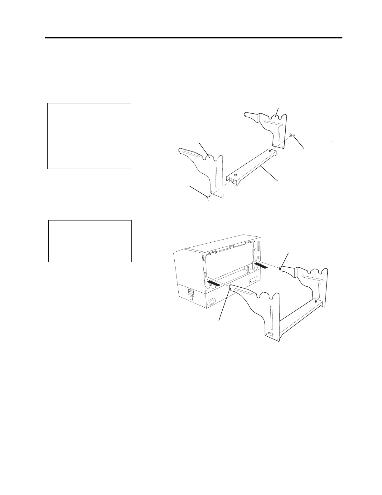
2.3.1 Assembling the
Supply Holder Frame
The following procedure outlines the steps required to assemble the
Supply Holder Frame and attach the frame to the B-852 printer in
preparation for loading the media.
1.
Assemble the Supply Holder Frame (L) and Supply Holder Frame (R)
to the Supply Holder Base using the two M-4X6 Wing Bolts supplied,
as shown below.
2.
Attach the assembled Supply Holder Frame to the rear of the B-852
printer by inserting the hooks of the Frame into the two slots in the
rear of the printer as shown in the figure below.
NOTE:
M
ake sure that the two small
f
langes at each end of the
Supply Holder Base fit into the
small rectangular holes at the
bottom of the Supply Holder
Frames before tightening the
Wing Bolts.
NOTE:
A
fter attaching the supply
holder frame to the printer,
make sure that it is assembled
f
irmly.
Supply Holder Frame (L)
Suppl
y
Holder Frame (R)
Wing Bolt
Wing Bolt
Supply Holder Base
Hook
Hook
2. PRINTER SETUP
EO1-33029
2.4 Connecting the Cables to Your Printer
2- 4
2.4 Connecting the
Cables to Your
Printer
The following paragraphs outlines how to connect the cables from the B852 printer to your host computer, and will also show how to make cable
connections to other devices such as the KB-80-QM keyboard, etc.
Depending on the application software you use to print labels, there are
three possibilities for connecting the printer to your host computer.
These are:
• A serial cable connection between the printer’s RS-232 serial
connector and one of your host computer’s COM ports.
(Refer to APPENDIX 3.)
• A parallel cable connection between the printer’s standard parallel
connector and your host computer’s parallel port (LPT).
• A parallel cable connection between the printer’s optional PCL5
interface connector and your host computer’s parallel port (LPT).
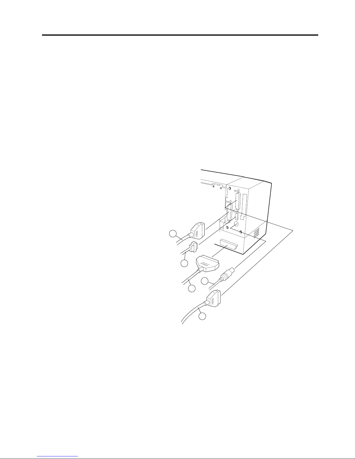
The diagram below shows all the possible cable connections to the
current version of the B-852 printer.
c Parallel Interface Cable (Centronics)
d Serial Interface Cable (RS-232C)
e PCL5 Interface Cable (Option)
f KB-80-QM Keyboard Interface Cable (Option)
g Expansion I/O Interface Cable (Option)
1
3
4
2
5
2. PRINTER SETUP
EO1-33029
2.5 Connecting the Power Cord
2- 5
2.5 Connecting the
Power Cord
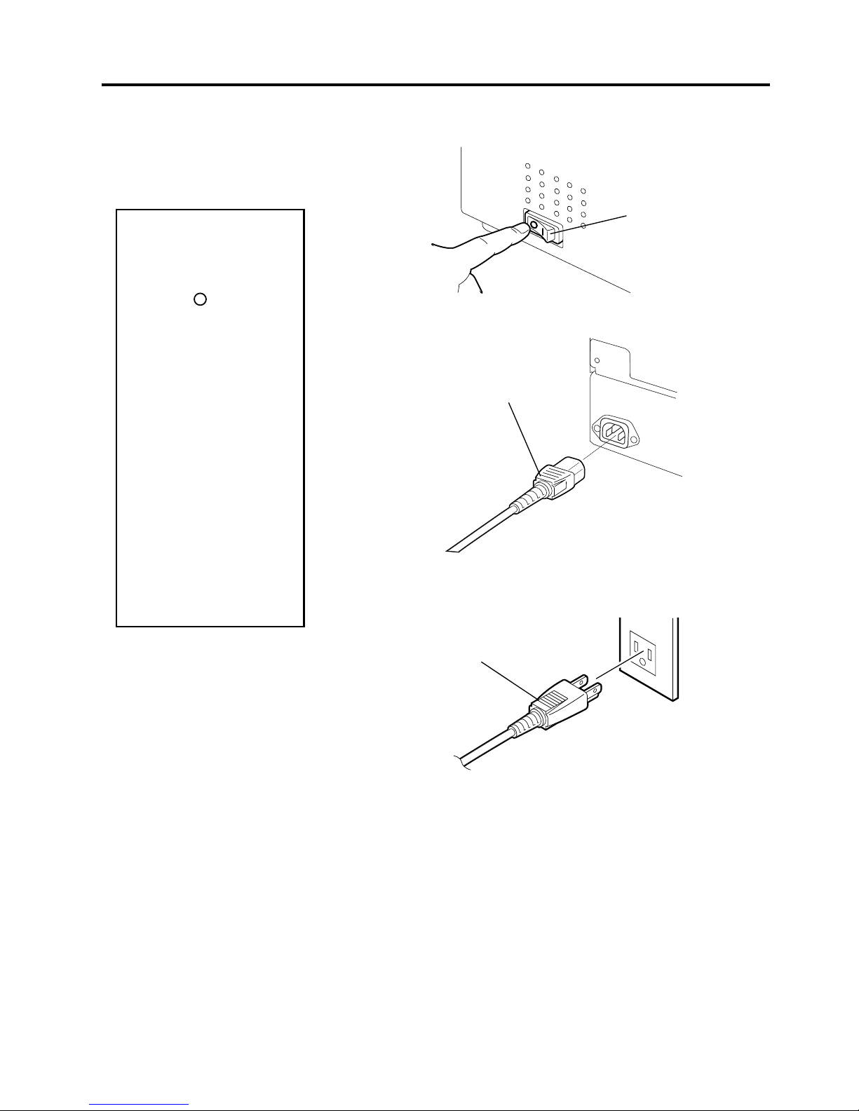
1
. Make sure that the printer power switch is in the off position.
2.
Connect the Power Cord to the printer as shown in the figure below.
3.
Plug the other end of the Power Cord into a grounded outlet as
shown in the figure below.
CAUTION!
1. Make sure that the
printer power switch is
turned to the off
position
before
connecting the power
cord to prevent
possible electric shock
or damage to the
printer.
2. Use only the power
cord supplied with the
printer. Use of any
other cord may cause
electric shock or fire.
3. Connect the power
cord to a three-prong
outlet only, with the
third prong being a
good ground (earth)
connection.
Power Cord
Power Switch
Power Connector
2. PRINTER SETUP
EO1-33029
2.6 Turning the Printer ON/OFF
2- 6
2.6 Turning the Printer
ON/OFF
2.6.1 Turning ON the Printer
2.6.2 Turning OFF the
Printer
When the printer is connected to your host computer it is good practice to
turn the printer ON before turning on your host computer and turn OFF
your host computer before turning off the printer.
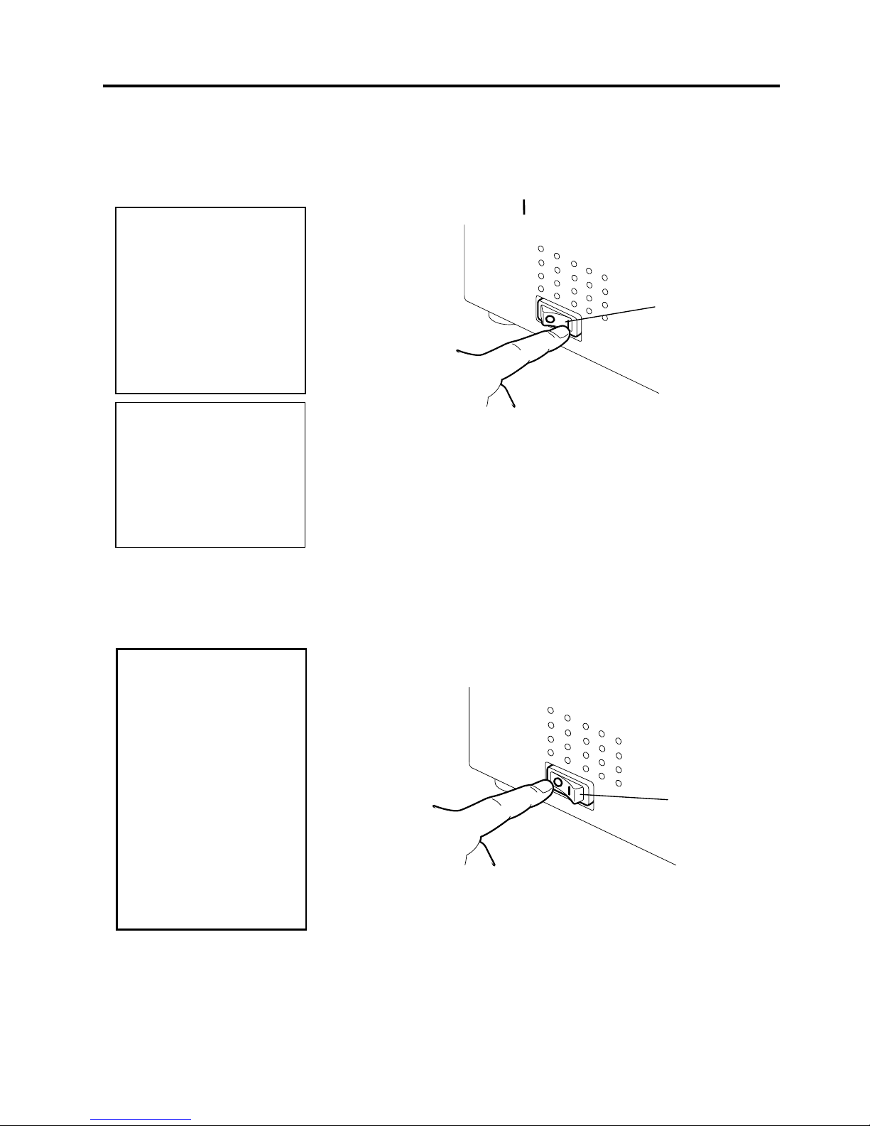
1.
To turn ON the printer power, press the power switch as shown in the
diagram below. Note that ( ) is the power ON side of the switch.
2.
Check that the ON LINE message appears in the LCD Message
Display and that the ON LINE and POWER LED lights are
illuminated.
1.
Before turning off the printer power switch verify that the ON LINE
message appears in the LCD Message Display and that the ON LINE
LED light is on and is not flashing.
2.
To turn OFF the printer power press the power switch as shown in the
diagram below. Note that ( { ) is the power OFF side of the switch.
CAUTION!
Use the power switch to
turn the printer On/Off.
Plugging or unplugging
the power cord to turn
the printer On/Off may
cause fire, an electric
shock, or damage to the
printer.
CAUTION!
•
Do not turn off the
printer power while the
media is being printed
as this may cause a
paper jam or damage
to the printer.
•
Do not turn off the
printer power while the
ON LINE light is
blinking as this may
cause damage to your
host computer.
NOTE:
I
f an error message appears
in the display instead of the
ON LINE message or the
ERROR LED lamp is
illuminated, go to Chapter
6.1, Error Messages.
Power Switch
Power Switch
2. PRINTER SETUP
EO1-33029
2.7 Loading the Media
2- 7
2.7 Loading the Media
2.7.1 Installing the Media
onto the Supply Holder
Unit
The following procedure will outline the steps required to install the
media onto the Supply Holder Unit and adjust its position in the Supply
Holder Frame at the rear of the B-852 printer. The procedure will then
show the steps to properly load the media into the printer so that it feeds
straight and true through the printer.
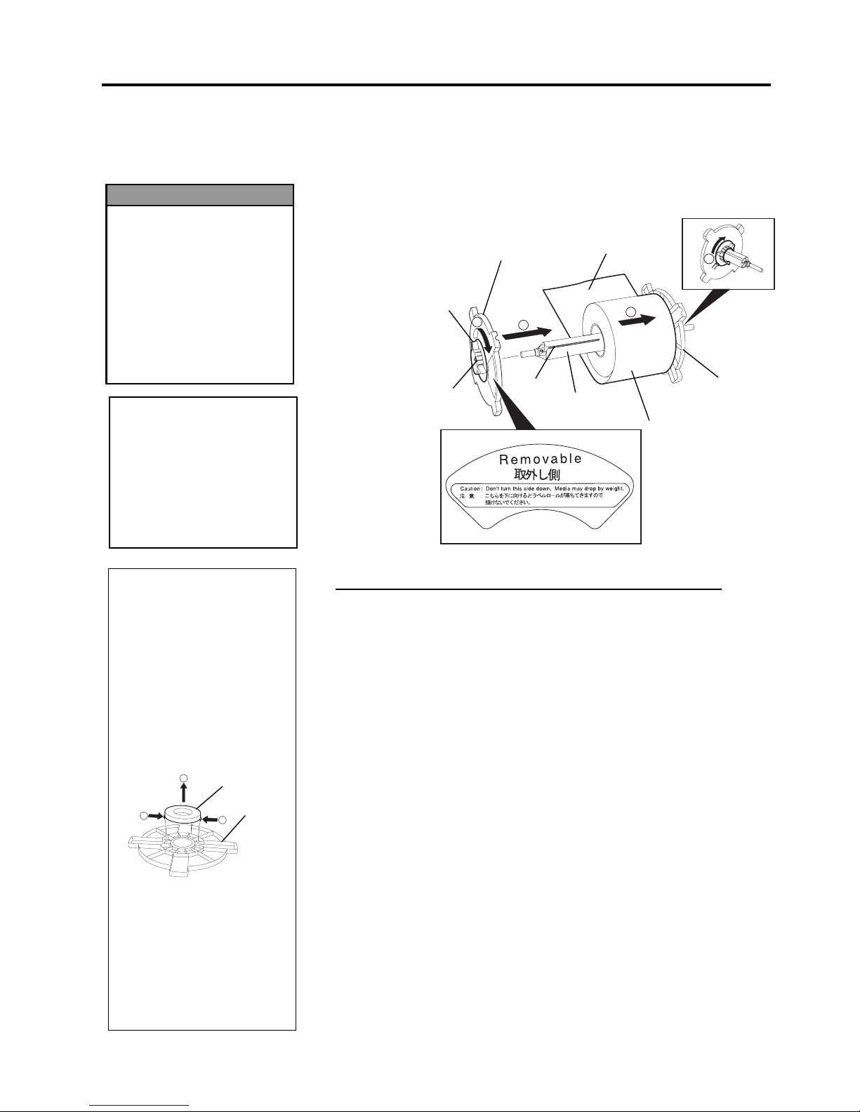
The figure below shows the assembled Supply Holder Unit and the
paragraphs that follow show the step-by-step procedures to disassemble
the Supply Holder Unit, install the media onto the Supply Shaft, then
reassembling the Supply Holder Unit so that the auto centering
mechanism will automatically center the media on the Supply Shaft.
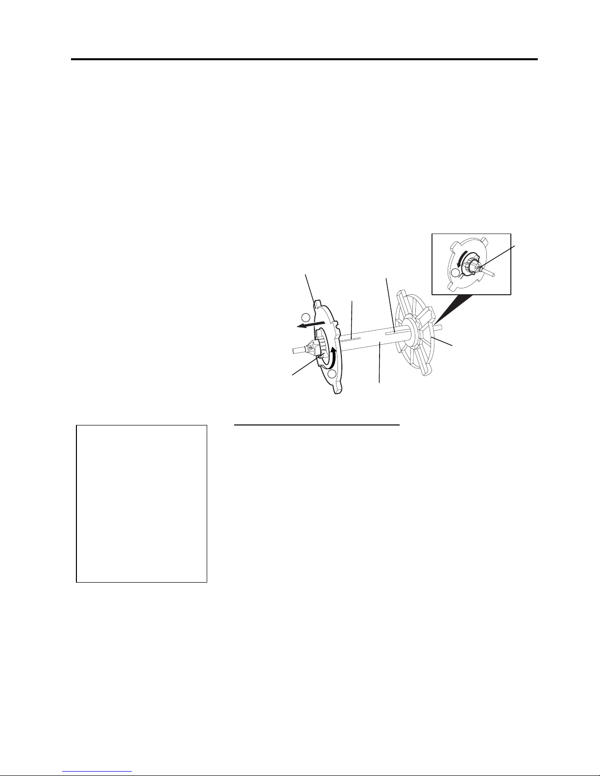
Disassembling the Supply Holder Unit
1.
Position the Supply Holder Unit as shown in the above diagram so
that the Non-removable Supply Holder is at the right.
2.
Rotate the green Supply Holder Locking Knob in the direction of
arrow
c
(counterclockwise) to loosen the Removable Supply Holder.
3
. Slide the Removable Supply Holder in the direction of arrow
d
to
remove it from the Supply Shaft.
4
. Rotate the green Supply Holder Locking Knob in the direction of
arrow
e
(counterclockwise) to loosen the Non-removable Supply
Holder.
5.
Slide the Non-removable Supply Holder all the way to the end of the
Supply Shaft until it stops.
NOTES:
1. The Non-removable Supply
Holder is the one that
slides in the wide slot while
the Removable Supply
Holder is the one that
slides in the narrow slot.
2. Do not turn the supply
holder locking knob
counter-clockwise too far,
or it may come off the
supply holder Unit.
1
2
3
Non-removable
Suppl
y
Holder
Removable
Supply Holder
Green Supply Holder
Locking Knob
Wide Slot
Narrow Slot
Stopper
Supply Shaft
2. PRINTER SETUP
EO1-33029
2.7 Loading the Media
2- 8
2.7.1 Installing the Media
onto the Supply Holder
Unit (cont.)
The diagram below, and the steps that follow, show the procedures for
installing the Media onto the Supply Shaft and reassembling the Supply
Holder Unit. Be sure to follow the step-by-step procedure exactly or the
auto centering mechanism may not work properly.
Installing the Media and reassembling the Supply Holder Unit
1.
Place the media roll onto the Supply Shaft with the media feeding
from the bottom as shown in the diagram above.
c
2.
Align the tab of the Removable Supply Holder with the Slot in the
Supply Shaft, then reinstall the Removable Supply Holder by sliding it
onto the Supply Shaft as shown in the figure above.
3.
Holding the reassembled Supply Holder Unit in your right hand, apply
pressure only to the reinstalled Removable Supply Holder to push it in
the direction of arrow
d
, causing the auto centering mechanism to
center the media on the Supply Shaft.
4.
Tighten the green Supply Holder Locking Knob for the Removable
Supply Holder by turning it in the direction of arrow
e
.
5.
Tighten the green Supply Holder Locking Knob for the Non-
removable Supply Holder by turning it in the direction of arrow
f
.
NOTES:
1. This supply holder accepts
four sizes of media core: 38
mm, 40 mm, 42 mm and 76.2
mm.. When using a media roll
of 38 mm, 40 mm, or 42 mm,
remove the spacers from the
supply holders by pushing
both hooks of the spacer.
Keep the removed spacers
safe.
2. Use only inside wound label
stock. Outside wound label
stock may not feed properly.
Use outside wound label stock
at your own risk.
3.
Do not over-tighten the
green supply holder locking
knob.
CAUTION!
When installing the media
roll, do not push on the
Non-removable Supply
Holder as this will result in
the media roll not being
properly centred.
Supply
Holder
2
3
4
1
Non-removable
Supply Holder
Removable
Supply Holder
Media Roll
Supply Shaft
Print Side
Slot
Tab
1
1
2
Spacer
If you turn the
Removable Supply
Holder side down after
loading the media, the
media may drop by
weight. You might be
injured by the dropped
media.
WARNING!
Green Supply
Holder
Locking Knob
2. PRINTER SETUP
EO1-33029
2.7 Loading the Media
2- 9
2.7.2 Installing the Supply
Holder Unit onto the
Supply Holder Frame
2.7.3 Loading Media into
the Printer
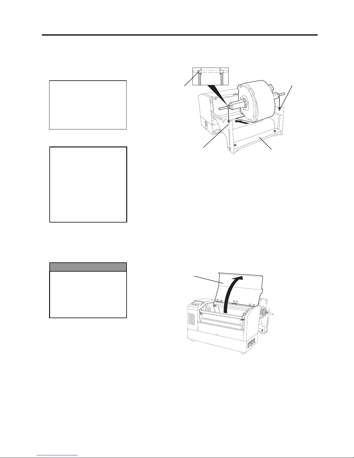
1.
Insert the assembled Supply Holder Unit into the rear notches of the
Supply Holder Frame as shown in the diagram below.
2.
Now feed the media from the bottom of the media roll into the media
slot at the rear of the printer as shown.
The following paragraphs outlines how to properly install the media into
the printer from the Supply Holder Unit that has been installed in the
previous steps.
1.
Raise the Top Cover as shown in the diagram below.
CAUTION!
The reassembled Supply
Holder Unit and media roll
may be quite heavy, so
be careful not to pinch
y
our fingers when
installing the Supply
Holder Unit onto the
Supply Holder Frame.
NOTE:
M
ake sure that the brass
bushings of the Supply Shaft
are seated into the notches so
that the entire Supply Holder
Unit rotates smoothly.
Rear Notch
Supply Holder Frame
Brass Bushing
Rear Notch
Top Cover
The Top Cover can be
opened during the
operation for control
purposes only. It should
be closed during normal
operation.
WARNING!
2. PRINTER SETUP
EO1-33029
2.7 Loading the Media
2-10
2.7.3 Loading Media into the
Printer (Cont.)
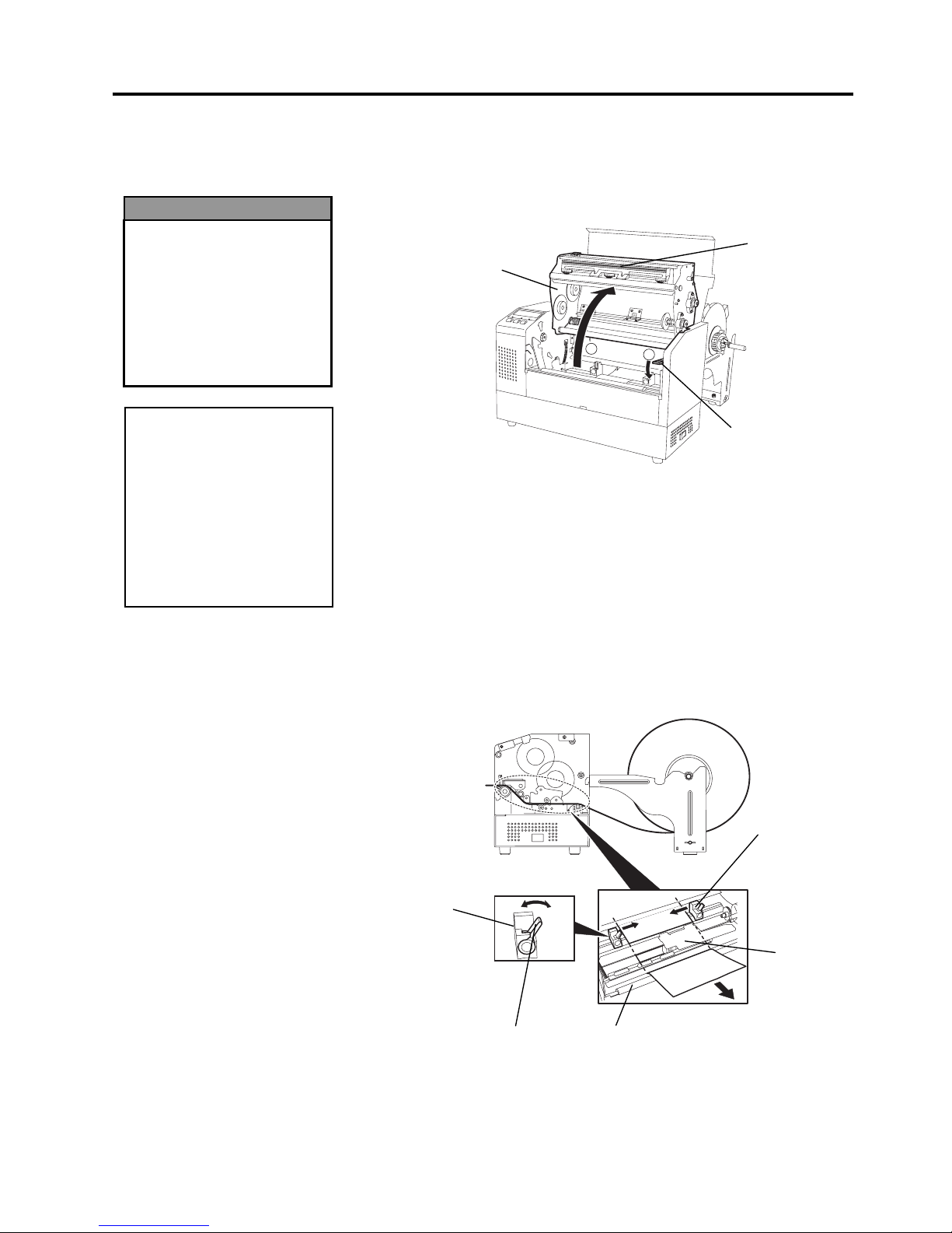
2.
Release the Print Head Block by pressing down on the Head Block
Release Lever
c
as shown below.
3.
Raise the Print Head Block to its fully open position as shown by the
arrow
d
in the diagram below.
4.
Release the Paper Guide Locking Levers on the two Paper Guides as
shown in the figure below.
5.
Grasp the right hand Paper Guide and move it to the right to open the
Paper Guides wide enough to accept the media.
6.
Feed the media between the two guides.
7.
Feed the paper under the Upper Sensor Ass’y and pull the paper until
it extends past the Platen. (until it extends past the cutter outlet when
the optional Cutter Module is attached.)
8.
Grasp the right Paper Guide and move it to the left to close both Paper
Guides and automatically center the media.
9.
Press the Paper Guide Locking Levers to lock the Paper Guides in
place.
CAUTION!
Be careful not touch the
Print Head Element when
raising the Print Head
Block. Failure to do this
may cause missing dots
by static electricity or
other print quality
problems.
1
2
Head Block
Release Lever
Print Head Block
Print Head
Element
Lock
Free
Platen
Paper Guide
Locking Lever
Paper Guide
Upper Sensor
Ass’y
Paper Guide
•
The Print Head may
become hot. Do not
touch the Print Head.
•
Risk of injuries. Do not
touch moving parts.
Disconnect the mains
before maintenance of
ribbon and media.
WARNING!
2. PRINTER SETUP
EO1-33029
2.7 Loading the Media
2-11
2.7.3 Loading Media into the
Printer (Cont.)
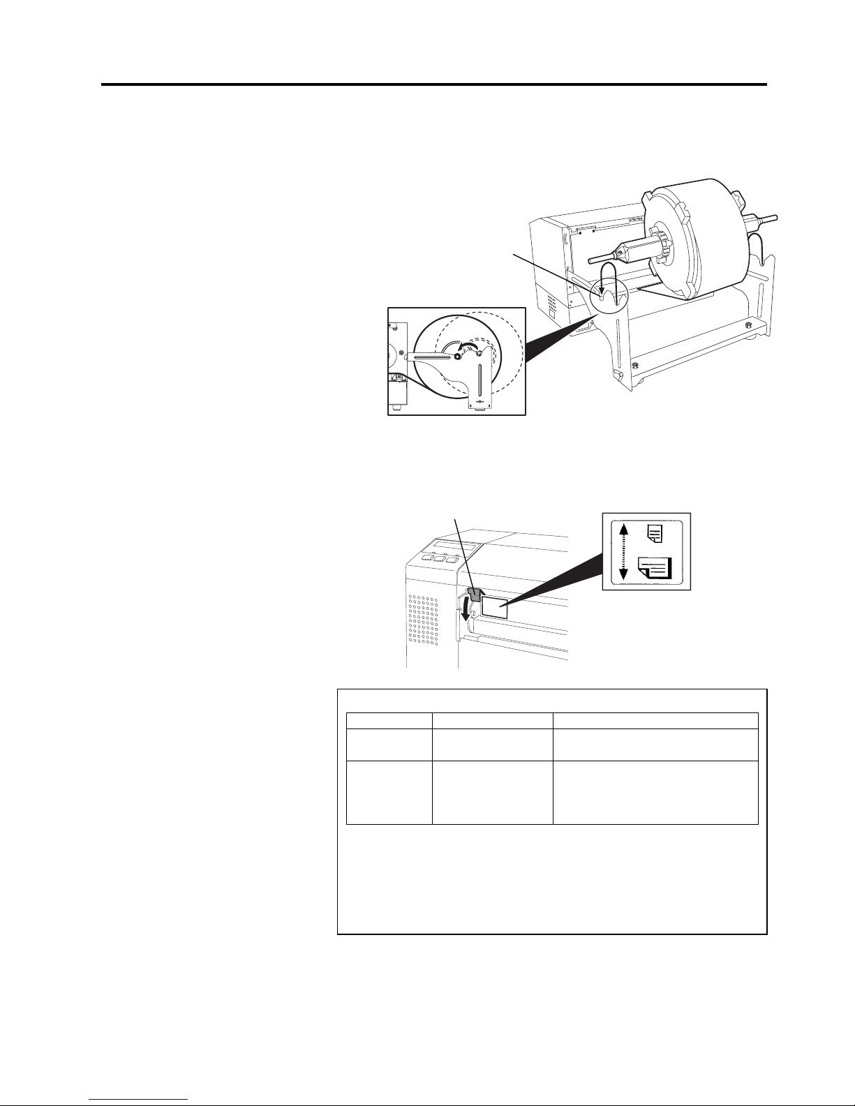
10.
After loading the media, don’t forget to move the Supply Holder
Unit to the forward notches of the Supply Roll Frame as shown
below.
11.
If you are using labels or thick tag paper, then it may be necessary to
increase the head pressure by lowering the Head Pressure Adjust
Lever in the figure below.
Head Pressure Adjust Lever
Forward Notch
NOTE: Head Pressure Adjust Lever Position
Lever position Head pressure Available media
UP Low
•Thin tag paper
•Narrow media
DOWN High
•Label
•Thick tag paper
•Wide media
•Full width media
•
When using full width media, be sure to turn the Head Pressure Adjust
Lever to DOWN, regardless of the thickness.
•
For all kinds of media except the full width media, turn the Head Pressure
Adjust Lever to UP, if the print quality is to be ensured
.
•
If the print tone is light when using thin tag paper, turn the Head Pressure
Adjust Lever to DOWN.
UP
DOWN
2. PRINTER SETUP
EO1-33029
2.8 Setting Sensor Positions
2-12
2.8 Setting Sensor
Positions
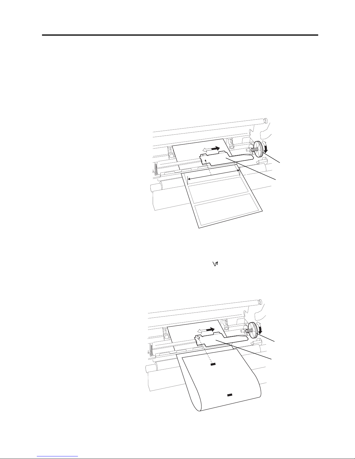
2.8.1 Setting the Feed Gap
Sensor
2.8.2 Setting the Black Mark
Sensor
After loading the media, as outlined in the previous paragraphs, it will
then be necessary to set the Media Sensors used to detect the print start
position for label or tag printing.
1.
With the Print Head Block raised as described in section 2.7.3, pass
the labels under the Upper Sensor Ass’y as shown in the figure below.
2.
Rotate the Green Sensor Adjust Gear to move the Sensor Ass’y to the
left or right to center the arrow (
↑
) over the label.
3.
With the sensor set to the center of the labels, it will best detect the
gap between labels even if the labels are round.
1.
If the Black Mark is printed on the top of the tag media then simply
rotate the Green Sensor Adjust Gear to move the Sensor Ass’y so that
the Black Mark Indicator ( ) is directly in line with the Black Mark
on the top of the paper.
2.
If the Black Mark is printed on the bottom of the tag media then fold
the media back to be able to see the Black Mark and its relationship to
the Sensor Ass’y as shown in the figure below.
Upper Sensor Ass’y
Green Sensor
Adjust Gear
Upper Sensor Ass’y
Green Sensor
Adjust Gear

2. PRINTER SETUP
EO1-33029
2.9 Loading the Ribbon
2-13
2.9 Loading the Ribbon
1.
Raise the Top Cover and release and raise the Print Head Block as
described in section 2.7.3, steps 1 and 2.
2.
Hold the Ribbon Supply Roll in your left hand and the Ribbon Take
up Roll in your right hand.
3.
Install the Ribbon Supply Roll into the Print Head Block as shown in
the figure below and described in the following paragraphs.
4.
Step 1, engage the end of the Ribbon Supply Roll Core to the Ribbon
Core Guide
c
and push to compress the Ribbon Spring.
5.
Step 2, engage the opposite end of the Ribbon Supply Roll Core to the
Green Ribbon Winding Core
d
releasing pressure to relax the
Ribbon Spring.
6. Rotate the Green Ribbon Winding Core to lock the Ribbon Supply
Roll into position.
e
7.
Repeat steps 4 through 6 with the Ribbon Take-up Roll, locking it in
place also.
8.
Take up any slack in the ribbon by rotating the Green Ribbon Winding
Core on the Ribbon Take-up Roll in the direction of arrow
c
.
9.
Close the Print Head Block and lock it in place by pressing at
locations
d
and e in the figure below.
NOTE:
B
e sure to remove any slack in
the ribbon. Printing with a
wrinkled ribbon will lower the
p
rint quality
STEP 1
STEP2
3
1
2
Ribbon Core Guide
Green Ribbon Winding Core
Ribbon Spring
Ribbon Supply Roll
Ribbon Take-up Roll
1
2
3
Green Ribbon
Winding Core
•
The Print Head may
become hot. Do not
touch the Print Head.
•
The Top Cover can be
opened during the
operation for control
purposes only. It
should be closed during
normal operation.
•
Risk of injuries. Do not
touch moving parts.
Disconnect the mains
before maintenance of
ribbon and media.
WARNING!
2. PRINTER SETUP
EO1-33029
2.10 Inserting the Optional PCMCIA Cards
2-14
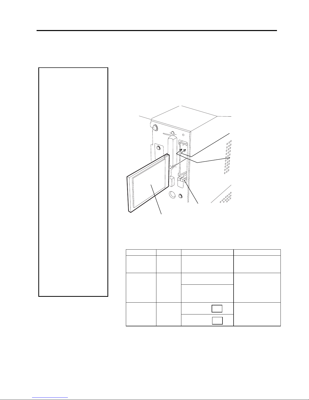
2.10 Inserting the
Optional PCMCIA
Cards
When the optional PCMCIA interface board is installed into the B-852
printer, there will be two PCMCIA slots available as shown in the figure
below. This allows for the use of Flash Memory Type Cards or I/O type
Cards such as LAN Cards. The following paragraphs outline how to
insert PCMCIA cards.
1.
Make sure that the printer’s power switch is in the OFF position.
2.
Hold the PCMCIA Card so that the model name printed side faces
right. Insert the card into the proper slot until the Eject Button pops
out.
3.
The following PCMCIA cards can be used.
Type Maker Description Remarks
ATA Card
San Disk
Hitachi
A card conforming to
the PC card ATA
standard
----------
Ether Link III 3C589D
PC card
LAN Card 3 COM
Megahertz®
10M bps LAN PC Card
3CCE589ET Series
Install into the slot
(1) only. (This card
installed into the slot
(0) will not work.)
Flash
Memory
Card (4 MB)
Maxell
----------
CAUTION!
1. To protect PC cards,
discharge static
electricity from your body
by touching the metal
cabinet of the printer
before touching the card.
2. Before inserting or
removing a PCMCIA
card make sure that the
printer’s power is turned
off.
3. Be sure to protect
PCMCIA Cards when not
in use by putting them
into their protective
covers.
4. Do not subject the card
to any shocks or
excessive force nor
expose the card to
extremes in temperature
or humidity
5
. The card may be
inserted into the slot
halfway even in the
wrong orientation.
However, the slot is
safety designed so that
the card will not seat
against the connector
pins.
Slot 1:
(I/O type cards such as
LAN cards
)
Slot 0:
(Memory type cards only)
Eject Button
Model Name Printed Side
CC
EF-4M-TB
DC
EF-4M-TB

2. PRINTER SETUP
EO1-33029
2.11 Test Print
2-15
2.11 Test Print
The following test procedure allows you to perform a print test to verify that
the printer is operating correctly. During the running of this test, the
printer
will first issue a blank page of media to allow the sensors to detect the
Black Mark or Label Gap. Then it will print five pages of slanted lines
followed by five pages of sample bar codes then finishing by printing five
pages that contain characters of various sizes.
Issue count = 5 of each kind of label
Print method = Thermal Transfer (ribbon required)
Print speed = 4” per second
Sensor = Transmissive (Feed Gap Sensor) or Reflective (Black Mark
sensor).
Type of print = Batch (No cut)
Print Length = 76 mm
The following paragraphs guide you through the diagnostic procedure for
test label printing. Please follow the step-by-step procedures exactly for
best results.
1.
Load the media. For best results, use media that is 76 mm or longer in
length.
2.
Press and hold the
[FEED]
and
[PAUSE]
keys while turning on the
printer power switch. The LCD Message Display will show the
following message.
3.
Press the
[FEED]
key three times to advance to the test print mode as
indicated by the following message in the LCD Message Display.
4.
Press the
[PAUSE]
key and the LCD Message Display will display
the following message.
5.
Press the
[RESTART]
key and the LCD Message Display will change
to show the following message.
6.
When the media loaded is:
Tag paper utilizing the Black Mark Sensor (Reflective Sensor)
→ Continue on to the next step 7.
Labels utilizing the Feed Gap Sensor (Transmissive Sensor)
→ Press the
[RESTART]
key again, and proceed to step
10.
7.
Press the
[PAUSE]
key and the printer will issue one blank label and
will then print five labels of slant lines and the LCD Message Display
will continue to display the following message.
!',$*$
!7(6735,17
35,17&21',7,21
$87235,175()/
$87235,175()/

2. PRINTER SETUP
EO1-33029
2.11 Test Print
2-16
2.11 Test Print (cont.)
8.
Press the
[PAUSE]
key again and the printer will now print five
labels of sample bar codes lines and the LCD Message Display will
continue to display the following message.
9.
Press the
[PAUSE]
key again and the printer will now print five
labels of characters of various sizes and the LCD Message Display
will return to showing the test print start message as shown below.
10.
Upon pressing the
[RESTART]
key for the second time in step 6,
the LCD Message Display will change to that shown below.
11.
Press the
[PAUSE]
key and the printer will issue one blank label
and will then print five labels of slant lines and the LCD Message
Display will continue to display the following message.
12.
Press the
[PAUSE]
key again and the printer will now print five
labels of sample bar codes lines and the LCD Message Display will
continue to display the following message.
13.
Press the
[PAUSE]
key again and the printer will now print five
labels of characters of various sizes and the LCD Message Display
will return to showing the test print start message as shown below.
14.
If necessary, the print test may now be repeated from step 4.
15.
When you have finished performing the test print operation, turn the
printer’s power OFF then back to ON and check that the LCD
Message Display shows
ON LINE
and that the
ON LINE
and
POWER
LED lights are illuminated.
NOTE:
I
f an error occurs during the
p
rint test the printer will
display an error message and
stop printing. Refer to Chapte
r
6.1 for a definition of error
messages.
The error may be cleared by
p
ressing the
[PAUSE]
key but
the test print will not be
resumed and the LCD message
display will return to showing:
<1> DIAG. V1.0A
$87235,175()/
!7(6735,17
$87235,1775$1
$87235,1775$1
$87235,1775$1
!7(6735,17
NOTE:
When the
[PAUSE]
key is
p
ressed in Step 10, the printer
will enter each print pattern
detailed on the setting menu
mode. To exit, press the
[FEED]
and
[RESTART]
keys
at the same time.
2. PRINTER SETUP
EO1-33029
2.11 Test Print
2-17
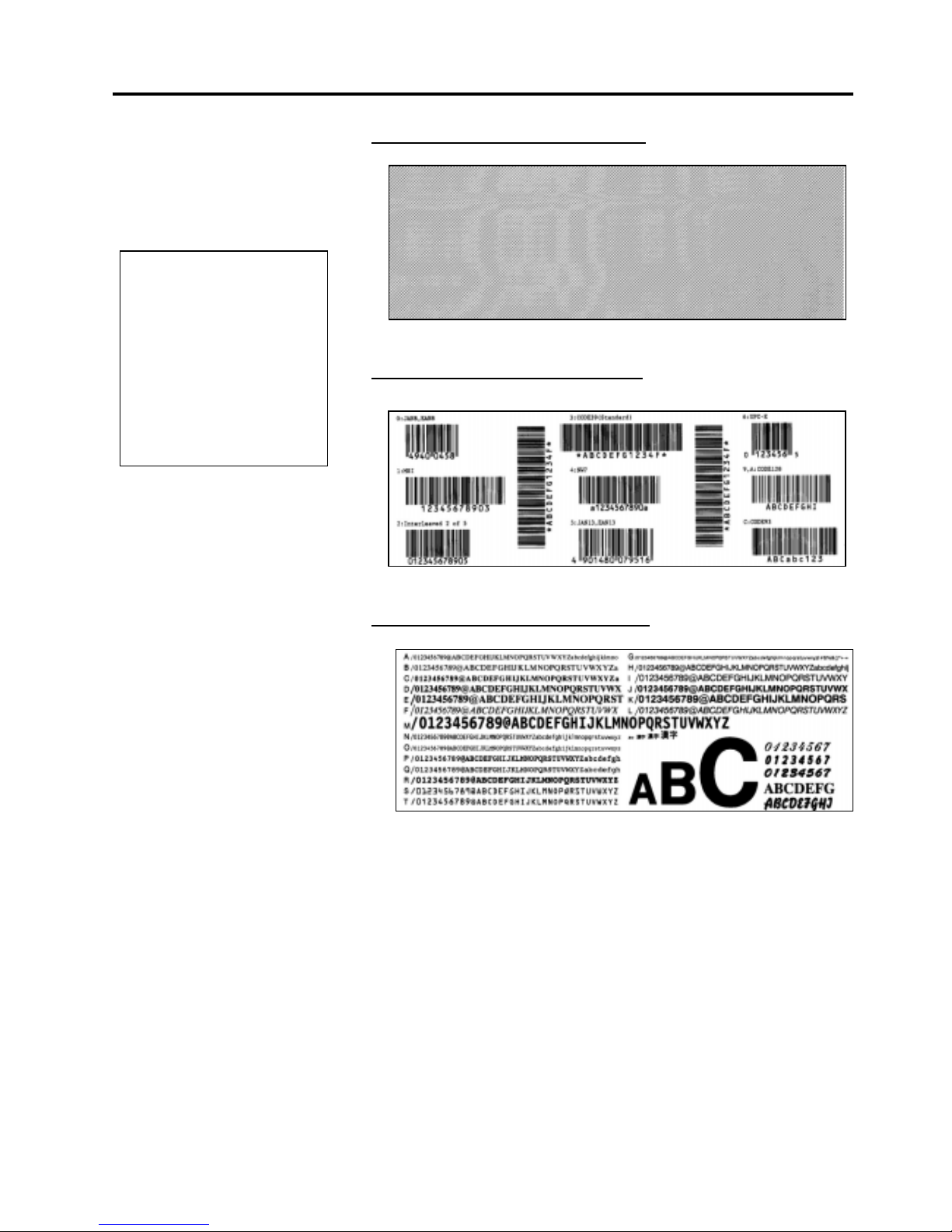
2.11 Test Print (cont.)
Example of the slant line test print label
Example of the bar code test print label
Example of the character test print label
NOTE:
The five printed labels of bar
codes and the five printed
labels of characters will be
76mm in length regardless of
the actual size of the labels
installed. However the slant
line printed labels will be the
same size as the installed
labels.
3. PRINTER OPERATION
EO1-33029
3.1 Overview
3- 1
3. PRINTER OPERATION
3.1 Overview
3.2 Operating Modes
This section provides a functional overview of how the printer receives print
data from your host computer and how it will operate in the various
operating conditions. This section also shows you how to install the TEC
Printer Drivers into your computer.
Labels will be created on the host computer connected to your printer,
using either a commercially available label creation program or using the
TEC Command Program Language. Or if the optional PCL5 Interface
Board has been installed, the printer will be able to print from any
software using the HP-PCL5 Printer Command Language. The label
information sent from your host computer will consist of a series of
commands that inform the printer of the labels size, layout, orientation,
and number of copies to print and will also contain the print data
including scaleable text, graphics, and bar codes. The printer electronics
will decode the commands and manipulate the data to create a bit graphic
image of the label that will be stored in the printer’s memory . The printer
electronics will then transfer the image as a series of dots, one line at a
time, to the thermal print head.
The thermal print head consists of a line of 2560 thermal elements with
each element shaped like a tiny dot. The dot line is 8.5 inches (216.8
mm) in length resulting in a dot density of 300 DPI. As the paper is
advanced through the printer by the paper feed mechanism, the thermal
head continuously prints the image as a series of dot lines at a resolution
of 300 dots per inch, horizontally and vertically.
Precision feeding and back feeding of the label or tag stock is
accomplished through the use of specialized stepping motors and photosensors. The label gap sensor or the black mark sensor tells the printer
electronics when the label or tag stock is properly positioned under the
head for accureate printing.
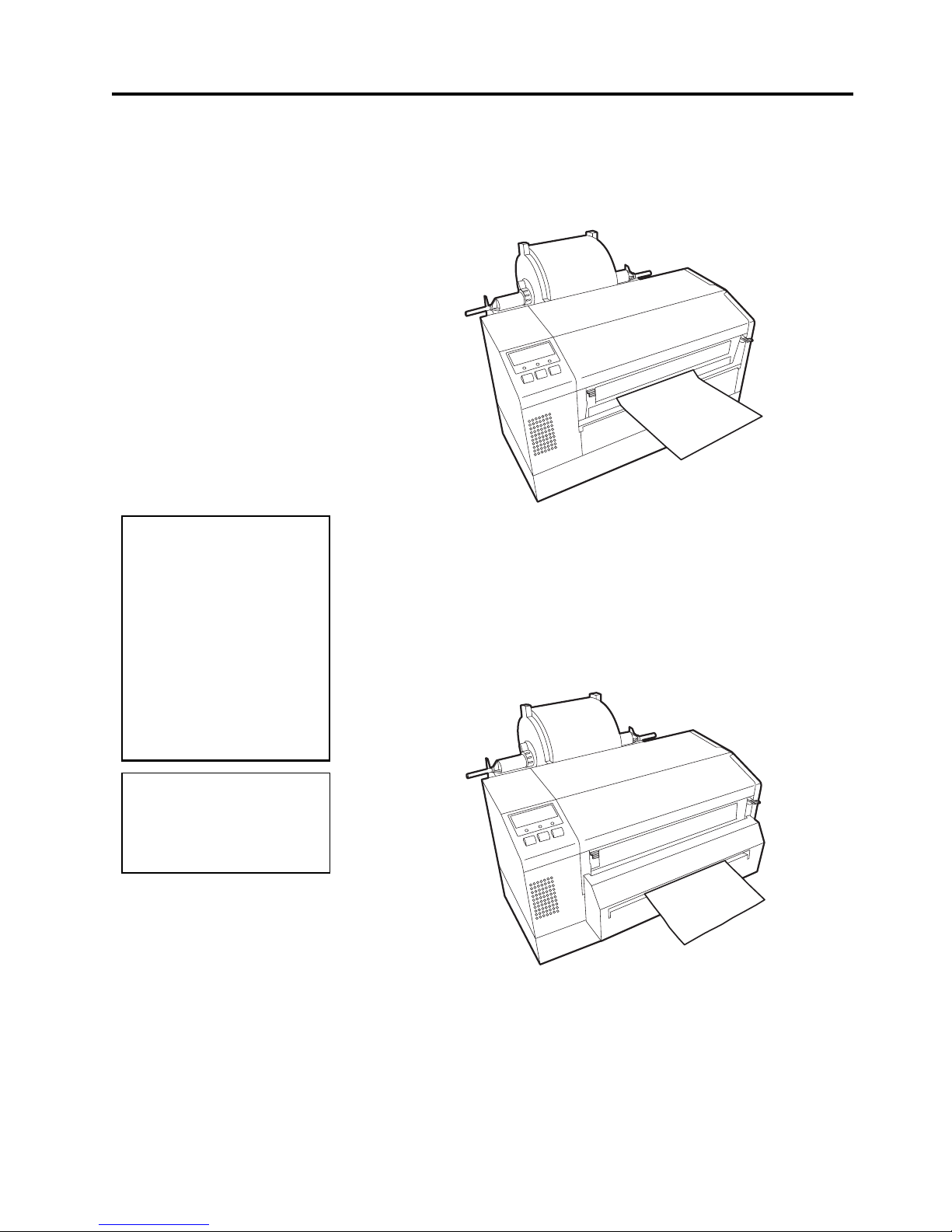
1.
Tear Off Mode – In this operation mode, when the media has stopped
feeding after printing, the label should be in a position that the
operator can simply pull the media downward against the tear off bar
to tear off the printed label.
3. PRINTER OPERATION
EO1-33029
3.2 Operating Modes
3- 2
3.2 Operating Modes
(Cont.)
2.
Continuous (or batch) mode – In this mode, the labels will be
continuously printed and fed until the number of labels specified in
the label issue command has been printed. After the last label of the
series has been printed the labels can be torn free from the supply roll
in a similar manner as described in the tear off mode above.
3.
Cut Mode - In the cut mode, as each label is printed it is fed forward
to the cutter mechanism where the swing cutter mechanism will
precisely cut the label off from the supply roll. The feed mechanism
will then backfeed the label or card stock until it is properly positioned
under the print head to print the next label in series. The issue
command sent to the printer from the Host can inform the printer to
cut each label or tag after each has been printed or to perform the cut
only after a certain number of labels or tags have been printed and
issued.
CAUTION!
•
Be sure to cut the
backing paper of label.
Cutting labels will cause
the glue to stick to the
cutter, which may affect
the cutter quality and
shorten the cutter life.
•
Use of tag paper when
the thickness exceeds
the specified value may
affect the cutter life.
NOTE:
Cut mode is available only when
the optional cutter module
(B-7208-QM) is installed.
3. PRINTER OPERATION
EO1-33029
3.3 Installing the Print er Dri vers
3- 3
3.3 Installing the Printer
Drivers
3.3.1 System Requirements
3.3.2 Driver Download
The TEC MONO Printer Dr iver is a fil e of driver inf ormation files to be
used to install TEC monochrome thermal printers to operate under
Windows 95
®,
Windows 98
®,
and
Windows NT®.
Installation is accomplished by first downloading the set of printer driver
files from the TOSHIBA TEC Web Site and transferring the printer
drivers to the hard drive of your host computer. Then using the standard
Windows Add Printer function, the driver for the B-852 will be installed.
Once the driver has been installed, then it becomes quite easy to select
the printer properties dialog and set the parameters for printing.
1.
System
a. IBM Compatible PC running Windows 95® or Windows 98® or
Windows NT® Version 4.0 Workstation or Windows NT®
Version 4.0 Server.
b. Pentium® processor, 133MHz or greater recommended.
c. Installed memory of 16MB minimum (32MB recommended).
d. Available Hard Disk space of 10MB or more.
2.
Interface
a. The RS-232C interface
b. Centronics interface
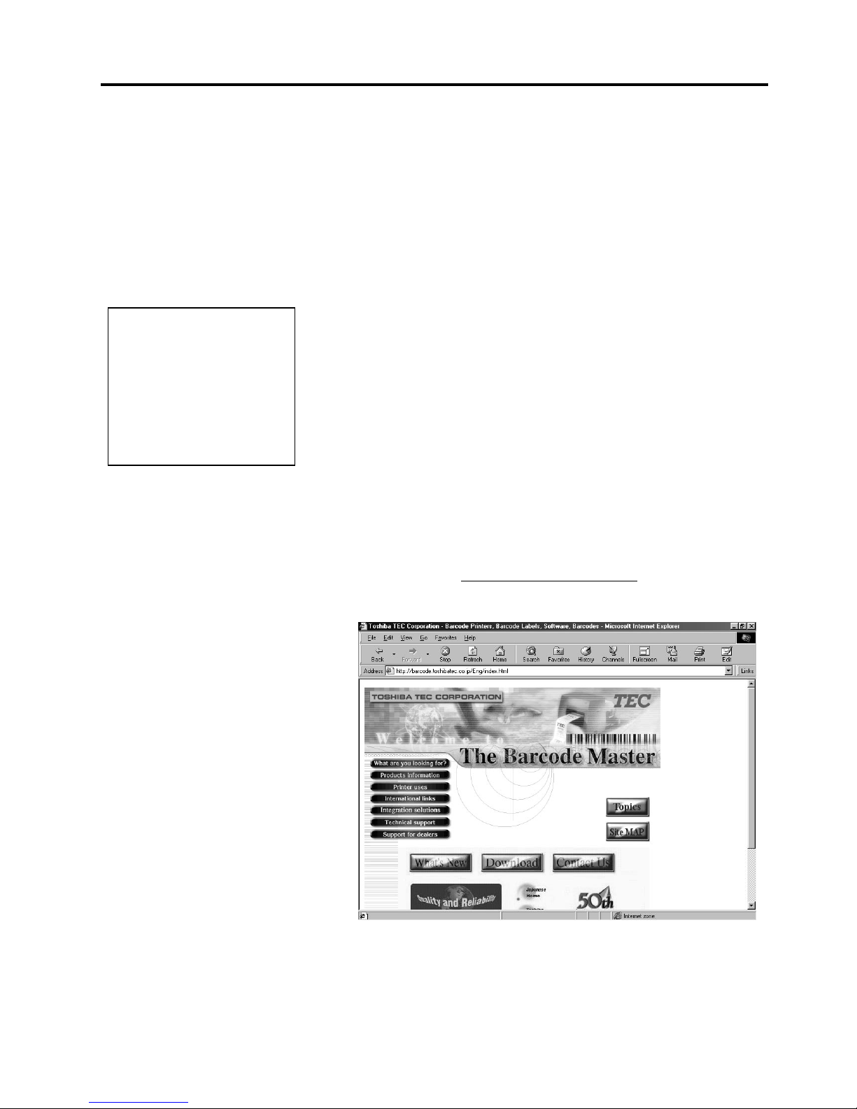
The following procedures will show you how to obtain the set of TEC
MONO Printer Drivers from the TOSHIBA TEC Barcode Web Site.
1.
Access the TOSHIBA TEC Barcode World Wide Web Site at the
following URL:
http://barcode.toshibatec.co.jp
After accessing the above web site, the screen will appear as shown below.
NOTE:
Windows 3.1® is not supported.
Windows 3.1®, Windows 95®,
Windows 98®, and Windows
NT®
are registered trademarks
of Microsoft Corporation.
Pentium® is a registered trademark of Intel Corporation
 Loading...