

Toshiba TEC B-570 Series Maintenance Manual

TEC Thermal Printer
B-570 SERIES
Original Nov., 1993
(Revision Apr., 1994)
PRINTED IN JAPAN
Maintenance Manual
Document No. EM18-33010A

EM18-33010A
TABLE OF CONTENTS
1. UNPACKING ...................................................................................................... 1- 1
1.1 Procedures .................................................................................................. 1- 1
1.2 Checks ........................................................................................................ 1- 1
2. MAJOR UNIT REPLACEMENT.......................................................................... 2- 1
2.1 REPLACING THE PS UNIT, I/F PC BOARD AND CPU PC BOARD ......... 2- 2
2.2 REPLACING THE STEPPING MOTOR...................................................... 2- 4
2.3 REPLACING THE RIBBON MOTORS........................................................ 2- 5
2.4 REPLACING THE TAKE-UP MOTOR ........................................................ 2- 5
2.5 REPLACING THE SOLENOID.................................................................... 2- 7
2.6 REPLACING THE PRINT HEAD ................................................................ 2- 8
2.7 REPLACING THE PLATEN AND FEED ROLLER..................................... 2-11
2.8 REPLACING THE PAPER SENSOR ......................................................... 2-13
2.9 REPLACING THE RIBBON BACK TENSION BLOCK .............................. 2-13
2.10REPLACING THE PINCH ROLLER SHAFT ASS’Y .................................. 2-14
2.11CORRECTING SKEW PRINTING ............................................................. 2-16
3. INSTALLATION PROCEDURE FOR THE OPTIONAL EQUIPMENT................ 3- 1
3.1 HIGH SPEED PC INTERFACE BOARD (B-4800-PC-QM)......................... 3- 1
3.2 CUTTER MODULE (B-4205-QM) ............................................................... 3- 3
3.3 MEMORY MODULE.................................................................................... 3- 5
3.4 FANFOLD PAPER GUIDE MODULE (B-4905-FF-QM) .............................. 3- 7
4. MECHANISM DESCRIPTIONS.......................................................................... 4- 1
4.1 CUTTER DRIVE (CUT MODE) ................................................................... 4- 1
4.2 HARNESS WIRING .................................................................................... 4- 2
5. TROUBLESHOOTING........................................................................................5- 1
6. DIAG. TEST OPERATION..................................................................................6- 1
7. PROGRAM DOWN LOAD .................................................................................. 7- 1
7.1 FLOPPY DISK............................................................................................. 7- 1
7.2 SETUP ........................................................................................................ 7- 1
7.3 DOWN LOAD PROCEDURE ...................................................................... 7- 2
7.4 ERROR CODE ............................................................................................ 7- 3
(Revision Date Feb. 01 ’96)
Page
CAUTION:
1. This manual may not be copied in whole or in part without prior written permission of
TOSHIBA TEC.
2. The contents of this manual may be changed without notification.
3. Please refer to your local Authorized Service representative with regard to any queries you
may have in this manual.
Copyright © 1999
by TOSHIBA TEC CORPORATION
All Rights Reserved
570 Ohito, Ohito-cho, Tagata-gun, Shizuoka-ken, JAPAN
1-1
EM18-33010A
1. UNPACKING
1.2 CHECKS
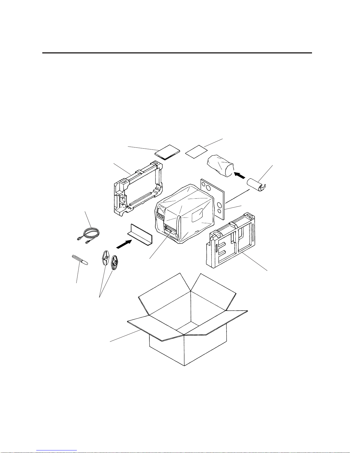
1) Check for any damage or scratches on the machine.
2) Confirm that none of the accessories are missing.
NOTE: Keep the carton and side pads for later transport.
Carton
Thermal Printer
Side Pad (L)
Power Cord
Owner’s Manual
Side Pad (R)
Fig. 1-1
1. UNPACKING
1.1 PROCEDURE
1) Open the carton.
2) Unpack the accessories from the carton.
3) Unpack the side pad (L)/(R) and the printer from the carton.
4) Place the printer on a level surface.
(Revision Date Sep. 14 ’95)
1.1 Procedure
Supply
Holder
Head Cleaner
Unpacking
Procedure
Rewinder
Guide Plate
Rear Pad
2-1
EM18-33010A
2. MAJOR UNIT REPLACEMENT
CAUTION: 1) Lubrication: During parts replacement
2) Kinds of oil: FLOIL G-488: 1 Kg can. (Part No. 19454906001).
NOTE: Instructions to remove the top cover and left side cover are omitted from each removal/
installation procedure provided below.
■ Lubrication
WARNING!
Disconnect power cord before replacing important parts.
Any machine is generally in its best condition when delivered; therefore, it is necessary to try to keep
this condition. Unexpected failure occurs due to lack of oil, debris or dust. To keep its best condition,
periodically clean the machine and apply proper kinds of oil to each part in which lubrication is
needed.
Although the frequency of lubrication varies according to how much the machine is used, at least it
is necessary to lubricate before the machine becomes dry. It is also necessary to wipe off excessive
oil as it collects dirt.
(Revision Date Dec. 09, ’94)
2. MAJOR UNIT REPLACEMENT
Fig. 2-1
2. MAJOR UNIT REPLACEMENT
CAUTION:
1. NEVER separate the ribbon motors from the attaching plate (bracket), because doing so will
change their adjustment. (See Fig. 2-8)
2. NEVER remove the two screws painted red on the side of the print block. (See Fig. 2-13)
3. NEVER remove the four screws on the side of the print block. (See Fig. 2-13)
4. NEVER remove the four screws painted red fixing the right plate and reinforcing plate.
(See Fig. 2-16) However, the machine with a serial number of 4T x x x x x x or later is not equipped
with the red screws because of the change in the right plate shape.
5. NEVER remove unmentioned screws because doing so will change their adjustment.
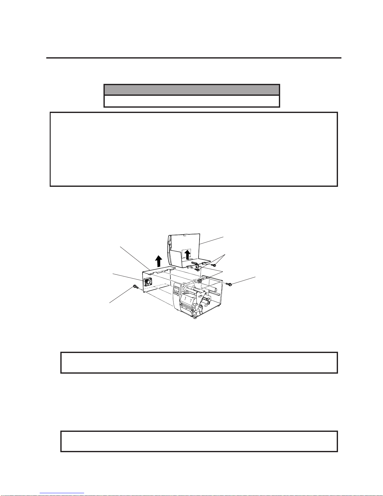
1) Turn the power off.
2) Open the top cover to remove the four FL-3x5 screws. Slide the top cover to the left to release the
damper and remove the top cover.
3) Remove the seven screws (FL-4x5 and B-4x5) to remove the left side cover.
4) Disconnect the FAN motor connector from the PS unit.
CAUTION: Do not spray the inside of the printer with lubricants. Unsuitable oil can damage
the mechanism.
Top Cover
Screw (FL-4x5)
Screw (B-4x5)
FAN Motor
Left Side Cover
Screw (FL-3x5)
Damper
2-2
EM18-33010A
2. MAJOR UNIT REPLACEMENT
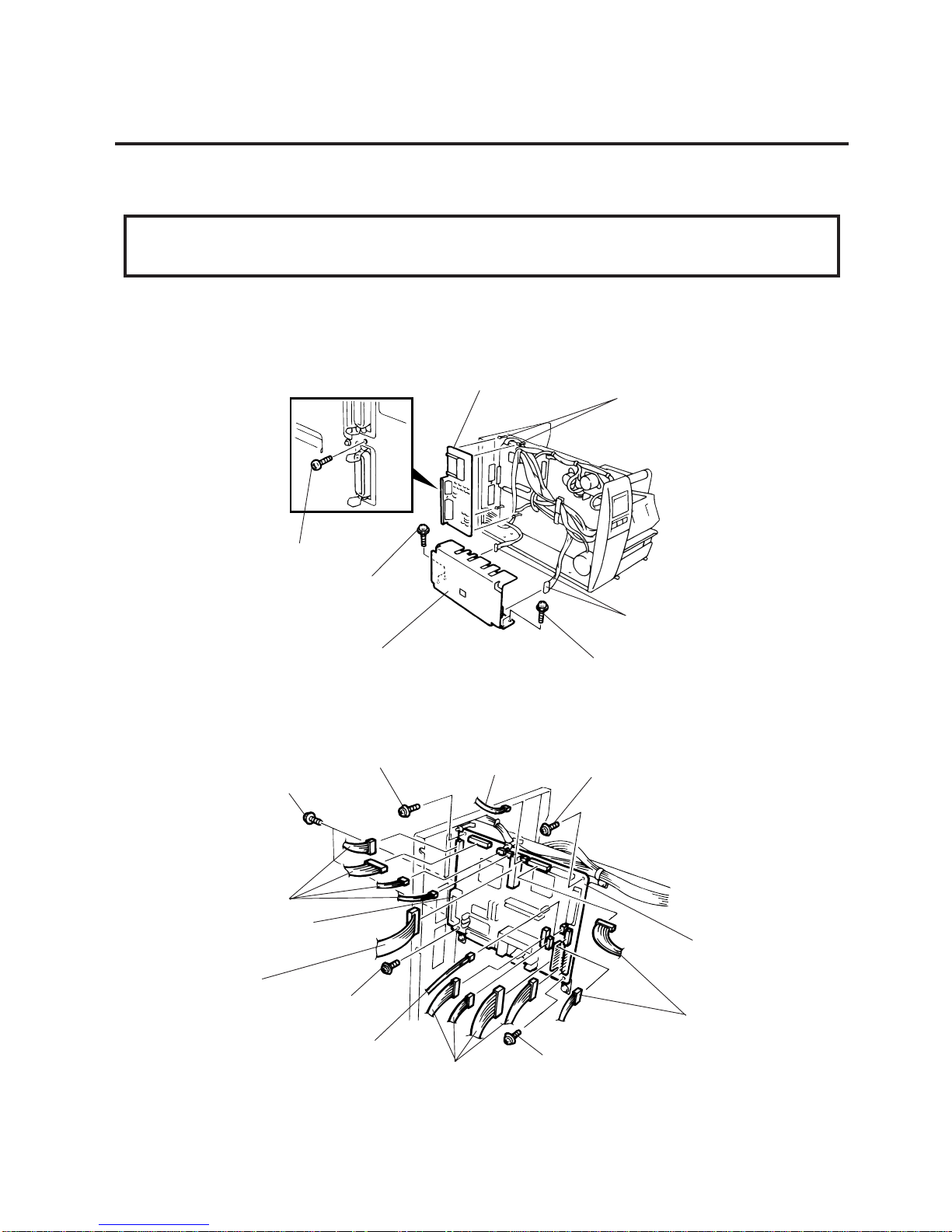
3) Disconnect the 13 connectors from the CPU PC board.
4) Remove the six screws (SM-3x6B, SM-3x6C) to detach the CPU PC board from the printer.
(Revision Date Oct. 14, ’94)
2.1 REPLACING THE PS UNIT, I/F PC BOARD AND CPU PC BOARD
2.1 REPLACING THE PS UNIT, I/F PC BOARD AND CPU PC BOARD
CAUTION:
Replace only with same type and ratings of fuse for continued protection against risk of fire.
1) Remove the three FL-4x6 screws and disconnect the two connectors to detach the PS unit.
2) Remove the FL-3x5 screw and the four locking supports to remove the I/F PC board.
Fig. 2-2
5) Replace the PS unit, I/F PC board and CPU PC board. Insert the connectors correctly and install
in the reverse order of removal above. Do not mount the left side cover and top cover.
Fig. 2-3
PS Unit
Screw (FL-4x6)
Screw (FL-3x5)
I/F PC Board
Screw (FL-4x6)
Connector
Locking Support
Screw (SM-3x6B)
Screw (SM-3x6B)
CPU PC Board
Connector
Connector
Connector
Screw (SM-3x6B)
Connector
Connector
I/F Connector
Screw (SM-3x6C)
Screw (SM-3x6B)
Connector
2-3
EM18-33010A
2. MAJOR UNIT REPLACEMENT
CAUTION:
Be careful when replacing the CPU PC board, since a non-resettable counter (IC12) is installed on
this board. (Refer to Section 6.2.1 Maintenance Counter Printing.)
If this counter should be reset, replace IC12.
Fig. 2-4
Fig. 2-5
2.1 REPLACING THE PS UNIT, I/F PC BOARD AND CPU PC BOARD
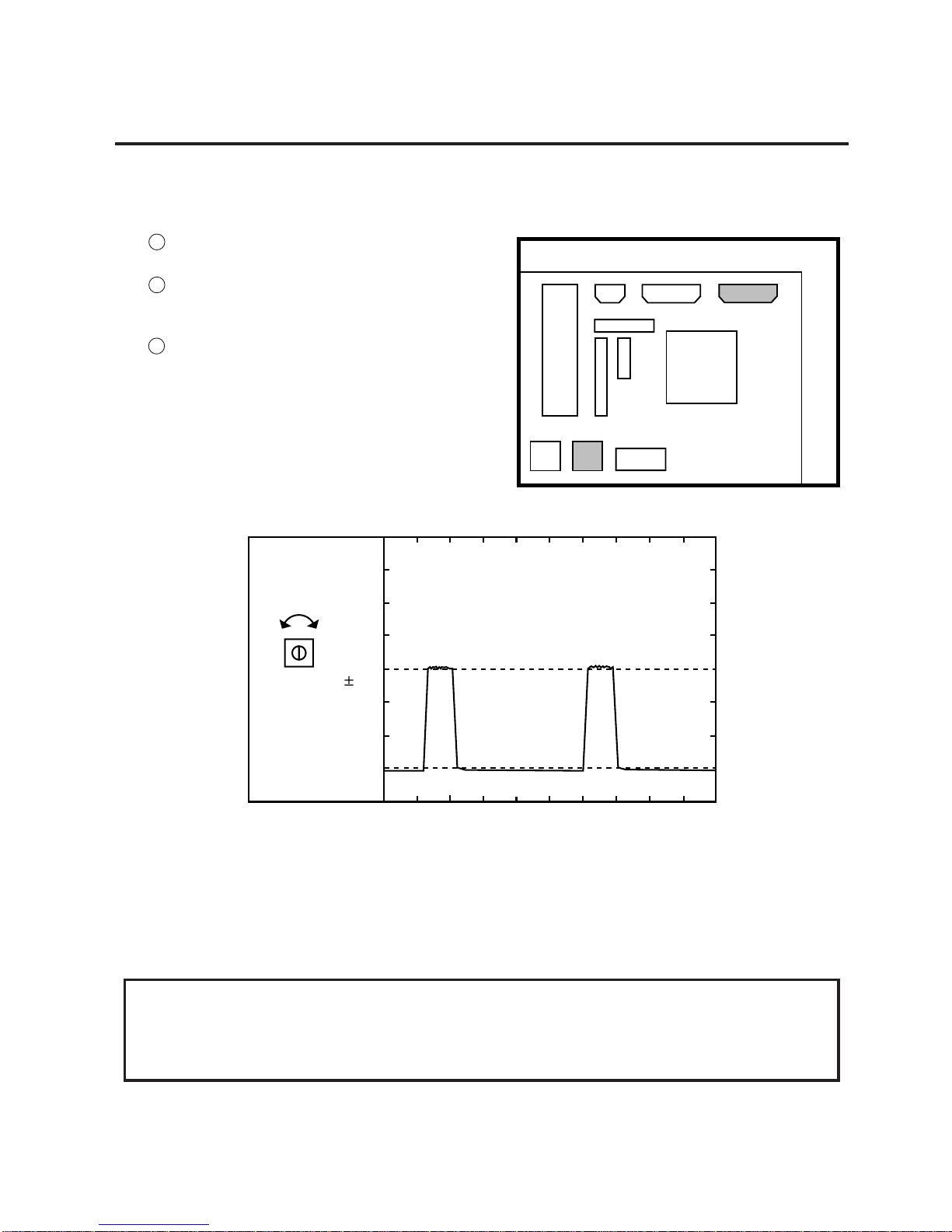
6) Adjust the ribbon end sensor.
Use the following Ribbons; TTM-78 (Maker: Fujicopian)
1 Set the ribbon so that the ribbon end sensor
can detect the ribbon. Turn the power on.
2 Turn the VR2 so that the voltage between Pin
1 (GND) and Pin 7 of CN10 is 3.0 ± 0.2 V with
an oscilloscope.
3 Turn the power off and mount the left side
cover and top cover.
7) Adjust the black mark sensor.
As the black mark sensor is adjusted by key entries in system mode, refer to page 6-39 for the
adjustment procedure.
8) Adjust the feed gap sensor.
As the feed gap sensor is adjusted by key entries in system mode, refer to page 6-40 for the
adjustment procedure.
CN7
CN8
RA9
CN9
RA10
RA11
VR1 VR2
IC30
IC16
110
CN10
Range : 1V / 0.2 m sec.
Voltage
3.0
0.2V
VR2
GND
2-4
EM18-33010A
2. MAJOR UNIT REPLACEMENT
4) When replacing the stepping motor, place the platen belt first then the feed roller belt around the
pinion gear so that the partition is positioned between two belts. Hold down the stepping motor at
3.5 kg ± 300 g force and secure it so that the belts have no slack or disengagament.
5) Reassemble in the reverse order of removal.
Fig. 2-6
2.2 REPLACING THE STEPPING MOTOR
2.2 REPLACING THE STEPPING MOTOR
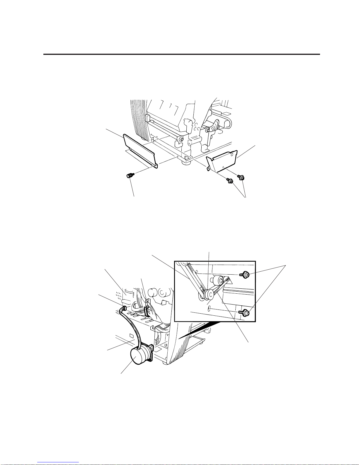
1) Remove the two black screws to detach the front plate, remove the two FL-4x6 screws to detach the
belt cover.
2) Unclamp and disconnect the connector from CN14 on the CPU PC board.
3) Remove the two SM-4x8B screws, loosen the two belts from the pinion gear, and remove the
stepping motor.
Fig. 2-7
Black Screw
Front Plate
Belt Cover
Screw (FL-4x6)
CPU PC Board
CN14
PS Unit
Stepping Motor
Clamp
Partition
Pinion Gear
Feed Roller Belt
Screw (SM-4x8B)
Platen Belt
2-5
EM18-33010A
2. MAJOR UNIT REPLACEMENT
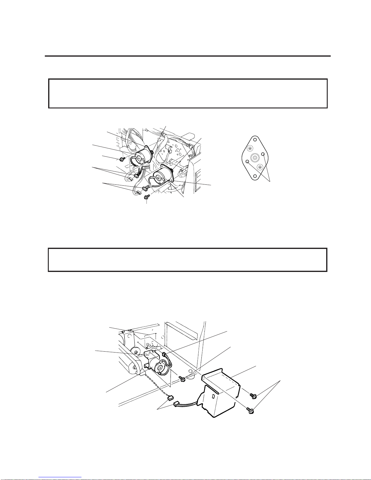
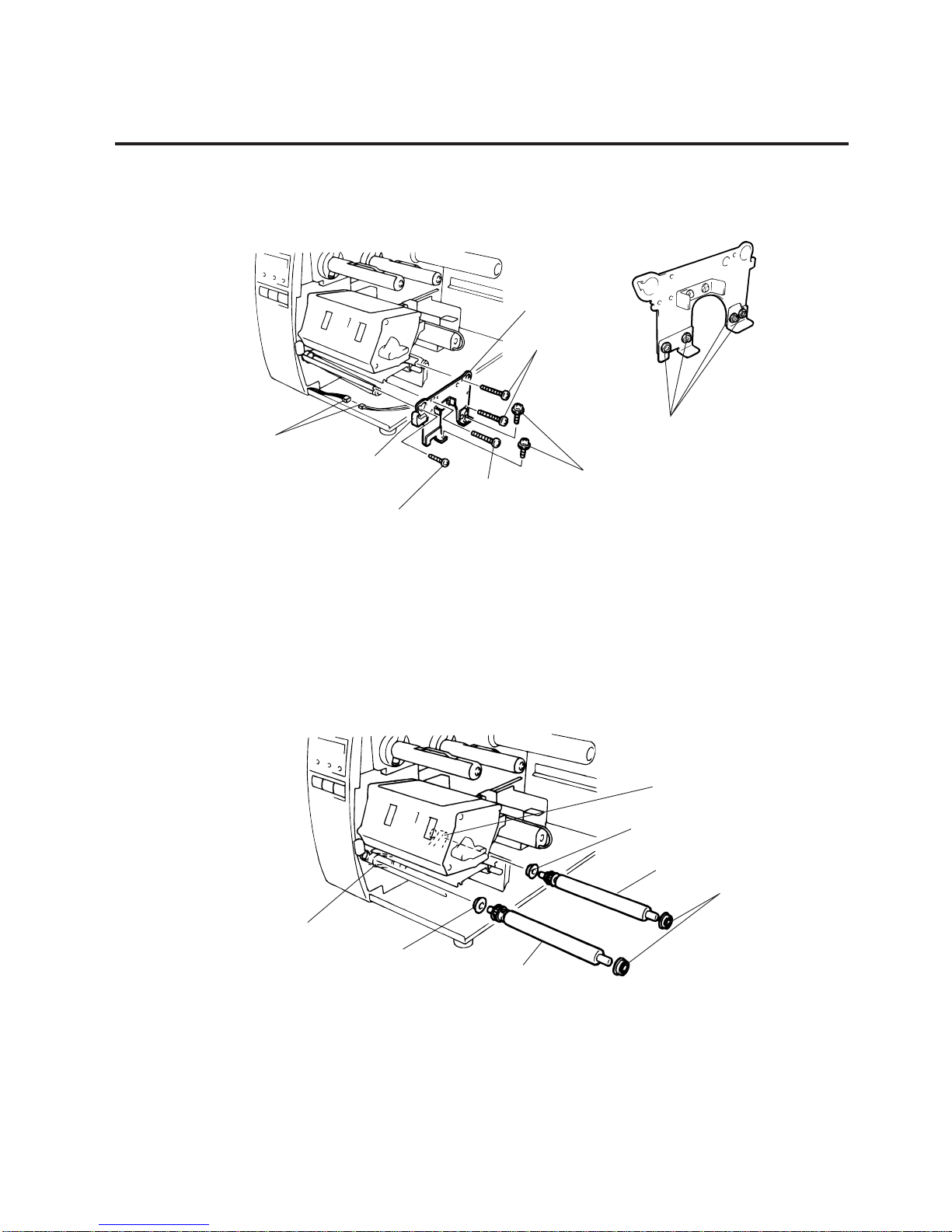
2) Replace the ribbon motors, then align the dowels to attach the ribbon motors. Reassemble in the
reverse order of removal.
2.4 REPLACING THE TAKE-UP MOTOR
NOTE: The following procedure can be employed without removing the top cover and left side cover.
1) Remove the four FL-3x5 screws to detach the motor cover.
2) Remove the connector for the rewind full sensor (LED).
3) Disconnect the connector from the CN1 on the PWM PC board and remove the two FL-3x5 screws
to detach the take-up motor.
Fig. 2-9
Fig. 2-8
2.3 REPLACING THE RIBBON MORTORS
2.3 REPLACING THE RIBBON MOTORS
CAUTION:
NEVER separate the ribbon motors from the attaching plate because doing so will change their
adjustment.
1) Disconnect the connector and remove the two SM-3x5B screws to detach the ribbon motors.
CAUTION:
NEVER separate the take-up motor from the bracket because doing so will change the adjustment.
4) Replace the take-up motor, then align the dowels to attach the motor cover and rewind full sensor
(Tr).
Dowels
FLOIL G-488
Attaching Plate
Ribbon Motor
Screw (SM-3x5B)
Connector (Black)
Connector (Red)
Screw (SM-3x5B)
Ribbon Motor
Attaching Plate
FLOIL G-488
Connector (CN1)
Screw (FL-3x5)
Motor Cover
Screw (FL-3x5)
Connector
Take-up Motor
Bracket
PWM PC Board
FLOIL
2-6
EM18-33010A
2. MAJOR UNIT REPLACEMENT
Fig. 2-10
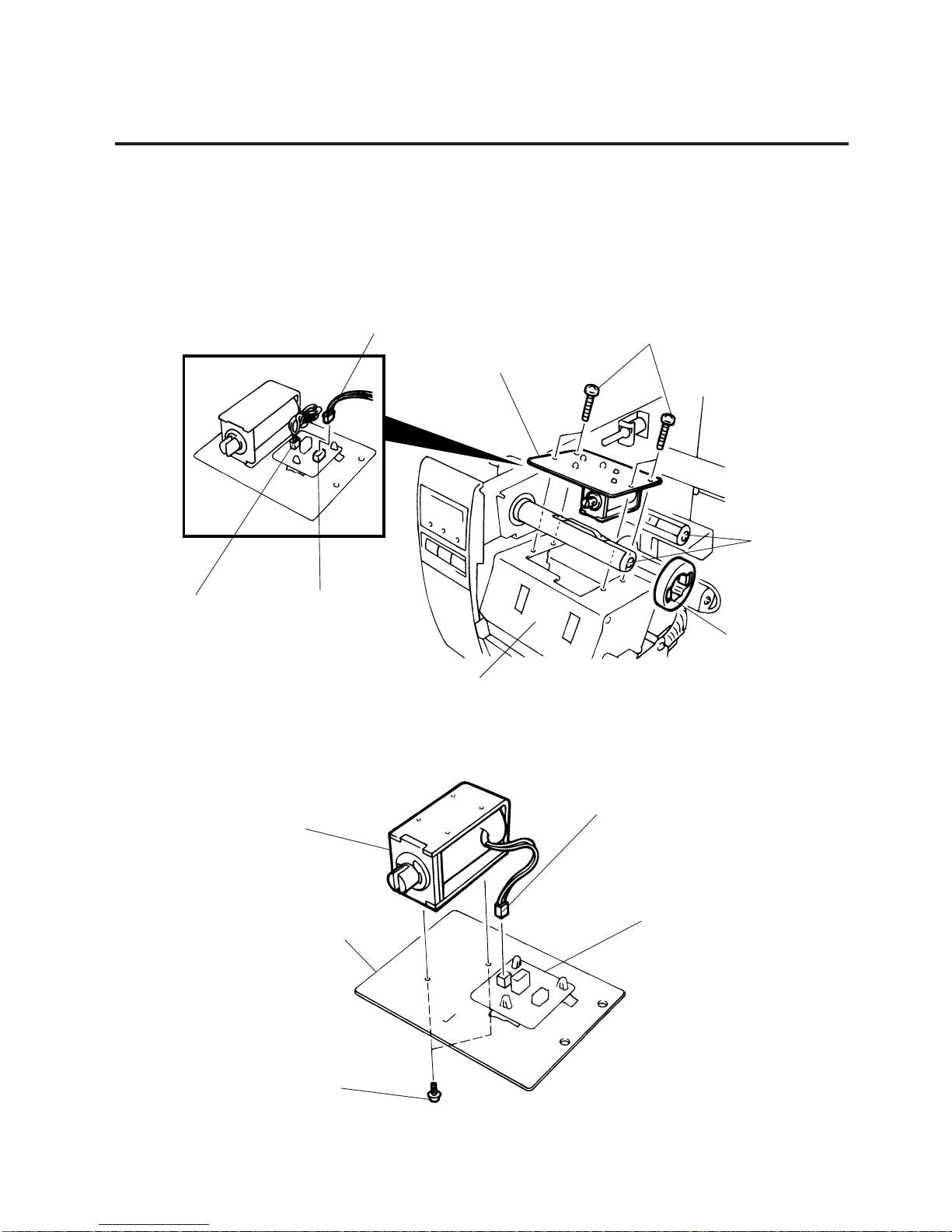
2.5 REPLACING THE SOLENOID
2.5 REPLACING THE SOLENOID
NOTE: The following procedure can be employed without removing the top cover and left side cover.
1) Before removing the ribbon stopper, check its attaching direction for later installation. Remove the
ribbon stopper from the ribbon shaft on which the ribbon is wound.
2) Remove the two SM-4x8B screws, disconnect the connector CN1 on the RSV PC board to detach
the solenoid unit.
3) Remove the two SM-3x5B screws and disconnect the CN2 connector on the RSV PC board to detach
the solenoid.
Fig. 2-11
Ribbon Shaft
Ribbon Stopper
Print Block
RSV PC Board
CN2 (2 pin)
Connector CN1 (3 pin)
Solenoid Attaching Plate
Screw (SM-4x8B)
Solenoid
Connector CN2 (2 pin)
RSV PC Board
Screw (SM-3x5B)
Solenoid Attaching Plate
2-7
EM18-33010A
2. MAJOR UNIT REPLACEMENT
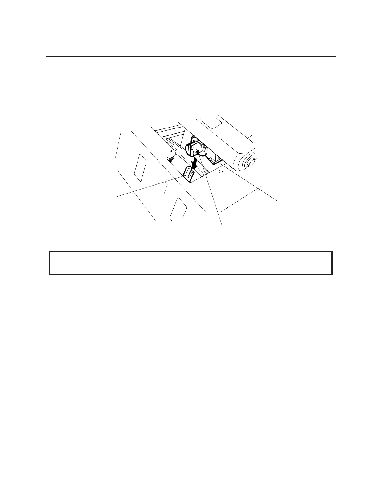
2.5 REPLACING THE SOLENOID
NOTE: Make sure to remove any dust that appears during removal or installation because it may affect
the print quality.
4) Replace the solenoid and attach it to the solenoid attaching plate.
5) Assemble the solenoid unit so that the head up link engages the spring pin.
Fig. 2-12
CAUTION:
Take care to orient the screws so that they are vertically aligned with the solenoid attaching plate.
6) Reassemble in the reverse order of removal.
Head Up Link
Spring Pin
Solenoid
2-8
EM18-33010A
2. MAJOR UNIT REPLACEMENT
Fig. 2-13
(Revision Date Feb. 01, ’96)
2.6 REPLACING THE PRINT HEAD
2.6 REPLACING THE PRINT HEAD
CAUTION:
1. NEVER touch the element when handling the print head.
2. NEVER touch the connector pins to avoid a breakdown of the print head by static electricity.
3. NEVER remove the two screws painted red on the side of the print block.
4. NEVER remove the four screws on the side of the print block.
5. NEVER remove the print block, otherwise it requires the adjustment of the position when
reassembling.
NOTE: The following procedure can be employed without removing the top cover and the left side cover.
2.6.1 Old type print head
1) Turn the head lever clockwise to lower the print head. Remove the two SM-4x8B screws.
2) Turn the head lever counter clockwise and disconnect the two connectors to detach the print
head from the print block.
3) Replace the print head, connect the connectors and install it in the print block.
4) Turn the head lever clockwise. Push the print head and secure it temporarily.
Follow the procedure on the next page.
Screw (SM-4x8B)
Screws
(NEVER remove these screws.)
Screws painted red
(NEVER remove these screws.)
Connector
Print Block
Print Head
Connector
Head Lever
2-9
EM18-33010A
2. MAJOR UNIT REPLACEMENT
Strip Shaft
Fig. 2-14
(Revision Date Feb. 01, ’96)
2.6 REPLACING THE PRINT HEAD
■ Adjusting the print head position
1 Fit the jig in the platen and strip shaft.
2 Press the jig at an angle of 45° until it is sung against the print head. Then secure the print head.
3 Remove the jig.
4 Refer to page 6-43 and clear the maintenance counter.
5 Refer to page 6-31 and perform test print.
NOTE: Use caution to prevent damage to the element during adjustment of the print head.
Platen
Ceramic
Print Head
Platen
Strip Shaft
Jig
2-10
EM18-33010A
2. MAJOR UNIT REPLACEMENT
Fig. 2-15
2.6.2 New type print head
1) Turn the head lever clockwise to lower the print head. Remove the two SM-4x8B screws.
2) Turn the head lever counterclockwise and disconnect the two connectors to detach the print
head from the print block.
(Revision Date Feb. 01, ’96)
2.6 REPLACING THE PRINT HEAD
NOTE:NEVER loosen screws other than two SM-4x8B.
3) Replace the print head and connect the connectors.
4) Align the two holes A in the middle of the print head with the print head position adjusting pins
provided in the print block and fit the print head into the print block.
5) Turn the head lever clockwise and secure the print head with screws in the holes B .
■ Adjusting the print head position
When print tone becomes light from using special paper with improper print head position, please
follow the procedure below and adjust the print head position.
NOTE:
Never loosen screws C unless print position fine adjustment is required because they have been
adjusted properly. Doing so will change the adjustment.
Screw (SM-4x8B)
Screws
(NEVER remove these screws.)
Screws painted red
(NEVER remove these screws.)
Connector
Print Block
A
Connector
B
B
Print Head
2-11
EM18-33010A
2. MAJOR UNIT REPLACEMENT
Fig. 2-17
2.6 REPLACING THE PRINT HEAD
2.7 REPLACING THE PLATEN AND FEED ROLLER
1) Remove the front plate and belt cover. (See Fig. 2-6.)
2) Turn the head lever counterclockwise, then release the ribbon shaft holder plate.
Fig. 2-16
(1) Loosen the screws c securing the print head position adjusting pin.
(2) Loosen the screws b one by one, slightly move the print head backward or forward, and then
tighten the screws b and c . Ensure that the print head is parallel to the platen. If not, print
tone will be uneven.
(3) Make a test print and if necessary, repeat Step 2) until the printer prints properly.
CAUTION:
1. NEVER remove the four screws painted red fixing the right plate and reinforcing plate.
(See Fig. 2-16)
2. The pinch roller belt assembled inside the printer does not need to be replaced because it
receives less load.
Print Head Bracket
Print Head
b (securing the print head)
c (securing the adjusting pin)
A
(Print Head Position
Adjusting Pin)
cb
E-ring (M3)
Hold Shaft
Ribbon Shaft Holder Plate
Head Lever
2-12
EM18-33010A
2. MAJOR UNIT REPLACEMENT
3) Disconnect the connector for the strip sensor (LED).
4) Remove the six screws (FL-4x6, B-4x12 and P-3x12) to detach the right plate ass’y.
NOTE: The machine with a serial number of 4T x x x x x x or later is not equipped with the red screws
because of the change in the right plate shape.
5) Loosen the two screws (SM-4x8B) fixing the stepping motor to loosen the platen belt and feed roller
belt.
6) Remove the platen belt to detach the platen. Remove the feed roller belt to detach the feed roller.
7) Remove both bearings from the platen or feed roller.
8) Replace the platen and feed roller, put on the belt and assemble it with the printer. The longer belt
is the platen belt.
9) Attach the right plate.
10) Hold down the stepping motor and secure it so that the belts have no slack or disengagement.
11) Reassemble in the reverse order of removal.
Fig. 2-18
Fig. 2-19
(Revision Date Sep. 29, ‘95)
2.7 REPLACING THE PLATEN AND FEED ROLLER
Connector
Strip Sensor (LED)
Screw (P-3x12)
Screw (B-4x12)
Right Plate
Screw (B-4x12)
Screw (FL-4x6)
Screws painted red
(NEVER remove these screws.)
Feed Roller Belt
Holder
Feed Roller (Gray)
Holder
Platen (Black)
Holder
Platen Belt
2-13
EM18-33010A
2. MAJOR UNIT REPLACEMENT
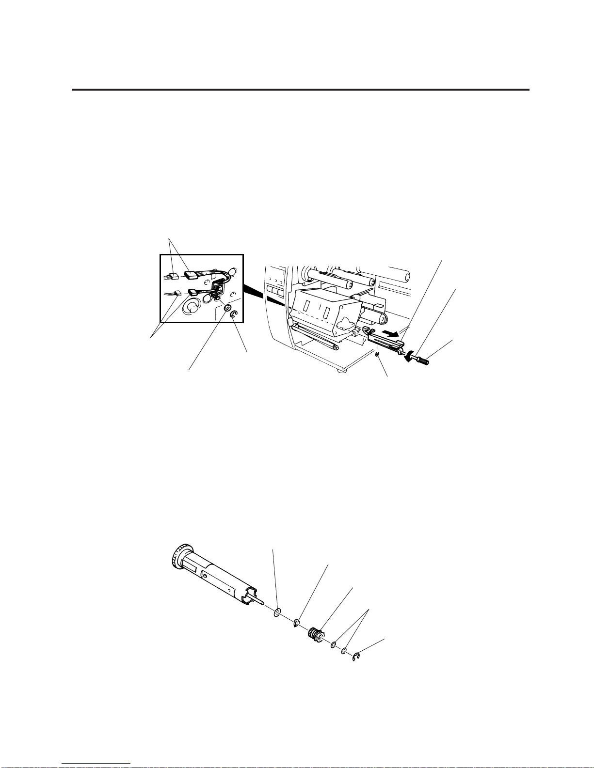
5) Replace the paper sensor and reassemble in the reverse order of removal.
6) After replacing the paper sensor, refer to page 6-32/6-33 and adjust the voltage.
2.9 REPLACING THE RIBBON BACK TENSION BLOCK
1) Turn the head lever counterclockwise, then release the ribbon shaft holder plate.
2) Remove the M3 E-ring and the two M3 washers to remove the ribbon back tension block. At this time,
remove the back tension stopper and ribbon back tension washer from the ribbon back tension block.
Fig. 2-20
Fig. 2-21
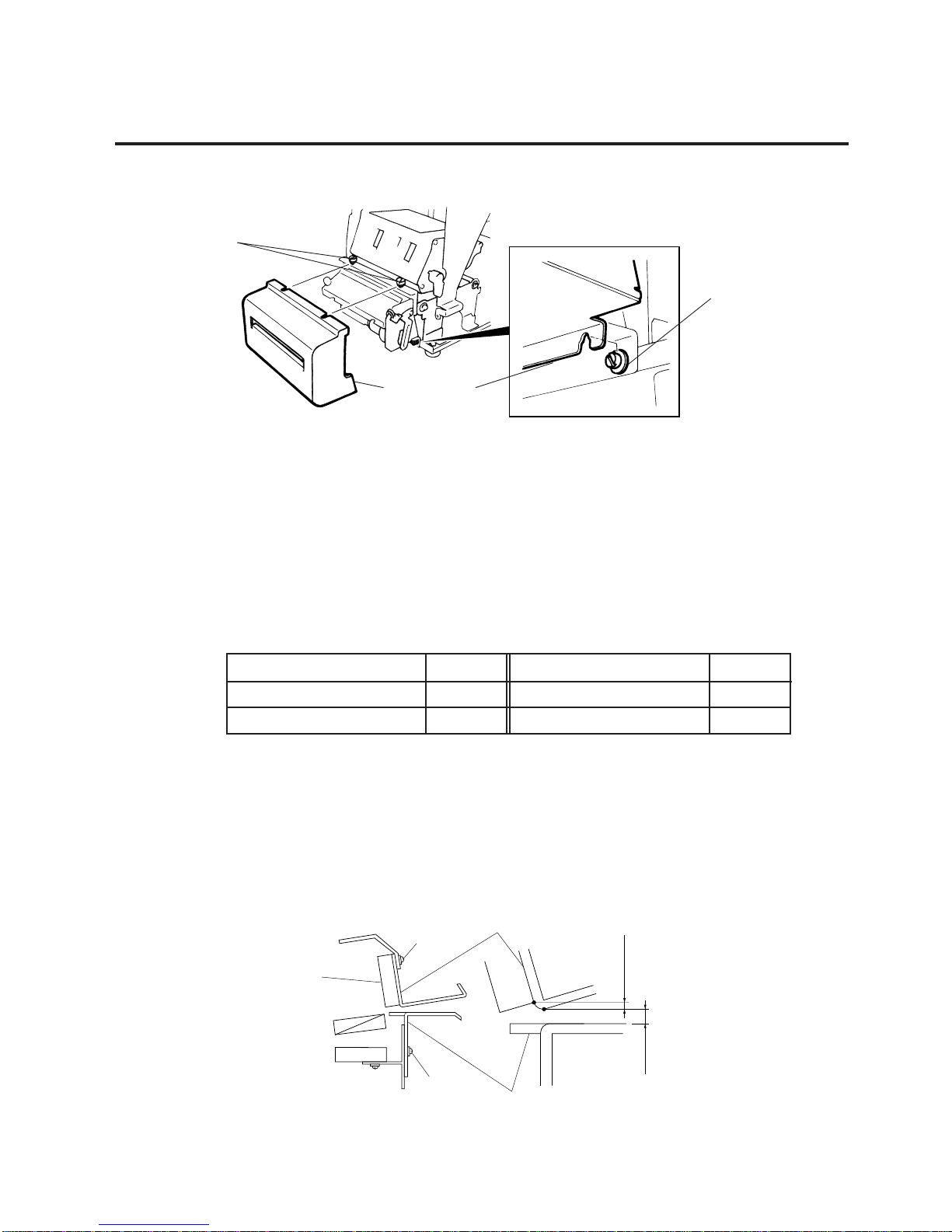
2.8 REPLACING THE PAPER SENSOR
2.8 REPLACING THE PAPER SENSOR
NOTE: Turn the knob until the paper sensor reaches full forward.
1) Disconnent the connector for the strip sensor (LED) to remove right plate ass’y.
(See Figs. 2-17 and 2-18.)
2) Disconnect the connectors for the paper sensor.
3) Remove M1.5 E-ring, M3 washer and paper sensor unit.
4) Remove M1.5 E-ring, turn the knob counter clockwise, then remove the paper sensor.
3) Replace the back tension block and reassemble in the reverse order of removal.
Paper Sensor
Sensor Shaft
Knob
E-ring (M3)
E-ring (M3)
Washer (M3)
Connector (2 pin)
Connector (4 pin)
Ribbon Back Tension Washer
Back Tension Stopper
Ribbon Back Tension Block
E-ring (M3)
Washer (M3)
2-14
EM18-33010A
2. MAJOR UNIT REPLACEMENT
(Revision Date Sep. 29, ’95)
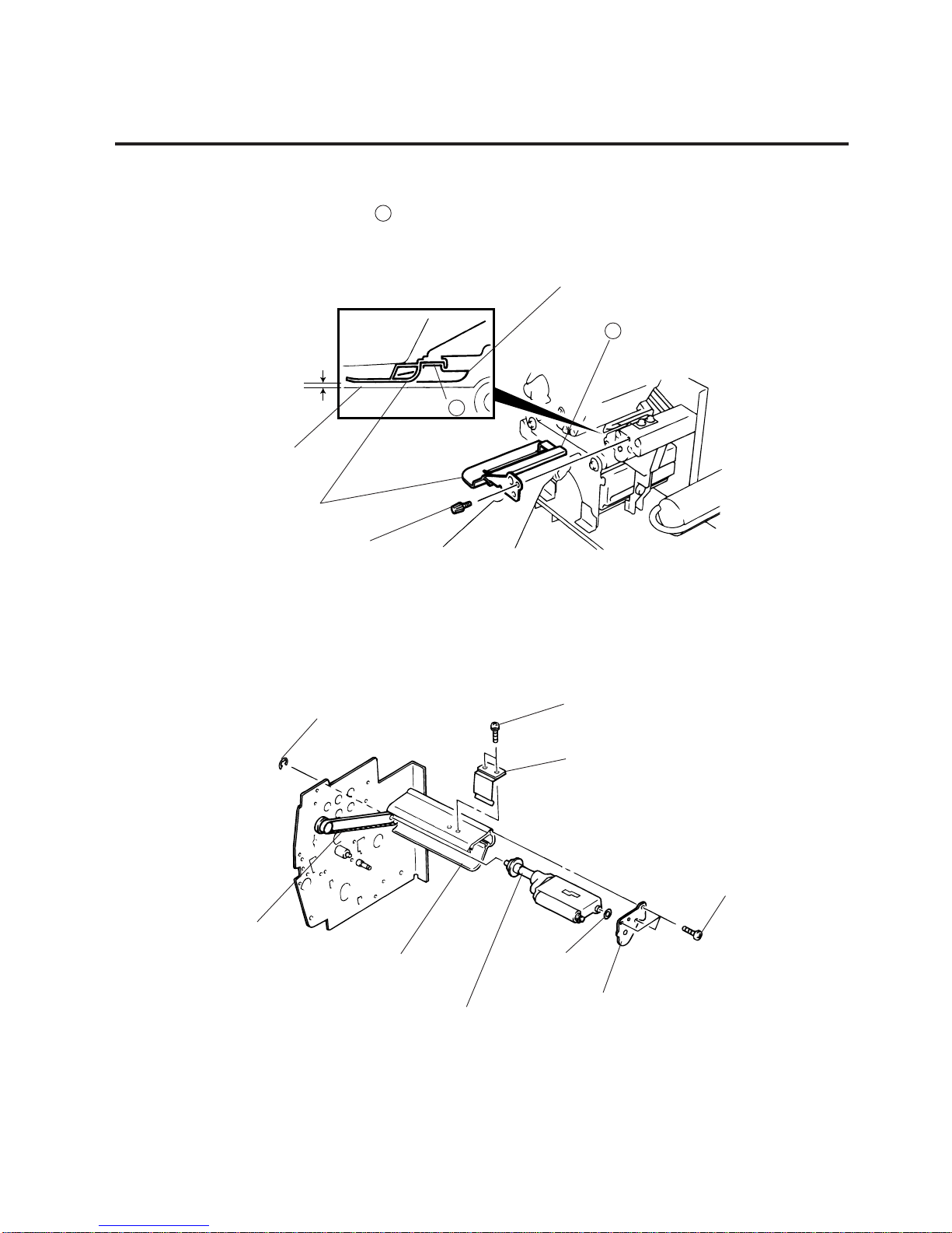
2.10 REPLACING THE PINCH ROLLER SHAFT ASS’Y
2.10 REPLACING THE PINCH ROLLER SHAFT ASS’Y
1) Turn the head lever to position 3 , and release the ribbon shaft holder plate.
2) Remove the black screw to detach the media guide plate.
3) Remove the SM-4x8B screw to detach the spring plate.
4) Remove the six B-4x12 screws to detach the pinch roller cover.
5) Remove the E-5 E-ring to loosen the pinch roller belt, and remove the pinch roller shaft ass’y.
6) After replacing the pinch roller shaft ass’y, make the following adjustment while you reassemble the
pinch roller shaft ass’y in the reverse order of removal.
Fig. 2-22
Fig. 2-23
B
Media Sensor
Black Screw
(HAA-0004001)
B
Media Guide Plate
Printer Block Base
1.5 mm~2.5 mm
SM-4x8B
Spring Plate
B-4x12
E-5
Pinch Roller Belt
Pinch Roller Cover
Pinch Roller Shaft Ass’y
W-8
Pinch Roller Cover
2-15
EM18-33010A
2. MAJOR UNIT REPLACEMENT
(Revision Date Sep. 29, ’95)
2.10 REPLACING THE PINCH ROLLER SHAFT ASS’Y
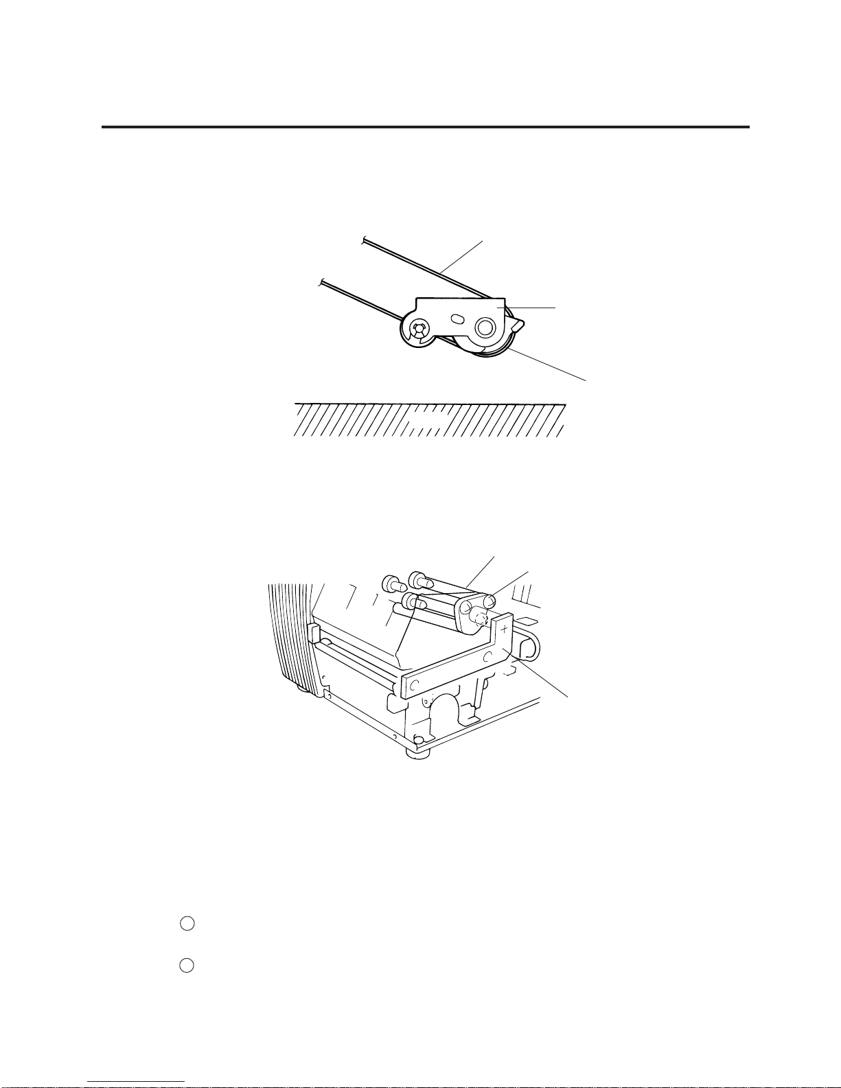
■ Adjustment
1. Install the pinch roller unit so it parallels the base. If it does not, change the engaging position of the
pinch roller belt and the pulley.
Fig. 2-24
Fig. 2-25
2. Attach the jig to the platen, feed roller and pinch roller shaft as shown in the figure below.
Then attach the pinch roller cover to the pinch roller frame with the three B-4x12 screws.
Then secure the pinch roller frame with the three B-4x12 screws.
NOTES:1. Replace the platen and the feed roller prior to attaching the jig.
2. Attach the jig while the pinch roller frame is tentatively attached to the main frame with the
B-4x12 screws. Secure the pinch roller cover to the pinch roller frame with the three B-4x12
screws, then tighten the other side of the screws.
3. The flat top of the pinch roller frame must be installed in parallel to bosses on the printer
frame.
Check
1 Check if excessive load is applied to the jig after the above NOTE 2.
(For example, check if the pinch roller frame moves when the jig is removed.)
2 Check that there is no gap caused by a slant shaft between the pinch roller and the feed
roller when the pinch roller is lowered.
Pinch Roller Belt
Pinch Roller
Unit
Pulley
Pinch Roller Cover
B-4x12 (6 screws)
Jig
Base
2-16
EM18-33010A
2. MAJOR UNIT REPLACEMENT
Fig. 2-27
(Revision Date Sep. 29, ’95)
2.10 REPLACING THE PINCH ROLLER SHAFT ASS’Y
2.11CORRECTING SKEW PRINTING
● If media still skews after adjusting the pinch roller shaft ass’y with the jig, follow the procedure below
to correct the skew problem.
1. Check if the media skews right or left.
2. Loosen the B-4x12 screw to move the pinch roller cover to the front or rear of the printer depending
on the skew direction.
3. Turn the head lever clockwise to lock the pinch roller shaft ass’y. Attach the spring plate to the pinch
roller frame with the two SM-4x8B screws, pushing the spring plate toward the rear of the printer.
NOTE: Check that the pinch roller shaft ass’y moves up and down smoothly when turning the head
lever clockwise and counterclockwise.
4. Install the media guide plate to the printer so there is a 1.5 to 2.5 mm gap between the media guide
plate and the printer block base.
When the media skews right, move the pinch roller cover to the front.
When the media skews left, move the pinch roller cover to the rear.
● If a paper skew problem should occur when using rolls would with labels facing outside after
completing the modification, adjust the paper guide as follows.
* In case the label skews to the right side of the print head, move the guide downward.
* In case the label skews to the left side of the print head, move the guide upward.
Fig. 2-28
Fig. 2-26
Front
Rear
SM-4x8B
Pinch Roller Frame
Pinch Roller Shaft Ass’y
Spring Plate
Guide Plate

3-1
EM18-33010A
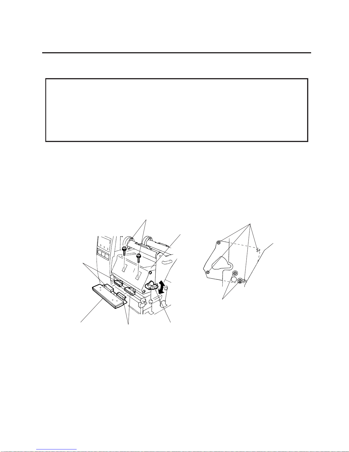
3. INSTALLATION PROCEDURE FOR THE OPTIONAL EQUIPMENT
3. INSTALLATION PROCEDURE FOR THE OPTIONAL
EQUIPMENT
3.1 HIGH SPEED PC INTERFACE BOARD (B-4800-PC-QM)
WARNING!
Make sure to unplug the power cord before installing the optional equipment.
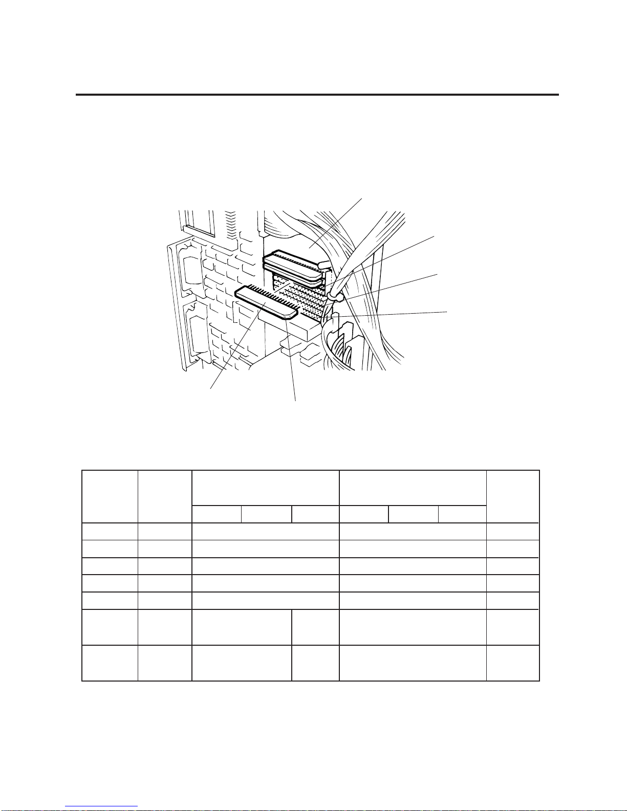
3.1 HIGH SPEED PC INTERFACE BOARD (B-4800-PC-QM)
The high speed PC interface board can be used together with the IBM PC-AT or its compatible machine
only.
1. Remove the top cover and left side cover. (See Fig. 2-1.)
2. Remove the two FL-3x5 screws to detach the blind plate.
3. Pass the printer cable through the opening.
4. Fasten the ground wire of the printer cable to the CPU PC board at the upper right with the SM-3x6B
screw securing the CPU PC board.
5. Attach the two locking supports to the main frame plate. Install the BPE PC board aligning with the
connector (CN15) and locking supports.
Fig. 3-1
Description
BPE PC board
BPC PC board
Printer cable
Cable support
Q’ty/Unit
1
1
1
1
Q’ty/Unit
2
1
1
Description
Locking support
Program diskette
Owner’s Manual
Ground Wire
Main Frame Plate
Screw (SM-3x6B)
Locking Supports
Connector (CN15)
Opening
Blind Plate
Screw (FL-3x5)
Printer Cabel
CPU PC Board
BPE PC Board
3-2
EM18-33010A
3. INSTALLATION PROCEDURE FOR THE OPTIONAL EQUIPMENT
9. Reassemble in the reverse order of removal.
10. Following procedure should be employed with your PC after this.
11. Set the DIP SW. on the BPC PC board for the I/O address according to your PC.
12. Install the BPC PC board on the expansion port bus line of your PC.
13. Connect the printer cable mentioned in step 5 to the BPC PC board.
14. Insert the attached FDK into the FDD and install the data in the hard disk. Since the installation
procedure is different between MS-DOS and Windows, refer to each owner’s manual.
15. Perform a motion check.
Fig. 3-2
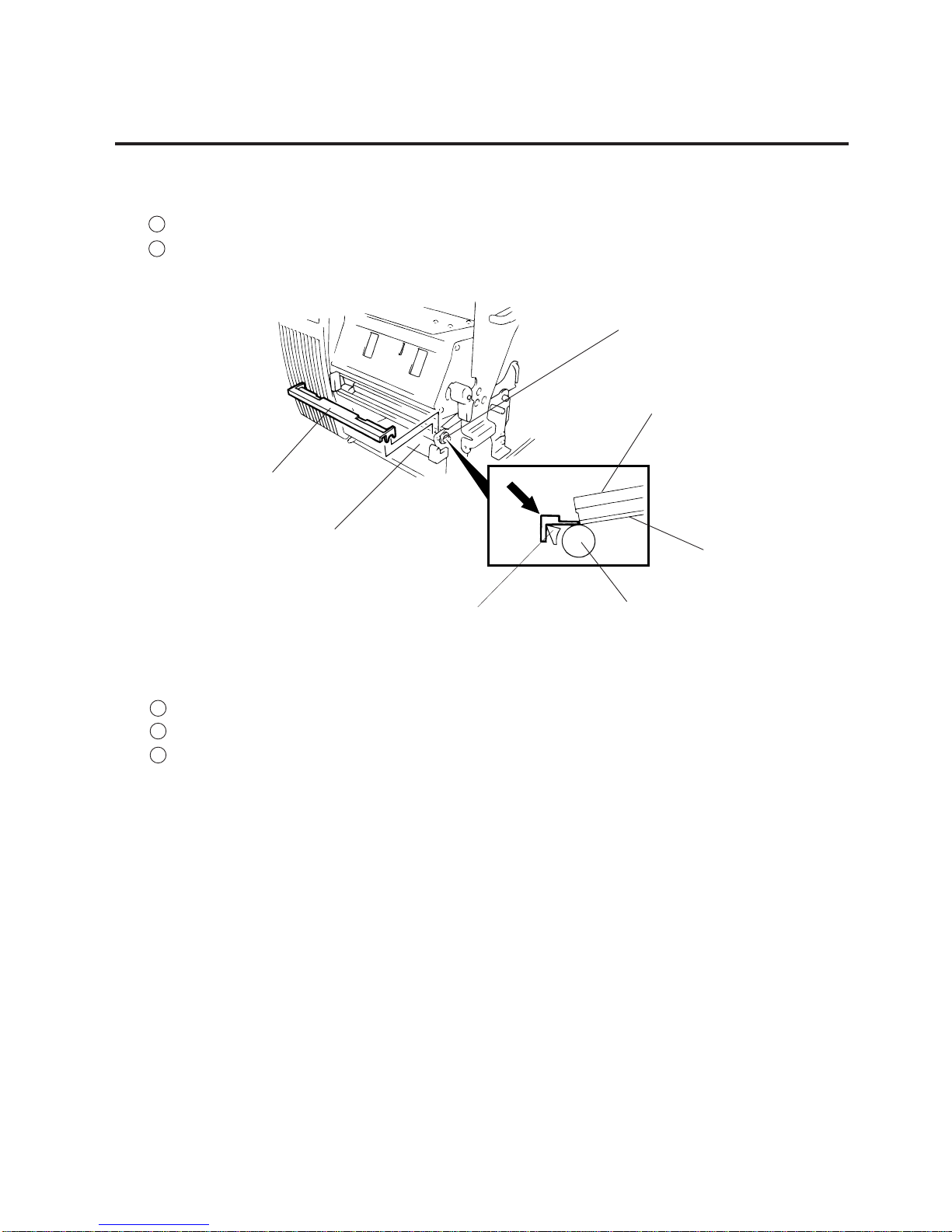
3.1 HIGH SPEED PC INTERFACE BOARD (B-4800-PC-QM)
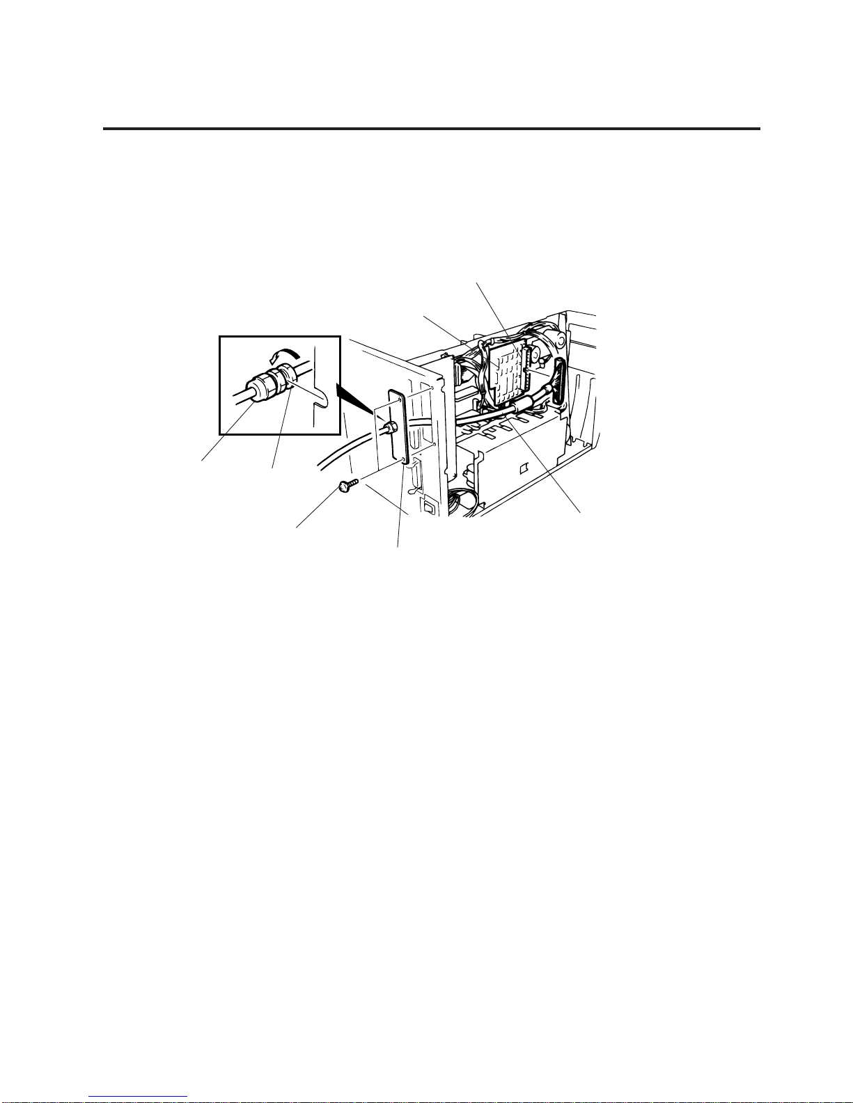
6. Connect the printer cable to the connector (CN1) on the BPE PC board.
7. Put the cable strain relief of the printer cable in the notch of the cable support plate. Secure the cable
strain relief to the cable support plate by turning the nut.
8. Attach the cable support plate to the printer with the FL3x5 screws removed in step 2.
Connector (CN1)
BPE PC Board
Printer Cable
Cable Support Plate
Screw (FL-3x5)
Nut
Cable Strain Relief
3-3
EM18-33010A
3. INSTALLATION PROCEDURE FOR THE OPTIONAL EQUIPMENT
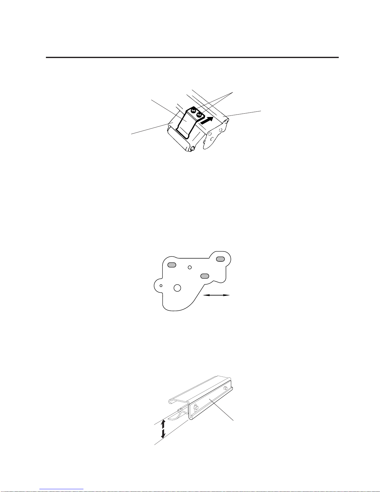
5. Unclamp and disconnect the connector for the strip sensor from CN5 on the CPU PC board.
6. Remove the SM-4x6B screw to detach the strip sensor (LED)/(Tr).
Fig. 3-3
Fig. 3-4
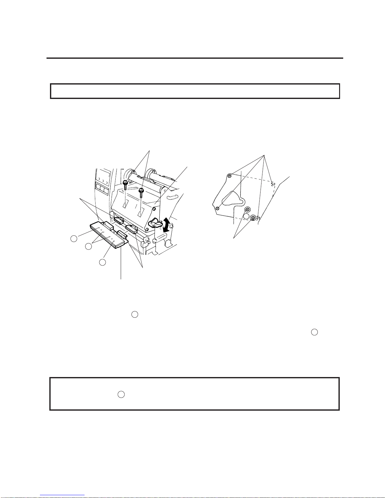
3.2 CUTTER MODULE (B-4205-QM)
3.2 CUTTER MODULE (B-4205-QM)
NOTE: For the B-570 series, the take-up/cutter harness enclosed with the B-4205-QM is not used but
the take-up harness connected to CN2 on the PWM PC board.
1. Remove the top cover and left side cover. (See Fig. 2-1.)
2. Remove the I/F PC board. (See Fig. 2-2.)
3. Remove the front plate. (See Fig. 2-6.)
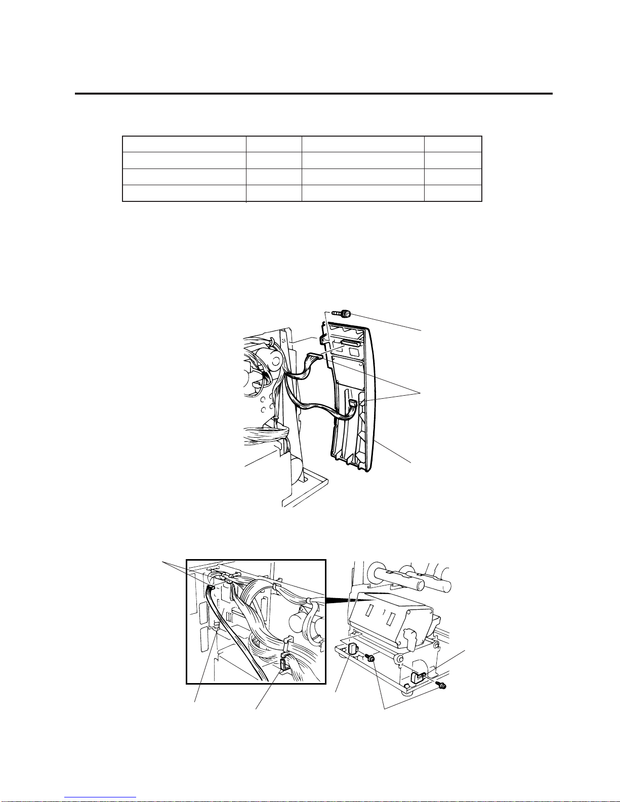
4. Remove the screw (SM-4x8B) and two connectors to detach the operation panel.
Description Q’ty/Unit Description Q’ty/Unit
Cutter Unit 1 Cutter Attaching Screw 2
Cutter Cover 1 Screw (FL-4x6) 1
Take-up/Cutter Harness 1 Cleaner 1
Screw (SM-4x8B)
Connector
Operation Panel
Connector (CN5)
CPU PC Board
Clamp
Strip Sensor (Tr)
Screw (SM-4x6B)
Strip Sensor (LED)
3-4
EM18-33010A
3. INSTALLATION PROCEDURE FOR THE OPTIONAL EQUIPMENT
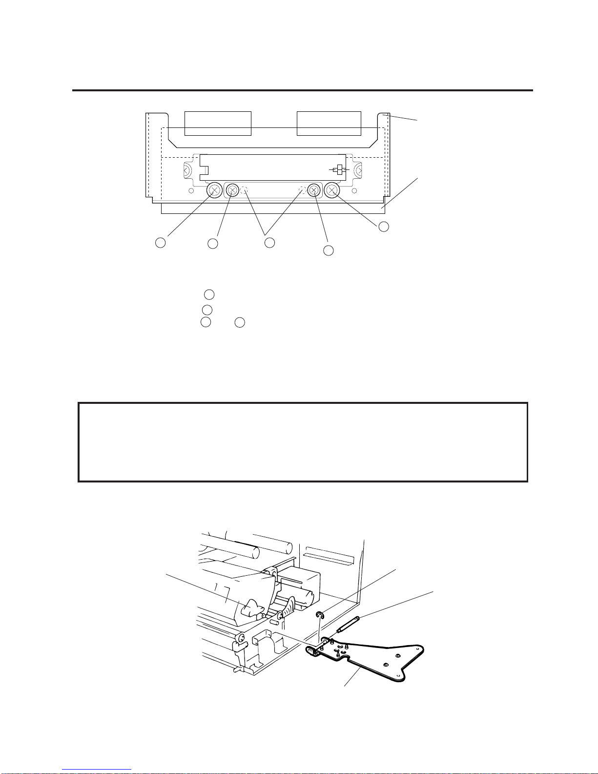
Fig. 3-5
Fig. 3-6
3.2 CUTTER MODULE (B-4205-QM)
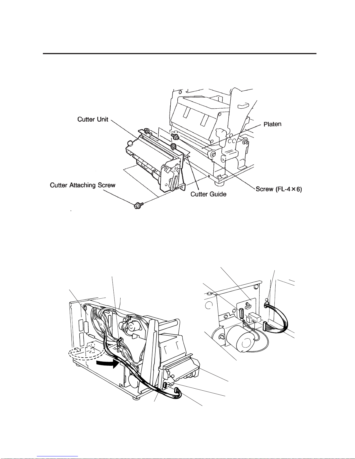
7. Install the cutter unit with the attached screws (cutter attaching screw, FL-4x6).
When installing the cutter, make sure that the cutter guide is not in contact with the platen. If it is, print
failure or noise may be caused.
8. Remove the motor cover. (See Fig. 2-9.)
9. Disconnect the connector from CN2 on the PWM PC board.
Clamp and pass the cable through the opening and connect it to the CN1 on the Cutter I/F PC board.
Clamp
CPU PC Board
Connector (CN2)
PWM PC Board
Opening
Cable
Cut I/F PC Board
Cutter Unit
Connector (CN2)
SVO7A1003: Nov. 21 ’97
3-5
EM18-33010A
3. INSTALLATION PROCEDURE FOR THE OPTIONAL EQUIPMENT
Fig. 3-8
(Revision Date Aug. 11, ’95)
3.2 CUTTER MODULE (B-4205-QM)
■ Adjusting the Cutter Guide Plates
After replacing the cutter unit the following adjusting procedure should be employed to prevent paper
jams.
1. Attach the cutter guide plate A with two SM-4x6C screws so that the fixed cutter is positioned 0.1
mm to 0.4 mm above the bottom of the cutter guide plate A.
2. Attach the cutter guide plate B with two FL-4x8 screws so that there is a clearance of 0.5 mm between
the cutter guide plate A and cutter guide plate B using a clearance gauge.
10. Mount the cutter cover with the two screws.
11. Reassemble the motor cover, rewind full sensor (Tr), I/F PC board, left side cover and top cover in
order.
12. After reassembly is complete, perform a test print to confirm that the cutter works properly.
After printing a print sample at a speed of 8”/sec., feed the media about 33 mm and check that the
swing cutter works without error. After cutting the media, feed the media about 33 mm in the reverse
direction and check that it correctly stops at the print start position.
NOTES: 1. If the top edge of label winds onto the platen in cut issue, set DIP SW. 1-5 to ON.
(Refer to the Owner’s Manual.)
2. Retain the parts that are removed during installation of the cutter unit. They will be
required when the printer is modified to a standard type.
Fig. 3-7
Removed Parts
Front plate
Black screws
Q’ty/Unit
1
2
Q’ty/Unit
1
2
Removed Parts
Strip sensor (LED)/(Tr)
Screw (P-4x6)
Cutter Cover
Screw
Cutter Attaching Screw
Cutter Guide Plate A
Screw
(SM-4x6C)
0.1 - 0.4 mm
0.5 mm
Cutter Guide Plate B
Screw
(FL-4x8)
Fixed Cutter
3-6
EM18-33010A
3. INSTALLATION PROCEDURE FOR THE OPTIONAL EQUIPMENT
Max. drawing size (on-the-fly)
(W)x(H) (mm)
138.0 x 149.3
138.0 x 234.6
138.0 x 320.0
138.0 x 405.3
138.0 x 490.7
138.0 x 576.0
138.0 x 661.3
3.3 MEMORY MODULE
1. Remove the top cover and left side cover. (See Fig. 2-1.)
2. Hold the memory module so that the Pin 1 is on the upper right, then attach the memory module to
the IC socket. Expanding the memory must be performed in sequence, IC19, IC20, IC21, IC22, IC23
and IC24.
Fig. 3-9
3.3 MEMORY MODULE
3. Reassemble the left side cover in the reverse order of removal.
■ Expansion memory and drawing size
*: The size for the tag paper is 138.0x997.0.
RAM
Capacity
1MB
1.5MB
2MB
2.5MB
3MB
3.5MB
4MB
IC No.
IC17, 18
IC17~19
IC17~20
IC17~21
IC17~22
IC17~23
IC17~24
Remarks
Standard
Option
Option
Option
Option
Option
Option
Max. drawing size (normal)
(W)x(H) (mm)
138.0 x 298.6
138.0 x 469.3
138.0 x 640.0
138.0 x 810.7
138.0 x 981.4
Batch Strip
Auto-cut
*138.0 x 995.0
*138.0 x
991.0
*138.0 x 995.0
*138.0 x
991.0
Batch Strip
Auto-cut
Memory Module
Pin 1
IC24
IC Socket
IC19
CPU PC Board

3-7
EM18-33010A
3. INSTALLATION PROCEDURE FOR THE OPTIONAL EQUIPMENT
3. Remove the FL-4x5 screw to detach the blind plate on the back of the printer and attach the fanfold
paper guide (rear) with the same screw.
(Revision Date Apr. 28, ’95)
3.4 FANFOLD PAPER GUIDE MODULE (B-4905-FF-QM)
3.4 FANFOLD PAPER GUIDE MODULE (B-4905-FF-QM)
1. Open the top cover.
2. Remove the T-4x8 screws to detach the paper guide ass’y at the center of the printer and attach the
fanfold paper guide (front) with these same screws.
Description
Fanfold Paper Guide(rear)
Fanfood Paper Guide (front)
Q’ty/Unit
1
1
Fig. 3-10
Fig. 3-11
Screw (T-4x8)
Fanfold Paper Guide
(front)
Screw (FL-4x5)
Screw (FL-4x5)
Fanfold Paper Guide (rear)
4-1
EM18-33010A
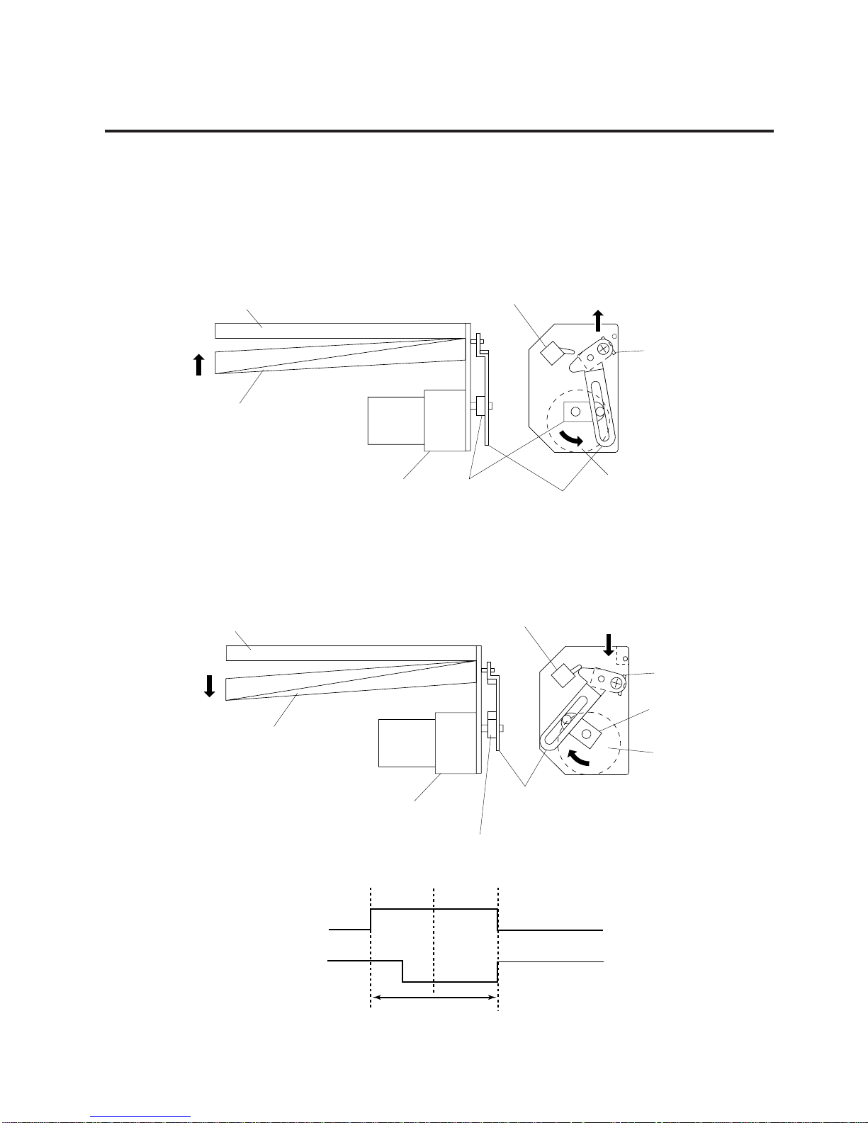
4. MECHANISM DESCRIPTION
After making a cut, the arm turns the micro switch off and the cutter home position is detected.
When the cutter does not return to the home position because of a paper jam, an error occurs and the
next piece of paper will not be cut.
Fig. 4-1
Fig. 4-2
4. MECHANISM DESCRIPTION
4.1 CUTTER DRIVE (CUTTER MODE)
The printer supplies DC + 27 V to the cutter motor to rotate the cutter motor and clutch counter clockwise.
The arm swings like a pendulum and moves the fixed slide cutter up and down to make a cut.
4.1 CUTTER DRIVE (CUTTER MODE)
Timing chart
Open
+ 27
Close
Open
MOTOR
CHOME
Micro Switch
Cutting
(one cycle)
Slide Cutter
Micro Switch
Cutter Motor
Cutter Motor Clutch
Slide Cutter
Fixed Cutter
Slide Cutter
Clutch
Cutter Motor
Micro Switch
Cutter Motor
Fixed Cutter
Slide Cutter
Arm
Arm
Clutch
 Loading...