

Toshiba TEC B-450-HS-QQ Series, TEC B-452-HS12-QQ, TEC B-452-HS12-QQ-US Owner's Manual
TEC Label Printer
B-450-HS-QQ SERIES
Owner’s Manual
Copyright © 2000
by TOSHIBA TEC CORPORATION
All Rights Reserved
570 Ohito, Ohito-cho, Tagata-gun, Shizuoka-ken, JAPAN
This equipment has been tested and found to comply with the limits for a Class A digital device, pursuant
to Part 15 of the FCC Rules. These limits are designed to provide reasonable protection against harmful
interference when the equipment is operated in a commercial environment. This equipment generates,
uses, and can radiate radio frequency energy and, if not installed and used in accordance with the
instruction manual, may cause harmful interference to radio communications.
Operations of this equipment in a residential area is likely to cause harmful interference in which case
the user will be required to correct the interference at his own expense. (for USA only)
"This Class A digital apparatus meets all requirements of the Canadian Interference-Causing Equipment
Regulations."
"Cet appareil numérique de la classe A respecte toutes les exigences du Règlement sur le matériel
brouilleur de Canada."
(for CANADA only)
Changes or modifications not expressly approved by manufacturer for compliance could void the user's
authority to operate the equipment.
(for QQ only)
(i)
Safety Summary
EO1-33019
Safety Summary
Personal safety in handling or maintaining the equipment is extremely important. Warnings and Cautions
necessary for safe handling are included in this manual. All warnings and cautions contained in this
manual should be read and understood before handling or maintaining the equipment.
Do not attempt to effect repairs or modifications to this equipment. If a fault occurs that cannot be rectified
using the procedures described in this manual, turn off the power, unplug the machine, then contact your
authorized TOSHIBA TEC representative for assistance.
Meanings of Each Symbol
This symbol indicates warning items (including cautions).
Specific warning contents are drawn inside the symbol.
(The symbol on the left indicates a general caution.)
This symbol indicates prohibited actions (prohibited items).
Specific prohibited contents are drawn inside or near the symbol.
(The symbol on the left indicates “no disassembling”.)
This symbol indicates actions which must be performed.
Specific instructions are drawn inside or near the symbol.
(The symbol on the left indicates “disconnect the power cord plug from the outlet”.)
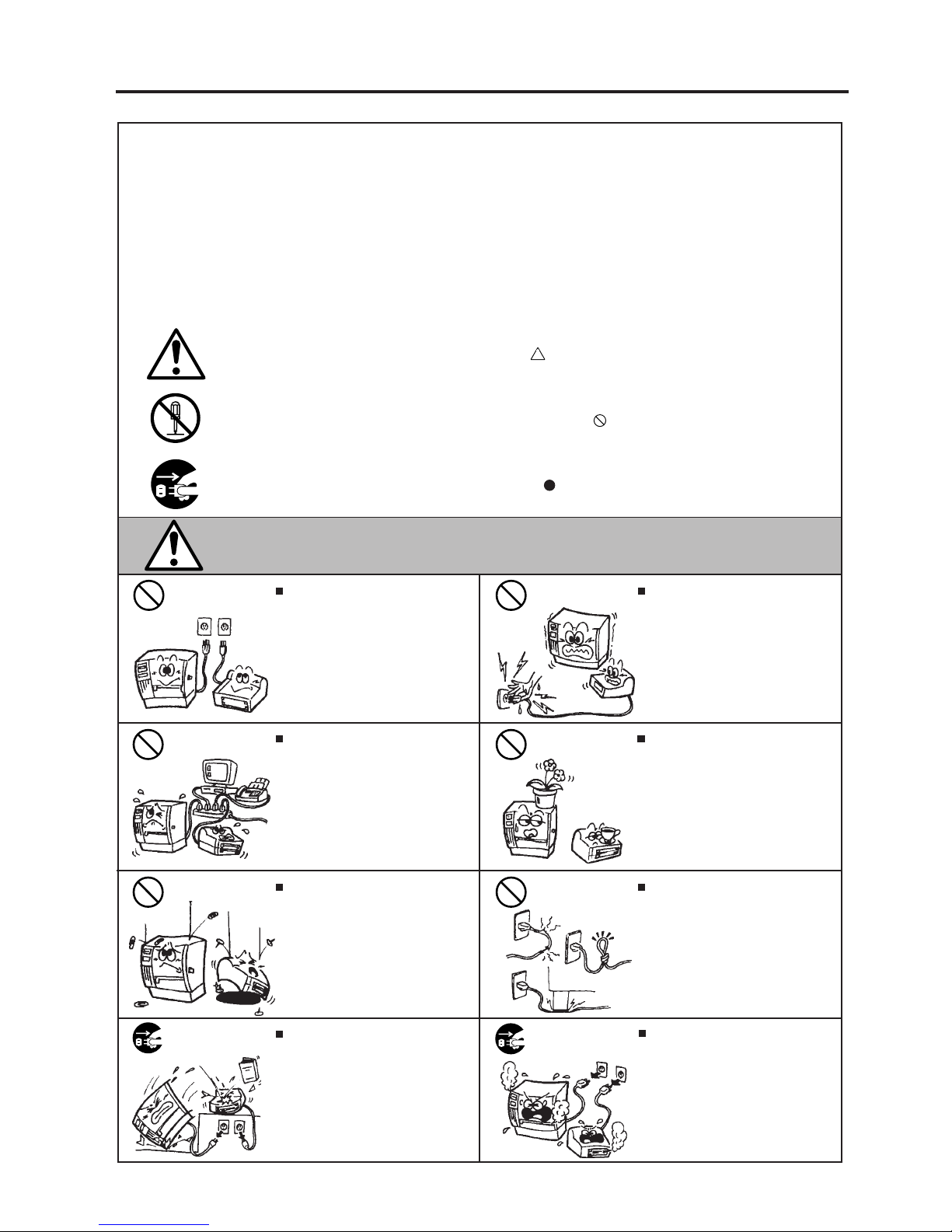
Do not use voltages other than the
voltage (AC) specified on the rating
plate, as this may cause fire or
electric shock.
Any other than the
specified AC voltage
is prohibited.
WARNING
This indicates that there is the risk of death or serious injury if the
machines are improperly handled contrary to this indication.
Prohibited
Do not plug in or unplug the power
cord plug with wet hands as this may
cause electric shock.
Do not place metal objects or
water-filled containers such as flower
vases, flower pots or mugs, etc. on
top of the machines. If metal objects
or spilled liquid enter the machines,
this may cause fire or electric
shock.
If the machines share the same
outlet with any other electrical
appliances which consume large
amounts of power, the voltage will
fluctuate widely each time these
appliances operate. Be sure to
provide an exclusive outlet for the
machine as this may cause the
machines to malfunction.
Do not insert or drop metal,
flammable or other foreign objects into
the machines through the ventilation
slits, as this may cause fire or electric
shock.
Prohibited
Prohibited
Prohibited
Do not scratch, damage or modify
the power cords. Also, do not place
heavy objects on, pull on, or excessively bend the cords, as this may
cause fire or electrical shock.
Prohibited
Continued use of the machines in an
abnormal condition such as when the
machines are producing smoke or
strange smells may cause fire or elec-
tric shock. In these cases, immediately turn off the power switches and
disconnect the power cord plugs from
the outlet. Then, contact your authorized TOSHIBA TEC representative for
assistance.
Disconnect
the plug.
If the machines are dropped or their
cabinets damaged, first turn off the
power switches and disconnect the
power cord plugs from the outlet, and
then contact your authorized
TOSHIBA TEC representative for
assistance. Continued use of the
machine in that condition may cause
fire or electric shock.
Disconnect
the plug.
(ii)
Safety Summary
EO1-33019
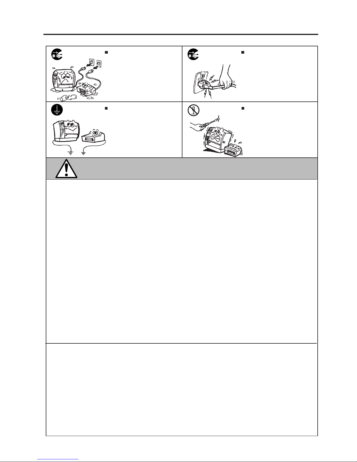
CAUTION
This indicates that there is the risk of personal Injury or damage to
objects if the machines are improperly handled contrary to this indication.
If foreign objects (metal fragments,
water, liquids) enter the machines,
first turn off the power switches and
disconnect the power cord plugs from
the outlet, and then contact your
authorized TOSHIBA TEC representative for assistance. Continued
use of the machine in that condition
may cause fire or electric shock.
Disconnect
the plug.
Do not remove covers, repair or
modify the machine by yourself. You
may be injured by high voltage, very
hot parts or sharp edges inside the
machine.
No disassembling.
Ensure that the equipment is
properly grounded. Extension cables
should also be grounded. Fire or
electric shock could occur on
improperly grounded equipment.
Connect a
grounding
wire.
When unplugging the power cords,
be sure to hold and pull on the plug
portion. Pulling on the cord portion
may cut or expose the internal wires
and cause fire or electric shock.
Disconnect
the plug.
Precautions
The following precautions will help to ensure that this machine will continue to function correctly.
• Try to avoid locations that have the following adverse conditions:
* Temperatures out of the specification * Direct sunlight * High humidity
* Shared power source * Excessive vibration * Dust/Gas
• The cover should be cleaned by wiping with a dry cloth or a cloth slightly dampened with a mild
detergent solution. NEVER USE THINNER OR ANY OTHER VOLATILE SOLVENT on the plastic
covers.
• USE ONLY TOSHIBA TEC SPECIFIED paper and ribbons.
• DO NOT STORE the paper or ribbons where they might be exposed to direct sunlight, high temperatures, high humidity, dust, or gas.
• Ensure the printer is operated on a level surface.
• Any data stored in the memory of the printer could be lost during a printer fault.
• Try to avoid using this equipment on the same power supply as high voltage equipment or equipment likely to cause mains interference.
• Unplug the machine whenever you are working inside it or cleaning it.
• Keep your work environment static free.
• Do not place heavy objects on top of the machines, as these items may become unbalanced and fall
causing injury.
• Do not block the ventilation slits of the machines, as this will cause heat to build up inside the
machines and may cause fire.
• Do not lean against the machine. It may fall on you and could cause injury.
• Care must be taken not to injure yourself with the printer paper cutter.
• Unplug the machine when it is not used for a long period of time.
Request Regarding Maintenance
• Utilize our maintenance services.
After purchasing the machine, contact your authorized TOSHIBA TEC representative for assistance
once a year to have the inside of the machine cleaned. Otherwise, dust will build up inside the
machines and may cause a fire or a malfunction. Cleaning is particularly effective before humid
rainy seasons.
• Our preventive maintenance service performs the periodic checks and other work required to
maintain the quality and performance of the machines, preventing accidents beforehand.
For details, please consult your authorized TOSHIBA TEC representative for assistance.
• Using insecticides and other chemicals
Do not expose the machines to insecticides or other volatile solvents. This will cause the cabinet or
other parts to deteriorate or cause the paint to peel.

TABLE OF CONTENTS
1. INTRODUCTION ....................................................................................1- 1
1.1 APPLICABLE MODEL ...................................................................1- 1
1.2 ACCESSORIES .............................................................................1- 1
2. SPECIFICATIONS .................................................................................2- 1
2.1 GENERAL SPECIFICATIONS.......................................................2- 1
2.2 PRINTING SPECIFICATIONS.......................................................2- 1
2.3 PAPER (LABEL) SPECIFICATIONS .............................................2- 2
2.4 RIBBON SPECIFICATIONS ..........................................................2- 2
2.5 OPTION .........................................................................................2- 2
3. APPEARANCE ......................................................................................3- 1
3.1 FRONT/REAR VIEW......................................................................3- 1
3.2 OPERATION PANEL .....................................................................3- 1
4. DIP SWITCH FUNCTIONS ....................................................................4- 1
5. SETUP PROCEDURE............................................................................5- 1
5.1 REQUIREMENTS FOR OPERATION ...........................................5- 1
5.2 SETTING UP THE PRINTER.........................................................5- 1
6. INSTALLATION PROCEDURE .............................................................6- 1
6.1 INSTALLING THE SUPPLY HOLDER UNIT .................................6- 1
6.2 INSTALLING THE SUPPLY COVER.............................................6- 1
6.3 CONNECTING THE POWER CORD AND CABLES.....................6- 2
7. LOADING THE RIBBON........................................................................7- 1
8. LOADING THE PAPER .........................................................................8- 1
9. THRESHOLD SETTING.........................................................................9- 1
10. CARE/HANDLING OF THE PAPER AND RIBBON............................10- 1
11. GENERAL MAINTENANCE ................................................................11- 1
11.1 CLEANING...................................................................................11- 1
11.2 COVERS......................................................................................11- 2
11.3 REMOVING JAMMED PAPER ....................................................11- 3
12. TROUBLESHOOTING .........................................................................12- 1
APPENDIX ..................................................................................................13- 1
INDEX
Page
CAUTION:
1. This manual may not be copied in whole or in part without prior written permission of TOSHIBA
TEC.
2. The contents of this manual may be changed without notification.
3. Please refer to your local Authorized Service representative with regard to any queries you may
have in this manual.
EO1-33019
1-1
1. INTRODUCTION
EO1-33019
1.1 APPLICABLE MODEL
1. INTRODUCTION
Thank you for choosing the TEC B-450 Series thermal transfer printer. This new generation high
performance high quality printer is equipped with the latest hardware including the newly developed high
density (23.6 dots/mm 600 dots/inch) print head. This allows very clear print at a maximum speed of 50.8
mm/sec. (2 inch/sec.). Other standard features include an external paper supply.
Optional features include a strip mechanism and cutter mechanism.
This manual contains general set-up and maintenance information and should be read carefully to help
gain maximum performance and life from your printer. For most queries please refer to this manual and
keep it safe for future reference.
1.1 APPLICABLE MODEL
• B-452-HS12-QQ
• B-452-HS12-QQ-US
Model name description
B - 4 5 2 - H S 1 2 - Q Q
Destination Code
QQ-US: North America Block, QQ: Except for QQ-US
Specification
12: with Centronics interface and expansion I/O interface
Issue mode
S: Batch
Resolution
H: 23.6 dots/mm (600 dpi)
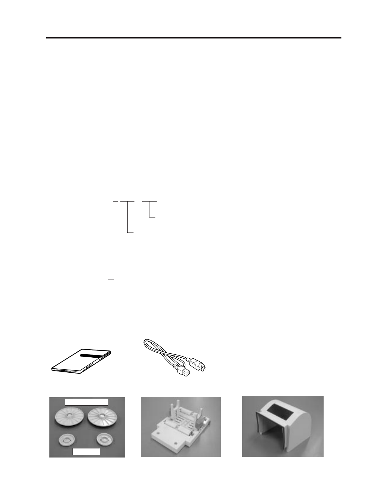
1.2 ACCESSORIES
Owner's Manual
(EO1-33019)
Power Cord
Supply Holder Unit
Supply Holder
Spacer
Supply Cover
2-1
2. SPECIFICATIONS
EO1-33019
Supply voltage 100 - 120V, 60Hz
Power consumption 1.8 A, 140 W max. (standby: 0.22 A, 13.5 W)
Operating temperature 5˚C ~ 40˚C
Relative humidity 25% ~ 85%RH (no condensation)
Dimensions 268 mm (width) x 244 mm (height) x 198 mm (depth), with Supply holder
unit 410 mm (depth)
Weight Printer: 5.0 kg (without paper and ribbon)
Supply Holder + Supply Cover: 2.5 kg
2. SPECIFICATIONS
2.1 GENERAL SPECIFICATIONS
2.1 GENERAL SPECIFICATIONS
B-452-HS12-QQ
Item
Model
∗
Data MatrixTM is a trademark of International Data Matrix, Inc.
PDF417 is a trademark of Symbol Technologies, Inc.
QR code is a trademark of DENSO CORPORATION.
Maxi code is a trademark of United Parcel Service of America, Inc.
2.2 PRINTING SPECIFICATIONS
Print head Thermal print head 23.6 dots per mm (600 dots per inch)
Printing method Thermal transfer
Print speeds 50.8 mm/sec. (2 inch/sec.)
Maximum print width 103.6 mm (4.08 inches)
Dispensing modes Batch (Continuous), Strip (Option) and Cut modes (Option)
(Both cut and strip modes are available only when their respective modules
are fitted.)
Available bar-code types JAN8, JAN13, EAN8, EAN8 + 2 digits, EAN8 + 5 digits
EAN13, EAN13 + 2 digits, EAN13 + 5 digits
UPC-E, UPC-E + 2 digits, UPC-E + 5 digits
UPC-A, UPC-A + 2 digits, UPC-A + 5 digits, UPC-B
MSI, ITF, NW-7, CODE39, CODE93, CODE128, EAN128
Industrial 2 to 5, UCC/EAN128, Customer bar code, POSTNET
RM4SCC, KIX code
Two-dimensional code Data Matrix, PDF417, QR code, Maxi code
Graphics All types of graphic files are available when using the windows driver.
However, only BMP and PCX files are available when using the program-
ming commands.
Fonts Times Roman (6 sizes), Helvetica (6 sizes), Presentation (1 size),
Letter Gothic (1 size), Prestige Elite (2 sizes), Courier (2 sizes),
OCR (2 types), Writable characters, Outline font (7 type), Ture Type fonts
Optional True Type Fonts (20 type)
Rotations 0˚, 90˚, 180˚, 270˚
Standard interfaces Serial interface (RS-232C)
Parallel interface (Centronics)
Expansion I/O interface
Keyboard interface
B-452-HS12-QQ
Item
Model
2-2
2. SPECIFICATIONS
EO1-33019
2.3 PAPER (LABEL) SPECIFICATIONS
2.3 PAPER (LABEL) SPECIFICATIONS
NOTES: 1. To ensure good print quality and maximum print head life use only TOSHIBA TEC specified paper
and ribbons.
2. For further information about paper and ribbon, refer to Section 10. CARE/HANDLING OF THE
PAPER AND RIBBON.
Type Spool type
Width 60 mm ~ 110 mm
Length (270 m)
Outer diameter Ø65 mm (max.)
2.4 RIBBON SPECIFICATIONS
2.5 OPTION
[Unit: mm]
Span of one label
Label length
Width including backing paper
Label width
Gap length
Black mark length
Effective print width
Effective print length
Print speed up/slow down area
Outer roll diameter
Thickness (Backing paper + label)
Thickness of backing paper
Label dispensing mode
Item
Batch mode
Strip mode Cut mode
25.4 ~ 999.0
23.4 ~ 997.0
25.4 ~ 110.0
20.0 ~ 107.0
2.0 ~ 20.0
2.0 ~ 10.0
10.0 ~ 103.6
21.4 ~ 200.0
1.0
MAX. ø152.4 (Paper Core ø38, 40, 42 or 76.2)
0.13 ~ 0.17
0.056 ~
2.0 ~ 20.0
3.0 ~ 200.0
6.0 ~ 20.0
29.0 ~ 200.0
0.1 ~ 0.17
0.1 ~ 0.17
7.0 ~ 999.0
5.0 ~ 997.0
37.0 ~ 999.0
31.0 ~ 993.0
NOTE: To purchase the OPTIONAL KIT, please contact your authorized TOSHIBA TEC represen-
tative or TOSHIBA TEC Head Quarter.
Description
A stop-and-cut rotary cutter
This module strips the label from the backing paper with
the take-up block and strip block.
This module is an external intelligent keyboard unit.
Option Name
Cutter module
Strip module
Keyboard module
Type
B-7204-QM
B-7904-H-QM
KB-80-QM
3-1
3. APPEARANCE
EO1-33019
3. APPEARANCE
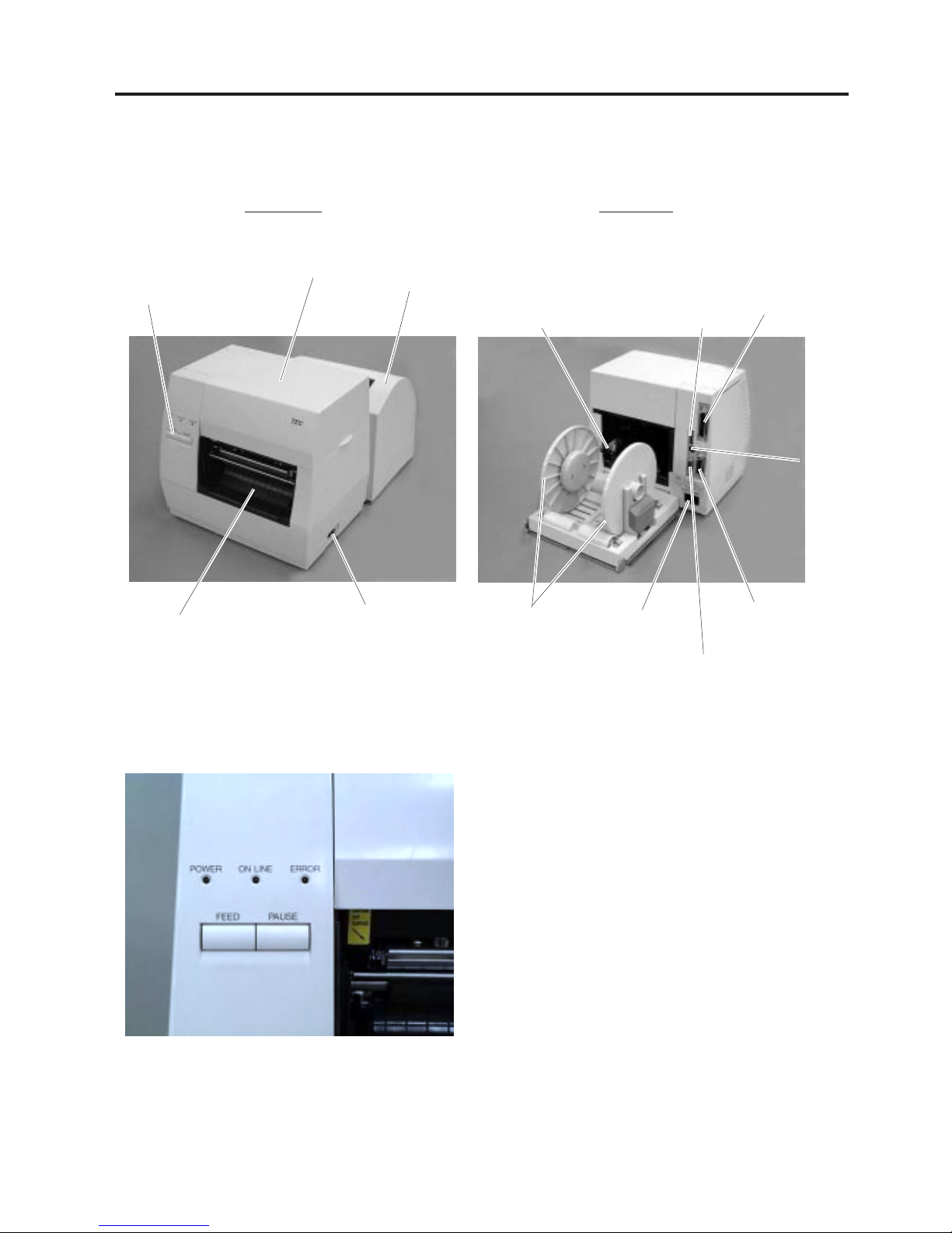
3.1 FRONT/REAR VIEW
3.1 FRONT/REAR VIEW
Front View Rear View
3.2 OPERATION PANEL
POWER LED (Green)
Lights when the power is turned on.
ON-LINE LED (Green)
1) Flashes when communicating with a host computer.
2) On while printing.
ERROR LED (Red)
Lights when a communication error occurs, when the
paper/ribbon ends or the printer is not operating correctly.
FEED Key
Feeds paper.
PAUSE Key
Pauses printing.
Resets the printer when paused or when an error
occurs.
Fig. 3-2
Operation Panel
Power Switch
O : OFF
I:ON
Paper Outlet
Fig. 3-1
DIP Switch
Top Cover
Paper Guide Lock Lever
Supply Holder
AC Power Inlet
Serial Interface Connector (RS-232C)
Keyboard
Connector
Parallel Interface
Connector (Centronics)
Expansion I/O
Interface Connector
Supply Cover

4-1
4. DIP SWITCH FUNCTIONS
EO1-33019
4. DIP SWITCH FUNCTIONS
The DIP switches are located at the rear of the printer.
4. DIP SWITCH FUNCTIONS
DIP SW
Fig. 4-1
WARNING!
Turn the POWER OFF before
changing the DIP switches.
No.
1
2
3
4
5
6
7
8
ON/OFF
1
OFF
ON
OFF
ON
2
OFF
OFF
ON
ON
OFF
ON
OFF
ON
OFF
ON
6
OFF
ON
OFF
ON
7
OFF
OFF
ON
ON
OFF
ON
Function
2400 bps
4800 bps
9600 bps
19200 bps
None
EVEN
Not available
Available
Available
Not available
RAM clear mode (Maintenance counter)
Threshold manual setting mode
Sensor adjustment mode
RAM clear mode (Parameter)
Normal operation mode
Program down load operation
Remarks
Transmission speed
(Baud rate)
Parity
Stacker
Auto media feed
Selectable only when
DIP SW #8 is ON.
Operating mode
DIP SW
NOTES: 1. DIP Switch settings are read at power on time.
2. To enter the program download mode first set DIP SW #8 to ON. The printer will then enter
down the [FEED] or [FEED] and [PAUSE]
keys whilst turning the power on. If the printer
is turned on without pressing a key, it will enter the program download mode.
Do not set the switches to the maintenance mode as this may cause a failure.
the relevant modes, as selected by DIP SWS #6 and #7. To initialize these modes hold
5-1
5. SET UP PROCEDURE
EO1-33019
5. SET UP PROCEDURE
5.1 REQUIREMENTS FOR OPERATION
This machine has the following requirements:
• The host computer must have a serial port or centronics parallel port.
• To communicate with host, either an RS-232C cable or Centronics cable is required.
(1) RS-232C cable..........9 pins
(2) Centronics cable .......36 pins
• To print a label format, create the complete program using the interface/communication manual or use
a bespoke labelling package or Windows Driver.
■ Interface Cables
To prevent radiation and reception of electrical noise, the interface cables must meet the following
requirements:
• Fully shielded and fitted with metal or metalised connector housings.
• Kept as short as possible.
• Should not be bundled tightly with power cords.
• Should not be tied to power line conduits.
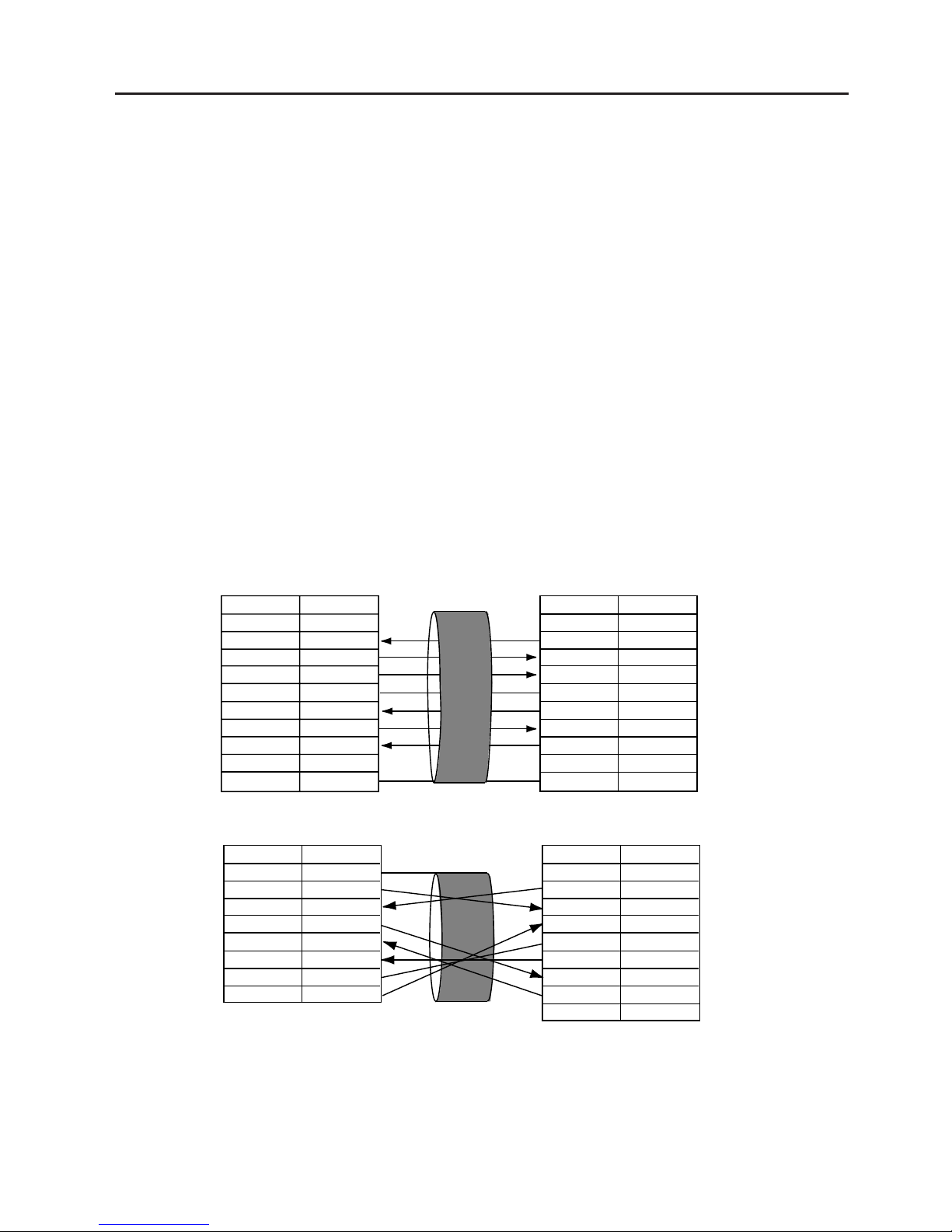
■ RS-232C Cable description
The serial data cable used to connect the printer to the host computer should be one of the following two
types:
NOTE:Use an RS-232C cable with imperial (inch) connector securing screws.
5.1 REQUIREMENTS FOR OPERATION
DB-9S
Connector to PC
DB-9P
Connector to Printer
DB-25S
Connector to PC
DB-9P
Connector to Printer
PIN No.
1
2
3
4
5
6
7
8
9
Housing
Signal
N.C.
RXD
TXD
DTR
GND
DSR
RTS
CTS
N.C.
Shield
PIN No.
1
2
3
4
5
6
7
8
9
Housing
Signal
N.C.
TXD
RXD
DSR
GND
DTR
CTS
RTS
N.C.
Shield
PIN No.
1
2
3
4
5
6
7
20
Signal
Shield
TXD
RXD
RTS
CTS
DSR
GND
DTR
PIN No.
1
2
3
4
5
6
7
8
9
Signal
N.C.
TXD
RXD
DSR
GND
DTR
CTS
RTS
N.C.
5.2 SETTING UP THE PRINTER
• Place the printer on a flat, stable surface.
• Use a grounded electrical outlet do not use adapter plug.
• Be sure there is adequate room around the printer for easy operation and maintenance.
• Keep your work environment static free.
Fig. 5-1
 Loading...