

Toshiba TE-62-BP, TE-78-BP, TE-112-BP, TE-92-BP, TE-150-BP Quick Start Up Manual
...
Buy: www.ValinOnline.com | Phone 844-385-3099 | Email: CustomerService@valin.com
QUICK STARTUP GUIDE
TE Series
Digital
Solid State Soft Starter
DOCUMENT: NBZ0004
18 – 1250A
Basic Installation
Issued: 9/12
and
Quick Startup
Guide
Firmware Version 4.31

Buy: www.ValinOnline.com | Phone 844-385-3099 | Email: CustomerService@valin.com

Basic Insta
l
lati
u
i
E
igital
S
8
–
Buy: www.ValinOnline.com | Phone 844-385-3099 | Email: CustomerService@valin.com
on and Operation G
Important Notice
The instructions contained in this manual are not intended to cover all details or variations in equipment
types nor may it provide for every possible contingency concerning the installation, operations, or
maintenance of this equipment. Should additional information be required, contact your Toshiba
Customer Support Center.
The contents of this manual shall not become a part of or modify any prior or existing agreement,
commitment, or relationship. The sales contract contains the entire obligation of Toshiba Inte rnational
Corporation. The warranty contained in the contract between the parties is the sole warranty of Toshiba
International Corporation and any statements contained herein do not create new warrantie s or modify
the existing warranty.
Any electrical or mechanical modifications to this equipment without the prior written consent of
Toshiba International Corporation may void all warranties or other safety certifications.
Unauthorized modifications may also result in safety hazard or equipment damage.
Misuse of this equipment could result in injury and equipment damage. In no event will Toshiba
International Corporation be responsible or liable for direct, indirect, special, or consequential
damage or injury that may result from the misuse of this equipment.
de
T
Series D
olidState Soft Starters 1
1250A
About This Manual
Every effort has been made to provide accurate and concise information to you, our customer.
At Toshiba International Corporation we are continuously striving for better ways to meet the constantly
changing needs of our customers. E-mail your comments, questions, or concerns about this
publication to Toshiba.

Basic Insta
l
lati
u
i
E
igital
S
8
–
Buy: www.ValinOnline.com | Phone 844-385-3099 | Email: CustomerService@valin.com
on and Operation G
de
Purpose and Scope of Manual
This manual provides information on how to safely install, operate, maintain, and dispose of your TE
solid state starter. The information provided in this manual is applicable to the TE starter only.
This manual provides information on the various features and functions of this powerful device,
including:
• Installation
• Operation
• Mechanical and electrical specifications.
Included is a section on general safety instructions that describe the warning labels and symbols that
are used on the device and throughout the manual. Read the manual completely before installing,
operating, performing maintenance, or disposing of this equipment.
T
Series D
olidState Soft Starters 1
1250A
This manual and the accompanying drawings should be considered a permanent part of the equipment
and should be readily available for reference and review. Dimensions shown in the manual are in
imperial units and/or the metric equivalent. Connection drawings within this document convey the typical
topology of the TE starter.
Because of our commitment to continuous improvement, Toshiba International Corporation reserves the
right, without prior notice, to update information, make product changes, or to discontinue any product or
service identified in this publication.
Toshiba International Corporation (TIC) shall not be liable for direct, indirect, special, or
consequential damages resulting from the use of the information contained within this manual.
This manual is copyrighted. No part of this manual may be photocopied or reproduced in any form
without the prior written consent of Toshiba International Corporation.
© Copyright 2012 Toshiba International Corporation.
TOSHIBA® is a registered trademark of Toshiba Corporation. All other product or trade references
appearing in this manual are registered trademarks of their respective owners.
All rights reserved.
Printed in the U.S.A.

l
lati
u
i
T
E
igital
S
8
–
Buy: www.ValinOnline.com | Phone 844-385-3099 | Email: CustomerService@valin.com
Basic Insta
on and Operation G
de
Series D
Contacting TIC’s Customer Support Center
Toshiba International Corporation’s Customer Support Center can be contacted to obtain hel p in
resolving any system problem that you may experience or to provide application information.
The Support Center is open from 8 a.m. to 5 p.m. (CST), Monday through Friday. The Center’s toll free
number is US (800) 231-1412/Fax (713) 937-9349 CAN (800) 872-2192 MEX 01 (800) 527-1204.
For after-hours support follow the directions of the outgoing message when calling.
You may also contact Toshiba International Corporation by writing to:
Toshiba International Corporation
13131 West Little York Road
Houston, Texas 77041-9990
olidState Soft Starters 1
1250A
For further information on Toshiba International Corporation’s products and services, please visit
our website.
TOSHIBA INTERNATIONAL CORPORATION
TE Solid State Starter
Complete the following information and retain for your records.
Model Number: _____________________________________________________________________
Serial Number: _______________________________________ ______________________________
Project Number (if applicable):_________________________________________________________
Date of Installation: _________________________________________________________________
Inspected By: ________________________________________ _____________________________
Name of Application: ________________________________________________________________
Basic Insta
l
lati
u
i
igital
S
8
–
Buy: www.ValinOnline.com | Phone 844-385-3099 | Email: CustomerService@valin.com
on and Operation G
de TESeries D
General Safety Information
DO NOT attempt to install, operate, maintain, or dispose of this equipment until you have read and
understood all of the product safety information and directions that are contained in this manual.
Safety Alert Symbol
The Safety Alert Symbol is comprised of an equilateral trian gle enclosing an exclamation mark.
This indicates that a potential personal injury hazard exists.
Signal Words
olidStateSoft Starters 1
1250A
Listed below are the signal words that are used throughout this manual followed by their
descriptions and associated symbols. When the words DANGER, WARNING, and CAUTION are
used in this manual, they will be followed by important safety information that must be carefully
followed.
The word DANGER preceded by the safety alert symbol indicates that an imminently hazardous
situation exists that, if not avoided or if instructions are not followed precisely, will result in serious
injury to personnel or loss of life.
DANGER
The word WARNING preceded by the safety alert symbol indicates that a potentially hazardous
situation exists that, if not avoided or if instructions are not followed precisely, could result in serious
injury to personnel or loss of life.
WARNING
The word CAUTION proceeded by the safety alert symbol indicates that a potentially hazardous
situation exists that, if not avoided or if instructions are not followed precisely, may result in minor or
moderate injury.
CAUTION
The word NOTE provides helpful information.
NOTE
1|Page

Basic Insta
l
lati
u
i
igital
S
8
–
Buy: www.ValinOnline.com | Phone 844-385-3099 | Email: CustomerService@valin.com
on and Operation G
de TESeries D
Equipment Warning Labels
DO NOT attempt to install, operate, perform maintenance, or dispose of this equipment, until you
have read and understood all of the product safety labels, and user directions, that are contained in
this manual.
Warning labels that are attached to the equipment will include the exclamation mark within a
triangle.
DO NOT remove or cover any of these labels. If the labels are damaged or if additional labels are
required, contact the Toshiba Customer Support Center.
Labels attached to the equipment are there to provide useful information or to indicate an imminently
hazardous situation that may result in serious injury, severe property and equipment damage, or
loss of life if safe procedures or methods are not followed as outlined in this manual.
olidStateSoft Starters 1
1250A
Qualified Personnel
Installation, operation, and maintenance shall be performed by Qualified Personnel ONLY. A
Qualified Person is one that has the skills and knowledge relating to the construction, installation,
operation, and maintenance of the electrical equipment and has received safety training on the
hazards involved (Refer to the latest edition of NFPA 70E for additional safety requirements).
Qualified Personnel shall:
• Have carefully read the entire manual.
• Be familiar with the construction and function of the starter, the equipment being driven, and the
hazards involved.
• Be able to recognize and properly address hazards associated with the application of motor-driven
equipment.
• Be trained and authorized to safely energize, de-energize, ground, lock-out/tag-out circuits and
equipment, and clear faults in accordance with established safety practices.
• Be trained in the proper care and use of protective equipment such as safety shoes, rubber gloves,
hard hats, safety glasses, face shields, flash clothing, etc., in accordance with established safety
practices.
For further information on workplace safety, visit www.osha.gov.
2|Page

Basic Insta
l
lati
u
i
igital
S
8
–
Buy: www.ValinOnline.com | Phone 844-385-3099 | Email: CustomerService@valin.com
on and Operation G
Equipment Inspection
• Upon receipt of the equipment, inspect the packaging and equipment for shipping damage.
• Carefully unpack the equipment and check for parts that may have been damaged during shipping,
missing parts, or concealed damage. If any discrepancies are discovered, it should be noted with
the carrier prior to accepting the shipment, if possible. File a claim with the carrier if necessa ry and
immediately notify your Toshiba Customer Support Center.
• DO NOT install the starter if it is damaged or if it is missing any component(s).
• Ensure that the rated capacity and the model number specified on the nameplate conform to the
order specifications.
• Modification of this equipment is dangerous and is to be performed by factory trained personnel
ONLY. When modifications are required contact your Toshiba Customer Support Center.
• Inspections may be required after moving the equipment.
de TESeries D
olidStateSoft Starters 1
1250A
• Contact your Toshiba Customer Support Center to report discrepancies or for assistance if
required.
Handling and Storage
• Use proper lifting techniques when moving the breaker; including properly sizing up the load,
getting assistance, and using a forklift if required.
• Store in a well-ventilated location and preferably in the original packaging if the equipment will not
be used upon receipt.
• Store in a cool, clean, and dry location. Avoid storage locations with extreme temperatures, rapid
temperature changes, high humidity, moisture, dust, corrosive gases, or metal particles.
• The storage temperature range of the breaker is 23° to 104° F (-5° to 40° C).
• DO NOT store the unit in places that are exposed to outside weather conditions (e.g. wind, rain,
snow).
• Store in an upright position.
Disposal
Never dispose of electrical components via incineration. Contact your state environmental agency for detail s
on disposal of electrical components and packaging in your area.
3|Page

Basic Insta
l
lati
u
i
igital
S
8
–
Buy: www.ValinOnline.com | Phone 844-385-3099 | Email: CustomerService@valin.com
on and Operation G
de TESeries D
olidStateSoft Starters 1
1250A
Table of Contents
General Safety Information ......................................................................................................................... 1
Equipment Inspection, Handling & Storage, Disposal .............................................................................. 3
Quick Start “Minimum Settings” Guide..................................................................................................... 6
Chapter 1: Introduction ................................................................................................................................ 7
General Description, Sizes and Ratings ......................................................................................................... 7
Dimensions and Weights ................................................................................................................................ 8
Chapter 2: Installation .................................................................................................................................. 9
Receiving, Unpacking and Inspection ............................................................................................................. 9
SERVICE WA RNING! .................................................................................................................................... 9
Mounting, Clearances and Cleaning ............................................................................................................... 9
Electrical Connections .................................................................................................................................. 11
Power Connections ...................................................................................................................................... 11
Bypass Contactor ......................................................................................................................................... 11
Power Factor Correction Capacitors ............................................................................................................ 11
Power Terminals .......................................................................................................................................... 12
Remote Keypad Mounting ............................................................................................................................ 12
Control Connections ..................................................................................................................................... 13
AC Control Power Supply Connection ......................................................................................................... 13
Control Fusing .............................................................................................................................................. 14
Three-Wire Control Connection .................................................................................................................... 14
Seal In Contact ............................................................................................................................................. 14
Two Wire Control: Relay / PLC Connection ................................................................................................. 14
Interlock Connection..................................................................................................................................... 14
PTC Thermistor Input ................................................................................................................................... 15
Fault Signal .................................................................................................................................................. 15
Dual Ramp and Jog Features ...................................................................................................................... 16
Jog / Remote Command .............................................................................................................................. 16
Output (Auxiliary) Relay Contacts ................................................................................................................ 17
Bypass Contactor Control ............................................................................................................................ 17
Chapter 3: Sequence of Operation ........................................................................................................... 19
Starting and Stopping ................................................................................................................................... 19
4|Page

Basic Insta
l
lati
u
i
igital
S
8
–
Buy: www.ValinOnline.com | Phone 844-385-3099 | Email: CustomerService@valin.com
on and Operation G
de TESeries D
olidStateSoft Starters 1
1250A
Table of Contents - Continued
Chapter 4: Programming ........................................................................................................................... 20
Introduction .................................................................................................................................................. 20
Digital Interface ............................................................................................................................................ 20
Display and Program Modes ........................................................................................................................ 21
Program Function List .................................................................................................................................. 24
Auxiliary Output Relay Settings .................................................................................................................... 29
Fault Mode ................................................................................................................................................... 30
Chapter 5: Motor Overload Protection ..................................................................................................... 31
Solid State Overload Protection ................................................................................................................... 31
Overload Class Trip Curves ......................................................................................................................... 33
5|Page

Basic Insta
l
lati
u
i
igital
S
8
–
Buy: www.ValinOnline.com | Phone 844-385-3099 | Email: CustomerService@valin.com
on and Operation G
de TESeries D
olidStateSoft Starters 1
1250A
Quick Startup “Minimum Settings” Guide
Your new TE Series Soft Starter is factory preset for a wide variety of applications and often can be used
with minimal adjustment.
Try these initial factory presets first and then adjust or enable the more advanced features to meet
your specific starting needs.
Three Step Process:
1. Connect L1, L2, L3 to power lines and T1, T2, T3 to motor (see page 11)
2. Connect control wires and control po wer ( see pages 13-17)
3. Program motor FLA (see page 20).
Your TE unit is ready to start!
Start-up Check List
MOT
OR FLA
(F001)
must be
programmed
unit to
operate!
Supply voltage matches the rated supply voltage of the unit.
Horsepower and current ratings of the motor and unit match or the unit is higher
rating.
Initial ramp time and torque adjustments have been checked.
Power lines are attached to the unit input terminals marked L1, L2 and L3 (R, S and
T).
Motor leads are connected to the lower terminals marked T1, T2 , and T3 (U, V and
W).
Appropriate control power is applied
Control connections have been made.
“Power on” light located on the front of the unit turns on when control power is
applied.
Four seven-segment LED readouts are visible.
The motor’s FLA has been programmed in function F001.
The thermal overload is properly set (use F003 and F004 to set OL Class).
The motor area and equipment are clear of people and parts before start-up.
This list provides only the bare minimum settings necessary to make your motor
run, and provides basic levels of motor protection. Safety precautions, listed
further on in this manual, must always be followed. Ra mp setting adj ustments and
additional protection features may be necessary. Please read further for additional
details.
for
6|Page
Buy: www.ValinOnline.com | Phone 844-385-3099 | Email: CustomerService@valin.com
Chapter 1 - Introduction
General Description
The TE Series is a digitally programmable solid state reduced voltage soft starter using a six SCR design. It
features a voltage/current ramp for smooth load acceleration. The SCRs are sized to withstand starting
currents of 500% for 60 seconds for applications typical to NEMA / UL Class 30 overload trip curve. The TE
Series features smooth stepless ramp control, which reduces motor inrush current and excessive wear on
the mechanical drive train components. The TE Series includes a programmable keypad for setting
operating parameters for the ideal starting cycle and protection features, plus easy to understand
diagnostic LEDs. Starting torque, ramp time, current limit, dual ramp, and Decel control are standard
features on the TE Serie s. The TE Series includes solid state electronic overload protection in addition to
numerous other protective features. It requires 120VAC (220VAC optional) control power and uses dry
contact inputs for
also included.
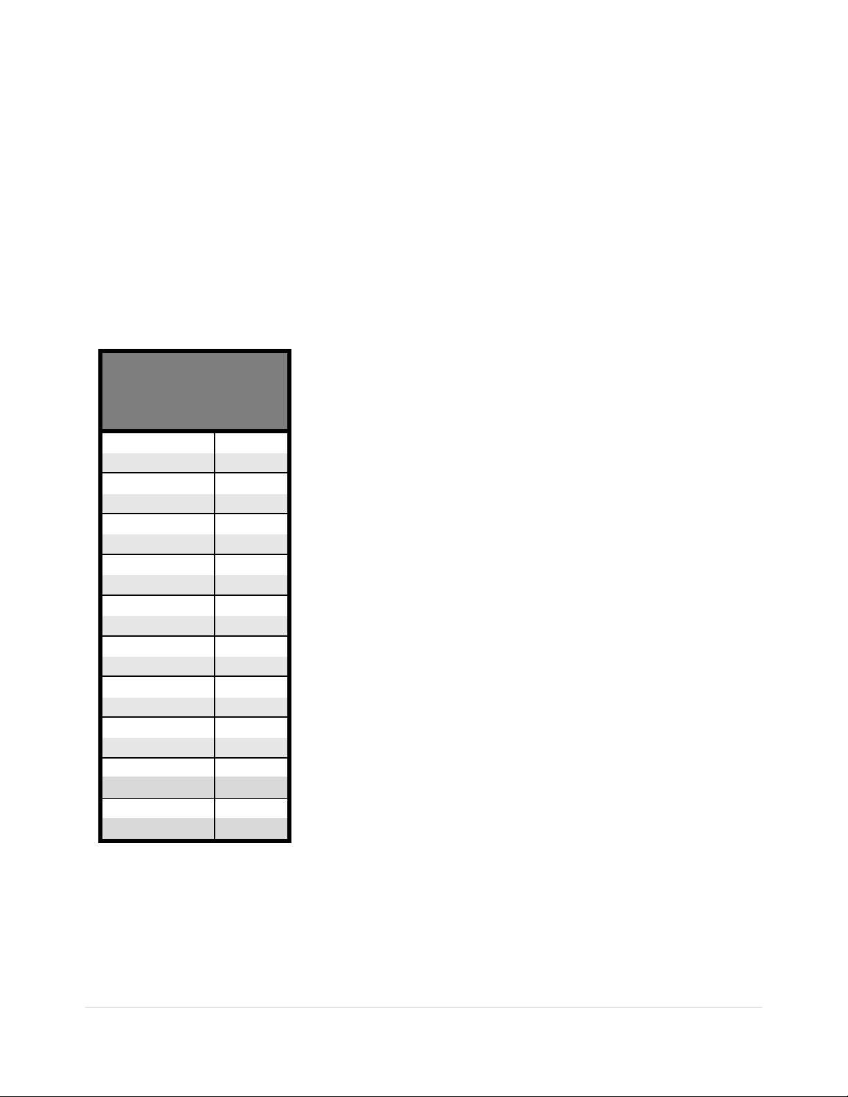
Sizes and Ratings
Model
Number
TE-18-BP
TE-28-BP
TE-39-BP
TE-48-BP
TE-62-BP
TE-78-BP
TE-92-BP
TE-112-BP
TE-150-BP
TE-160-BP
TE-210-BP
TE-275-BP
TE-361-BP
TE-450-BP
TE-550-BP
TE-600-BP
TE-862-BP
TE-900-BP
TE-1000-BP
TE-1250-BP
Table 1: TE Series selection
Start / Stop control. Programmable auxiliary contacts and provisions for interlocking are
Current
Range
Min. - Max.
9 - 18
14 - 28
19 - 39
24 - 48
36 - 62
39 - 78
46 - 92
56 - 112
75 - 150
80 - 160
105 - 210
137 - 275
180 - 361
225 - 450
275 - 550
300 - 600
431 - 862
450 - 900
503 - 1006
625 - 1250
The Toshiba TE Series starters are current rated controllers. Max.
Amp ratings are for continuous duty and must not be exceeded.
Always check the motor nameplate FLA and Service Factor (if used)
to ensure proper sizing. Each size has an adjustable range of current
from 50% to 100% of the Max Amp rating. Table 1 to the left shows
the Current Ratings available.
7|Page
 Loading...