

Page 1

TOSHIBA TE2000
Portable Personal Computer
User’s Manual
Page 2

Copyright
© 2001 by TOSHIBA Corporation. All rights reserved. Under the copyright laws,
this manual cannot be reproduced in any form without the prior written permission
of TOSHIBA. No patent liability is assumed, with respect to the use of the information contained herein.
TOSHIBA TE2000 Portable Personal Computer User’s Manual
First edition January 2002
Disclaimer
This manual has been validated and reviewed for accuracy. The instructions and
descriptions it contains are accurate for the TOSHIBA TE2000 Portable Personal
Computer at the time of this manual’s production. However, succeeding computers
and manuals are subject to change without notice. TOSHIBA assumes no liability
for damages incurred directly or indirectly from errors, omissions or discrepancies
between the computer and the manual.
Trademarks
IBM PC and PS/2 are trademarks of International Business Machines Corporation.
Intel and Pentium are registered trademarks, and Celeron and Intel SpeedStep are
trademarks of Intel Corporation.
Windows and Microsoft are registered trademarks of Microsoft Corporation.
Sound Blaster and Pro are trademarks of Creative Technology Ltd.
Photo CD is a trademark of Eastman Kodak.
Centronics is a registered trademark of Centronics Data Computer Corporation.
i.LINK is a trademark of Sony Corporation.
Other trademarks and registered trademarks not listed above may be used in this
manual.
Page 3
EU Declaration of Conformity
TOSHIBA declares, that the product: PS600* conforms to the following Standards:
Supplementary Information: “The product complies with the requirements
of the Low Voltage Directive 73/23/EEC, the
EMC Directive 89/336/EEC and/or the
R&TTE Directive 1999/05/EEC.”
This product is carrying the CE-Mark in accordance with the related European
Directives. Responsible for CE-Marking is TOSHIBA Europe, Hammfelddamm 8,
41460 Neuss, Germany.
VCCI Class B Information
Modem warning notice
Conformity Statement
The equipment has been approved to [Commission Decision “CTR21”] for panEuropean single terminal connection to the Public Switched Telephone Network
(PSTN).
However, due to differences between the individual PSTNs provided in different
countries/regions the approval does not, of itself, give an unconditional assurance of
successful operation on every PSTN network termination point.
In the event of problems, you should contact your equipment supplier in the first
instance.
Page 4

Network Compatibility Statement
This product is designed to work with, and is compatible with the following
networks. It has been tested to and found to conform with the additional requirements conditional in EG 201 121.
Germany ATAAB AN005,AN006,AN007,AN009,AN010 and
DE03,04,05,08,09,12,14,17
Greece ATAAB AN005,AN006 and GR01,02,03,04
Portugal ATAAB AN001,005,006,007,011 and P03,04,08,10
Spain ATAAB AN005,007,012, and ES01
Switzerland ATAAB AN002
All other countries/regions ATAAB AN003,004
Specific switch settings or software setup are required for each network, please refer
to the relevant sections of the user guide for more details.
The hookflash (timed break register recall) function is subject to separate national
type approvals. It has not been tested for conformity to national type regulations,
and no guarantee of successful operation of that specific function on specific
national networks can be given.
Japan regulations
Region selection
If you are using the computer in Japan, technical regulations described in the
Telecommunications Business Law require that you select the Japan region mode. It
is illegal to use the modem in Japan with any other selection.
Redial
Up to two redial attempts can be made. If more than two redial attempts are made,
the modem will return Black Listed. If you are experiencing problems with the
Black Listed code, set the interval between redials at one minute or longer.
Japan’s Telecommunications Business Law permits up to two redials on analogue
telephones, but the redials must be made within a total of three minutes.
The internal modem is approved by Japan Approvals Institute for Telecommunications
Equipment.
A00-0940JP
Page 5

Pursuant to FCC CFR 47, Part 68:
When you are ready to install or use the modem, call your local telephone company
and give them the following information:
❑ The telephone number of the line to which you will connect the modem
❑ The registration number that is located on the device
The FCC registration number of the modem will be found on either the device
which is to be installed, or, if already installed, on the bottom of the computer
outside of the main system label.
❑ The Ringer Equivalence Number (REN) of the modem, which can vary. For
the REN of your modem, refer to your modem’s label.
The modem connects to the telephone line by means of a standard jack called the
USOC RJ11C.
Type of service
Your modem is designed to be used on standard-device telephone lines. Connection to telephone company-provided coin service (central office implemented
systems) is prohibited. Connection to party lines service is subject to state tariffs. If
you have any questions about your telephone line, such as how many pieces of
equipment you can connect to it, the telephone company will provide this information upon request.
Telephone company procedures
The goal of the telephone company is to provide you with the best service it can. In
order to do this, it may occasionally be necessary for them to make changes in their
equipment, operations, or procedures. If these changes might affect your service or
the operation of your equipment, the telephone company will give you notice in
writing to allow you to make any changes necessary to maintain uninterrupted
service.
Page 6

If problems arise
If any of your telephone equipment is not operating properly, you should immediately remove it from your telephone line, as it may cause harm to the telephone
network. If the telephone company notes a problem, they may temporarily discontinue service. When practical, they will notify you in advance of this disconnection.
If advance notice is not feasible, you will be notified as soon as possible. When you
are notified, you will be given the opportunity to correct the problem and informed
of your right to file a complaint with the FCC. In the event repairs are ever needed
on your modem, they should be performed by TOSHIBA Corporation or an
authorized representative of TOSHIBA Corporation.
Disconnection
If you should ever decide to permanently disconnect your modem from its present
line, please call the telephone company and let them know of this change.
Fax branding
The Telephone Consumer Protection Act of 1991 makes it unlawful for any person
to use a computer or other electronic device to send any message via a telephone
fax machine unless such message clearly contains in a margin at the top or bottom
of each transmitted page or on the first page of the transmission, the date and time it
is sent and an identification of the business, other entity or individual sending the
message and the telephone number of the sending machine or such business, other
entity or individual. In order to program this information into your fax modem, you
should complete the setup of your fax software before sending messages.
Instructions for IC CS-03 certified equipment
1 The Industry Canada label identifies certified equipment. This certification
means that the equipment meets certain telecommunications network protective,
operational and safety requirements as prescribed in the appropriate Terminal
Equipment Technical Requirements document(s). The Department does not
guarantee the equipment will operate to the user’s satisfaction.
Before installing this equipment, users should ensure that it is permissible to be
connected to the facilities of the local telecommunications company. The
equipment must also be installed using an acceptable method of connection.
Page 7

The customer should be aware that compliance with the above conditions may
not prevent degradation of service in some situations. Repairs to certified
equipment should be coordinated by a representative designated by the supplier.
Any repairs or alterations made by the user to this equipment, or equipment
malfunctions, may give the telecommunications company cause to request the
user to disconnect the equipment.
Users should ensure for their own protection that the electrical ground connections of the power utility, telephone lines and internal metallic water pipe system,
if present, are connected together. This precaution may be particularly important
in rural areas.
CAUTION: Users should not attempt to make such connections
themselves, but should contact the appropriate electric inspection
authority, or electrician, as appropriate.
2 The user manual of analog equipment must contain the equipment’s Ringer
Equivalence Number (REN) and an explanation notice similar to the following:
The Ringer Equivalence Number (REN) of the modem, which can vary. For the
REN of your modem, refer to your modem’s label.
NOTICE: The Ringer Equivalence Number (REN) assigned to each
terminal device provides an indication of the maximum number of
terminals allowed to be connected to a telephone interface. The termination on an interface may consist of any combination of devices subject
only to the requirement that the sum of the Ringer Equivalence Numbers
of all the devices does not exceed 5.
3 The standard connecting arrangement (telephone jack type) for this equipment is
jack type(s): USOC RJ11C.
The IC registration number of the modem is shown below.
Canada: 1353 11026A
Page 8

Notes for Users in Australia and New Zealand
Modem warning notice for Australia
Modems connected to the Australian telecoms network must have a valid Austel
permit. This modem has been designed to specifically configure to ensure compliance with Austel standards when the country/region selection is set to Australia. The
use of other country/region setting while the modem is attached to the Australian
PSTN would result in you modem being operated in a non-compliant manner. To
verify that the country/region is correctly set, enter the command ATI which
displays the currently active setting.
To set the country/region permanently to Australia, enter the following command
sequence:
AT%TE=1
ATS133=1
A T&F
AT&W
AT%TE=0
ATZ
Failure to set the modem to the Australia country/region setting as shown above will
result in the modem being operated in a non-compliant manner. Consequently, there
would be no permit in force for this equipment and the Telecoms Act 1991
prescribes a penalty of $12,000 for the connection of non-permitted equipment.
Notes for use of this device in New Zealand
❑ The grant of a Telepermit for a device in no way indicates Telecom acceptance
of responsibility for the correct operation of that device under all operating
conditions. In particular the higher speeds at which this modem is capable of
operating depend on a specific network implementation which is only one of
many ways of delivering high quality voice telephony to customers. Failure to
operate should not be reported as a fault to Telecom.
❑ In addition to satisfactory line conditions a modem can only work properly if:
a/ it is compatible with the modem at the other end of the call and
b/ the application using the modem is compatible with the application at the
other end of the call - e.g., accessing the Internet requires suitable software
in addition to a modem.
❑ This equipment shall not be used in any manner which could constitute a
nuisance to other Telecom customers.
Page 9

❑ Some parameters required for compliance with Telecom’s PTC Specifications
are dependent on the equipment (PC) associated with this modem. The
associated equipment shall be set to operate within the following limits for
compliance with Telecom Specifications:
a/ There shall be no more than 10 call attempts to the same number within
any 30 minute period for any single manual call initiation, and
b/ The equipment shall go on-hook for a period of not less than 30 seconds
between the end of one attempt and the beginning of the next.
c/ Automatic calls to different numbers shall be not less than 5 seconds
apart.
❑ Immediately disconnect this equipment should it become physically damaged,
and arrange for its disposal or repair.
❑ The correct settings for use with this modem in New Zealand are as follows:
ATB0 (CCITT operation)
AT&G2 (1800 Hz guard tone)
AT&P1 (Decadic dialing make-break ratio =33%/67%)
ATS0=0 (not auto answer)
ATS10=less than 150 (loss of carrier to hangup delay, factory default of 15
recommended)
ATS11=90 (DTMF dialing on/off duration=90 ms)
ATX2 (Dial tone detect, but not (U.S.A.) call progress detect)
❑ When used in the Auto Answer mode, the S0 register must be set with a value
of 3 or 4. This ensures:
(a) a person calling your modem will hear a short burst of ringing before the
modem answers. This confirms that the call has been successfully
switched through the network.
(b) caller identification information (which occurs between the first and
second ring cadences) is not destroyed.
❑ The preferred method of dialing is to use DTMF tones (ATDT...) as this is
faster and more reliable than pulse (decadic) dialing. If for some reason you
must use decadic dialing, your communications program must be set up to
record numbers using the following translation table as this modem does not
implement the New Zealand “Reverse Dialing” standard.
Number to be dialed: 0 1 2 3 4 5 6 7 8 9
Number to program into computer: 0 9 8 7 6 5 4 3 2 1
Note that where DTMF dialing is used, the numbers should be entered
normally.
Page 10

❑ The transmit level from this device is set at a fixed level and because of this
there may be circumstances where the performance is less than optimal. Before
reporting such occurrences as faults, please check the line with a standard
Telepermitted telephone, and only report a fault if the phone performance is
impaired.
❑ It is recommended that this equipment be disconnected from the Telecom line
during electrical storms.
❑ When relocating the equipment, always disconnect the Telecom line connec-
tion before the power connection, and reconnect the power first.
❑ This equipment may not be compatible with Telecom Distinctive Alert
cadences and services such as FaxAbility.
NOTE THAT FAULT CALLOUTS CAUSED BY ANY OF THE
ABOVE CAUSES MAY INCUR A CHARGE FROM TELECOM
General conditions
As required by PTC 100, please ensure that this office is advised of any changes to
the specifications of these products which might affect compliance with the relevant
PTC Specifications.
The grant of this Telepermit is specific to the above products with the marketing
description as stated on the Telepermit label artwork. The Telepermit may not be
assigned to other parties or other products without Telecom approval.
A Telepermit artwork for each device is included from which you may prepare any
number of Telepermit labels subject to the general instructions on format, size and
colour on the attached sheet.
The Telepermit label must be displayed on the product at all times as proof to
purchasers and service personnel that the product is able to be legitimately connected to the Telecom network.
The Telepermit label may also be shown on the packaging of the product and in the
sales literature, as required in PTC 100.
The charge for a Telepermit assessment is $337.50. An additional charge of $337.
50 is payable where an assessment is based on reports against non-Telecom New
Zealand Specifications. $112.50 is charged for each variation when submitted at
the same time as the original.
An invoice for $NZ1237.50 will be sent under separate cover.
Page 11

Information to Wireless LAN User
Wireless Interoperability
The TOSHIBA Wireless LAN Mini PCI Card products are designed to be
interoperable with any Wireless LAN product that is based on Direct Sequence
Spread Spectrum (DSSS) radio technology, and is compliant to:
❑ The IEEE 802.11 Standard on Wireless LANs (Revision B), as defined and
approved by the Institute of Electrical and Electronics Engineers.
❑ The Wireless Fidelity (WiFi) certification as defined by the WECA Wireless
Ethernet Compatibility Alliance.
Wireless LAN and your Health
Wireless LAN products, like other radio devices, emit radio frequency electromagnetic energy. The level of energy emitted by Wireless LAN devices however is far
much less than the electromagnetic energy emitted by wireless devices like for
example mobile phones.
Because Wireless LAN products operate within the guidelines found in radio
frequency safety standards and recommendations, TOSHIBA believes Wireless
LAN is safe for use by consumers. These standards and recommendations reflect
the consensus of the scientific community and result from deliberations of panels
and committees of scientists who continually review and interpret the extensive
research literature.
In some situations or environments, the use of Wireless LAN may be restricted by
the proprietor of the building or responsible representatives of the organization.
These situations may for example include:
❑ Using the Wireless LAN equipment on board of airplanes, or
❑ In any other environment where the risk of interference to other devices or
services is perceived or identified as harmful.
If you are uncertain of the policy that applies on the use of wireless devices in a
specific organization or environment (e.g. airports), you are encouraged to ask for
authorization to use the Wireless LAN device prior to turning on the equipment.
Regulatory Information
The TOSHIBA Wireless LAN Mini PCI Card must be installed and used in strict
accordance with the manufacturer’s instructions as described in the user documentation that comes with the product. This device complies with the following radio
frequency and safety standards.
Page 12

Canada – Industry Canada (IC)
This device complies with RSS 210 of Industry Canada.
Operation is subject to the following two conditions: (1) this device may not cause
interference, and (2) this device must accept any interference, including interference
that may cause undesired operation of this device.”
L’utilisation de ce dispositif est autorisée seulement aux conditions suivantes : (1) il
ne doit pas produire de brouillage et (2) l’utilisateur du dispositif doit étre prét à
accepter tout brouillage radioélectrique reçu, même si ce brouillage est susceptible
de compromettre le fonctionnement du dispositif.
Europe – EU Declaration of Conformity
This device complies with the essential requirements of the R&TTE Directive
1999/5/EC with essential test suites as per standards:
❑ EN 60950 Safety of Information Technology equipment
❑ ETS 300 328 Technical requirements for radio equipment
❑ ETS 300 826 General EMC requirements for radio equipment.
België/ For outdoor usage only channel 10 (2457 MHz) and 11 (2462
Belgique: MHz) is allowed.
For private usage outside buildings across public grounds over
less than 300m no special registration with IBPT/BIPT is
required. Registration to IBPT/BIPT is required for private usage
outside buildings across public grounds over more than 300m.
An IBPT/BIPT license is required for public usage outside
building.
For registration and license please contact IBPT/BIPT.
Gebruik buiten gebouw alleen op kanalen 10 (2457 MHz) en 11
(2462 MHz). Voor privé-gebruik buiten gebouw over publieke
groud over afstand kleiner dan 300m geen registratie bij BIPT/
IBPT nodig; voor gebruik over afstand groter dan 300m is wel
registratie bij BIPT/IBPT nodig. Voor publiek gebruik buiten
gebouwen is licentie van BIPT/IBPT verplicht. Voor registratie of
licentie kunt u contact opnemen met BIPT.
Page 13

L’utilisation en extérieur est autorisé sur le canal 10 (2457 MHz)
et 11 (2462 MHz).
Dans le cas d’une utilisation privée, à l’extérieur d’un bâtiment,
au-dessus d’un espace public, aucun enregistrement n’est
nécessaire pour une distance de moins de 300m. Pour une
distance supérieure à 300m un enregistrement auprès de I’IBPT
est requise. Pour une utilisation publique à I’extérieur de
bâtiments, une licence de I’IBPT est requise. Pour les
enregistrements et licences, veuillez contacter I’IBPT.
Deutschland: License required for outdoor installations. Check with reseller
for procedure to follow
Anmeldung im Outdoor-Bereich notwendig, aber nicht
genehmigungspflichtig. Bitte mit Händler die Vorgehensweise
abstimmen.
France: Restricted frequency band: only channels 10 and 11 (2457 MHz
and 2462 MHz respectively) may be used in France. License
required for every installation, indoor and outdoor installations.
Please contact ART for procedure to follow.
Bande de fréquence restreinte : seuls les canaux 10 à 11 (2457
et 2462 MHz respectivement) doivent être utilisés en France.
Toute utilisation, qu’elle soit intérieure ou extérieure, est
soumise à autorisation. Vous pouvez contacter I’Autorité de
Régulation des Télécommuniations (http://www.art-telecom.fr)
pour la procédure à suivre.
Italia: License required for indoor use. Use with outdoor installations
not allowed
E’necessaria la concessione ministeriale anche per l’uso
interno.
Verificare con i rivenditori la procedura da seguire. L’uso per
installazione in esterni non e’ permessa.
Nederland License required for outdoor installations. Check with reseller
for procedure to follow
Licentie verplicht voor gebruik met buitenantennes. Neem
contact op met verkoper voor juiste procedure
Page 14

USA-Federal Communications Commission(FCC)
This device complies with Part 15 of FCC Rules. Operation of the devices in a
Wireless LAN System is subject to the following two conditions:
❑ This device may not cause harmful interference.
❑ This device must accept any interference that may cause undesired operation.
Caution: Exposure to Radio Frequency Radiation.
The radiated output power of the TOSHIBA Wireless LAN Mini PCI Card is far
below the FCC radio frequency exposure limits. Nevertheless, the TOSHIBA
Wireless LAN Mini PCI Card shall be used in such a manner that the potential for
human contact during normal operation is minimized. When using this device in
combination with Wireless LAN Outdoor Antenna products, a certain separation
distance between antenna and nearby persons has to be kept to ensure RF exposure
compliance. The distance between the antennas and the user should not be less than
5.0cm.
Refer to the Regulatory Statements as identified in the documentation that comes
with those products for additional information.
The TOSHIBA Wireless LAN Mini PCI Card is far below the FCC radio frequency
exposure limits.
Nevertheless, it is advised to use the TOSHIBA Wireless LAN Mini PCI Card in
such a manner that human contact during normal operation is minimized.
Interference Statement
This equipment has been tested and found to comply with the limits for a Class B
digital device, pursuant to Part 15 of the FCC Rules. These limits are designed to
provide reasonable protection against harmful interference in a residential
installation.
This equipment generates, uses, and can radiate radio frequency energy. If not
installed and used in accordance with the instructions, it may cause harmful
interference to radio communications. However, there is no guarantee that interference will not occur in a particular installation.
If this equipment does cause harmful interference to radio or television reception,
which can be determined by turning the equipment off and on, the user is encouraged to try and correct the interference by one or more of the following measures:
❑ Reorient or relocate the receiving antenna.
❑ Increase the distance between the equipment and the receiver.
Page 15

❑ Connect the equipment to an outlet on a circuit different from that to which the
receiver is connected.
❑ Consult the dealer or an experienced radio/TV technician for help.
TOSHIBA is not responsible for any radio or television interference caused by
unauthorized modification of the devices included with this TOSHIBA Wireless
LAN Mini PCI Card, or the substitution or attachment of connecting cables and
equipment other than specified by TOSHIBA .
The correction of interference caused by such unauthorized modification, substitution or attachment will be the responsibility of the user.
Taiwan
Article 14 Unless approved, for any model accredited low power radio
frequency electric machinery, any company, trader or user shall
not change the frequency, increase the power or change the
features and functions of the original design.
Article 17 Any use of low power radio frequency electric machinery shall
not affect the aviation safety and interfere with legal
communications. In event that any interference is found, the use
of such electric machinery shall be stopped immediately, and
reusing of such products can be resumed until no interference
occurs after improvement.
The legal communications mentioned in the above item refer to
radio communications operated in accordance with
telecommunication laws and regulations.
Low power radio frequency electric machinery shall resist
against interference from legal communications or from
industrial, scientific and medical radio emission electric
machinery.
Using this equipment in Japan
In Japan, the frequency bandwidth of 2,400~2,483.5MHz for second generation
low-power data communication systems such as this equipment overlaps that of
mobile object identification systems (premises radio station and specified lowpower radio station).
Page 16
1. Sticker
Please put the following sticker on devices incorporating this product.
In the frequency bandwidth of this equipment, industrial device,
scientific device, medical device like microwave oven, licensed
premises radio station and non-licensed specified low-power
radio station for mobile object identification system (RF-ID) that
is used in product line of factories, (Other Radio Stations)are
used.
1 Please make sure before using this equipment that no Other
Radio Stations are used in the neighborhood.
2 In case that RF interference occurs to Other Radio Stations
from this equipment, please change promptly the frequency for
use, place to use, or stop emitting Radio.
3 Please contact TOSHIBA Direct PC if you have a problem,
such as interference from this equipment to Other Radio
Stations.
2. Indication
The indication shown below appears on this equipment.
(1) (2) (3)
2.4 DS 4
(4)
(1) 2.4 :This equipment uses a frequency of 2.4GHz.
(2) DS:This equipment uses DS-SS modulation.
(3) 4 : The interference range of this equipment is less than 40m.
(4) : This equipment uses a frequency bandwidth from 2,
400MHz to 2,483.5MHz.
It is possible to avoid the band of mobile object identifica-
tion systems.
Page 17

3. TOSHIBA Direct PC
Monday — Friday : 10:00 — 17:00
Toll Free Tel : 0120-13-1100
Direct Dial : 03-3457-5916
FAX : 03-5444-9450
Electronic communication device authorization
This device obtains the Technical Conditions Compliance Approval, and it belongs
to the device class of radio equipment of low-power data communication system
radio station stipulated in the Telecommunications Business Law.
The following restrictions apply:
❑ Do not disassemble or modify the device.
❑ Do not remove the authorization label from the device.
Device Authorization
This device obtains the Technical Regulation Conformity Certification, and it
belongs to the device class of radio equipment of low-power data communication
system radio station stipulated in the Radio Law of Japan.
The following restrictions apply:
❑ Do not disassemble of modify the device.
❑ Do not remove the authorization label from the device.
Regulatory statements
General
This product complies with any mandatory product specification in any country/
region where the product is sold. In addition, the product complies with the
following.
European Union (EU) and EFTA
This equipment complies with the R&TTE directive 1999/5/EC and has been
provided with the CE mark accordingly.
Page 18

United States of America and Canada
Tested To Comply With FCC Standards FOR HOME OR OFFICE USE. See FCC
47CFR part 15.19(b)(2)
This device complies with part15 of the FCC rules and with RSS-210 / RSS-139 of
the Industry Canada. Operation is subject to the following two conditions: (1) This
device may not cause harmful interference, and (2) this device must accept any
interference received, including interference that may cause undesired operation.
Note that any changes or modifications to this equipment not expressly approved by
the manufacturer may void the FCC authorization to operate this equipment.
Canada
IC Notice
To prevent radio interference to the licensed service, this device is intended to be
operated indoors and away from windows to provide maximum shielding. Equipment that is installed outdoors is subject to licensing.
Pour empêcher un brouillage radioélectrique au service faisant l’objet d’une
licence, cet appareil doit être utilisé à l’interieur et loin des fenêtres afin de founir
un écran de blindage maximal. Au cas aù un installation en plain air, le materiel doit
faire l’objet d’une licence.
Caution
FCC Interference Statement
Tested to comply with FCC Standards FOR HOME OR OFFICE USE. See FCC
47CFR part 15.19(b)(2). This device complies with part15 of the FCC rules and
with RSS-210 / RSS-139 of the Industry Canada. Operation is subject to the
following to conditions:
❑ This device may not cause harmful interference, and
❑ This device must accept any interference received, including interference that
may cause undesired operation.
This equipment has been tested and found to comply with the limits for a Class B
digital device, pursuant to Part 15 of the FCC Rules. These limits are designed to
provide reasonable protection against harmful interference in a residential
installation.
Page 19

This equipment generates, uses and can radiate radio frequency energy and, if not
installed and used in accordance with the instructions, may cause harmful interference to radio communications. However, there is no guarantee that interference will
not occur in a particular installation.
If this equipment does cause harmful interference to radio or television reception,
which can be determined by turning the equipment off and on, the user is encouraged to try and correct the interference by one or more of the following measures:
❑ Reorient or relocate the receiving antenna.
❑ Increase the separation between the equipment and the receiver.
❑ Connect the equipment into an outlet on a circuit different from that to which
the receiver is connected.
❑ Consult the dealer or an experienced radio/TV technician for help.
Note that any changes or modifications to this equipment not expressly approved by
the manufacturer may void the authorization to operate this equipment.
Page 20
TOSHIBA DVD-ROM drive SD-C2502** safety instruction
** means any letters or numbers.
CAUTIONS:1. The DVD-ROM drive employs a laser system. To ensure
proper use of this product, please read this instruction
manual carefully and retain for future reference. Should
the unit ever require maintenance, contact an authorized
service location.
2. Use of controls, adjustments or the performance of
procedures other than those specified may result in
hazardous radiation exposure.
3. To prevent direct exposure to the laser beam, do not try
to open the enclosure.
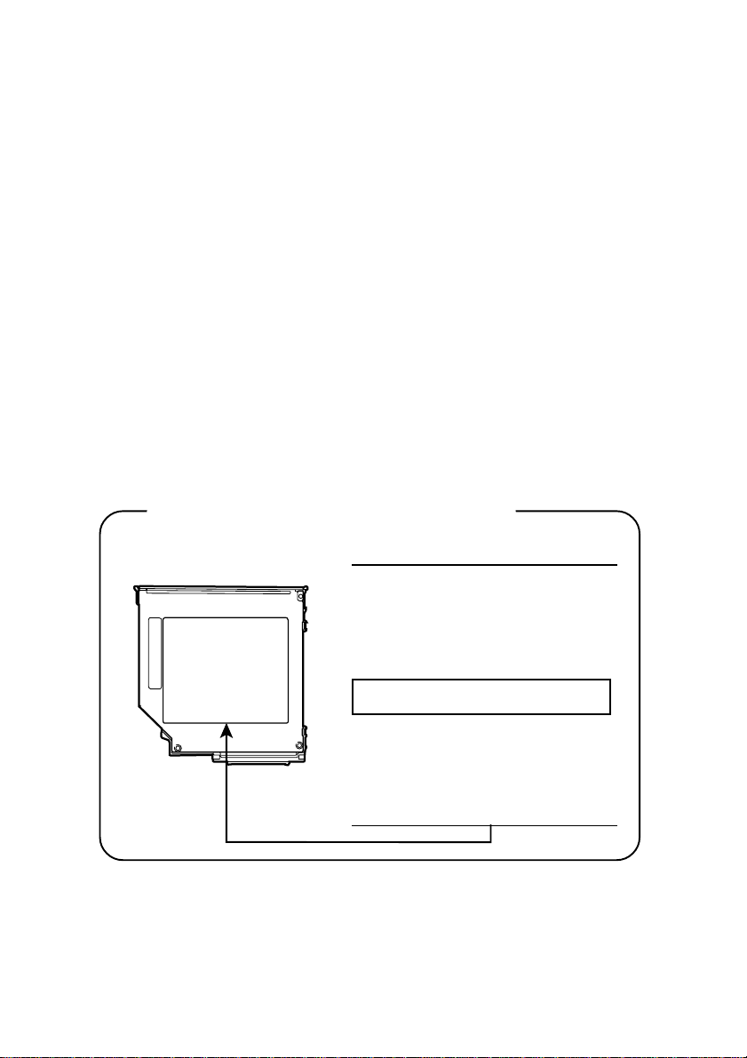
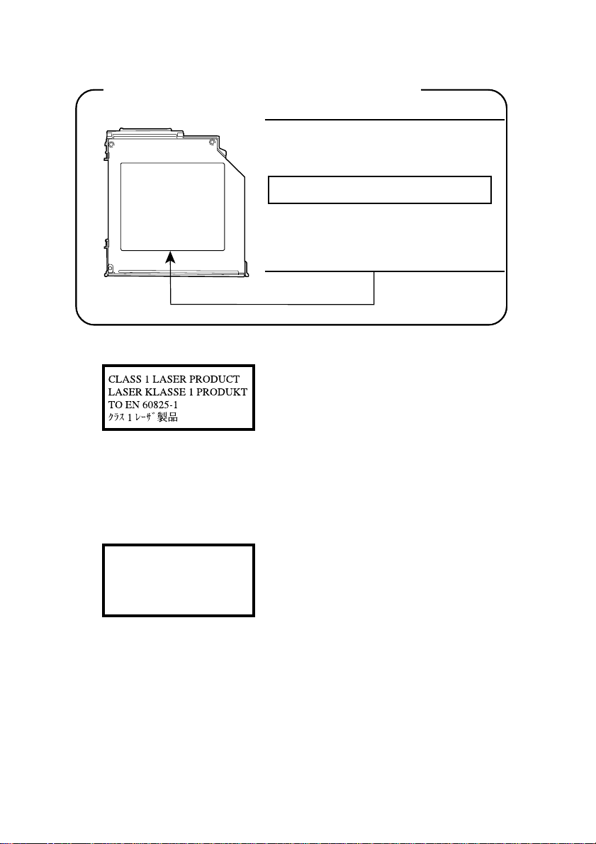
Location of the required label
PRODUCT IS CERTIFIED BY THE
MANUFACTURER TO COMPLY
WITH DHHS RULES 21 CFR
SUBCHAPTER J APPLICABLE AT
THE DATE OF MANUF ACTURE.
MANUFACTURED:
TOSHIBA CORPORATION
1-1, SHIBAURA 1-CHOME
MINAT O-KU, T OKYO 105-8001,
JAPAN
Page 21
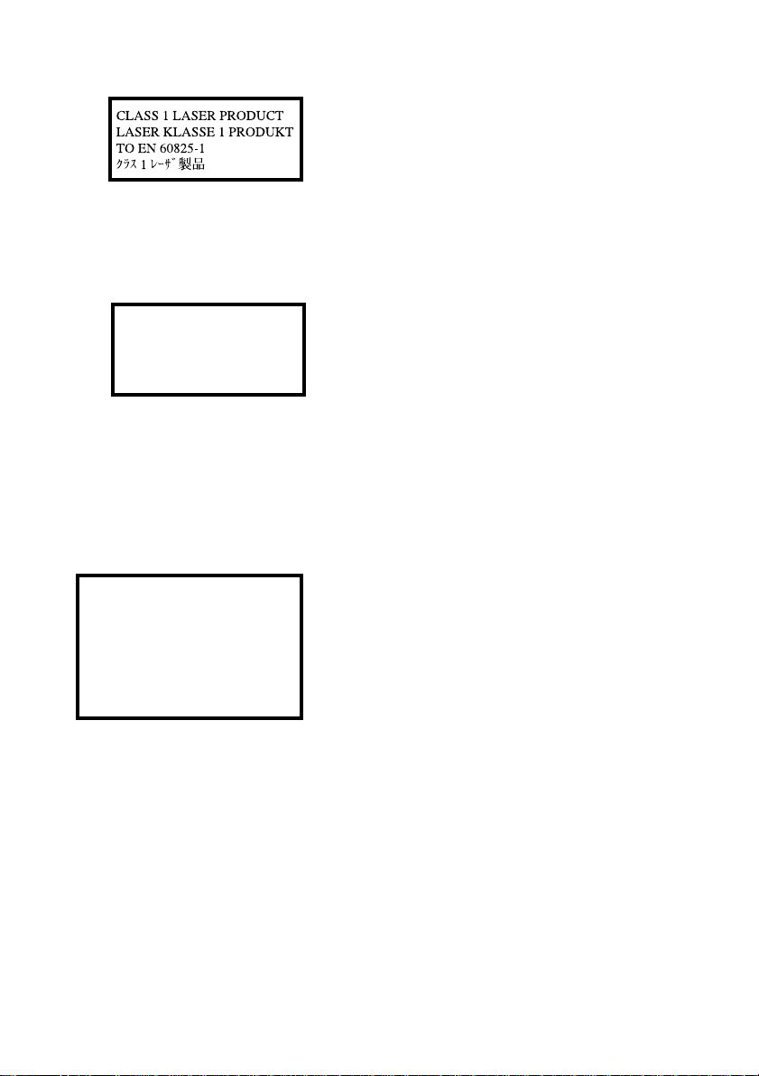
CAUTION: This appliance contains a laser
system and is classified as a “CLASS 1 LASER
PRODUCT.” To use this model properly, read
the instruction manual carefully and keep this
manual for your future reference. In case of any
trouble with this model, please contact your
nearest “AUTHORIZED service station.” To
prevent direct exposure to the laser beam, do not
try to open the enclosure.
CLASS 1 LASER PRODUCT
LASERSCHUTZKLASSE 1
PRODUKT
TO EN60825
ADVERSEL: USYNLIG
LASERSTRÅLING VED ÅBNING,
NÅR SIKKERHEDSAF-BRYDER ER
UDE AF FUNKTION.
UNDGÅ UDSÆTTELSE FOR
STRÅLING
VORSICHT: Dieses Gerät enthält ein La serSystem und ist als “LASERSCHUTZKLASSE 1
PRODUKT” klassifiziert. Für den richtigen
Gebrauch dieses Modells lesen Sie bitte die
Bedienungsanleitung sorgfältig durch und
bewahren diese bitte als Referenz auf. Falls
Probleme mit diesem Modell auftreten,
benachrichtigen Sie bitte die nächste
“autorisierte Service-Vertretung”. Um einen
direkten Kontakt mit dem Laserstrahl zu
vermeiden darf das Gerät nicht geöffnet
werden.
ADVARSEL: Denne mærking er anbragt
udvendigt på apparatet og indikerer, at
apparatet arbejder med laserstråler af klasse 1,
hviket betyder, at der anvendes laserstrlier af
svageste klasse, og at man ikke på apparatets
yderside kan bilve udsat for utilladellg kraftig
stråling.
APPARATET BOR KUN ÅBNES AF FAGFOLK
MED SÆRLIGT KENDSKAB TIL APPARATER
MED LASERSTRÅLER!
Indvendigt i apparatet er anbragt den her
gengivne advarselsmækning, som advarer imod
at foretage sådanne indgreb i apparatet, at man
kan komme til at udsætte sig for laserstråling.
OBS! Apparaten innehåller laserkomponent som
avger laserstråining överstigande gränsen för
laserklass 1.
Page 22

VAROITUS. Suojakoteloa si saa avata. Laite
sisältää laserdiodin, joka lähetää näkymätöntä
silmilie vaarallista lasersäteilyä.
CAUTION: USE OF CONTROLS OR ADJUSTMENTS OR PERFORMANCE OF PROCEDURES OTHER THAN THOSE SPECIFIED IN
THE OWNER’S MANUAL MAY RESULT IN
HAZARDOUS RADIATION EXPOSURE.
VORSICHT: DIE VERWENDUNG VON
ANDEREN STEURUNGEN ODER
EINSTELLUNGEN ODER DAS
DURCHFÜHREN VON ANDEREN
VORGÄNGEN ALS IN DER
BEDIENUNGSANLEITUNG BESCHRIEBEN
KÖNNEN GEFÄHRLICHE
STRAHLENEXPOSITIONEN ZUR FOLGE
HABEN.
Matsushita CD-R/RW drive UJDA340** safety instruction
** means any letters or numbers.
CAUTIONS:1. The CD-R/RW drive employs a laser system. To ensure
proper use of this product, please read this instruction
manual carefully and retain for future reference. Should
the unit ever require maintenance, contact an authorized
service location.
2. Use of controls, adjustments or the performance of
procedures other than those specified may result in
hazardous radiation exposure.
3. To prevent direct exposure to the laser beam, do not try
to open the enclosure.
Page 23
Location of the required label
Location of the required label
COMPLIES WITH FDA RADIA TION
PERFORMANCE STANDAR DS, 21 CFR
SUBCHAPTER J.
MANUFACTURED:
Manufactured by
Kyushu Matsushita Electric Co., Ltd.
1-62 4-Chome Minoshima, Hakata-Ku
Fukuoka,Japan
CAUTION: This appliance contains a laser
system and is classified as a “CLASS 1
LASER PRODUCT.” To use this model
properly, read the instruction manual
carefully and keep this manual for your future
reference. In case of any trouble with this
model, please contact your nearest “AUTHORIZED service station.” To prevent direct
exposure to the laser beam, do not try to open
the enclosure.
CLASS 1 LASER PRODUCT
LASERSCHUTZKLASSE 1
PRODUKT
TO EN60825
VORSICHT: Dieses Gerät enthält ein
Laser-System und ist als
“LASERSCHUTZKLASSE 1 PRODUKT”
klassifiziert. Für den richtigen Gebrauch
dieses Modells lesen Sie bitte die
Bedienungsanleitung sorgfältig durch und
bewahren diese bitte als Referenz auf. Falls
Probleme mit diesem Modell auftreten,
benachrichtigen Sie bitte die nächste
“autorisierte Service-Vertretung”. Um einen
direkten Kontakt mit dem Laserstrahl zu
vermeiden darf das Gerät nicht geöffnet
werden.
Page 24

ADVERSEL: USYNLIG
LASERSTRÅLING VED ÅBNING,
NÅR SIKKERHEDSAF-BRYDER ER
UDE AF FUNKTION.
UNDGÅ UDSÆTTELSE FOR
STRÅLING
ADVARSEL: Denne mærking er anbragt
udvendigt på apparatet og indikerer, at
apparatet arbejder med laserstråler af klasse 1,
hviket betyder, at der anvendes laserstrlier af
svageste klasse, og at man ikke på apparatets
yderside kan bilve udsat for utilladellg kraftig
stråling.
APPARATET BOR KUN ÅBNES AF FAGFOLK
MED SÆRLIGT KENDSKAB TIL APPARATER
MED LASERSTRÅLER!
Indvendigt i apparatet er anbragt den her
gengivne advarselsmækning, som advarer imod
at foretage sådanne indgreb i apparatet, at man
kan komme til at udsætte sig for laserstråling.
OBS! Apparaten innehåller laserkomponent som
avger laserstråining överstigande gränsen för
laserklass 1.
VAROITUS. Suojakoteloa si saa avata. Laite
sisältää laserdiodin, joka lähetää näkymätöntä
silmilie vaarallista lasersäteilyä.
CAUTION: USE OF CONTROLS OR ADJUSTMENTS OR PERFORMANCE OF PROCEDURES OTHER THAN THOSE SPECIFIED IN
THE OWNER’S MANUAL MAY RESULT IN
HAZARDOUS RADIATION EXPOSURE.
VORSICHT: DIE VERWENDUNG VON
ANDEREN STEURUNGEN ODER
EINSTELLUNGEN ODER DAS
DURCHFÜHREN VON ANDEREN
VORGÄNGEN ALS IN DER
BEDIENUNGSANLEITUNG BESCHRIEBEN
KÖNNEN GEFÄHRLICHE
STRAHLENEXPOSITIONEN ZUR FOLGE
HABEN.
Page 25

Matsushita CD-RW/DVD-ROM drive UJDA720** safety instruction
** means any letters or numbers.
CAUTIONS:1. The CD-RW/DVD-ROM drive employs a laser system.
To ensure proper use of this product, please read this
instruction manual carefully and retain for future
reference. Should the unit ever require maintenance,
contact an authorized service location.
2. Use of controls, adjustments or the performance of
procedures other than those specified may result in
hazardous radiation exposure.
3. To prevent direct exposure to the laser beam, do not try
to open the enclosure.
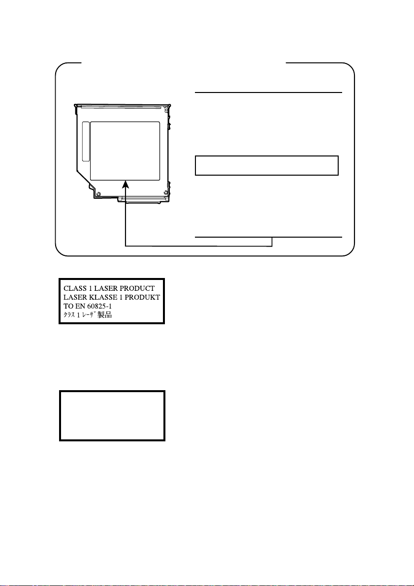
Location of the required label
Location of the required label
COMPLIES WITH FDA RADIA TION
PERFORMANCE STANDAR DS, 21 CFR
SUBCHAPTER J.
MANUFACTURED:
Manufactured by
Kyushu Matsushita Electric Co., Ltd.
1-62 4-Chome Minoshima, Hakata-Ku
Fukuoka,Japan
Page 26
CAUTION: This appliance contains a laser
system and is classified as a “CLASS 1 LASER
PRODUCT.” To use this model properly, read
the instruction manual carefully and keep this
manual for your future reference. In case of any
trouble with this model, please contact your
nearest “AUTHORIZED service station.” To
prevent direct exposure to the laser beam, do not
try to open the enclosure.
CLASS 1 LASER PRODUCT
LASERSCHUTZKLASSE 1
PRODUKT
TO EN60825
ADVERSEL: USYNLIG
LASERSTRÅLING VED ÅBNING,
NÅR SIKKERHEDSAF-BRYDER ER
UDE AF FUNKTION.
UNDGÅ UDSÆTTELSE FOR
STRÅLING
VORSICHT: Dieses Gerät enthält ein LaserSystem und ist als “LASERSCHUTZKLASSE 1
PRODUKT” klassifiziert. Für den richtigen
Gebrauch dieses Modells lesen Sie bitte die
Bedienungsanleitung sorgfältig durch und
bewahren diese bitte als Referenz auf. Falls
Probleme mit diesem Modell auftreten,
benachrichtigen Sie bitte die nächste
“autorisierte Service-Vertretung”. Um einen
direkten Kontakt mit dem Laserstrahl zu
vermeiden darf das Gerät nicht geöffnet
werden.
ADVARSEL: Denne mærking er anbragt
udvendigt på apparatet og indikerer, at
apparatet arbejder med laserstråler af klasse 1,
hviket betyder, at der anvendes laserstrlier af
svageste klasse, og at man ikke på apparatets
yderside kan bilve udsat for utilladellg kraftig
stråling.
APPARATET BOR KUN ÅBNES AF FAGFOLK
MED SÆRLIGT KENDSKAB TIL APPARATER
MED LASERSTRÅLER!
Indvendigt i apparatet er anbragt den her
gengivne advarselsmækning, som advarer imod
at foretage sådanne indgreb i apparatet, at man
kan komme til at udsætte sig for laserstråling.
OBS! Apparaten innehåller laserkomponent som
avger laserstråining överstigande gränsen för
laserklass 1.
Page 27

VAROITUS. Suojakoteloa si saa avata. Laite
sisältää laserdiodin, joka lähetää näkymätöntä
silmilie vaarallista lasersäteilyä.
CAUTION: USE OF CONTROLS OR ADJUSTMENTS OR PERFORMANCE OF PROCEDURES OTHER THAN THOSE SPECIFIED IN
THE OWNER’S MANUAL MAY RESULT IN
HAZARDOUS RADIATION EXPOSURE.
VORSICHT: DIE VERWENDUNG VON
ANDEREN STEURUNGEN ODER
EINSTELLUNGEN ODER DAS
DURCHFÜHREN VON ANDEREN
VORGÄNGEN ALS IN DER
BEDIENUNGSANLEITUNG BESCHRIEBEN
KÖNNEN GEFÄHRLICHE
STRAHLENEXPOSITIONEN ZUR FOLGE
HABEN.
TOSHIBA CD-RW/DVD-ROM drive SD-R2102** safety instruction
** means any letters or numbers.
CAUTIONS:1. The CD-RW/DVD-ROM drive employs a laser system.
To ensure proper use of this product, please read this
instruction manual carefully and retain for future
reference. Should the unit ever require maintenance,
contact an authorized service location.
2. Use of controls, adjustments or the performance of
procedures other than those specified may result in
hazardous radiation exposure.
3. To prevent direct exposure to the laser beam, do not try
to open the enclosure.
Page 28
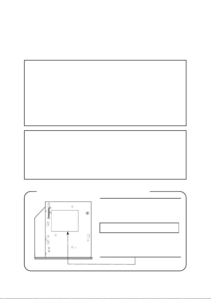
Location of the required label
PRODUCT IS CERTIFIED BY THE
MANUFACTURER TO COMPLY
WITH DHHS RULES 21 CFR
SUBCHAPTER J APPLICABLE AT
THE DATE OF MANUF ACTURE.
MANUFACTURED:
TOSHIBA CORPORATION
1-1, SHIBAURA 1-CHOME
MINAT O-KU, T OKYO 105-8001,
JAPAN
CAUTION: This appliance contains a laser
system and is classified as a “CLASS 1 LASER
PRODUCT.” To use this model properly, read
the instruction manual carefully and keep this
manual for your future reference. In case of any
trouble with this model, please contact your
nearest “AUTHORIZED service station.” To
prevent direct exposure to the laser beam, do not
try to open the enclosure.
CLASS 1 LASER PRODUCT
LASERSCHUTZKLASSE 1
PRODUKT
TO EN60825
VORSICHT: Dieses Gerät enthält ein La serSystem und ist als “LASERSCHUTZKLASSE 1
PRODUKT” klassifiziert. Für den richtigen
Gebrauch dieses Modells lesen Sie bitte die
Bedienungsanleitung sorgfältig durch und
bewahren diese bitte als Referenz auf. Falls
Probleme mit diesem Modell auftreten,
benachrichtigen Sie bitte die nächste
“autorisierte Service-Vertretung”. Um einen
direkten Kontakt mit dem Laserstrahl zu
vermeiden darf das Gerät nicht geöffnet
werden.
Page 29

ADVERSEL: USYNLIG
LASERSTRÅLING VED ÅBNING,
NÅR SIKKERHEDSAF-BRYDER ER
UDE AF FUNKTION.
UNDGÅ UDSÆTTELSE FOR
STRÅLING
ADVARSEL: Denne mærking er anbragt
udvendigt på apparatet og indikerer, at
apparatet arbejder med laserstråler af klasse
1, hviket betyder, at der anvendes laserstrlier
af svageste klasse, og at man ikke på
apparatets yderside kan bilve udsat for
utilladellg kraftig stråling.
APPARATET BOR KUN ÅBNES AF
FAGFOLK MED SÆRLIGT KENDSKAB TIL
APPARATER MED LASERSTRÅLER!
Indvendigt i apparatet er anbragt den her
gengivne advarselsmækning, som advarer
imod at foretage sådanne indgreb i apparatet,
at man kan komme til at udsætte sig for
laserstråling.
OBS! Apparaten innehåller laserkomponent
som avger laserstråining överstigande
gränsen för laserklass 1.
VAROITUS. Suojakoteloa si saa avata. Laite
sisältää laserdiodin, joka lähetää
näkymätöntä silmilie vaarallista lasersäteilyä.
CAUTION: USE OF CONTROLS OR
ADJUSTMENTS OR PERFORMANCE OF
PROCEDURES OTHER THAN THOSE
SPECIFIED IN THE OWNER’S MANUAL
MAY RESULT IN HAZARDOUS RADIATION EXPOSURE.
VORSICHT: DIE VERWENDUNG VON
ANDEREN STEURUNGEN ODER
EINSTELLUNGEN ODER DAS
DURCHFÜHREN VON ANDEREN
VORGÄNGEN ALS IN DER
BEDIENUNGSANLEITUNG BESCHRIEBEN
KÖNNEN GEFÄHRLICHE
STRAHLENEXPOSITIONEN ZUR FOLGE
HABEN.
Page 30
TEAC D VD-ROM drive D V-28E** safety instruction
** means any letters or numbers.
This product has been designed and manufactured according to FDA
regulations "title 21. CFR. chapter 1, subchapter J. based on the
radiation Control for Health and Safety Act of 1968," and is classified
as a class 1 laser product. There is no hazardous invisible laser
radiation confined in the protective housings.
The label required in this regulation is shown below.
CAUTION
Use of controls or adjustments or performance of procedures other than
those specified herein may result in hazardous radiation exposure.
Optical pickup
Type : PU-2200
Manufacturer : TEAC CORPORATION
Laser output : Less than 0.25m W on the objective
lens
Wavelength : 795nm.
Location of the required label
THIS PRODUCT COMPLIES WITH
DHHS RULES 21 CFR CHAPTER 1,
SUBCHAPTER J APPLICABLE AT
DATE OF MANUFACTURE.
MANUFACTURED:
Manufactured by
TEAC Corporation
3-7-3 Naka-cho, Musashino-shi, Tokyo,
Japan
Page 31

CAUTION: This appliance contains a laser
system and is classified as a “CLASS 1
LASER PRODUCT.” To use this model
properly, read the instruction manual
carefully and keep this manual for your future
reference. In case of any trouble with this
model, please contact your nearest “AUTHORIZED service station.” To prevent direct
exposure to the laser beam, do not try to open
the enclosure.
CLASS 1 LASER PRODUCT
LASERSCHUTZKLASSE 1
PRODUKT
TO EN60825
ADVERSEL: USYNLIG
LASERSTRÅLING VED ÅBNING,
NÅR SIKKERHEDSAF-BRYDER ER
UDE AF FUNKTION.
UNDGÅ UDSÆTTELSE FOR
STRÅLING
VORSICHT: Dieses Gerät enthält ein
Laser-System und ist als
“LASERSCHUTZKLASSE 1 PRODUKT”
klassifiziert. Für den richtigen Gebrauch
dieses Modells lesen Sie bitte die
Bedienungsanleitung sorgfältig durch und
bewahren diese bitte als Referenz auf. Falls
Probleme mit diesem Modell auftreten,
benachrichtigen Sie bitte die nächste
“autorisierte Service-Vertretung”. Um einen
direkten Kontakt mit dem Laserstrahl zu
vermeiden darf das Gerät nicht geöffnet
werden.
ADVARSEL: Denne mærking er anbragt
udvendigt på apparatet og indikerer, at
apparatet arbejder med laserstråler af klasse
1, hviket betyder, at der anvendes laserstrlier
af svageste klasse, og at man ikke på
apparatets yderside kan bilve udsat for
utilladellg kraftig stråling.
APPARATET BOR KUN ÅBNES AF
FAGFOLK MED SÆRLIGT KENDSKAB TIL
APPARATER MED LASERSTRÅLER!
Indvendigt i apparatet er anbragt den her
gengivne advarselsmækning, som advarer
imod at foretage sådanne indgreb i apparatet,
at man kan komme til at udsætte sig for
laserstråling.
Page 32

OBS! Apparaten innehåller laserkomponent
som avger laserstråining överstigande
gränsen för laserklass 1.
VAROITUS. Suojakoteloa si saa avata. Laite
sisältää laserdiodin, joka lähetää
näkymätöntä silmilie vaarallista lasersäteilyä.
CAUTION: USE OF CONTROLS OR
ADJUSTMENTS OR PERFORMANCE OF
PROCEDURES OTHER THAN THOSE
SPECIFIED IN THE OWNER’S MANUAL
MAY RESULT IN HAZARDOUS RADIATION EXPOSURE.
VORSICHT: DIE VERWENDUNG VON
ANDEREN STEURUNGEN ODER
EINSTELLUNGEN ODER DAS
DURCHFÜHREN VON ANDEREN
VORGÄNGEN ALS IN DER
BEDIENUNGSANLEITUNG BESCHRIEBEN
KÖNNEN GEFÄHRLICHE
STRAHLENEXPOSITIONEN ZUR FOLGE
HABEN.
TEAC CD-ROM drive CD-224E** safety instruction
** means any letters or numbers.
This product has been designed and manufactured according to FDA
regulations "title 21. CFR. chapter 1, subchapter J. based on the
radiation Control for Health and Safety Act of 1968," and is classified
as a class 1 laser product. There is no hazardous invisible laser
radiation confined in the protective housings.
The label required in this regulation is shown below.
CAUTION
Use of controls or adjustments or performance of procedures other than
those specified herein may result in hazardous radiation exposure.
Page 33

Optical pickup
Type : PU-2200
Manufacturer : TEAC CORPORATION
Laser output : Less than 0.25m W on the objective
lens
Wavelength : 795nm
Location of the required label
THIS PRODUCT COMPLIES WITH
DHHS RULES 21 CFR CHAPTER 1,
SUBCHAPTER J APPLICABLE AT
DATE OF MANUFACTURE.
MANUFACTURED:
Manufactured by
TEAC Corporation
3-7-3 Naka-cho, Musashino-shi, Tokyo,
Japan
CAUTION: This appliance contains a laser
system and is classified as a “CLASS 1
LASER PRODUCT.” To use this model
properly, read the instruction manual
carefully and keep this manual for your future
reference. In case of any trouble with this
model, please contact your nearest
“AUTHORIZED service station.” To prevent
direct exposure to the laser beam, do not try
to open the enclosure.
Page 34

CLASS 1 LASER PRODUCT
LASERSCHUTZKLASSE 1
PRODUKT
TO EN60825
VORSICHT: Dieses Gerät enthält ein
Laser-System und ist als
“LASERSCHUTZKLASSE 1 PRODUKT”
klassifiziert. Für den richtigen Gebrauch
dieses Modells lesen Sie bitte die
Bedienungsanleitung sorgfältig durch und
bewahren diese bitte als Referenz auf. Falls
Probleme mit diesem Modell auftreten,
benachrichtigen Sie bitte die nächste
“autorisierte Service-Vertretung”. Um einen
direkten Kontakt mit dem Laserstrahl zu
vermeiden darf das Gerät nicht geöffnet
werden.
ADVERSEL: USYNLIG
LASERSTRÅLING VED ÅBNING,
NÅR SIKKERHEDSAF-BRYDER ER
UDE AF FUNKTION.
UNDGÅ UDSÆTTELSE FOR
STRÅLING
ADVARSEL: Denne mærking er anbragt
udvendigt på apparatet og indikerer, at
apparatet arbejder med laserstråler af klasse
1, hviket betyder, at der anvendes laserstrlier
af svageste klasse, og at man ikke på
apparatets yderside kan bilve udsat for
utilladellg kraftig stråling.
APPARATET BOR KUN ÅBNES AF
FAGFOLK MED SÆRLIGT KENDSKAB TIL
APPARATER MED LASERSTRÅLER!
Indvendigt i apparatet er anbragt den her
gengivne advarselsmækning, som advarer
imod at foretage sådanne indgreb i apparatet,
at man kan komme til at udsætte sig for
laserstråling.
OBS! Apparaten innehåller laserkomponent
som avger laserstråining överstigande
gränsen för laserklass 1.
VAROITUS. Suojakoteloa si saa avata. Laite
sisältää laserdiodin, joka lähetää
näkymätöntä silmilie vaarallista lasersäteilyä.
Page 35

CAUTION: USE OF CONTROLS OR
ADJUSTMENTS OR PERFORMANCE OF
PROCEDURES OTHER THAN THOSE
SPECIFIED IN THE OWNER’S MANUAL
MAY RESULT IN HAZARDOUS RADIATION EXPOSURE.
VORSICHT: DIE VERWENDUNG VON
ANDEREN STEURUNGEN ODER
EINSTELLUNGEN ODER DAS
DURCHFÜHREN VON ANDEREN
VORGÄNGEN ALS IN DER
BEDIENUNGSANLEITUNG BESCHRIEBEN
KÖNNEN GEFÄHRLICHE
STRAHLENEXPOSITIONEN ZUR FOLGE
HABEN.
TEAC CD-R/RW drive CD-W28E** safety instruction
** means any letters or numbers.
This product has been designed and manufactured according to FDA
regulations "title 21. CFR. chapter 1, subchapter J. based on the
radiation Control for Health and Safety Act of 1968," and is classified
as a class 1 laser product. There is no hazardous invisible laser
radiation confined in the protective housings.
The label required in this regulation is shown below.
CAUTION
Use of controls or adjustments or performance of procedures other than
those specified herein may result in hazardous radiation exposure.
Optical pickup
Type : PU-2200
Manufacturer : TEAC CORPORATION
Laser output : Less than 0.25m W on the objective
lens
Wavelength : 795nm
Page 36

Location of the required label
THIS PRODUCT COMPLIES WITH
DHHS RULES 21 CFR CHAPTER 1,
SUBCHAPTER J APPLICABLE AT
DATE OF MANUFACTURE.
MANUFACTURED:
Manufactured by
TEAC Corporation
3-7-3 Naka-cho, Musashino-shi, Tokyo,
Japan
CAUTION: This appliance contains a laser
system and is classified as a “CLASS 1
LASER PRODUCT.” To use this model
properly, read the instruction manual
carefully and keep this manual for your future
reference. In case of any trouble with this
model, please contact your nearest “AUTHORIZED service station.” To prevent direct
exposure to the laser beam, do not try to open
the enclosure.
CLASS 1 LASER PRODUCT
LASERSCHUTZKLASSE 1
PRODUKT
TO EN60825
VORSICHT: Dieses Gerät enthält ein
Laser-System und ist als
“LASERSCHUTZKLASSE 1 PRODUKT”
klassifiziert. Für den richtigen Gebrauch
dieses Modells lesen Sie bitte die
Bedienungsanleitung sorgfältig durch und
bewahren diese bitte als Referenz auf. Falls
Probleme mit diesem Modell auftreten,
benachrichtigen Sie bitte die nächste
“autorisierte Service-Vertretung”. Um einen
direkten Kontakt mit dem Laserstrahl zu
vermeiden darf das Gerät nicht geöffnet
werden.
Page 37

ADVERSEL: USYNLIG
LASERSTRÅLING VED ÅBNING,
NÅR SIKKERHEDSAF-BRYDER ER
UDE AF FUNKTION.
UNDGÅ UDSÆTTELSE FOR
STRÅLING
ADVARSEL: Denne mærking er anbragt
udvendigt på apparatet og indikerer, at
apparatet arbejder med laserstråler af klasse
1, hviket betyder, at der anvendes laserstrlier
af svageste klasse, og at man ikke på
apparatets yderside kan bilve udsat for
utilladellg kraftig stråling.
APPARATET BOR KUN ÅBNES AF
FAGFOLK MED SÆRLIGT KENDSKAB TIL
APPARATER MED LASERSTRÅLER!
Indvendigt i apparatet er anbragt den her
gengivne advarselsmækning, som advarer
imod at foretage sådanne indgreb i apparatet,
at man kan komme til at udsætte sig for
laserstråling.
OBS! Apparaten innehåller laserkomponent
som avger laserstråining överstigande
gränsen för laserklass 1.
VAROITUS. Suojakoteloa si saa avata. Laite
sisältää laserdiodin, joka lähetää
näkymätöntä silmilie vaarallista lasersäteilyä.
CAUTION: USE OF CONTROLS OR
ADJUSTMENTS OR PERFORMANCE OF
PROCEDURES OTHER THAN THOSE
SPECIFIED IN THE OWNER’S MANUAL
MAY RESULT IN HAZARDOUS RADIATION EXPOSURE.
VORSICHT: DIE VERWENDUNG VON
ANDEREN STEURUNGEN ODER
EINSTELLUNGEN ODER DAS
DURCHFÜHREN VON ANDEREN
VORGÄNGEN ALS IN DER
BEDIENUNGSANLEITUNG BESCHRIEBEN
KÖNNEN GEFÄHRLICHE
STRAHLENEXPOSITIONEN ZUR FOLGE
HABEN.
Page 38

HITACHI DV D-ROM drive GDR-8081N** safety instruction
** means any letters or numbers.
CAUTIONS:1. The DVD-ROM drive employs a laser system. To ensure
proper use of this product, please read this instruction
manual carefully and retain for future reference. Should the
unit ever require maintenance, contact an authorized
service location.
2. Use of controls, adjustments or the performance of procedures other than those specified may result in hazardous
radiation exposure.
3. To prevent direct exposure to the laser beam, do not try to
open the enclosure.
Location of the required label
THIS PRODUCT COMPLIES WITH
DHHS RULES 21 CFR SUBCHAPTER
J APPLICABLE AT DATE OF
MANUFACTURE.
MANUFACTURED:
Hitachi-LG Data Storage, Inc.
26-5, TORANOMON 1-CHOME,
MINATO-KU, TOKYO, 105-0001
JAPAN
Page 39

CAUTION: This appliance contains a laser
system and is classified as a “CLASS 1
LASER PRODUCT.” To use this model
properly, read the instruction manual
carefully and keep this manual for your future
reference. In case of any trouble with this
model, please contact your nearest “AUTHORIZED service station.” To prevent direct
exposure to the laser beam, do not try to open
the enclosure.
CLASS 1 LASER PRODUCT
LASERSCHUTZKLASSE 1
PRODUKT
TO EN60825
ADVERSEL: USYNLIG
LASERSTRÅLING VED ÅBNING,
NÅR SIKKERHEDSAF-BRYDER ER
UDE AF FUNKTION.
UNDGÅ UDSÆTTELSE FOR
STRÅLING
VORSICHT: Dieses Gerät enthält ein
Laser-System und ist als
“LASERSCHUTZKLASSE 1 PRODUKT”
klassifiziert. Für den richtigen Gebrauch
dieses Modells lesen Sie bitte die
Bedienungsanleitung sorgfältig durch und
bewahren diese bitte als Referenz auf. Falls
Probleme mit diesem Modell auftreten,
benachrichtigen Sie bitte die nächste
“autorisierte Service-Vertretung”. Um einen
direkten Kontakt mit dem Laserstrahl zu
vermeiden darf das Gerät nicht geöffnet
werden.
ADVARSEL: Denne mærking er anbragt
udvendigt på apparatet og indikerer, at
apparatet arbejder med laserstråler af klasse
1, hviket betyder, at der anvendes laserstrlier
af svageste klasse, og at man ikke på
apparatets yderside kan bilve udsat for
utilladellg kraftig stråling.
APPARATET BOR KUN ÅBNES AF
FAGFOLK MED SÆRLIGT KENDSKAB TIL
APPARATER MED LASERSTRÅLER!
Indvendigt i apparatet er anbragt den her
gengivne advarselsmækning, som advarer
imod at foretage sådanne indgreb i
apparatet, at man kan komme til at udsætte
sig for laserstråling.
Page 40

OBS! Apparaten innehåller laserkomponent som
avger laserstråining överstigande gränsen för
laserklass 1.
VAROITUS. Suojakoteloa si saa avata. Laite
sisältää laserdiodin, joka lähetää näkymätöntä
silmilie vaarallista lasersäteilyä.
CAUTION: USE OF CONTROLS OR ADJUSTMENTS OR PERFORMANCE OF PROCEDURES OTHER THAN THOSE SPECIFIED IN
THE OWNER’S MANUAL MAY RESULT IN
HAZARDOUS RADIATION EXPOSURE.
VORSICHT: DIE VERWENDUNG VON
ANDEREN STEURUNGEN ODER
EINSTELLUNGEN ODER DAS
DURCHFÜHREN VON ANDEREN
VORGÄNGEN ALS IN DER
BEDIENUNGSANLEITUNG BESCHRIEBEN
KÖNNEN GEFÄHRLICHE
STRAHLENEXPOSITIONEN ZUR FOLGE
HABEN.
Page 41

Table of Contents
Preface
Manual contents ............................................................................... xlvii
Conventions...................................................................................... xlvii
Abbreviations ..................................................................................... xlvii
Icons .................................................................................................. xlvii
Keys................................................................................................... xlvii
Key operation......................................................................................xlix
Display ................................................................................................ xlix
Messages ........................................................................................... xlix
General Precautions
Stress injury...........................................................................................li
Heat injury.............................................................................................. li
Pressure or impact damage.................................................................. li
PC card overheating.............................................................................. li
Chapter 1 Introduction
Equipment checklist........................................................................... 1-1
Features ..............................................................................................1-3
Special features .................................................................................. 1-9
Utilities ..............................................................................................1-10
Options.............................................................................................. 1-12
Chapter 2 The Grand Tour
Front with the display closed ............................................................ 2-1
Left side...............................................................................................2-2
Right side ............................................................................................2-3
Back side............................................................................................. 2-4
Underside............................................................................................2-5
Front with the display open ...............................................................2-7
Indicators ............................................................................................2-8
AC adaptor ........................................................................................ 2-11
xli
Page 42

Slim Select Bay modules ................................................................. 2-11
DVD-ROM drive ...............................................................................2-12
CD-ROM drive..................................................................................2-13
CD-R/RW drive ................................................................................2-13
CD-RW/DVD-ROM drive ..................................................................2-14
Slim Select Bay HDD adaptor...........................................................2-15
Slim Select Bay 2nd battery pack .....................................................2-16
Weight saver ....................................................................................2-16
Chapter 3 Getting Started
Setting up your work space...............................................................3-2
General conditions .............................................................................3-2
Placement of computer ......................................................................3-2
Seating and posture ...........................................................................3-3
Lighting............................................................................................... 3-4
Work habits ........................................................................................ 3-4
Opening the display ........................................................................... 3-5
Connecting the AC adaptor ............................................................... 3-5
Turning on the power......................................................................... 3-7
Windows XP Professional/2000 setup .............................................. 3-8
Windows 98 setup ..............................................................................3-8
Turning off the power ........................................................................ 3-8
Shut Down mode (Boot mode) ........................................................... 3-8
Hibernation mode ............................................................................... 3-9
Standby mode .................................................................................. 3-11
Restarting the computer ..................................................................3-13
Restoring the Windows system .....................................................3-13
Chapter 4 Operating Basics
Using AccuPoint II ..............................................................................4-1
AccuPoint II precautions.....................................................................4-2
Replacing the cap............................................................................... 4-2
Changing Slim Select Bay modules..................................................4-3
Removing a module ...........................................................................4-3
Installing a module .............................................................................4-4
Using optical media drives ................................................................4-4
Loading CDs.......................................................................................4-5
Removing CDs ...................................................................................4-8
CD/DVDs care.................................................................................... 4-9
xlii
Page 43

Using 3 1/2" external diskette drive ................................................4-10
Connecting 3 1/2" diskette drive .......................................................4-11
Disconnecting 3 1/2" diskette drive...................................................4-12
Diskette care .................................................................................... 4-12
Wireless communications ...............................................................4-13
Wireless LAN ...................................................................................4-13
Wireless communication switch .......................................................4-13
Wireless communication LED ..........................................................4-13
LAN....................................................................................................4-14
LAN cable types ...............................................................................4-14
Connecting cable.............................................................................. 4-14
Disconnecting cable .........................................................................4-15
Using the internal modem ............................................................... 4-15
Region selection...............................................................................4-16
Properties menu ............................................................................... 4-17
Connecting .......................................................................................4-18
Disconnecting...................................................................................4-19
Cleaning the computer..................................................................... 4-19
Moving the computer .......................................................................4-20
Heat dispersal ................................................................................... 4-20
Chapter 5 The Keyboard
Typewriter keys ..................................................................................5-1
F1 … F12 function keys......................................................................5-2
Soft keys: Fn key combinations ........................................................5-2
Emulating keys on enhanced keyboard .............................................. 5-2
Hotkeys ..............................................................................................5-4
Emulating Fn key on external keyboard.............................................. 5-6
Fn Sticky key ......................................................................................5-6
Windows special keys........................................................................ 5-6
Keypad overlay ...................................................................................5-6
Turning on the overlays ......................................................................5-7
Temporarily using normal keyboard (overlay on)................................5-8
Temporarily using overlay (overlay off)...............................................5-8
Temporarily changing modes ............................................................. 5-8
Generating ASCII characters .............................................................5-9
Chapter 6 Power and Power-Up Modes
Power conditions ............................................................................... 6-1
xliii
Page 44

Power indicators ................................................................................ 6-4
Battery indicators................................................................................6-4
DC IN indicator ...................................................................................6-4
Power indicator...................................................................................6-5
Battery types.......................................................................................6-5
Main battery........................................................................................ 6-5
Secondary battery (option) .................................................................6-6
Real time clock battery .......................................................................6-6
Care and use of the battery pack ......................................................6-7
Safety precautions.............................................................................. 6-7
Charging the batteries ........................................................................6-8
Monitoring battery capacity.................................................................6-9
Maximizing battery operating time ....................................................6-10
Retaining data with power off ...........................................................6-10
Extending battery life ........................................................................6-11
Replacing the battery pack .............................................................. 6-12
Removing the battery pack...............................................................6-12
Installing the battery pack .................................................................6-13
Starting the computer by password ............................................... 6-14
Chapter 7 HW Setup and Passwords
HW Setup ............................................................................................7-1
Accessing HW Setup .........................................................................7-1
HW Setup window ..............................................................................7-2
Supervisor password ....................................................................... 7-11
Chapter 8 Optional Devices
PC cards..............................................................................................8-2
Installing a PC card ............................................................................8-2
Removing a PC card .......................................................................... 8-3
Memory expansion .............................................................................8-4
Installing memory module...................................................................8-4
Removing memory module.................................................................8-6
Additional battery pack ......................................................................8-7
Slim Select Bay 2nd battery pack...................................................... 8-7
Installing .............................................................................................8-8
Removing ........................................................................................... 8-8
xliv
Page 45

Additional AC a dapto r........................................................................8-9
Battery charger ...................................................................................8-9
Slim Select Bay HDD adaptor ............................................................8-9
USB diskette drive............................................................................8-11
Advanced Port Replicator................................................................8-11
Parallel printer ..................................................................................8-12
External monitor ............................................................................... 8-13
Television..........................................................................................8-14
PS/2 mouse .......................................................................................8-14
PS/2 keyboard...................................................................................8-15
Security lock ..................................................................................... 8-16
Chapter 9 Troubleshooting
Problem solving process ...................................................................9-1
Preliminary checklist........................................................................... 9-1
Analyzing the problem ........................................................................9-2
Hardware and system checklist ........................................................9-3
System start-up ..................................................................................9-3
Self test ..............................................................................................9-4
Power .................................................................................................9-4
Password ...........................................................................................9-7
Keyboard ............................................................................................9-8
LCD panel ..........................................................................................9-8
Hard disk drive ...................................................................................9-9
CD-ROM drive....................................................................................9-9
CD-R/RW drive ................................................................................9-10
DVD-ROM drive ...............................................................................9-11
CD-RW/DVD-ROM drive ..................................................................9-13
Diskette drive ................................................................................... 9-14
Infrared port...................................................................................... 9-15
Printer...............................................................................................9-15
Pointing device .................................................................................9-16
PC card ............................................................................................9-17
Monitor ............................................................................................. 9-18
Sound system...................................................................................9-19
TV output signal ............................................................................... 9-19
USB.................................................................................................. 9-20
Modem .............................................................................................9-21
xlv
Page 46

Hibernation .......................................................................................9-22
Memory expansion ...........................................................................9-23
LAN .................................................................................................. 9-23
Wireless LAN ...................................................................................9-24
Toshiba support ............................................................................... 9-24
Before you call.................................................................................. 9-24
Where to write .................................................................................. 9-24
Appendixes
Appendix A
Specifications .................................................................................... A-1
Appendix B
Display Controller and Modes .......................................................... B-1
Appendix C
AT Commands ................................................................................... C-1
Appendix D
S-registers.......................................................................................... D-1
Appendix E
V.90..................................................................................................... E-1
Appendix F
Wireless LAN ......................................................................................F-1
Appendix G
AC Power Cord and Connectors ...................................................... G-1
Appendix H
Internal Modem Guide....................................................................... H-1
Appendix I
Parts Numbers .....................................................................................I-1
Glossary
Index
xlvi
Page 47

Preface
Congratulations on your purchase of the TOSHIBA TE2000 series computer. This
powerful, lightweight notebook computer is designed to provide years of reliable,
high-performance computing.
This manual tells how to set up and begin using your 2000 computer. It also
provides detailed information on configuring your computer, basic operations and
care, using optional devices and troubleshooting.
If you are a new user of computers or if you’re new to portable computing, first read
over the Introduction and The Grand Tour chapters to familiarize yourself with the
computer’s features, components and accessory devices. Then read Getting Started
for step-by-step instructions on setting up your computer.
If you are an experienced computer user, please continue reading the preface to
learn how this manual is organized, then become acquainted with this manual by
browsing through its pages. Be sure to look over the Special features section of the
Introduction, to learn about features that are uncommon or unique to the computers
and carefully read HW Setup and Passwords. If you are going to install PC cards or
connect external devices such as a printer, be sure to read Chapter 8, Optional
Devices.
Manual contents
This manual is composed of nine chapters, nine appendixes, a glossary, and an
index.
Chapter 1, Introduction, is an overview of the computer’s features, capabilities, and
options.
Chapter 2, The Grand Tour, identifies the components of the computer and briefly
explains how they function.
Chapter 3, Getting Started, provides a quick overview of how to begin operating
your computer and gives tips on safety and designing your work area.
Chapter 4, Operating Basics, includes tips on care of the computer and on using the
AccuPoint II, Slim Select Bay modules, optical media drive, external diskette drive,
Wireless LAN, LANs, microphone and internal modem.
Chapter 5, The Keyboard, describes special keyboard functions including the
keypad overlay and hotkeys.
xlvii
Page 48

User's Manual
Chapter 6, Power and Power-Up Modes, gives details on the computer’s power
resources and battery save modes.
Chapter 7, HW Setup and Passwords, explains how to configure the computer using
the HW Setup program. It also tells how to set a password.
Chapter 8, Optional Devices, describes the optional hardware available.
Chapter 9, Troubleshooting, provides helpful information on how to perform some
diagnostic tests, and suggests courses of action if the computer doesn’t seem to be
working properly.
The Appendixes provide technical information about your computer.
The Glossary defines general computer terminology and includes a list of acronyms
used in the text.
The Index quickly directs you to the information contained in this manual.
Conventions
This manual uses the following formats to describe, identify, and highlight terms
and operating procedures.
Abbreviations
On first appearance, and whenever necessary for clarity, abbreviations are enclosed
in parentheses following their definition. For example: Read Only Memory
(ROM). Acronyms are also defined in the Glossary.
Icons
Icons identify ports, dials, and other parts of your computer. The indicator panel
also uses icons to identify the components it is providing information on.
Keys
The keyboard keys are used in the text to describe many computer operations. A
distinctive typeface identifies the key top symbols as they appear on the keyboard.
For example, Enter identifies the Enter key.
xlviii
Page 49

Conventions
Key operation
Some operations require you to simultaneously use two or more keys. We identify
such operations by the key top symbols separated by a plus sign (+). For example,
Ctrl + C means you must hold down Ctrl and at the same time press C. If three
keys are used, hold down the first two and at the same time press the third.
ABC When procedures require an action such as clicking an icon or entering
text, the icon’s name or the text you are to type in is represented in the
type face you see to the left.
Display
ABC Names of Windows® or icons or text generated by the computer that
appears on its display screen is presented in the type face you see to the
left.
Messages
Messages are used in this manual to bring important information to your attention.
Each type of message is identified as shown below.
CAUTION: Pay attention! A caution informs you that improper use of
equipment or failure to follow instructions may cause data loss or
damage your equipment.
NOTE: Please read. A note is a hint or advice that helps you make best
use of your equipment.
xlix
Page 50

User's Manual
l
Page 51

General Precautions
Toshiba computers are designed to optimize safety, minimize strain and withstand
the rigors of portability. However, certain precautions should be observed to further
reduce the risk of personal injury or damage to the computer.
Be certain to read the general precautions below and to note the cautions included
in the text of the manual.
Stress injury
Carefully read the Instruction Manual for Safety & Comfort. It contains information
on prevention of stress injuries to your hands and wrists than can be caused by
extensive keyboard use. Chapter 3, Getting Started, also includes information on
work space design, posture and lighting that can help reduce physical stress.
Heat injury
Avoid prolonged physical contact with the computer. If the computer is used for
long periods, its surface can become very warm. While the temperature will not feel
hot to the touch, if you maintain physical contact with the computer for a long time
(if you rest the computer on your lap or if you keep your hands on the palm rest, for
example) your skin might suffer low-heat injury.
Also, if the AC adaptor has been used for a long time, avoid prolonged physical
contact with the AC adaptor. It can become very warm.
Pressure or impact damage
Do not apply heavy pressure to the computer or subject it to strong impact. Excessive pressure or impact can cause damage to computer components or otherwise
cause malfunctions.
PC card overheating
Some PC cards can become hot with prolonged use. Overheating of a PC card can
result in errors or instability in the PC card operation. Also be careful when you
remove a PC card that has been used for a long time.
li
Page 52

User's Manual
lii
Page 53

Chapter 1
Introduction
This chapter provides an equipment checklist, and it identifies the computer’s
features, options and accessories.
CAUTION: Some of the features described in this manual may not
function properly if you use an operating system that was not preinstalled
by TOSHIBA.
Equipment checklist
Carefully unpack your computer. Save the box and packing materials for future use.
Check to make sure you have all the following items:
❑ TE2000 Portable Personal Computer
❑ Universal AC adaptor and power cord
❑ Modular cable
❑ Blue spare AccuPoint II (pointing device) cap
❑ Slim Select Bay weight saver module
The computer is configured with one of two sets of preinstalled software, manual
packages and auxiliary media depending on your choice of operating system.
“Windows® XP” is the Microsoft® Windows®XP Professional operating system.
“Windows® 2000” is the Microsoft® Windows® 2000 Professional operating
system.
"Window 98" is the Microsoft® Windows® 98 SECOND EDITION operating
system.
I
NTRODUCTION
1-1
Page 54

User's Manual
Windows® XP
❑ The following software is preinstalled:
• Microsoft® Windows® XP Professional
INTRODUCTION
• Modem driver
• Display Drivers for Windows
• TOSHIBA Utilities
• MouseWare
• Sound Driver
• DVD Video Player (Can be used only for DVD-ROM model)
• Easy CD Creator (Can be used only for CD-R/RW or CD-RW/DVD-ROM
model)
• LAN Drivers
• TOSHIBA Power Saver
• TOSHIBA Console
• Online manual
❑ Documentation:
• TE2000 Portable Personal Computer User’s Manual
• Microsoft® Windows®XP Professional manual package
• Instruction Manual for Safety & Comfort
• International Limited Warranty (ILW) Instruction
(This instruction is included only with computers sold in ILW supported
areas.)
❑ Product Recovery CD-ROM (contains TOSHIBA Management Console,
which is not preinstalled)
Windows® 2000 Service Pack 2
❑ Use the Product Recovery CD-ROM to install the following software. Refer to
the Windows® 2000 section in Chapter 3, Getting Started.
• Microsoft® Windows® 2000
• Modem driver
• Display Drivers for Windows
• TOSHIBA Utilities
• MouseWare
• Sound Driver
• DVD Video Player (Can be used only for DVD-ROM model)
• Easy CD Creator (Can be used only for CD-R/RW or CD-RW/DVD-ROM
model)
1-2
Page 55

Features
• LAN Drivers
• Infrared Device Driver
• Microsoft® Internet Explorer6.0
• TOSHIBA Power Saver
• TOSHIBA Console
• Online manual
❑ Documentation:
• Microsoft® Windows®2000 manual package
• The same documentation that is supplied with Windows® XP Professional.
If any of the items are missing or damaged, contact your dealer immediately.
Features
The computer uses TOSHIBA’s advanced Large Scale Integration (LSI), Complementary
Metal-Oxide Semiconductor (CMOS) technology extensively to provide compact size,
minimum weight, low power usage, and high reliability. This computer incorporates the
following features and benefits:
Processor
I
NTRODUCTION
Built-in The computer is equipped with an Intel®processor, which
incorporates a math coprocessor and 32 KB cache.
933 MHz Mobile Intel® Celeron™ processor
933 MHz Mobile Intel® Pentium® III processor 933 MHz-M
Intel® SpeedStep™ technology
1 GHz Mobile Intel® Pentium® III processor 1 GHz-M
Intel® SpeedStep™ technology
1.06 GHz Mobile Intel® Pentium®III processor 1.06 GHz-M
Intel® SpeedStep™ technology
1.13 GHz Mobile Intel® Pentium® III processor 1.13 GHz-M
Intel® SpeedStep™ technology
1.20 GHz Mobile Intel® Pentium® III processor 1.20 GHz-M
Intel® SpeedStep™ technology
1-3
Page 56

User's Manual
Memory
INTRODUCTION
Level 2 cache Provided to maximize performance.
Disks
Hard disk drive The computer has an integrated, 2 1/2" hard disk drive
Diskette drive 3 1/2" 1.44-megabyte or 720-kilobyte connects to the USB
CD-ROM drive A maximum 24-speed CD-ROM drive supports the
DVD-ROM drive A full-size, DVD-ROM drive module lets you run either
Slots 128 or 256 MB memory modules can be installed in the
two memory slots for a maximum of 512 MB system
memory.
• Celeron™ : 128 KB
• Pentium® III processor-M : 512 KB
Video RAM 16 MB of RAM is provided for video display.
(HDD) for nonvolatile storage of data and software. It
comes in the following sizes.
• 10 billion bytes (9.36 GB)
• 20 billion bytes (18.63 GB)
• 30 billion bytes (27.94 GB)
• 40 billion bytes (37.26 GB)
port. (Windows® XP does not support 720-kilobyte
diskettes.)
following formats:
• Photo CD™ • CD-R (read only)
• CD-ROM • CD-Rewritable (read only)
• CD-ROM x A • CD-DA
• CD-EXTRA • CD-Text
digital versatile or compact disks without using an adaptor.
It runs DVD-ROMs at maximum 8 speed and CD-ROMs
at maximum 24 speed. This drive supports the same
formats as the CD-ROM drive plus the following:
• DVD-ROM • DVD-Video
1-4
Page 57

Features
CD-R/RW drive Some models are equipped with a full-size, CD-R/RW
drive module that lets you record CDs as well as run either
digital versatile or compact disks without using an adaptor.
It runs CDs and CD-Rs at maximum 24 speed and CDRWs at maximum 14 speed. It writes CD-Rs at maximum
8 speed and CD-RWs at maximum 8 speed. This drive
supports the following formats:
• Photo CD • CD-R
• CD-ROM • CD-Rewritable
• CD-ROM x A • CD-DA
• CD-EXTRA • CD-Text
CD-RW/DVD-ROM Some models are equipped with a full-size, CD-RW/
drive DVD-ROM drive module that lets you run CD/DVDs
without using an adaptor. It reads DVD-ROMs at maximum 8 speed and CD-ROMs at maximum 24 speed. It
writes CD-R at up to 8 speed and CD-RW at up to 8
speed. A Mode Control switch turns power to the CD-RW/
DVD-ROM drive on and off so you can use the drive as a
stand-alone audio CD player. See Chapter 4, Operating
Basics, for details. For reading, this drive supports the
same formats as the DVD-ROM drive.
I
NTRODUCTION
Display
The computer’s LCD panel supports high-resolution video graphics. The screen can
be set at a wide range of viewing angles for maximum comfort and readability.
Built-in Thin-film transistor color LCD is available in three sizes:
• 13.3" XGA-TFT, 1024 horizontal x 768 vertical pixels
• 14.1" XGA-TFT, 1024 horizontal x 768 vertical pixels
Graphics controller A 128-bit graphics controller maximizes display
performance. Refer to Appendix B for more information.
Keyboard
Built-in 85 keys or 86 keys, compatible with IBM enhanced
keyboard, embedded numeric overlay, dedicated cursor
control, and keys.
1-5
Page 58

User's Manual
AccuPoint II
Built-in A pointing device, the AccuPoint II, in the center of the
keyboard and control buttons at the base of the keyboard
INTRODUCTION
enable control of the on-screen pointer and scrolling of
windows.
Power
Battery pack The computer is powered by one rechargeable lithium-ion
battery pack.
RTC battery The internal RTC battery backs up the Real Time Clock
(RTC) and calendar.
AC adaptor The universal AC adaptor provides power to the system
and recharges the batteries when they are low. It comes
with a detachable power cord. Because it is universal, it
can receive a range of AC voltage between 100 and 240
volts.
Ports
Headphone Enables connection of a stereo headphone
Microphone Enables connection of a monaural microphone
Parallel Parallel printer or other parallel device (ECP compatible).
Serial RS-232C compatible port (16550 UART compatible)
Infrared This infrared port is compatible with Infrared Data
Association (IrDA 1.1) Fast InfraRed (FIR) standards. It
enables cableless 4 Mbps data transfer with IrDA 1.1
compatible external devices.
External monitor A 15-pin, analog VGA port supports VESA DDC2B
compatible functions.
PS/2 keyboard/ Connects an external PS/2 keyboard or PS/2 mouse.
mouse
Docking Special port for connecting an optional Port Replicator.
Universal Serial Bus Two Universal Serial Bus (USB) enables chain connection
of a number of USB-equipped devices to one port on your
computer.
1-6
Page 59

Slots
PC card A PC card slot accommodates:
Two 5 mm Type II
One 10.5 mm Type III
Refer to Chapter 8, Optional Devices, for details.
Multimedia
Sound System Sound Blaster™ Pro™ and Windows Sound System
compatible sound system provides internal speaker as well
as jacks for an external microphone and headphone. It also
has a volume control dial.
Video-out jack This RCA jack lets you transfer NTSC or PAL data to
external devices.
Communications
Modem An internal modem provides capability for data and fax
communication. It supports V.90. Refer to Appendix E.
The speed of data transfer and fax depends on analog
telephone line conditions. It has a modem jack for
connecting to a telephone line. It is preinstalled as a
standard device in some markets.
LAN The computer is equipped with a LAN card that supports
Ethernet LAN (10 Mbit/s, 10BASE-T) and Fast Ethernet
LAN (100 Mbit/s, 100BASE-Tx). It is preinstalled as a
standard device in some markets.
Wireless LAN In some markets, the computer is equipped with a Wireless
LAN mini-PCI card that is compatible with other LAN
systems based on Direct Sequence Spread Spectrum radio
technology that complies with the IEEE 802.11 Standard
(Revision B). It supports data transfer up to 11 Mbit/s. It
has Frequency Channel Selection (2.4 GHz) and allows
roaming over multiple channels.
Features
I
NTRODUCTION
1-7
Page 60

User's Manual
Slim Select Bay
Modules Slim Select Bay is a single-drive bay that accommodates a
CD-ROM drive, DVD-ROM drive, CD-R/RW drive, CD-
INTRODUCTION
RW/DVD-ROM drive, secondary hard disk drive or
secondary battery. The Slim Select Bay utility enables hot
docking of modules when you are using a plug and play
operating system.
Security
Security lock slot Connects an optional security lock to anchor the computer
to a desk or other large object
Software
Operating System One of the following operating systems are available
Windows® XP/2000. Refer to the preinstalled software
section at the front of this chapter.
TOSHIBA Utilities A number of utilities and drivers are preinstalled to make
your computer more convenient to use. Refer to the
Utilities section in this chapter.
Plug and Play When you connect an external device to the computer or
when you install a component, Plug and Play capability
enables the system to recognize the connection and make
the necessary configurations automatically.
1-8
Page 61

Special features
Special features
The following features are either unique to TOSHIBA computers or are advanced
features, which make the computer more convenient to use.
Hotkeys Key combinations let you quickly modify the system
configuration directly from the keyboard without running a
system configuration program.
Keypad overlay Gray keys with gray lettering make up the keypad overlay,
which lets you use the keyboard for ten-key operations or
cursor control.
Display automatic This feature automatically cuts off power to the internal
power off display when there is no keyboard input for a time
specified. Power is restored when any key is pressed. You
can specify the time in the Turn off monitor item of the
Power Save Mode window in Power Saver.
HDD automatic This feature automatically cuts off power to the hard disk
power off drive when it is not accessed for a time specified. Power is
restored when the hard disk is accessed. You can specify
the time in the Turn off hard disks item of the Power Save
Mode window in Power Saver.
System automatic This feature automatically turns off power to the system
power off when there is no input for a time specified. You can
specify the time in the When the system standby time has
passed item of the System Power Mode window in Power
Saver.
Battery save mode This feature lets you save battery power. You can specify
the Power Save Mode in the Running on batteries item of
the Power Save Modes window in Power Saver.
Power on password Three levels of password security are available: supervisor
and user. This feature prevents unauthorized access to your
computer.
Instant security A hotkey function blanks the screen and disables the
computer providing quick and easy data security.
Panel power on/off This feature turns power to the computer off when the
display panel is closed and turns it back on when the panel
is opened. You can specify the setting in the When I close
the lid item of the System Power Mode window in Power
Saver.
I
NTRODUCTION
1-9
Page 62

User's Manual
Auto power on This feature lets you set a time and date for the computer
INTRODUCTION
Heat dispersal To protect from overheating, the CPU has an internal
to turn on automatically. The feature is useful for receiving
remote communications while you are asleep or away.
You can specify the setting in Scheduled Tasks.
Standby If you have to interrupt your work, you can turn off the
power without exiting from your software. Data is
maintained in the computer’s main memory. When you
turn on the power again, you can continue working right
where you left off.
Hibernation This feature lets you turn off the power without exiting
from your software. The contents of main memory is saved
to the hard disk, when you turn on the power again, you
can continue working right where you left off.
temperature sensor. If the computer’s internal temperature
rises to a certain level, the cooling fan is turned on or the
processing speed is lowered. Use the Fan item of the
Power Save Modes window in Power Saver.
Maximum Turns on fan first, then if necessary
Performance lowers CPU processing speed.
Performance Uses a combination of fan and
lowering the CPU processing speed.
Battery optimized Lowers the CPU processing speed
first, then if necessary turns on the fan.
Utilities
This section describes preinstalled utilities and tells how to start them. For details
on operations, refer to each utility’s online manual, help files or readme files.
TOSHIBA Power Saver To access this power savings management program, open
the Control Panel and double-click the TOSHIBA Power
Saver icon.
HW Setup This program lets you customize your hardware settings
according to the way you work with your computer and the
peripherals you use. To start the utility, click the Windows
Start button, point to settings and click Control Panel. In
the Control Panel, double-click the TOSHIBA HW Setup
icon.
1-10
Page 63

Utilities
Fn-esse This Windows program lets you define your own “short-
cut” keys to quickly launch applications and speed your
work in Windows. To start the utility, click the Windows
Start button, point to Programs (All Programs in Windows
®
XP), point to TOSHIBA Utilities and click Fn-esse.
Supervisor Password This utility for Windows lets you register a Supervisor
Utility for Windows Password, which restricts access to set-up programs. You
can also use it to modify the user password in Windows.
Software DVD The DVD Video Player is used to play DVD-Video. It has
an on-screen interface and functions. Click Start, point to
Programs, point to InterVideo WinDVD, then click
InterVideo WinDVD. This software can be used only for
DVD model.
Display Driver The display driver enables simultaneous display on the
for Windows internal LCD, and on an external computer monitor or
television set. To enable this function, use the Display
Properties dialogue box.
Sound drivers A broad range of audio controls are possible through the
ALi sound driver, including Software Synthesize, Mic
volume and Power management. Click Start, point to
Settings, click Control Panel and double click the ALi
sound setup icon to adjust power management settings.
For other sound settings, use the Windows Device
Manager, Multimedia panel or volume control dial.
LAN driver This preinstalled driver makes the computer LAN-ready
for a computer running Windows® 2000. To make LAN
settings, click Start, point to Settings, click Control Panel
and double-click the Network icon.
MouseWare The Mouse Control utility lets you set the properties and
functions for the AccuPoint II or PS/2™ mouse. To start
the utility, click the Windows Start button, point to
Settings and click Control Panel. In the Control Panel,
double-click the Mouse icon.
TOSHIBA Accessibility This utility lets you make the Fn key sticky, that is, you can
press it once, release it, and they press an “F number” key.
The Fn key remains active until another key is pressed.
Hotkey utility This utility lets you display or hide a confirmation message
when you press Fn + F3 or Fn + F4.
I
NTRODUCTION
1-11
Page 64

User's Manual
Easy CD Creator This easy-to-use software lets you record CDs with just a
few mouse clicks. You can create CDs in several formats
including audio CDs that can be played on a standard
stereo CD player and data CDs to store the files and
INTRODUCTION
folders on your hard drive. The CDs you create are
accessible through a drive letter, just like a diskette drive.
This software can be used only on models with CD-R/RW
or CD-RW/DVD-ROM drives.
Options
You can add a number of options to make your computer even more powerful
and convenient to use. The following options are available:
Memory expansion Two memory expansion slots are available for installing
128 or 256 MB memory modules. The modules are SD
Random Access Menory(SD-RAM), 144-pin, SO Dual Inline (SO-DIMM).
Main battery pack An additional battery pack (PA3128*) can be purchased
from your TOSHIBA dealer. The battery pack is identical
to the one that came with your computer. Use it as a spare
or replacement.
AC adaptor If you use your computer at more than one site, it may be
convenient to purchase an additional AC adaptor for each
site so you will not have to carry the adaptor with you.
USB diskette drive A 3 1/2" diskette drive accommodates 1.44-megabyte or
720-kilobyte diskettes. It connects to a USB port.
(Windows® XP does not support 720-kilobyte diskettes.)
Battery charger The battery charger lets you charge extra batteries outside
the computer.
Security lock A slot is available to attach a security cable to the com-
puter to deter theft.
Advanced Port The Port Replicator provides the ports available on the
Replicator computer in addition to separate PS/2 mouse and PS/2
keyboard ports, a digital visual interface (DVI) port, i.
LINK™ (IEEE1394) port, line-in jack and line-out jack.
NOTE: The TE2000 does not support the DVI and i.LINK ports on the
Advanced Port Replicator.
1-12
Page 65

Options
Slim Select Bay options
The following modules can be installed in the Slim Select Bay. The user can select
either a CD-ROM drive, a DVD-ROM drive, a CD-R/CD-RW drive, a CD-RW/
DVD-ROM drive , a Slim Select Bay HDD adaptor or a Slim Select Bay 2nd
battery pack to be preinstalled as a standard device. All other modules are options.
CD-ROM Refer to the Features section for details.
DVD-ROM Refer to the Features section for details.
CD-R/RW Refer to the Features section for details.
CD-RW/DVD-ROM Refer to the Features section for details.
Slim Select Bay An adaptor lets you install an optional HDD described
HDD adaptor in Chapter 8, Optional Devices.
Slim Select Bay The secondary battery increases your computer’s battery
2nd battery pack power and operating time when a main battery is also
installed.
I
NTRODUCTION
1-13
Page 66

User's Manual
INTRODUCTION
1-14
Page 67

Chapter 2
The Grand Tour
This chapter identifies the various components of your computer. Become familiar
with each component before you operate the computer.
Front with the display closed
Figure 2-1 shows the computer’s front with its display panel in the closed position.
DISPLAY LATCH
T
HE
G
RAND
T
OUR
HEADPHONEINFRARED PORT MICROPHONE
Figure 2-1 Front of the computer with display closed
Display latch This latch secures the LCD panel in its closed position.
Slide the latch to open the display.
Microphone jack A standard 3.5 mm mini microphone jack enables
connection of a monaural microphone or other device for
audio input.
Headphone jack A standard 3.5 mm mini headphone jack enables connec-
tion of a stereo headphone (16 ohm minimum) or other
device for audio output. When you connect headphones,
the internal speaker is automatically disabled.
2-1
Page 68

Infrared port This infrared port is compatible with Infrared Data
Association (IrDA 1.1) standards. It enables cableless 4
Mbps, 1.152 Mbps, 115.2 Kbps, 57.6 Kbps, 38.4 Kbps,
19.2 Kbps or 9.6 Kbps data transfer with IrDA 1.1
compatible external devices.
Left side
Figure 2-2 shows the computer’s left side.
S
ECURITY LOCK SLOT
THE GRAND TOUR
V
OLUME CONTROL
V
IDEO-OUT
JACK
PC CARD
LOCK
PC
SLOT
CARD
S
LIM SELECT BAY
WIRELESS
COMMUNICATION
SWITCH
Figure 2-2 The left side of the computer
Security lock A security cable attaches to this slot. The optional security
slot cable anchors your computer to a desk or other large object
to deter theft.
Video-out jack Plug an RCA video connector into this jack.
PC card slot A PC card slot can accommodate two 5 mm PC cards
CB
(Type II) or one 10.5 mm PC card (Type III). The slot
1
supports 16-bit PC cards and CardBus PC cards.
0
CAUTION: Keep foreign objects out of the PC card slot. A pin or similar
object can damage the computer’s circuitry.
PC card lock This lock prevents removal of a PC card when it is in the
lock position and a security card is attached.
2-2
Page 69

Right side
Slim Select Bay A CD-ROM drive, DVD-ROM drive, CD-R/RW drive,
CD-RW/DVD-ROM drive, Slim Select Bay HDD adaptor,
secondary battery pack can be installed in the Slim Select
Bay. A weight saver can be installed when there is no
module.
Wireless Slide this switch toward the back of the computer to turn
communication on Wireless LAN. Slide it toward the front of the
switch computer to turn off the functions.
T
HE
G
RAND
On Off
Volume control Use this dial to adjust the volume of the system speaker
and headphones.
Right side
Figure 2-3 shows the computer’s right side.
Figure 2-3 The right side of the computer
T
OUR
2-3
Page 70

User's Manual
Back side
Figure 2-4 shows the computer’s back side.
FAN VENT
MODEM JACK
LAN INDICATOR
USB PORTS
THE GRAND TOUR
DC IN 15V
EXTERNAL
MONITOR
PORT
PARALLEL
PORT
LAN
JACK
SERIAL
PORT
PS/2 KEYBOARD/
MOUSE PORT
Figure 2-4 The computer’s back side
DC IN 15V The AC adaptor connects to this socket. Use only the
DC IN 15V
model of AC adaptor that comes with the computer. Using
the wrong adaptor can damage your computer.
Fan vent Provides air flow for the fan.
CAUTION: Be careful not to block the fan vent. Also be careful to keep
foreign objects out of the vents. A pin or similar object can damage the
computer’s circuitry.
External monitor This 15-pin port lets you connect an external monitor.
port
Parallel port This Centronics-compatible, 25-pin parallel port is used to
connect a parallel printer or other parallel device. This port
supports Extended Capabilities Port (ECP) standard.
Modem jack In areas where an internal modem is installed as standard
equipment, there is a modem jack that lets you use a
modular cable to connect the modem directly to a telephone line. The modem is not supported in some marketing regions.
2-4
CAUTIONS:1. In case of a lightning storm, unplug the modem cable
from the telephone jack.
2. Do not connect the modem to a digital telephone line.
A digital line will damage the modem.
Page 71

Underside
LAN jack This jack lets you connect to a LAN. The adaptor has
Ether
LAN indicator This indicator glows green when the computer is
Serial port Use this 9-pin port to connect external serial devices such
built-in support for Ethernet LAN (10 megabits per
second, 10BASE-T) and Fast Ethernet LAN (100 megabits
per second, 100BASE-Tx).
accessing the LAN.
as an external modem, a serial mouse or printer.
T
HE
G
RAND
Universal The Universal Serial Bus (USB) port enables chain
Serial Bus connection of a number of USB-equipped devices to one
port port on your computer. For example, you might connect a
USB-HUB to the computer, then connect a keyboard to the
USB-HUB and a mouse to the keyboard.
PS/2 keyboard/ Use this port to connect an external PS/2 compatible
mouse port keyboard or mouse. The computer automatically recog-
nizes which device you have connected when you turn on
the power.
Underside
Figure 2-5 shows the underside of the computer. Make sure the display is closed
before turning over your computer.
MEMORY MODULE
COVER
BATTERY PACK
LOCK
BATTERY
RELEASE
LATCH
DOCKING
HOLES
DOCKING
PORT
DOCKING
HOLE
SLIM SELECT
BAY LOCK
SLIM SELECT
BAY LATCH
T
OUR
BATTERY
PACK
Figure 2-5 The underside of the computer
2-5
Page 72

User's Manual
THE GRAND TOUR
Battery pack lock Slide this lock to release or secure the battery pack.
Docking port Use this port to connect an optional Port Replicator.
CAUTION: Keep foreign objects out of the docking port. A pin or similar
object can damage the computer’s circuitry.
Docking holes These holes ensure a proper connection between the
computer and an optional Port Replicator.
Battery pack The battery pack powers the computer when the AC
adaptor is not connected. The Batteries section in Chapter
6, Power and Power-Up Modes, describes how to access
the battery pack. Additional battery packs can be purchased from your TOSHIBA dealer to extend the
computer’s battery operating time.
Battery release Slide this latch to release or the battery pack.
latch
Memory module This cover protects two memory module sockets. One
cover or two modules are preinstalled.
Slim Select Bay There are two screw holes next to the Slim Select Bay
lock latch. One screw is initially set in the front hole, which is
the unlock position. To lock the Slim Select Bay latch, set
the screw in the back hole.
NOTE: Use a point size 0 Phillips screwdriver.
Slim Select Bay Slide this latch to free the Slim Select Bay for removal.
latch
2-6
Page 73

Front with the display open
Front with the display open
Figure 2-6 shows the front of the computer with the display open. To open the
display, slide the display latch on the front of the computer and lift the display up.
Position the display at a comfortable viewing angle.
DISPLAY SCREEN
POWER
BUTTON
SPEAKER
T
HE
G
RAND
T
OUR
SENSOR
SWITCH
ACCUPOINT II
POWER SOURCE/
SPEAKER
SYSTEM INDICATORS
ACCUPOINT II
CONTROL BUTTONS
Figure 2-6 The front with the display open
Display screen The full-color LCD displays high-contrast text and
graphics and is compatible with the industry standard
eXtended Graphics Array (XGA). The LCD consists of
up to 1024 × 768 pixels or dots. The computer has a
Thin-Film Transistor (TFT) display. Refer to Appendix
B.
When the computer operates on power through the AC
adaptor, the display screen’s image will be somewhat
brighter than when it operates on battery power. The lower
brightness level is intended to save battery power.
Power button Press the power button to turn the computer’s power on
and off.
2-7
Page 74

User's Manual
AccuPoint II A pointer control device located in the center of the
keyboard is used to control the on-screen pointer. Refer to
the AccuPoint II section in Chapter 4, Operating Basics.
AccuPoint II Control buttons below the keyboard let you select menu
control buttons items or manipulate text and graphics designated by the on-
screen pointer.
Speaker The speaker emits sound generated by your software as
well as audio alarms, such as low battery condition,
generated by the system.
Power source/ LEDs let you monitor the status of various computer
system indicators functions. Details are given in the Indicators section.
THE GRAND TOUR
Sensor switch This switch shuts down the computer when you close the
cover and the panel power on/off feature is enabled.
Indicators
Figure 2-7 shows the indicators, which light when various computer operations are in
progress.
2-8
DC IN
POWER
MAIN
BATTERY
Figure 2-7 The power source/system indicators
DISK
SLIM
SELECT
BAY
WIRELESS
COMMUNICATION
Page 75

Indicators
Power source/system indicators
DC IN The DC IN indicator glows green when DC power is
supplied from the AC power adaptor. If the adaptor’s
output voltage is abnormal or if the power supply
malfunctions, this indicator flashes orange.
Power The Power indicator glows green when the computer is
on. If you turn off the computer in Resume mode, this
indicator blinks orange (one second on, two seconds off)
while the computer shuts down.
Main battery The Main battery indicator shows the condition of the
charge. Green means fully charged and orange means being
charged. Refer to Chapter 6, Power and Power-Up Modes.
Disk The Disk indicator glows green when the computer is
accessing a disk drive.
Slim Select Bay The Slim Select Bay indicator glows green when the
computer is accessing a CD-ROM drive, DVD-ROM drive,
CD-R/RW drive, CD-RW/DVD-ROM drive, Slim Select
Bay HDD adaptor or secondary battery pack in the Slim
Select Bay. When the secondary battery is charging, the
indicator glows orange.
Wireless The Wireless communication indicator glows orange
communication when the Wireless LAN function is turned on.
T
HE
G
RAND
T
OUR
2-9
Page 76

User's Manual
The figures below show the positions of the keypad overlay indicators and the
CapsLock indicator.
When the F10 key indicator glows the keypad overlay lets you enter numbers. When
the F11 key indicator glows the keypad overlay lets you control the cursor.
NUMERIC MODE
THE GRAND TOUR
ARROW MODE
Figure 2-8 Keypad overlay indicators
When the CapsLock indicator glows the keyboard is in all-caps mode.
Figure 2-9 CapsLock indicator
Keyboard indicator
Caps Lock This indicator glows green when the alphabet keys are
locked in uppercase.
Arrow mode When the Arrow mode indicator lights green, you can use
the keypad overlay (white labeled keys) as cursor keys.
Refer to the Keypad overlay section in Chapter 5, The
Keyboard.
APS LOCK
C
2-10
Page 77

Slim Select Bay modules
Numeric mode You can use the keypad overlay (white labeled keys) for
numeric input when the Numeric mode indicator lights
green. Refer to the Keypad overlay section in Chapter 5,
The Keyboard.
AC adaptor
The AC adaptor converts AC power to DC power and reduces the voltage supplied
to the computer. It can automatically adjust to any voltage from 100 to 240 volts
and to a frequency of either 50 or 60 hertz, enabling you to use the computer in
almost any region.
To recharge the battery, simply connect the AC adaptor to a power source and the
computer. See Chapter 6 Power and Power-Up Modes for details.
Figure 2-10 The AC adaptor
CAUTION: Use of the wrong adaptor could damage your computer.
TOSHIBA assumes no liability for any damage in such case. The current
rating for the computer is 5.0 amperes.
T
HE
G
RAND
T
OUR
Slim Select Bay modules
The Slim Select Bay can accommodate the following modules: DVD-ROM drive,
CD-ROM drive, CD-R/RW drive, CD-RW/DVD-ROM drive, optional Slim Select
Bay HDD adaptor and optional Slim Select Bay 2nd battery pack.
2-11
Page 78

User's Manual
DVD-ROM drive
An optional full-size DVD-ROM drive module lets you run either 12 cm (4.72") or
8 cm (3.15") digital video disk/compact disk without using an adaptor. It may be
selected as a standard component or as an option.
NOTE: The read speed is slower at the center of a disk and faster at the
outer edge. The maximum (outer edge) speeds for DVDs and CDs are:
DVD 8 speed (maximum)
CD 24 speed (maximum)
This drive supports the following formats:
THE GRAND TOUR
• DVD-ROM • DVD-Video
• Photo CD • CD-R (read only)
• CD-ROM • CD-Rewritable (read only)
• CD-ROM x A • CD-DA
• CD-EXTRA • CD-Text
DISK-IN-USE
INDICATOR
EJECT HOLE
EJECT BUTTON
Figure 2-11 The optical media device
Disk-In-Use This indicator lights when the CD/DVD is being accessed.
Indicator
Eject button Press the eject button to open the drawer partially.
Eject hole Insert a slender object to open the drawer when the power
to the computer is off.
CAUTION: Check the Slim Select Bay indicator when you use the
DVD-ROM drive. Do not press the eject button, disconnect a drive or turn
off the computer while the light is glowing. Doing so could damage the
DVD/CD or the drive.
2-12
Page 79

Slim Select Bay modules
DVD-ROM drives and media are manufactured according to the specifications of
six marketing regions. When you purchase DVD media, make sure it matches your
drive, otherwise it will not play properly.
Code Region
1 Canada, United States
2 Japan, Europe, South Africa, Middle East
3 Southeast Asia, East Asia
4 Australia, New Zealand, Pacific Islands, Central America, South
America, Caribbean
5 Russia, Indian Subcontinent, Africa, North Korea, Mongolia
6 China
CD-ROM drive
An optional full-size, maximum 24-speed CD-ROM drive module lets you run
either 12 cm (4.72") or 8 cm (3.15") compact disks without using an adaptor. It may
be selected as a standard component or as an option.
This drive supports the following formats:
• Photo CD • CD-R (read only)
• CD-ROM • CD-Rewritable (read only)
• CD-ROM x A • CD-DA
• CD-EXTRA • CD-Text
T
HE
G
RAND
T
OUR
NOTE: The physical features of this drive are similar to those of the
DVD-ROM drive. Refer to the illustration in the DVD-ROM drive
section.
CAUTION: Check the Slim Select Bay indicator when you use the
CD-ROM drive. Do not press the eject button, disconnect a drive or turn
off the computer while the light is glowing. Doing so could damage the
CD or the drive.
CD-R/RW drive
The full-size CD-R/RW drive module lets you record data to rewritable CDs as well
as run either 12 cm (4.72") or 8 cm (3.15") CDs without using an adaptor.
NOTE: The read speed is slower at the center of a disk and faster at the
outer edge.
2-13
Page 80

User's Manual
CD, CD-R read 24 speed (maximum)
CD-RW read 14 speed (maximum)
CD-R write 8 speed (maximum)
CD-RW write 8 speed (maximum)
This drive supports the following formats:
• Photo CD • CD-R
• CD-ROM • CD-Rewritable
• CD-ROM x A • CD-DA
• CD-EXTRA • CD-Text
THE GRAND TOUR
NOTE: The physical features of this drive are similar to those of the
DVD-ROM drive. Refer to the illustration in the DVD-ROM drive section.
CAUTION: Check the Slim Select Bay indicator when you use the CD-
R/RW drive. Do not press the eject button, disconnect a drive or turn off
the computer while the light is glowing. Doing so could damage the CD
or the drive.
CD-RW/DVD-ROM drive
The full-size CD-RW/DVD-ROM drive module lets you record data to rewritable
CDs as well as run either 12 cm (4.72") or 8 cm (3.15") CD/DVDs without using an
adaptor. The computer is configured with either a DVD-ROM drive or CD-RW/
DVD-ROM drive.
NOTE: The read speed is slower at the center of a disk and faster at the
outer edge.
DVD read 8 speed (maximum)
CD read 24 speed (maximum)
CD-R write 8 speed (maximum)
CD-RW write 8 speed (maximum)
This drive supports the following formats:
• DVD-ROM • DVD-Video
• CD-ROM • CD-EXTRA
• Audio CD • CD-R
• Photo CD • CD-RW
NOTE: The physical features of this drive are similar to those of the
DVD-ROM drive. Refer to the illustration in the DVD-ROM drive section.
2-14
Page 81

Slim Select Bay modules
CAUTION: Check the Slim Select Bay indicator when you use the CD-
RW/DVD-ROM drive. Do not press the eject button, disconnect a drive or
turn off the computer while the light is glowing. Doing so could damage
the CD/DVD or the drive.
CD-RW/DVD-ROM drives and media are manufactured according to the specifications of six marketing regions. When you purchase DVD media, make sure it
matches your drive, otherwise it will not play properly.
Code Region
1 Canada, United States
2 Japan, Europe, South Africa, Middle East
3 Southeast Asia, East Asia
4 Australia, New Zealand, Pacific Islands, Central America, South
America, Caribbean
5 Russia, Indian Subcontinent, Africa, North Korea, Mongolia
6 China
Slim Select Bay HDD adaptor
You can increase your computer’s data storage capacity by installing an optional,
integrated, 2 1/2" HDD in the Slim Select Bay.
RELEASE LATCH
T
HE
G
RAND
T
OUR
Figure 2-12 The Slim Select Bay HDD adaptor
2-15
Page 82

User's Manual
Slim Select Bay 2nd battery pack
An optional battery pack can be installed in the Slim Select Bay to increase the
computer’s battery power and operating time. For details, refer to the documentation accompanying the secondary battery pack. Refer to Chapter 8, Optional
Devices, for details on installing a Slim Select Bay 2nd battery pack.
THE GRAND TOUR
Figure 2-13 The Slim Select Bay 2nd battery pack
Weight saver
Installing a weight saver module in the Slim Select Bay lets you reduce the carrying
weight of the computer.
Figure 2-14 The weight saver
2-16
Page 83

Chapter 3
Getting Started
This chapter provides basic information to get you started using your computer. It
covers the following topics:
❑ Setting up your work space — for your health and safety
NOTE: Be sure also to read Instruction Manual for Safety & Comfort. This
guide, which is included with the computer, explains product liability.
❑ Opening the display
❑ Connecting the AC adaptor
❑ Turning on the power
❑ Windows® XP Professional setup
❑ Windows® 2000 setup
❑ Turning off the power
❑ Restarting the computer
❑ Restoring the Windows system
If you are a new user, follow the steps in each section of this chapter as you prepare
to operate your computer.
NOTE: All users should be sure to carefully read the sections Windows
XP Professional setup and Windows® 2000 setup, which describe actions
to take when you turn on the power for the first time.
®
G
ETTING
S
TARTED
3-1
Page 84

User's Manual
Setting up your work space
Establishing a comfortable work site is important for you and your computer.
A poor work environment or stressful work habits can result in discomfort or
serious injury from repetitive strain to your hands, wrists or other joints.
Proper ambient conditions should also be maintained for the computer’s
operation. This section discusses the following topics:
❑❑
❑ General conditions
❑❑
❑❑
❑ Placement of the computer and peripheral devices
❑❑
❑❑
❑ Seating and posture
❑❑
❑❑
❑ Lighting
❑❑
❑❑
❑ Work habits
❑❑
General conditions
In general, if you are comfortable, so is your computer, but read the following
to make sure your work site provides a proper environment.
❑❑
❑ Make sure there is adequate space around the computer for proper
❑❑
GETTING STARTED
ventilation.
❑❑
❑ Make sure the AC power cord connects to an outlet that is close to the
❑❑
computer and easily accessible.
❑❑
❑ The temperature should be 5 to 35 degrees Centigrade (41 to 95 degrees
❑❑
Fahrenheit) and the relative humidity should be 20 to 80 percent.
❑❑
❑ Avoid areas where rapid or extreme changes in temperature or humidity
❑❑
may occur.
❑❑
❑ Keep the computer free of dust, moisture, and exposure to direct sunlight.
❑❑
❑❑
❑ Keep the computer away from heat sources, such as electric heaters.
❑❑
❑❑
❑ Do not use the computer near liquids or corrosive chemicals.
❑❑
❑❑
❑ Do not place the computer near objects that create strong magnetic fields
❑❑
(e.g., stereo speakers).
❑❑
❑ Do not operate the computer in close proximity to a mobile phone.
❑❑
Placement of computer
Position the computer and peripheral devices to provide comfort and safety.
❑❑
❑ Set the computer on a flat surface at a comfortable height and distance.
❑❑
The display should be no higher than eye level to avoid eye strain.
3-2
Page 85

❑❑
❑ Place the computer so that it is directly in front of you when you work and
❑❑
make sure you have adequate space to easily operate other devices.
❑❑
❑ Allow adequate space behind the computer to let you freely adjust the
❑❑
display. The display should be angled to reduce glare and maximize
visibility.
❑❑
❑ If you use a paper holder, set it at about the same height and distance as
❑❑
the computer.
Seating and posture
The height of your chair in relation to the computer and keyboard as well as
the support it gives your body are primary factors in reducing work strain.
Refer to the following tips and to figure 3-1.
BELOW EYE LEVEL
G
ETTING
S
TARTED
FOOT REST
Figure 3-1 Posture and positioning of the computer
❑❑
❑ Place your chair so that the keyboard is at or slightly below the level of
❑❑
your elbow. You should be able to type comfortably with your shoulders
relaxed.
❑❑
❑ Your knees should be slightly higher than your hips. If necessary, use a
❑❑
foot rest to raise the level of your knees to ease pressure on the back of
your thighs.
❑❑
❑ Adjust the back of your chair so it supports the lower curve of your spine.
❑❑
❑❑
❑ Sit straight so that your knees, hips and elbows form approximately 90
❑❑
degree angles when you work. Do not slump forward or lean back too far.
90O ANGLES
3-3
Page 86

User's Manual
Lighting
Proper lighting can improve legibility of the display and reduce eye strain.
❑❑
❑ Position the computer so that sunlight or bright indoor lighting does not
❑❑
reflect off the screen. Use tinted windows, shades or other screen to
eliminate sun glare.
❑❑
❑ Avoid placing the computer in front of bright light that could shine
❑❑
directly in your eyes.
❑❑
❑ If possible, use soft, indirect lighting in your computer work area. Use a
❑❑
lamp to illuminate your documents or desk, but be sure to position the
lamp so that it does not reflect off the display or shine in your eyes.
Work habits
A key to avoiding discomfort or injury from repetitive strain is to vary your
activities. If possible, schedule a variety of tasks into your work day. If you
must spend long periods at the computer, finding ways to break up the routine
can reduce stress and improve your efficiency.
❑❑
❑ Sit in a relaxed posture. Good positioning of your chair and equipment as
❑❑
GETTING STARTED
described earlier can reduce tension in your shoulders or neck and ease
back strain.
❑❑
❑ Vary your posture frequently.
❑❑
❑❑
❑ Occasionally stand up and stretch or exercise briefly.
❑❑
❑❑
❑ Exercise and stretch your wrists and hands a number of times during the
❑❑
day.
❑❑
❑ Frequently, look away from the computer and focus your eyes on a
❑❑
distant object for several seconds, for example 30 seconds every 15
minutes.
❑❑
❑ Take frequent short breaks instead of one or two long breaks, for
❑❑
example, two or three minutes every half hour.
❑❑
❑ Have your eyes examined regularly and visit a doctor promptly, if you
❑❑
suspect you might be suffering from a repetitive strain injury.
A number of books are available on ergonomics and repetitive strain injury or
repetitive stress syndrome. For more information on these topics or for
pointers on exercises for such stress points as hands and wrists, please check
with your library or book vendor. Also refer to the computer’s Instruction
Manual for Safety & Comfort.
3-4
Page 87

Opening the display
The display panel can be rotated in a wide range of angles for optimal viewing.
1. Slide the display latch on the front of the computer to the right to unlatch
the display panel.
2. Lift the panel up and adjust it to the best viewing angle for you.
NOTE: When you open the display, hold it with both hands and lift up
slowly.
Figure 3-2 Opening the display panel
G
ETTING
S
TARTED
Connecting the AC adaptor
Attach the AC adaptor when you need to charge the battery or you want to
operate from AC power. It is also the fastest way to get started, because the
battery pack will need to be charged before you can operate from battery
power.
The AC adaptor can be connected to any power source supplying from 100 to
240 volts and 50 or 60 hertz. For details on using the AC adaptor to charge the
battery pack, refer to Chapter 6, Power and Power-Up Modes.
CAUTION: Use of the wrong adaptor could damage your computer.
TOSHIBA assumes no liability for any damage in such case. The current
rating for the computer is 5.0 amperes.
3-5
Page 88

User's Manual
1. Connect the power cord to the AC adaptor.
Figure 3-3 Connecting the power cord to the AC adaptor
2. Connect the AC adaptor’s DC output plug to the DC IN port on the back
side of the computer.
GETTING STARTED
Figure 3-4 Connecting the adaptor to the computer
3. Plug the power cord into a live wall outlet. The Battery and DC IN indicator
on the front of the computer should glow.
3-6
Page 89

Turning on the power
This section describes how to turn on the power.
NOTE: After you turn on the power for the first time, do not turn it off
until you have set up the operating system (OS) and the OS has started
up.
1. If the external diskette drive is connected, make sure it is empty. If a diskette is
in the drive, press the eject button and remove the diskette.
2. Open the display panel.
3. Press and hold the button for two or three seconds.6. Enable the desired
Hibernation settings for When I press the power button and When I close
the lid.
G
ETTING
S
TARTED
Figure 3-5 Turning on the power
3-7
Page 90

User's Manual
Windows XP Professional/2000 setup
When you first turn on the power, the computer’s initial screen is the
Microsoft Windows XP Professional Startup Screen Logo.
Follow the on-screen directions.
If you ordered Windows 2000, the operating system is not preinstalled. Follow
the steps below to install the Windows 2000 and TOSHIBA utilities.
1. Turn on the computer, load the Product Recovery CD-ROM in the drive
and turn off the power.
2. Hold down the C key and turn on the power. When In Touch with
Tomorrow TOSHIBA appears, release the C key.
3. Follow the on-screen instructions.
NOTE: You can get the Product key from a seal on the bottom of the
computer (Windows 2000 only).
Windows 98 setup
When you first turn on the power, the computer’s initial screen is the
GETTING STARTED
Microsoft Windows 98 Startup Screen Logo. Follow the on-screen directions
for each screen. During setup, you can click the Back button to return to the
previous screen.
Be sure to read the Windows End User License Agreement display
carefully.
NOTE: Be sure to read the License Agreement carefully.
Turning off the power
The power can be turned off in one of the following modes: Shut down (Boot),
Hibernation or Standby mode.
Shut Down mode (Boot mode)
IWhen you turn off the power in Shut Down mode, no data is saved and the
computer will boot to the operating system’s main screen.
1. If you have entered data, save it to the hard disk or to a diskette.
3-8
Page 91

2. Make sure all disk activity has stopped, then remove any CDs or diskette.
CAUTION: Make sure the Disk, Slim Select Bay and Slim Select Bay’s
module indicators are off. If you turn off the power while a disk is being
accessed, you can lose data or damage the disk.
3. If you are using Windows XP, click start then click Turn off computer.
From the Turn off computer menu select Turn off.
If you are using Windows 2000/98, click Start and click Shut Down. From
the Shut Down menu select Shut Down.
4. Turn off the power to any peripheral devices.
CAUTION: Do not turn the computer or devices back on immediately.
Wait a moment to let all capacitors fully discharge.
Hibernation mode
The hibernation feature saves the contents of memory to the hard disk when the
computer is turned off. The next time the computer is turned on, the previous state
is restored. The hibernation feature does not save the status of peripheral devices.
CAUTIONS: 1. While entering hibernation mode, the computer saves
the contents of memory to the HDD. Data will be lost if
you remove the battery or disconnect the AC adaptor
before the save is completed. Wait for the Disk
indicator to go out.
G
ETTING
S
TARTED
2. Do not install or remove a memory module while the
computer is in hibernation mode. Data will be lost.
Benefits of hibernation
The hibernation feature provides the following benefits:
❑❑
❑ Saves data to the hard disk when the computer automatically shuts down
❑❑
because of a low battery.
NOTE: For the computer to shut down in hibernation mode, the hibernation
feature must be enabled in two places in TOSHIBA Power Saver: the
Hibernate window and the Battery Alarm item of the Alarm window.
Otherwise, the computer will shut down in Standby mode. If battery power
becomes depleted, data saved in Standby will be lost.
3-9
Page 92

User's Manual
❑❑
❑ You can return to your previous working environment immediately when
❑❑
you turn on the computer.
❑❑
❑ Saves power by shutting down the system when the computer receives no
❑❑
input or hardware access for the duration set by the System hibernate
feature.
❑❑
❑ You can use the panel power off feature.
❑❑
Starting Hibernation
To enter Hibernation mode, follow the steps below.
Windows XP
1. Click Start.
2. Select Turn Off Computer.
3. Open the Turn Off Computer dialog box. Hibernate is not displayed.
4. Press the Shift key. The Standby item will change to Hibernate.
5. Select Hibernate.
Windows 2000
GETTING STARTED
1. Click Start and click Shut Down.
2. In Shut Down Windows select Hibernate and click the OK button.
Windows 98
1. Open the Start menu.
2. Select Hibernate.
Automatic Hibernation
The computer will enter Hibernate mode automatically when you press the
power button or close the lid. First, however, make the appropriate settings
according to the steps below.
1. Open the Control Panel.
2. a. In Windows XP, open Performance and Maintenance and open
TOSHIBA Power Saver.
b. In Windows 2000/98, double-click the TOSHIBA Power Saver icon.
3. Select the Hibernate window, select the Enable Hibernate support check box
and click the Apply button.
3-10
Page 93

4. Select the Power Save Modes window.
5. Double-click Power Mode (Full Power, Normal, etc.) and open the System
Power Mode window.
6. Enable the desired Hibernation settings for When I press the power button
and When I close the lid.
7. Click the OK button.
Data save in hibernation mode
When you turn off the power in hibernation mode, the computer takes a
moment to save current memory data to the hard disk. During this time, the
Built-in HDD indicator will light.
After you turn off the computer and memory is saved to the hard disk, turn off
the power to any peripheral devices.
G
ETTING
CAUTION: Do not turn the computer or devices back on immediately.
Wait a moment to let all capacitors fully discharge.
Standby mode
In standby mode the power remains on, but the CPU and all other devices are
in sleep mode.
CAUTIONS: 1. Before entering Standby mode, be sure to save your data.
2. Do not install or remove a memory module while the
computer is in standby mode. The computer or the
module could be damaged.
3. Do not remove the battery pack while the computer is in
standby mode (unless the computer is connected to an AC
power source). Data in memory will be lost.
4. If you carry the computer on board an aircraft or into a
hospital, be sure to shut down the computer in hibernation mode or in shutdown mode to avoid radio signal
interference.
Benefits of standby
The standby feature provides the following benefits:
S
TARTED
3-11
Page 94

User's Manual
❑❑
❑ Restores the previous working environment more rapidly than does
❑❑
hibernation.
❑❑
❑ Saves power by shutting down the system when the computer receives no
❑❑
input or hardware access for the duration set by the System Standby
feature.
❑❑
❑ You can use the panel power off feature.
❑❑
Executing standby
You can enter standby mode in one of three ways:
1. In Windows XP, click Start, click Turn Off Computer and click Stand by.
In Windows 2000/98, click Start, click Shut Down, select Stand by and click
OK.
2. Close the display panel. This feature must be enabled. Refer to the System
Power Mode item in Power Saver Utility described in the Control Panel
and double-click the TOSHIBA Power Saver icon.
3. Press the power button. This feature must be enabled. Refer to the
System Power Mode item in Power Saver Utility described in the Control
Panel and double-click the TOSHIBA Power Saver icon.
GETTING STARTED
When you turn the power back on, you can continue where you left when you
shut down the computer.
NOTES: 1. When the computer is shut down in standby mode, the
power indicator glows orange.
2. If you are operating the computer on battery power, you
can lengthen the operating time by shutting down in
hibernation mode. Standby mode consumes more power.
Standby limitations
Standby will not function under the following conditions:
❑❑
❑ Power is turned back on immediately after shutting down.
❑❑
❑❑
❑ Memory circuits are exposed to static electricity or electrical noise.
❑❑
Restarting the computer
Certain conditions require that you restart the computer system. For example,
if:
3-12
Page 95

❑❑
❑ You change certain computer settings.
❑❑
❑❑
❑ An error occurs and the computer does not respond to your keyboard
❑❑
commands.
There are three ways to restart the computer system:
1. If you are using Windows XP, click start then click Turn off computer.
From the Turn off computer menu select Restart.
If you are using Windows 2000/98, click Start and click Shut Down. From
the Shut Down menu select Restart.
2. If the computer is already on, press Ctrl + Alt + Del (Windows 98 only).
3. Press the power button and hold it down for five seconds. Wait 10 to 15
seconds, then turn the power on again by pressing the power button.
Restoring the Windows system
If preinstalled files are damaged, use the Product Recovery CD-ROM to
restore them. To restore the operating system and all preinstalled software,
follow the steps below.
CAUTION: When you reinstall the Windows operating system, the hard
disk will be reformatted and all data will be lost.
1. Load the Product Recovery CD-ROM in the drive and turn off the computer’s
power.
2. Hold down the C key and turn on the power. When In Touch with
Tomorrow TOSHIBA appears, release the C key.
NOTE: When you install additional software components, a window
G
ETTING
S
TARTED
3-13
Page 96

User's Manual
3. Follow the on-screen instructions.
GETTING STARTED
similar to the one below will be shown while the software is being
decompressed. Leave it until it disappears. Do not click Cancel.
Figure 3-6 Software decompression window
3-14
Page 97

G
ETTING
S
TARTED
3-15
Page 98

Chapter 4
Operating Basics
This chapter gives information on basic operations including using the AccuPoint
II, optical media drives, the external diskette drive, the internal modem, the LAN
and changing Slim Select Bay modules. It also provides tips on caring for your
computer and heat dispersal.
Using AccuPoint II
To use the AccuPoint II, simply push it with your finger tip in the direction you
want to move the on-screen pointer.
ACCUPOINT II
O
PERATING
ACCUPOINT II
CONTROL BUTTONS
Figure 4-1 AccuPoint II and control buttons
Two large buttons below the keyboard are used like the buttons on a mouse pointer.
Press a button to select a menu item or to manipulate text or graphics designated by
the pointer. The left small button toggles Universal Scroll on and off. When
Universal Scroll is on, use the AccuPoint to scroll the screen. The right small button
works as the Back button on your Internet browser. You can switch the functions
of the large and small buttons in the Mouse utility in Windows Control Panel.
4-1
B
ASICS
Page 99

User's Manual
AccuPoint II precautions
Certain conditions can affect the on-screen pointer when using AccuPoint II. For
example, the pointer may travel contrary to AccuPoint II operation or an error
message may appear, if
❑ You touch the AccuPoint II during power-up.
❑ You apply constant, soft pressure during power-up.
❑ There is a sudden temperature change.
❑ Strong stress is applied to the AccuPoint II.
If an error message appears, reboot the computer. If an error message does not
appear, wait a moment for the pointer to stop, then continue operation.
Replacing the cap
The AccuPoint II cap is an expendable item that should be replaced after prolonged
use. This is one spare AccuPoint II cap supplied with the computer.
1. To remove the AccuPoint II cap, firmly grasp the cap and pull it straight up.
ACCUPOINT II CAP
PEG
OPERATING BASICS
Figure 4-2 Removing the AccuPoint II cap
2. Position a new cap on the peg and press it into place.
NOTE: The peg is square, so be careful to align the cap’s square hole
with the peg.
4-2
Page 100

Changing Slim Select Bay modules
Changing Slim Select Bay modules
This section explains how to change modules in the Slim Select Bay. The illustrations show replacement of the DVD-ROM drive with the Slim Select Bay HDD
adaptor. Therefore, the text refers to those modules. However, the procedures are
the same for any of the modules: DVD-ROM drive, CD-ROM drive, CD-R/RW
drive, CD-RW/DVD-ROM drive or optional Slim Select Bay 2nd battery pack with
separate tray.
CAUTION: To avoid injury, do not put your hand into the Slim Select
Bay slot.
Removing a module
Remove the DVD-ROM drive as described below.
1. Check all disk indicators to make sure no disks are operating.
2. Turn the computer upside down.
CAUTION: Wait for all disk indicators to go out before you turn over the
computer and be careful to lay the computer down gently. Shock can
damage the HDD or other components.
3. Be sure the screw of the Slim Select Bay lock is set in the front hole,which is
the unlock position.
4. Slide the Slim Select Bay latch to the unlock position.
5. Grasp the DVD-ROM drive and slide it out.
CAUTION: The DVD-ROM drive and other Slim Select Bay modules can
become hot with use. Be careful when removing the module.
SLIM SELECT
BAY MODULE
SLIM SELECT
BAY LATCH
Figure 4-3 Removing the DVD-ROM drive
4-3
O
PERATING
B
ASICS
 Loading...