

Toshiba TD-Z551, TD-Z701, TD-Z421, TD-Z471 User Manual

LCD Display Monitor
User’s Guide
TD-Z551
TD-Z701

2
receptacles, and the point where they exit from the
apparatus.
11)
Only use attachments/accessories specied by
the manufacturer.
12) Refer all servicing to qualied service personnel.
Servicing is required when the apparatus has been
damaged in any way, such as power-supply cord or
plug is damaged, liquid has been spilled or objects
have fallen into the apparatus, the apparatus has
been exposed to rain or moisture, does not operate
normally, or has been dropped.
.
Additional Safety Precautions
13) CAUTION:
If the monitor is dropped and the cabinet
or enclosure surface has been damaged or the
monitor does not operate normally, take the following
precautions:
• ALWAYS turn off the monitor and unplug the power
cord to avoid possible electric shock or re.
• NEVER allow your body to come in contact with
any broken glass or liquid from the damaged
monitor. The LCD panel inside the monitor contains
glass and a toxic liquid. If the liquid comes in
contact with your mouth or eyes, or your skin is cut
by broken glass, rinse the affected area thoroughly
with water and contact your doctor immediately.
• ALWAYS contact a service technician to inspect
the monitor any time it has been damaged or
dropped.
14)
CAUTION:
• To reduce the risk of electric shock, do not use the
polarized plug with an extension cord, receptacle,
or other outlet unless the blades can be inserted
completely to prevent blade exposure.
• To prevent electric shock, match wide blade of plug
to wide slot; fully insert.
15)
CAUTION:
• Do not let children swallow any small parts included
on or with the product or play with the plastic bag.
Keep the small parts and the plastic bag out of the
reach of children.
16) CAUTION:
• Do not let water or other liquids come into contact
with the product, as it may result in damage.
17)
WARNING:
• To prevent the spread of re, keep candles or other
open ames away from this product at all times.
• Keep the product away from direct sunlight, re or a
heat source such as a heater. This may reduce the
product life time or result in re.
Installation, Ergonomics, Care, and Service
Installation
Follow these recommendations and precautions and
heed all warnings when installing your monitor:
18)
When operating the LCD display with its AC 220 240 V power supply in Europe, use the power supply
cord provided with the monitor. If a power cord is not
supplied with this monitor, please contact your
supplier. This equipment requires an Earthed mains
supply connection.
Dear Customer,
Thank you for purchasing this Toshiba LCD Display
Monitor. This document will help you use the many
exciting features of your new LCD Display Monitor.
Before operating your LCD Display Monitor, carefully
read this manual completely.
Safety Precautions
CAUTION: TO REDUCE THE RISK OF FIRE OR ELECTRIC
SHOCK, DO NOT EXPOSE THIS APPLIANCE TO RAIN OR
MOISTURE.
CAUTION:
RISK OF ELECTRIC
SHOCK DO NOT OPEN.
CAUTION: TO PREVENT ELECTRIC SHOCK. DO NOT REMOVE THE
ENCLOSURE. NO USER-SERVICEABLE PARTS INSIDE.
The lightning flash with arrowhead symbol, within an equilateral
triangle, is intended to alert the user to the presence of uninsulated
“dangerous voltage” within the product’s enclosure that may be
of sufficient magnitude to constitute a risk of electric shock to
persons.
The exclamation point within an equilateral triangle is intended
to alert the user to the presence of important operating and
maintenance (servicing) instructions in the literature accompanying
the appliance.
WARNING: If you decide to wall mount this
monitor, always use a mounting bracket that has
been Listed by an independent laboratory (such as
UL, CSA, ETL) and is appropriate for the size and
weight of this monitor. The use of inappropriate or
non-Listed mounting brackets could result in
serious bodily injury and/or property damage.
Important Safety Instructions
1) Read these instructions.
2) Keep these instructions.
3) Heed all warnings.
4) Follow all instructions.
5)
Do not use this apparatus near water.
6)
Clean only with dry cloth.
7)
Do not block any ventilation openings. Install in
accordance with the manufacturer’s instructions.
8)
Do not install near any heat sources such as
radiators, heat registers, stoves, or other products
(including ampliers) that produce heat.
9) Do not defeat the safety purpose of the grounding
type plug.
A grounding type plug has
two blades and a third
grounding prong. The third
prong is provided for your
safety. If the provided plug
does not t into your outlet, consult an electrician for
replacement of the obsolete outlet.
10)
Protect the power cord from being walked on or
pinched, particularly at plugs, convenience
Grounding prong
3
19)
In UK, use a BS-approved power cord with molded
plug having a black (10 A) fuse installed for use with
this monitor.
20)
When operating the LCD display with a 120V, 60Hz
AC power supply in the United States or Canada,
use the power cord provided with the monitor. If a
power cord is not supplied with the monitor, please
contact your supplier.
21)
For all other cases, use a power cord that matches
the AC voltage of the power outlet and has been
approved by and complies with the safety standard
of your particular country.
22)
Position the monitor at a 90° angle to windows and
other light sources to minimize glare and
reections.
23)
Avoid displaying xed patterns on the monitor for
long periods of time to avoid image persistence
(after image effects).
24)
WARNING: Never expose the batteries to
excessive heat such as sunshine, re, or
the like.
25)
ALWAYS plug the product into an outlet that is
located in such a manner that it can be easily
unplugged in case the product requires service.
26)
NEVER route the product’s power cord inside a
wall or similar enclosed area.
27)
Never modify this equipment. Changes or
modications may void: a) the warranty, and b)
the user’s authority to operate this equipment
under the rules of the Federal Communications
Commission.
28)
DANGER: RISK OF SERIOUS
PERSONAL INJURY, DEATH,
OR EQUIPMENT DAMAGE!
Never place the monitor on an
unstable cart, stand, or table. The monitor may
fall, causing serious personal injury, death, or
serious damage to the monitor.
29)
When selecting a location for the monitor,
• NEVER allow any part of the monitor to hang over
the edge of the supporting furniture,
• NEVER place the monitor on tall furniture (for
example, entertainment centers or bookcases)
without anchoring both the furniture and the monitor
to a suitable support,
• Never place cloth or other material between the
monitor and the supporting furniture.
• NEVER allow children to climb on the monitor.
30)
To avoid damage to this product, never place or store
the monitor in direct sunlight; hot, humid areas; or
areas subject to excessive dust or vibration.
31)
The product shall not be exposed to dripping or
splashing, and that no objects lled with liquids, such
as vases, shall be placed on the apparatus.
32)
Never block or cover the slots or openings in the
monitor cabinet back, bottom, and sides. Never
place the monitor:
• on a bed, sofa, rug, or similar surface;
• too close to drapes, curtains, or walls; or
• in a conned space such as a bookcase, built-in
cabinet, or any other place with poor ventilation.
33)
Always leave a space of at least 10cm - 4 (four)
inches around the monitor. The slots and openings
are provided to protect the monitor from overheating
and to help maintain reliable operation of the monitor.
34)
Never allow anything to rest on or roll over the power
cord, and never place the monitor where the power
cord is subject to wear or abuse.
35)
Never overload wall outlets and extension cords.
Ergonomics
To realize the maximum ergonomic benets, we
recommend the following:
36)
For optimum performance, allow 20 minutes for
warm-up.
37)
Rest your eyes periodically by focusing on an object
at least 5 feet away. Blink often.
38)
Use the preset Size and Position controls with
standard signals.
39)
Use the preset Color Setting.
40)
Use non-interlaced signals.
41)
Do not use primary color blue on a dark background,
as it is difcult to see and may produce eye fatigue
due to insufcient contrast.
42)
Adjust the monitor’s brightness, contrast, and
sharpness controls to enhance readability.
43)
Position the monitor at a 90° angle to windows and
other light sources to minimize glare and reections.
Care
For better performance and safer operation of your
TOSHIBA monitor, follow these recommendations
and precautions:
44)
Always unplug the monitor before cleaning. Gently
wipe the display panel surface (the monitor screen)
using a dry, soft cloth (cotton, annel, etc.). A hard
cloth may damage the surface of the panel. Avoid
contact with alcohol, thinner, benzene, acidic or
alkaline solvent cleaners, abrasive cleaners, or
chemical cloths, which may damage the surface.
Never spray volatile compounds such as insecticide
on the cabinet. Such products may damage or
discolor the cabinet.
45)
Never hit, press, or place anything on the back cover.
These actions will damage internal parts.
46)
WARNING:
RISK OF ELECTRIC SHOCK!
Never spill liquids or push objects of any kind
into the monitor cabinet slots.
47)
During a lightning storm, do not touch the connecting
cables or product.
48)
Always unplug the monitor to completely disconnect
from mains power. When the monitor is turned off
using the on/off switch, it is not completely
disconnected from power and a minute amount of
current is still consumed.
49)
During normal use, the monitor may make
occasional snapping or popping sounds. This is
normal, especially when the unit is being turned on or
off. If these sounds become frequent or continuous,
4
unplug the power cord and contact a Toshiba
Authorized Service Provider.
50)
Handle with care when transporting. Save packaging
for transporting. Please clean the ventilation slots on
the back of the cabinet to remove dirt and dust at
least once a year to maintain reliable operation of the
monitor.
51)
If using the cooling fan continuously, it’s
recommended to clean the ventilation slots at least
once a month.
52)
When installing the remote control batteries;
• Align the batteries according to the (+) and (-)
indications inside the case.
• Align the (-) indication of the batteries rst inside the
case.
Service
53)
WARNING:
RISK OF ELECTRIC SHOCK!
Never attempt to service the monitor yourself.
Opening and removing the covers may expose you
to dangerous voltage or other hazards. Failure to
follow this WARNING may result in death or serious
injury. Refer all servicing not specied in this manual
to a Toshiba Authorized Service Provider.
54)
If you have the monitor serviced:
• Ask the service technician to use only replacement
parts specied by the manufacturer.
• Upon completion of service, ask the service
technician to perform routine safety checks to
determine that the monitor is in safe operating
condition.
Important Information
Canadian Department of Communications
Compliance Statement.
DOC: This Class A digital apparatus meets all
requirements of the Canadian Interference-Causing
Equipment Regulations.
C-UL: Bears the C-UL Mark and is in compliance with
Canadian Safety Regulations according to CAN/
CSA C22.2 No. 60950-1.
FCC Declaration of Conformity Compliance
Statement (Part 15):
This device complies with part 15 of the FCC Rules.
Operation is subject to the following two conditions:
(1) This device may not cause harmful interference,
and (2) this device must accept any interference
received, including interference that may cause
undesired operation.
This equipment has been tested and found to
comply with the limits for a Class A digital device,
pursuant to Part 15 of the FCC Rules. These limits
are designed to provide reasonable protection
against harmful interference when the equipment is
operated in a commercial environment. This
equipment generates, uses, and can radiate radio
frequency energy and, if not installed and used in
accordance with the instruction manual, may cause
harmful interference to radio communications.
Operation of this equipment in a residential area is
likely to cause harmful interference in which case the
user will be required to correct the interference at his
own expense.
You are cautioned that changes or modications not
expressly approved by the party responsible for
compliance could void your authority to operate the
equipment.
•
Use the attached specied cables with the TD-
Z551 and TD-Z701 LCD displays so as not to
interfere with radio and television reception.
1) Please use the supplied power cord to ensure
FCC compliance. If a power cord is not provided,
please contact your supplier.
2) Please use the supplied shielded video signal
cable, 15-pin mini D-SUB to 15-pin mini D-SUB.
EU conformity Statement
This product is labeled with the CE Mark
in accordance with the related European
Directives, notably Low Voltage Directive
2006/95/EC, Electromagnetic
Compatibility Directive 2004/108/EC and
RoHS Directive 2011/65/EU.
Responsible for CE-marking is TOSHIBA
EUROPE GMBH,
Hammfelddamm 8, 41460 Neuss,
Germany
Warning
This is a Class A product. In a domestic environment this
product may cause radio interference, in which case the
user may be required to take adequate measures.
Disposal of your old product and batteries
Following information is only valid for
EU meber states:
Disposal of products
The crossed out wheeled dust bin symbol
indicates that products must be collected and
disposed of separately from household waste.
Integrated batteries and accumulators can be
disposed of with the product. They will be
separated at the recycling centres. The black
bar indicates that the product was placed on the
market after August 13, 2005. By participating
in separate collection of products and batteries,
you will help to assure the proper disposal of
products and batteries and thus help to prevent
potential negative consequences for the
environment and human health. For more
detailed information about the collection and
recycling programmes available in your
country, please contact your local city ofce or
the shop where you purchased the product.
5
Disposal of batteries and/or
accumulators
The crossed out wheeled dust bin symbol
indicates that batteries and/or accumulators
must be collected and disposed of separately
from household waste. If the battery or
accumulator contains more than the specied
values of lead (Pb), mercury (Hg), and/or
cadmium (Cd) dened in the Battery Directive
(2006/66/EC), then the chemical symbols for
lead (Pb), mercury (Hg) and/or cadmium (Cd)
will appear below the crossed out wheeled dust
bin symbol. By participating in separate
collection of batteries, you will help to assure
the proper disposal of products and batteries
and thus help to prevent potential negative
consequences for the environment and human
health. For more detailed information about the
collection and recycling programmes available
in your country, please contact your local city
ofce or the shop where you purchased the
product.
Pb, Hg, Cd
ENERGY STAR® User Information (only for 55”)
ENERGY STAR User Information Statement: the factory
default settings of this display meet ENERGY STAR®
requirements. Changing Picture Settings may increase
energy consumption, possibly beyond the limits required
for ENERGY STAR qualication.
ENERGY STAR® qualied display. Products
that earn the ENERGY STAR prevent green
house gas emissions by meeting strict
guidelines set by the U.S.
Environmental Protection Agency. ENERGY
STAR and the ENERGY STAR mark are
registered U.S. marks.
Important notes about your monitor
The following symptoms are technical limitations of
LCD Display technology and are not an indication of
malfunction; therefore, Toshiba is not responsible for
perceived issues resulting from these symptoms.
1)
An afterimage (ghost) may appear on the screen if a
xed, non-moving image appears for a long period of
time. The afterimage is not permanent and will
disappear in a short period of time.
2)
The LCD panel contained in this monitor is
manufactured using an extremely high level of
precision technology; however, there may be an
occasional pixel (dot of light) that does not operate
properly (does not light, remains constantly lit, etc.).
This is a structural property of LCD technology, is not
a sign of malfunction, and is not covered under your
warranty. Such pixels are not visible when the picture
is viewed from a normal viewing distance.
Note: Interactive video games that involve shooting
a “gun” type of joystick at an on-screen target may
not work with this monitor.
Trademark Information
•
ClearScan is a trademark or registered trademark of
Toshiba America Information Systems, Inc. in the
United States and other countries.
•
VESA, DisplayPort, and the DisplayPort icon are
trademarks of Video Electronics Standards Association.
•
Intel and the Intel logo are trademarks of Intel
Corporation in the United States and/or other countries.
•
The terms HDMI and HDMI High-Denition
Multimedia Interface, and the HDMI Logo are
trademarks or registered trademarks of HDMI Licensing
LLC in the United States and other countries.
•
All other brand and product names are trademarks or
registered trademarks of their respective companies.
Copyright
This guide is copyrighted by Toshiba Corporation. with
all rights reserved. Under the copyright laws, this guide
cannot be reproduced in any form without the prior
written permission of Toshiba. No patent liability is
assumed, however, with respect to the use of the
information contained herein.
©2013 by Toshiba Corporation. All rights reserved.
Notice
The information contained in this manual, including but
not limited to any product specications, is subject to
change without notice.
TOSHIBA CORPORATION (TOSHIBA) PROVIDES
NO WARRANTY WITH REGARD TO THIS
MANUAL OR ANY OTHER INFORMATION
CONTAINED HEREIN AND HEREBY EXPRESSLY
DISCLAIMS ANY IMPLIED WARRANTIES OF
MERCHANTABILITY OR FITNESS FOR ANY
PARTICULAR PURPOSE WITH REGARD TO ANY
OF THE FOREGOING. TOSHIBA ASSUMES NO
LIABILITY FOR ANY DAMAGES INCURRED
DIRECTLY OR INDIRECTLY FROM ANY
TECHNICAL OR TYPOGRAPHICAL ERRORS OR
OMISSIONS CONTAINED HEREIN OR FOR
DISCREPANCIES BETWEEN THE PRODUCT
AND THE MANUAL. IN NO EVENT SHALL
TOSHIBA BE LIABLE FOR ANY INCIDENTAL,
CONSEQUENTIAL, SPECIAL, OR EXEMPLARY
DAMAGES, WHETHER BASED ON TORT,
CONTRACT OR OTHERWISE, ARISING OUT OF
OR IN CONNECTION WITH THIS MANUAL OR
ANY OTHER INFORMATION CONTAINED
HEREIN OR THE USE THEREOF.

6
Contents
Chapter 1: Introduction ...............................................................................................................8
Features ........................................................................................................................................8
Contents ......................................................................................................................................10
Parts Name and Functions .......................................................................................................... 11
Buttons, Switch, and Indicator ............................................................................................11
Connectors and Terminals ................................................................................................... 12
Wireless Remote Control .................................................................................................... 13
How to Use the Wireless Remote Control ............................................................................ 14
Chapter 2: Preparation for use ..................................................................................................15
Preparation for installation ..........................................................................................................15
Determine the installation location ......................................................................................15
Ventilation requirements for enclosure mounting ................................................................ 15
Using the wall mount or ceiling mount.................................................................................16
Installing the monitor ................................................................................................................. 17
Preventing the handles from touching the wall .................................................................... 17
Removing the stand guide frames ....................................................................................... 17
Using the wall mount spacers ..............................................................................................18
Installing in the portrait or face-up position .........................................................................19
Attaching the corner protectors ...........................................................................................19
Using the monitor without the bezel ............................................................................................20
Installing the external speakers ...................................................................................................21
Connection procedure ................................................................................................................. 22
Wiring diagram ...................................................................................................................22
Prevention of disconnection of HDMI cable ......................................................................... 23
Connecting with a computer (analog connection) ................................................................ 24
Connecting with a computer (digital connection) .................................................................25
Connecting a video device (component video/HDMI device) ................................................ 26
Connecting a video device (composite video/ S video device)/stereo amplifier ....................27
Installing the expansion module ........................................................................................28
Installation of the expansion module ................................................................................... 28
Connecting OPS-compliant computer .................................................................................28
Mounting the OPS-compliant computer on the monitor (for 55”) ........................................28
Mounting the OPS-compliant computer on the monitor (for 70”) ........................................29
Connecting RS-232C ..................................................................................................................30
Monitor control via RS-232C ...............................................................................................30
Connecting LAN ......................................................................................................................... 31
Monitor connection using LAN ............................................................................................ 31
Connecting a USB device ............................................................................................................. 32
Connecting multiple USB devices using the USB hub function ............................................. 32
Connecting the power cord to the monitor ...................................................................................33
Connecting the power source .............................................................................................. 33
Chapter 3: How to Use ..............................................................................................................34
Turning on all the connected devices ...........................................................................................34
Turning on the monitor .......................................................................................................34
Power Management Function ..............................................................................................35
Selecting the video input .............................................................................................................36
Controlling the external devices ................................................................................................... 37
Selecting the OSD language ........................................................................................................37
Auto-setup (analog inputs only) ..................................................................................................38

7
Contents
Selecting the picture mode .......................................................................................................... 39
Screen adjustment ...................................................................................................................... 39
Picture adjustment ...................................................................................................................... 40
Speaker setting ........................................................................................................................... 40
Volume, balance, and tone control .............................................................................................. 40
Schedule setting ........................................................................................................................ 41
How to set up schedule .......................................................................................................42
Remote control ........................................................................................................................... 43
RS-232C Remote control ....................................................................................................43
LAN Remote control ...........................................................................................................45
Setting the USB hub ...................................................................................................................46
Configuration and basic operation of OSD screen ........................................................................47
Configuration of OSD screen ...............................................................................................47
Basic operation of OSD screen ............................................................................................48
Picture ................................................................................................................................49
Screen .................................................................................................................................52
Audio ..................................................................................................................................54
PIP ( Picture In Picture) .......................................................................................................55
Configuration 1 ...................................................................................................................56
Configuration 2 ...................................................................................................................58
Advanced Option ................................................................................................................. 60
Chapter 4: Other functions ........................................................................................................63
Picture size .................................................................................................................................. 63
Picture mode ...............................................................................................................................63
Control Lock mode ......................................................................................................................64
OSD information .........................................................................................................................64
Audio input change...................................................................................................................... 65
Supplemental information of the auto brightness function...........................................................65
PIP, POP function ........................................................................................................................ 66
Remote control numbering function ............................................................................................ 67
Chapter 5: Troubleshooting .......................................................................................................68
Appendix A: Specifications .............................................................................................................70
Appendix B: Pin Assignment ..........................................................................................................73
8
Chapter 1
Introduction
Safety icons
This manual contains safety instructions that must be observed to avoid potential hazards that could result in personal injuries,
damage to your equipment, or loss of data. These safety cautions have been classied according to the seriousness of the risk, and
icons highlight these instructions as follows:
Indicates an imminently hazardous situation which, if not avoided, will result in death or serious injury.
Indicates a potentially hazardous situation which, if not avoided, could result in death or serious injury.
Indicates a potentially hazardous situation which, if not avoided, may result in minor or moderate injury.
Indicates a potentially hazardous situation which, if not avoided, may result in property damage.
Provides important information.
Features
Industry LED backlight
v LED backlight panel — Commercial grade panel with a LED backlight. With the LED backlight, the monitor has
achieved low power consumption and eliminated mercury. The slim monitor design allows installation in various
environments than the conventional monitors. See Page 70.
High-quality LCD panel which provides a wide variety of contents and messages clearly
v Full HD panel — The TD-Z551 and TD-Z701 panels reproduce images from video and computer signals with
precision and clarity, delivering full 1920 x 1080 high-denition resolution. See Page 70.
Enhanced Display Functionality for Various Commercial Use/Support for System Conguration
Suitable for Diversied Applications
v Tiling Capability with Frame compensation — Up to 25 panels (5 wide x 5 high) can be combined to create a
single large image (i.e., video wall) or other high-impact signage. A frame compensation function is incorporated to
compensate the width of panel bezels so that images are displayed with the utmost accuracy. See Page 61.
v PIP, POP and Side-by-side — Picture-In-Picture and Picture-Outside-Picture are available when you want to
display video content from a video input source in the sub picture and display the PC input source in the main
picture, and vice versa. The native resolution as high as 1920 x 1080 can display these two input sources in the
Side-by-side mode, ideal for broadcasting and videoconferencing applications. See Pages 13, 55 and 66.

9
Introduction
v Digital Zoom — Zoom mode for expanding 4:3 image to 16:9. Various zoom modes are provided and it is possible
to expand 4:3 aspect ratio images to 16:9. In addition, you can select the Dynamic display mode to display naturally
widened images with different zooming rates around the screen center and screen edges. You can also optimally
change the image size diagonally, horizontally, and vertically. See Page 52.
Expansion slot allowing installation of expansion modules according to applications
v Option Slot — You can mount an expansion module recommended on the monitor. With such expansion module,
you can expand the functionality of the monitor according to the purpose of use. See Page 28.
Various Management Functions Supporting Efcient Operation and Management
v Programmable Scheduling Function — The monitor’s operating schedule can be programmed for up to seven
different scheduled time intervals by time, day of the week and input port. This allows video content from different
inputs to be displayed on certain monitors within the same installation according to the schedule, and extends the
monitor’s life and saves the power by turning it off during those hours or days it is not in use. See Pages 41 and 42.
v Screen-saver Functions — To reduce image persistence and maximize the panel life in demanding signage
applications, this product is equipped with four screen-saver functions. See Page 56.
•
GAMMA
•
COOLING FAN
•
BRIGHTNESS
•
MOTION
v Power-on Delay — For installations employing numerous monitors, the power-on delay function can power up the
monitors sequentially with delay between 2-50 seconds after the power is applied. Using this function can prevent
inrush current problems and reduce the overall electrical load requirements when a single power supply is used. See
Page 62.
v LAN Control — You can efciently and centrally control multiple monitors for reconguration and remote
diagnosis by sending control commands from a computer via a LAN network. See Pages 31, 45 and 58.
Brightness Compensation by the Ambient Light Sensors for Enhanced Visibility and Lower Power
Consumption.
v Ambient Light Sensors (Brightness sensors) — Automatic screen brightness adjustment for enhanced visibility
and lower power consumption.
The ambient light sensors on the front and rear of the monitor detect not only the light re ected on the front but also
from the rear to automatically adjust the image brightness for optimum viewing. The screen is always easy to view in
spite of brightness variation during the day or night. See Page 11 and 65.
Others
v DisplayPort — DisplayPort-compliant terminal is provided. The monitor is equipped with a terminal supporting
DisplayPort, a digital interface standard. You can transmit video signals over a single cable up to a maximum of
15-meters long. See Pages 12 and 25.
v Built-in Speakers — This monitor offers built-in stereo speakers to deliver audio messages. External stereo
speakers can also be used. The user has the option to switch between using external or built-in speakers from the
menu. See Pages 11 and 40.
v Remote Control — A wireless remote control is supplied to control the various functions of this monitor, including
power on/off, input select, and menu access. See Pages 13 and 14.
v Closed Caption — You can display captions. When closed-caption is encoded with the video signal, the user can
select to display or hide the caption on screen. This monitor is compliant with EIA-608-A. See Page 62.
v USB hub function — Multiple USB devices can be connected to the computer. The monitor is equipped with the
USB hub having 2 self-powered downstream ports, where the USB devices can be connected. You will nd this
function convenient when mounting a device such as a digital camera and a touch-panel unit on the monitor. See
Page 46.
v Double-speed Clear Picture (ClearScan™) (Only for 70” PD) — Extra frames are generated from the original
60-frame-per-second image based on motion estimation and interpolated to display 120 frames per second. The
afterimage effects are reduced and fast-motion images are displayed smoothly. This function also makes moving
objects such as scrolling tickers easy to view and shows great effect in digital signage applications where
information is conveyed in a short time. See Page 61.
v Daisy Chain Connection (DVI-D) — By connecting the DVI-D OUT connectors and the DVI-D IN connectors
using DVI-D cables (commercially available), you can transmit video signals to up to 4 monitors (when using
2-meter cables). This function is useful in supplying a video signal to multiple monitors. See Page 25.
Features
10
Introduction
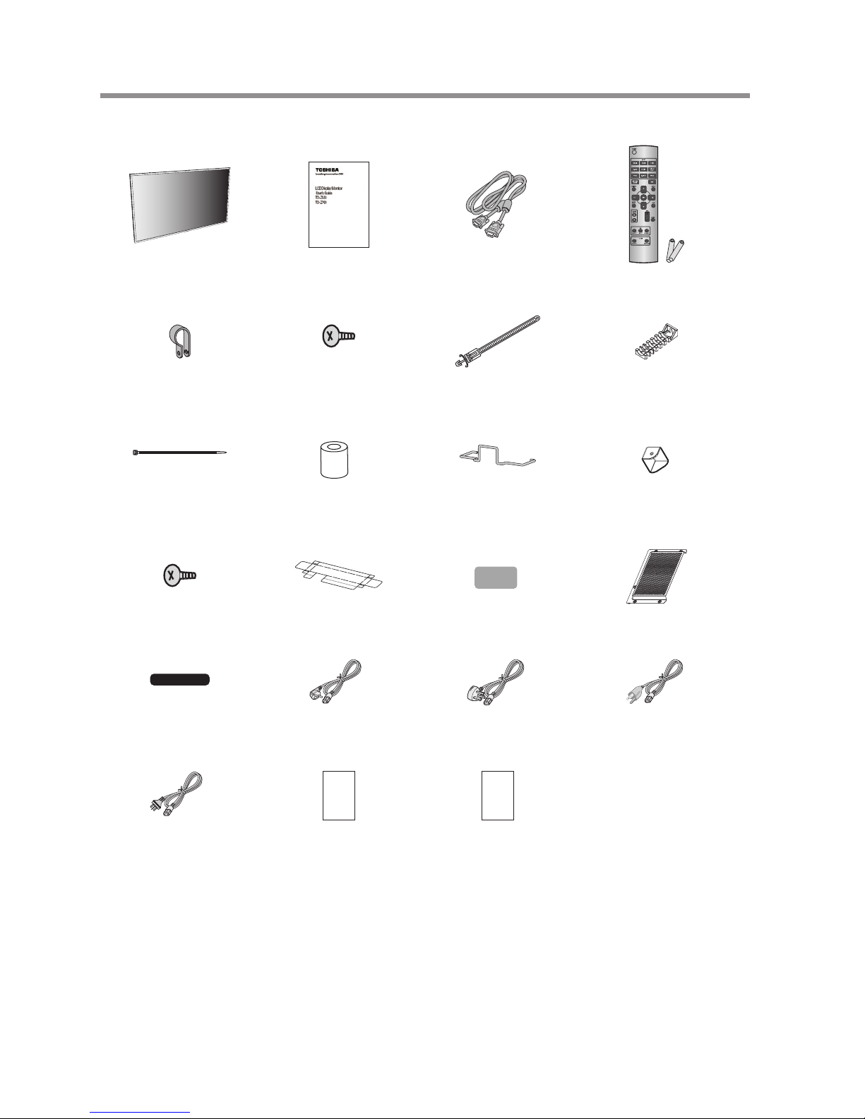
Contents
LCD Display User’s Manual Video Signal Cable
(Mini D-SUB 15-pin to Mini D-SUB 15-
pin Cable)
Wireless Remote Control and
AAA Batteries
Clamper x 2
(For fall prevention)
Screw (M4) x 2
For the monitor fall
prevention clampers)
Clamper x 3
(For tying cables)
Clamper x 2
(For holding the HDMI cables)
Band x 4
(For the HDMI cable holding
clampers)
Wall mount spacer x 9 Cable holder
(For holding the power cord)
Corner protector x 4
Screw (M3) x 4
(For the corner protectors)
Protective cover Label to cover the UL
certication marking
Option slot cover
Label to cover the logo
(Use it as necessary.)
Power Cord For EU Power Cord For UK Power Cord
For North America
Power Cord for Australia.
(Australia only)
Warranty
(US only)
Warranty
(Australia only)
The supplied power cord varies depending on destination.
For the use in the other regions, use a power cord that matches the AC voltage of the power outlet and has been approved
by and complies with the safety standard of those regions or countries.
The images contained in this document are sample illustrations and are subject to change without notice.
Contents
11
Introduction
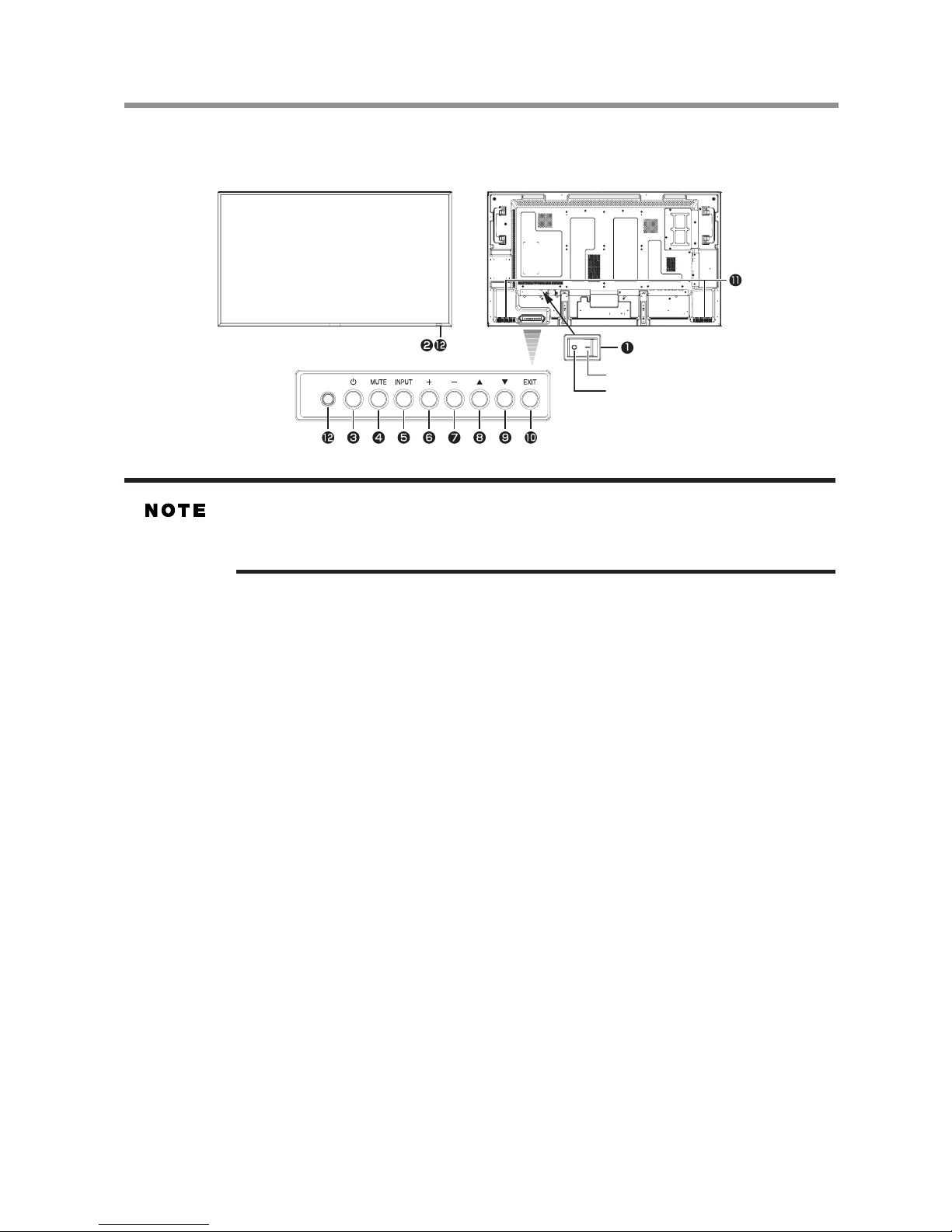
Parts Name and Functions
Buttons, Switch, and Indicator
ON
OFF
Contro l butto ns
Front Rear
1 Main Power Switch —Switches the main power on/off and is used as the disconnect device.
Within 2 seconds after turning off the power by the POWER button on the wireless remote control or the monitor or by
a communication command, don’t turn off the main power switch, don’t disconnect the power cord, and don’t turn off
the breaker. If the AC power is turned off immediately after the power-off operation, all the OSD settings including the
language selection may be reset to the factory defaults at the next power-on. If the OSD settings are reset to the factory
defaults as described above, reconfigure the OSD settings using the following procedure.
• Turn off the power of the monitor using the wireless remote control or otherwise.
• Wait for at least 2 seconds.
• Turn on the power of the monitor using the wireless remote control or otherwise.
• Check and recongure the OSD settings.
2 Remote control sensor and Power indicator—
Remote control sensor: Receives the signal from the wireless remote control.
Power indicator: Indicates the state of the LCD display.
• Steady green: The power is on.
• Steady red: The power is off. Some operations such as power-on are possible.
• Steady green and red: The LCD display is in the sleep mode.
• Off: The main power is off.
• Steady red and blinking green: The LCD display is in the schedule standby mode.
• Blinking red: The LCD display has an error (detected by the self-diagnostic function).
3 POWER button—Switches the power on/off.
This button doesn’t work when the power indicator is off. Turn on the main power. (See page 35.)
4 MUTE button—Switches the audio mute on/off.
5 INPUT button—Displays the OSD menu to switch the video input. You can select [HDMI1], [HDMI2], [DVI-D],
[D-SUB], [OPTION]*, [DISPLAYPORT], [YPbPr], [S-VIDEO], or [VIDEO] using the UP (▲) or DOWN (▼)
button.
OPTION can be used when an expansion module is mounted on the option slot.
6 PLUS (+) button—Acts as (+) button to increase the adjustment in the OSD menu. Increases the audio output level
when the OSD menu is off.
7 MINUS (-) button—Acts as (-) button to decrease the adjustment in the OSD menu. Decreases the audio output level
when the OSD menu is off.
8 UP (▲) button—Acts as (▲)button to move the highlighted area up to select an adjustment item in the OSD menu.
9 DOWN (▼) button—Acts as (▼)button to move the highlighted area down to select an adjustment item in the OSD
menu.
10 EXIT button—Activates the OSD menu when the OSD menu is off. Acts as EXIT button to go back to the previous
OSD menu.
11 Speakers—Audio sound is output from the built-in speakers.
12 Brightness sensor (on the front and rear)—Sensor for the auto brightness function.
(Reference) Control Lock mode
You can lock the operation buttons. See page 64.
For details about the OSD menu operation using the buttons, see “Basic operation of OSD.” (See page 48.)
Front Rear
Parts Name and Functions
12
Introduction
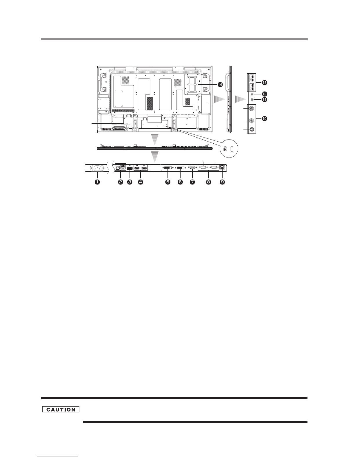
Connectors and Terminals
IN
IN
OUT
IN OUT
Main Power Switch
Rear Left side
1 AC IN (3-pin, with earth terminal)—Connects with the supplied power cord.
Class I Product requires an earthed mains supply connection.
2 USB hub—
USB upstream port (Standard B): 1
To be connected to an external computer.
USB downstream port (Standard A): 2
To be connected to peripheral devices such as digital camera and touch-panel.
3 DISPLAYPORT IN—Connects with the digital video output of a computer, etc.
4 HDMI1 IN, HDMI2 IN—Connects with the digital video output of a computer, DVD player, etc.
5 DVI-D IN—Connects with the digital video output of a computer, etc.
6 DVI-D OUT—Outputs the signal that is supplied to the DVI-D IN connector (5).
7 D-SUB/YPbPr IN—Connects with the analog video output of a computer or the component video output of a DVD
player, etc.
8 RS-232C connector (D-SUB 9-pin)—
IN connector:
Connects with the RS-232C OUT connector of a computer or other connected TD-Z551/TD-Z701.
OUT connector:
Connects with the RS-232C IN connector of other connected TD-Z551/TD-Z701.
9 LAN connector—Connects with a LAN cord.
10 VIDEO IN/OUT (S connector/BNC)—Connects with video equipment.
S-VIDEO IN: S-video input connector (MINI DIN 4-pin)
VIDEO IN: BNC connector
VIDEO OUT: BNC connector
11 AUDIO ANALOG IN—Connects with the audio output connector of external equipment such as a computer, VCR,
and DVD player.
12 AUDIO ANALOG OUT—Outputs the signal that is supplied to the AUDIO ANALOG IN connector (11). Connects
with an external audio amplier, etc.
Headphones and earphones aren’t supported.
13 EXTERNAL SPEAKER TERMINAL—Connects with the special stereo speakers.
14 Option slot—Insert an expansion module (option or commercially available) in this slot.
Damage to the product may result or monitor may not function properly if an incompatible device is installed in this
slot. See page 28.
When mounting an OPS-compliant computer (commercially available), turn on the cooling fan.
Anti-theft lock slot
You can insert an
anti-theft lock key.
Connectors and Terminals
13
Introduction
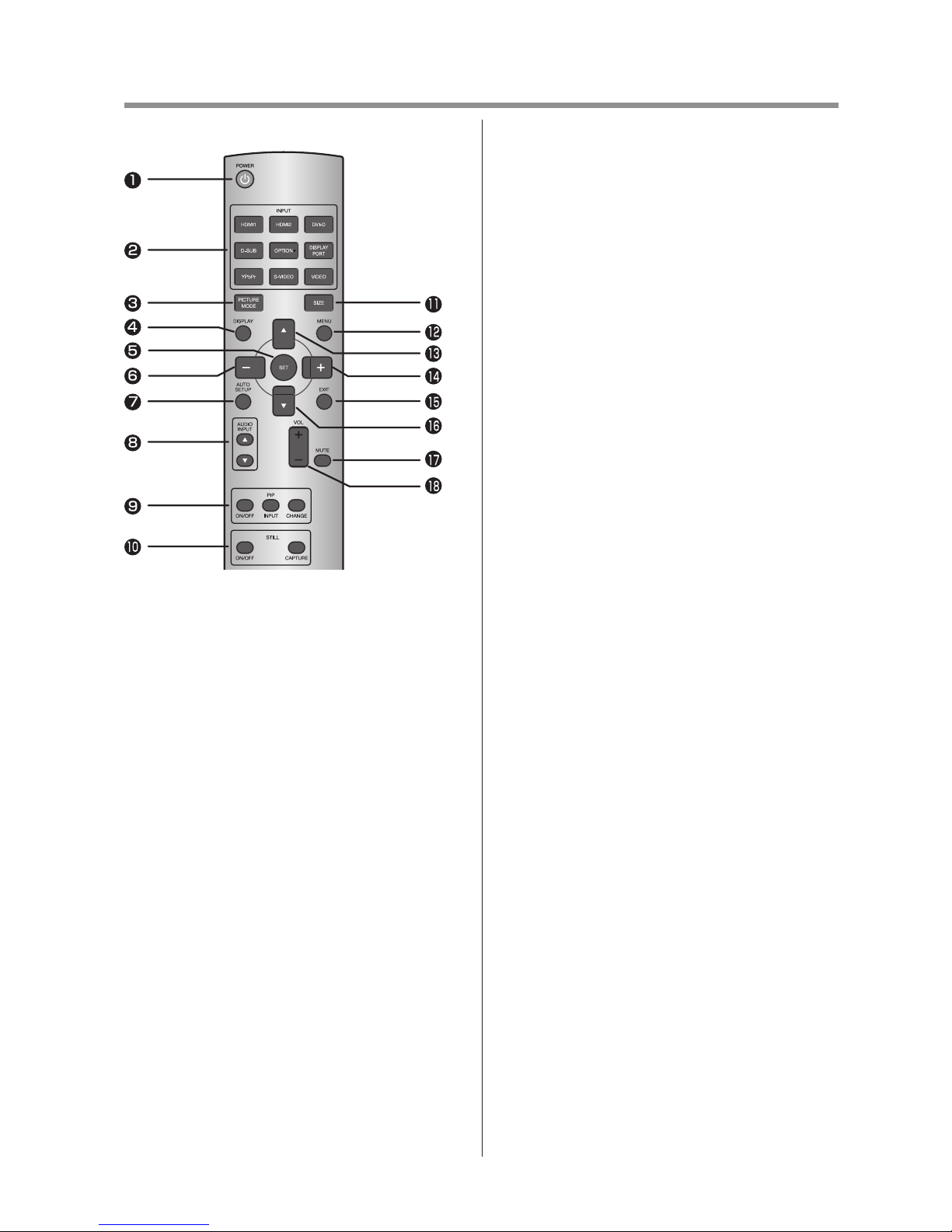
Wireless Remote Control
1 POWER button—Switches the power on/off.
When the Power indicator is not glowing, no controls
will work.
2 INPUT buttons—Select the input signal from
[HDMI1], [HDMI2], [DVI-D], [D-SUB],
[OPTION]*, [DISPLAYPORT], [YPbPr],
[S-VIDEO], and [VIDEO].
OPTION can be used when an expansion module is
mounted on the option slot.
3 PICTURE MODE button—Selects the picture
mode from [HIGHBRIGHT], [STANDARD],
[sRGB], and [CINEMA]. See page 39.
HIGHBRIGHT: The brightness is maximized.
STANDARD: Factory default setting.
sRGB: Suitable for color matching with
sRGBcompliant devices.
CINEMA: Suitable for viewing movies.
4 DISPLAY button—Displays the screen information.
See page 64. When the remote control mode is LOCK,
you can set it back to NORMAL by holding down the
DISPLAY button for at least 5 seconds (see page 61).
5 SET button—Accepts the settings made in the OSD
menu.
6 MINUS button (-)—Acts as (-) button to decrease the
adjustment in the OSD menu.
When the PIP mode is active, this button moves the
sub picture to the left.
7 AUTO SETUP button—Displays the auto setup
menu. See pages 38 and 56.
8 AUDIO INPUT buttons—Selects the audio input
according to the video input.
This button works only while any of HDMI1,
HDMI2, OPTION (OPS-compliant computer), or
DISPLAYPORT video input is selected. See page 65.
9 PIP (Picture-In-Picture) buttons—
ON/OFF button: Switches the PIP or POP mode on/
off.
INPUT button: Selects video to be displayed in the
sub picture.
CHANGE button: Changes the main picture with the
sub picture.
[Description]
PIP: Picture-In-Picture
The sub picture is displayed within the main picture.
POP: Picture-Outside-Picture
The sub picture is displayed to the bottom right of the
main picture.
SBS: Side-By-Side
The main picture and the sub picture are displayed
side by side.
When the screen size is [CUSTOM] or [REAL], the
PIP and POP modes don’t work.
10 STILL button—
ON/OFF button: Switches the still picture mode on/
off.
CAPTURE button: Captures the new picture.
11 SIZE button—Selects the picture size from [FULL],
[NORMAL], [CUSTOM], [DYNAMIC], and
[REAL]. See page 63.
12 MENU button—Switches the OSD menu mode on/
off.
13 UP button (▲)—Acts as (▲) button to move the
highlighted area up to select an adjustment item in the
OSD menu. When the PIP mode is active, this button
moves the sub picture up.
14 PLUS button (+)—Acts as (+) button to increase the
adjustment in the OSD menu. When the PIP mode is
active, this button moves the sub picture to the right.
15 EXIT button—Displays the previous OSD menu.
16 DOWN button (▼)—Acts as (▲) button to move the
highlighted area down to select an adjustment item in
the OSD menu. When the PIP mode is active, this
button moves the sub picture down.
17 MUTE button—Switches the mute function on/off.
18 VOLUME buttons (VOL)—Pressing the plus (+)
side increases the audio output level. Pressing the
minus (-) side decreases the audio output level.
Wireless Remote Control
14
Introduction
How to Use the Wireless Remote Control
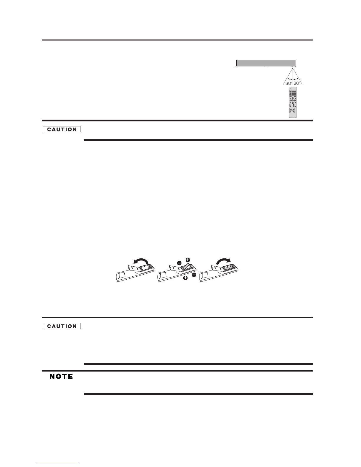
Operating Range of the Wireless Remote Control
Point the wireless remote control toward the LCD display’s remote control sensor
during button operation.
Use the wireless remote control within a distance of about 7 m from the front of the
LCD display’s remote control sensor and at a horizontal and vertical angle of within
30° within a distance of about 3.5 m.
The remote control system may not function when direct sunlight or strong illumination strikes the remote control
sensor of the LCD display, or when there is an object in the path.
Handling the wireless remote control
* Do not subject to strong shock.
* Do not allow water or other liquid to splash on the wireless remote control. If the wireless remote control gets wet, wipe it dry
immediately.
* Avoid exposure to heat and steam.
* Other than to install the batteries, do not open the wireless remote control.
Installing and removing the wireless remote control batteries
The wireless remote control is powered by 1.5 V AAA batteries.
How to install the batteries
1 Unlock and pull up the cover in the arrow’s direction.
2 Align the batteries according to the (+) and (-) indications inside the case.
3 Replace the cover.
How to remove the batteries
1 Unlock and pull up the cover in the arrow’s direction.
2 Remove the batteries.
Incorrect use of batteries can result in leaks or explosion.
Be careful especially about the following points.
• Place “AAA” batteries matching the (+) and (-) signs on each battery to the (+) and (-) signs of battery compartment.
• Do not mix battery types.
• Do not combine new batteries with used ones. It causes shorter battery life or leakage of batteries.
• Remove dead batteries immediately to prevent battery liquid from leaking into the battery compartment.
Don’t touch exposed battery acid because it causes damage to your skin.
• When the wireless remote control doesn’t work at all or it works only within a short distance to the monitor, change
both batteries with new ones.
• If you do not use the wireless remote control for a long period, remove the batteries.
How to Use the Wireless Remote Control
15
Chapter 2
Preparation for use
Preparation for installation
Determine the installation location
DO NOT ATTEMPT TO INSTALL THE LCD DISPLAY BY YOURSELF.
Installing your LCD display must be done by a qualied technician. Contact your dealer for more information.
MOVING OR INSTALLING THE LCD DISPLAY MUST BE DONE BY TWO OR MORE PEOPLE.
Failure to follow this warning may result in injury if the LCD display falls.
Proper operation of the monitor is not guaranteed when it is mounted upside down or face down.
Lay the protective sheet, which was wrapped around the LCD display when it was packaged, beneath the LCD display
so as not to scratch the panel.
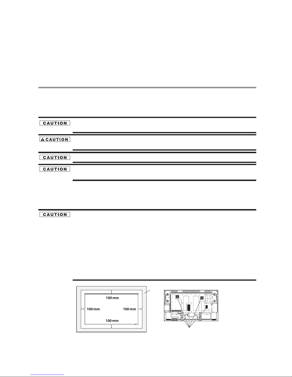
Ventilation requirements for enclosure mounting
To allow heat to disperse, leave space around the monitor as shown in the gure below.
Don’t block the holes in the rear of the monitor shown in the figure above. If they are blocked, heat accumulates inside
the monitor, causing breakdown. The upper limit of the operationguaranteed ambient temperature when the monitor is
installed in the landscape position is 40°C. When installing the monitor in a case or an enclosure, ensure adequate
ventilation to keep the temperature inside the case 40°C or lower by providing a cooling fan or ventilation holes in the
case. The upper limit when the monitor is in the portrait or face-up position is 35°C.
This LCD has a temperature sensor and cooling fan. If the LCD becomes hot, the cooling fan will turn on automatically.
If the LCD becomes overheated, the “Caution” menu will appear. If the “Caution” menu appears, stop using the
monitor and allow it to cool. When the LCD display is used in an enclosure or with protection on LCD surface, please
check the inside temperature of the monitor by “HEAT STATUS” (See page 62). If the temperature is higher than the
normal level, set “COOLING FAN” to ON using the SCREEN SAVER function (See page 56). When mounting an
OPS-compliant computer (commercially available), turn on the cooling fan.
Don’t block these holes.
Wall
16
Preparation for use
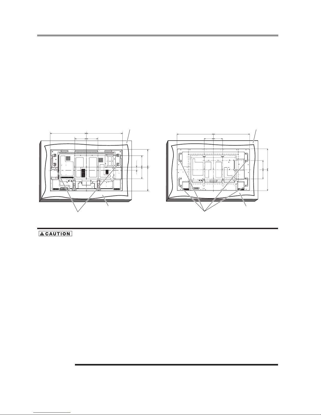
Using the wall mount or ceiling mount
Lay the screen face down
Lay the protective sheet on a table, which was wrapped around the monitor when it was packaged, beneath the screen
surface so as not to scratch the screen surface.
This device cannot be used or installed without the Tabletop Stand or other mounting accessory. Failure to follow the
correct mounting procedures can result in damage to the equipment or injury to the user or installer. Product warranty does
not cover damage caused by improper installation. Failure to follow these recommendations can void your warranty.
For installation, use M6 screws (with a loose-proof spring washer and having a length 10 mm longer than the thickness of
the mounting bracket) and tighten them securely.
Toshiba recommends using a mounting interface that complies with VESA Requirements, TUV-GS or for North America
UL1678.
55” 70”
200 200
624 624
200200
307.5411.5
52
Handles
Protective Sheet
(mm)
Table
792.5 792.5
200 200
002 002
457.5457.5
Handles
Protective Sheet
(mm)
Table
For preventing the monitor from falling:
• Install the monitor with metal brackets for wall or ceiling installation (commercially available) on your own
responsibility. For detailed procedures of installation, refer to the instructions of the metal brackets.
• To lessen the probability of injury and damage resulting from fall of the monitor in case of earthquake or other
disaster, be sure to consult the bracket manufacturer for installation location.
• To lessen the risk of falling of the monitor, thread commercially available rope through the handles at the right and
left of the monitor and secure the rope to the wall mount brackets or ceiling mount brackets. Use rope that can bear a
load 6 times the weight of the monitor (55” approximately 171 kg; 70” approximately 275 kg ).
• Do not sleep where the monitor may topple over or fall in case of an earthquake or other disaster.
• Use screws having enough strength to support the LCD display monitor (made of stainless steel etc.).
About the metal bracket:
• Use a VESA-compliant metal bracket.
• Before installation, make sure that the installation surface has sufficient strength.
• Use a metal bracket (commercially available) that is strong enough to hold the monitor.
• Before installation, check the strength and other properties to ensure the safety.
• Do not block the heat dissipating holes in the monitor with the metal bracket. See page 15.
• For details of the mounting procedure and the safe installation procedure, see the user instructions of the metal
bracket (commercially available) to be used.
• Take measures such as using multiple metal brackets, holding the monitor at several points, and taking measures to
prevent falling or dropping in case of a problem.
Using the wall mount or ceiling mount
17
Preparation for use
Installing the monitor
Installing the monitor
Preventing the handles from touching the wall
By attaching the handles in the opposite orientation, you can reduce the depth of the monitor.
1 Remove the screws that are holding the handles.
55” 70”
Handle
Screws
Screw x 4
Handle
Screws
Screw x 8
2 Attach the handles in the opposite orientation and secure them using the screws you have removed in step 1.
55” 70”
Handle
Screws
Screw x 4
Handle
Screws
Screw x 8
Removing the stand guide frames
By removing the stand guide frames, you can reduce the depth of the monitor.
1 Remove the screws that are holding the stand guide frames.
Stand guide frame
Screws
Screw x 4
2 Slightly move and remove the stand guide frames.
Retain the stand guide frames and the screws that you have removed because they are necessary to install the monitor using the
option stands.
Installing the monitor
18
Preparation for use
Installing the monitor
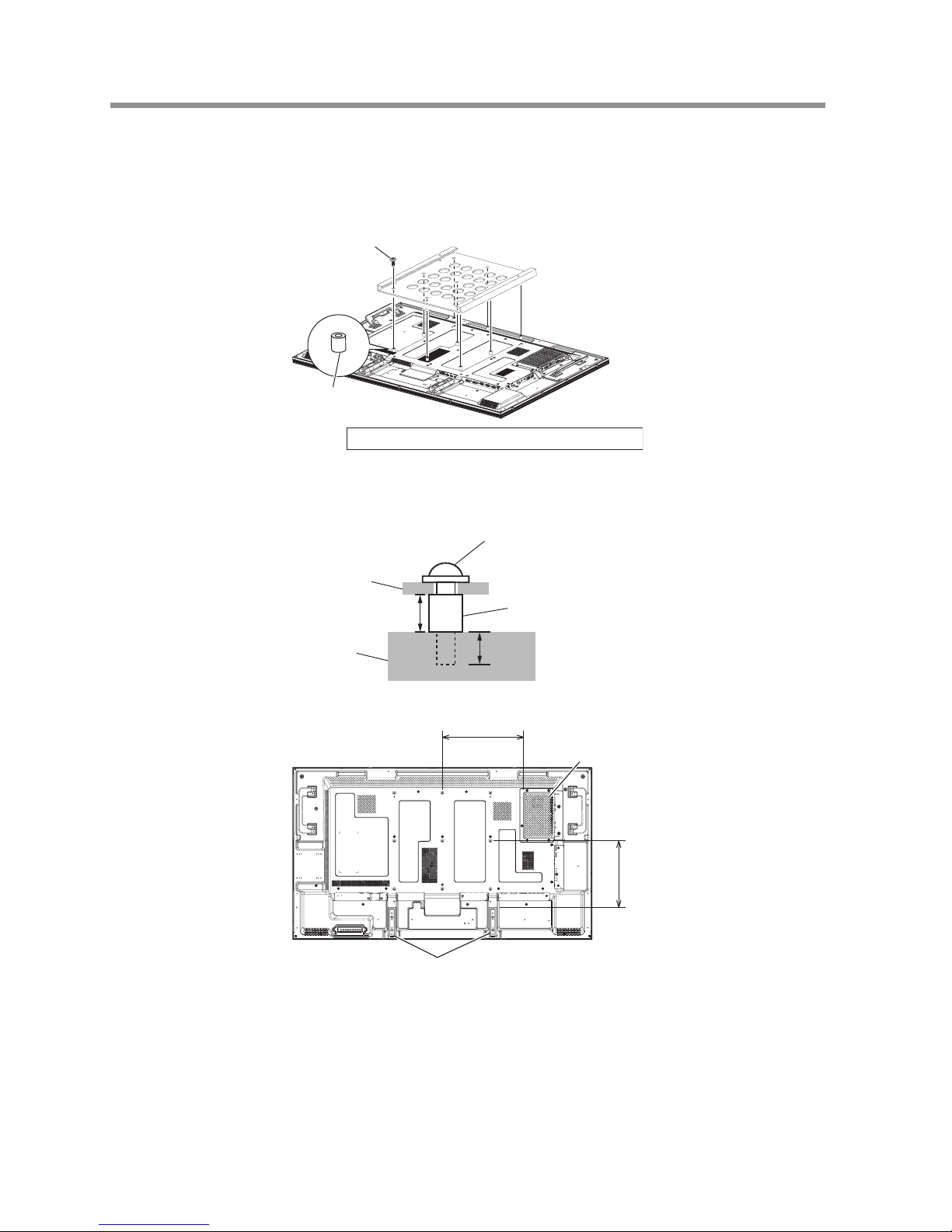
Using the wall mount spacers
When the option slot cover or the stand guide frames touch the wall or block the heat dissipating holes in the rear of the
monitor, use the wall mount spacers (accessories) to mount the metal bracket (commercially available).
1 Put the wall mount spacers (9 pcs.) between the metal bracket and the wall mount screw holes of the monitor and
attach them using screws (a).
(a)
Wall mount spacer
(accessory)
(a): Screw for attaching the wall mount spacer (M6, 9 pcs.)
For mounting, use M6 screws (with a loose-proof spring washer, long enough to accommodate the thickness of the metal
bracket and that of the wall mount spacer (17 mm) and penetrate the monitor to a depth of 10 mm) and tighten them
securely.
10 mm
17 mm
339
276
Screw
Metal bracket
Wall mount spacer
(accessory)
Monitor
Stand guide frames
Option slot cover
(accessory)
Using the wall mount spacers
19
Preparation for use
Installing the monitor
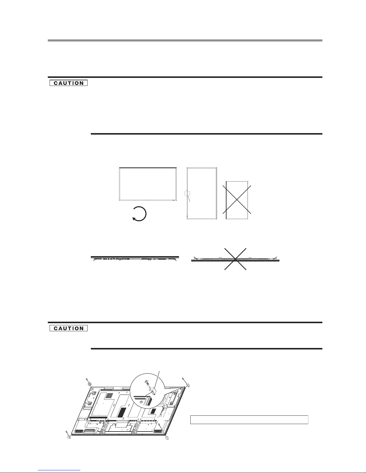
Installing in the portrait or face-up position
The monitor can be installed in the portrait or face-up position.
Ensure that the monitor is oriented as shown below.
• The operating environmental condition (temperature) when the monitor is in the portrait or face-up position is 0°C to 35°C.
• Proper operation of the monitor is not guaranteed when it is not mounted as shown below (upside down, face down, etc.).
• When mounting an OPS-compliant computer (commercially available), be sure to set COOLING FAN to ON using
SCREEN SAVER in the CONFIGURATION1 menu of the OSD screen function. If it is set to AUTO, the life of the
computer may become shorter than that with it set to ON or the computer may have trouble.
• In the portrait or face-up position, the lifetime of the backlight is shorter than that in the landscape position.
• When the monitor is in the face-up position, be sure to set COOLING FAN to ON using SCREEN SAVER in the
CONFIGURATION1 menu of the OSD screen function.
Installation in the portrait position
The logo should be on the LEFT side when viewed from the front of the monitor.
This monitor doesn’t have a function to rotate displayed images. To display images in the portrait orientation, use already rotated images.
90° Clockwise
Portrait
Portrait
logo
Land scape
Installation in the face-up position (55” Only)
Face-up Face-down
Operation environment for portrait or face-up installation
When the monitor is installed in the portrait or face-up position, the following conditions should be satised.
Temperature 0 - 35°C / 32 - 95°F Humidity 20 - 80% (without condensation)
Attaching the corner protectors
It is recommended to use the corner protectors (accessories). When installing the monitor, hold its body firmly. If you
hold the monitor by the corner protectors when moving it, the monitor may detaches and fall from the corner
protectors, causing injuries.
1 Attach the corner protectors using the accessory screws (c)
(c)
(c)
(c)
(c)
(c)
(c): Screw for attaching the corner protector (M3, 4 pcs.)
Corner protector
Installing in the portrait or face-up position
20
Preparation for use
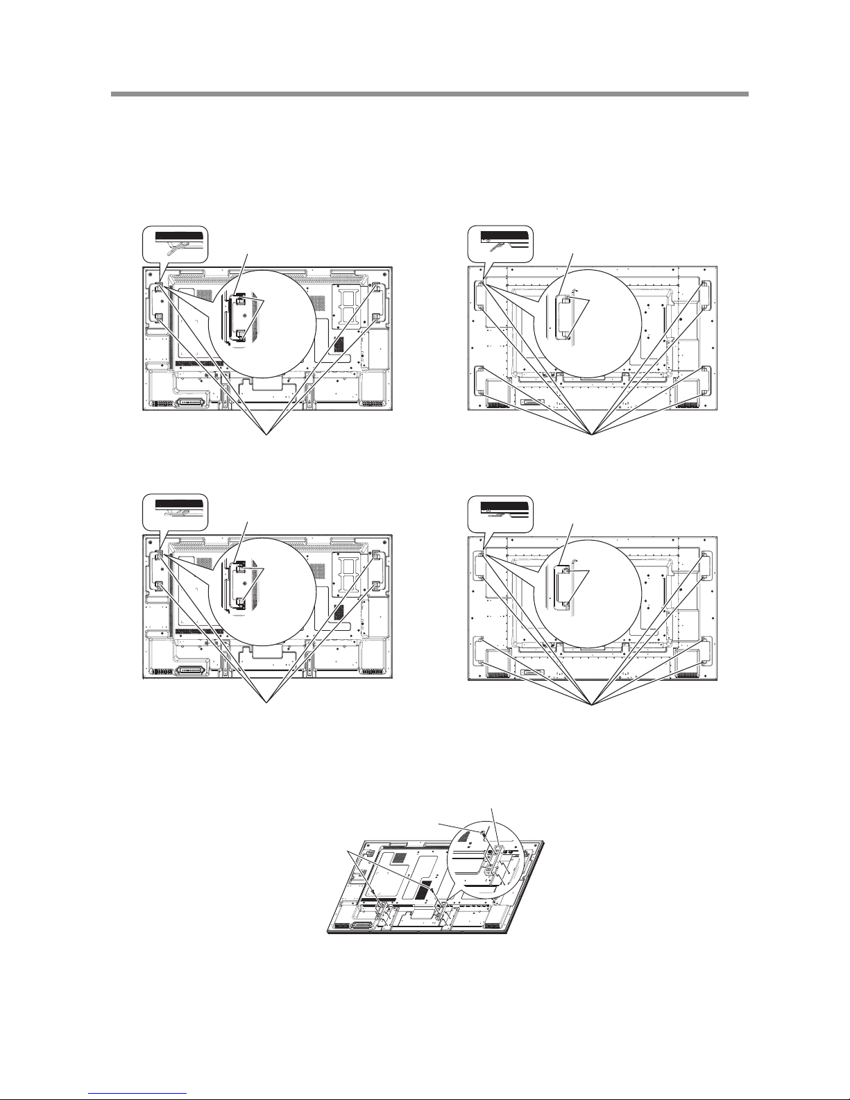
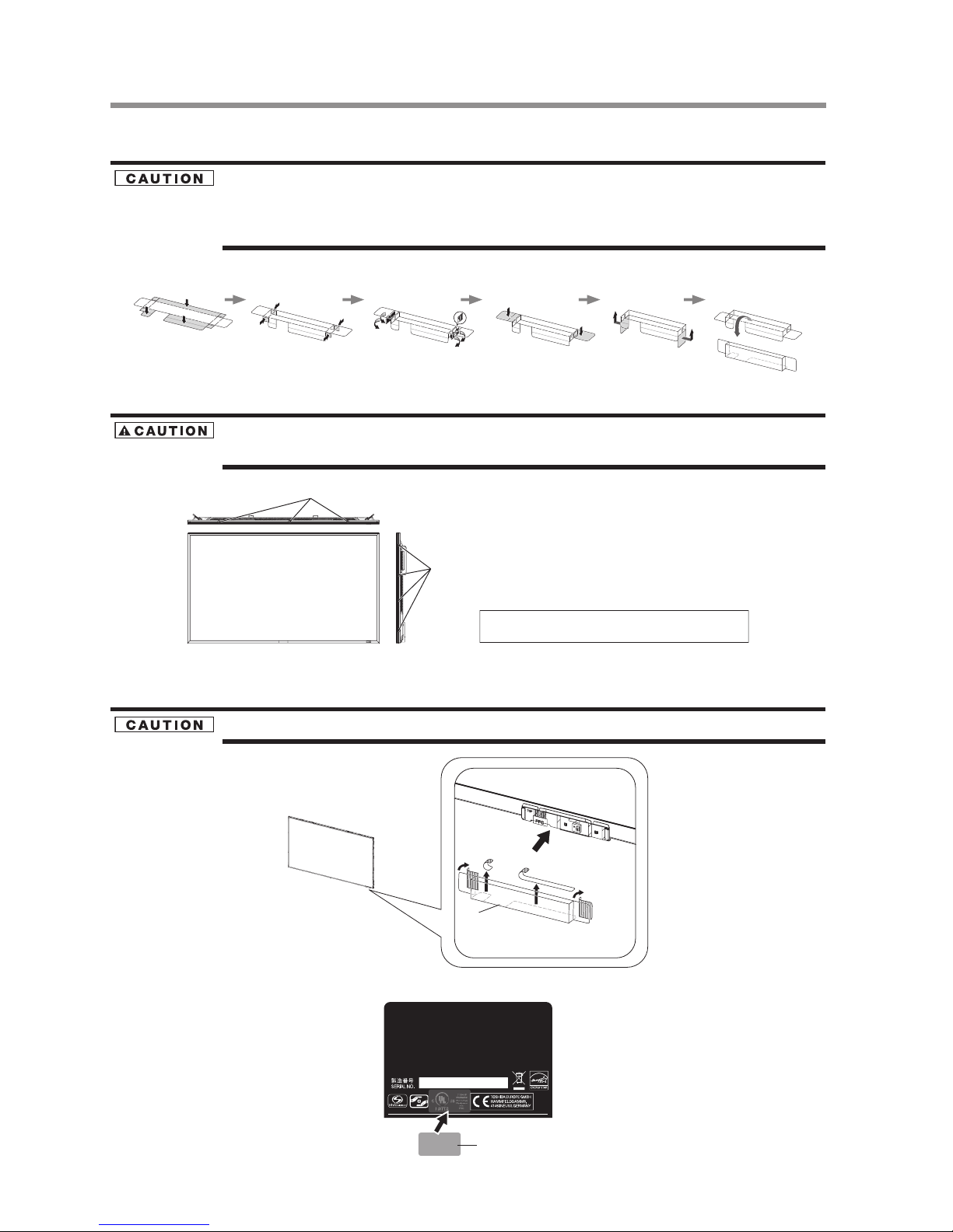
Using the monitor without the bezel
Using the monitor without the bezel
• TD-Z551 and TD-Z701 satises the UL requirements as long as it is used with the bezel attached. When using the
monitor without the bezel, in which case the monitor doesn’t satisfy the UL requirements, cover the UL certication
marking on the rear panel with the supplied label.
• To prevent static damage to circuit boards, attach the protective cover to the LCD panel.
1 Assemble the supplied protective cover according to the following procedure.
Peel off the separators.
2 Unscrew the screws (a) that hold the bezel to remove the bezel from the monitor.
If you remove other screws than the screws (a), the bezel falls apart. If you do so, the bezel may fall, causing injury or
damaging the monitor.
(a)
(a)
(a): Screws for securing the bezel (M3, 14 pcs.) for 55”
(M3, 18 pcs.) for 70”
3 Peel off the separators from the protective cover (b) assembled in step 1 and then attach the protective cover to the
LCD panel.
Never touch the circuit boards because they may be damaged.
(b)
Peel off the sepa rators.
4 Cover the UL certication marking on the rear panel with the supplied label (c).
(c)
Using the monitor without the bezel
21
Preparation for use
Installing the monitor
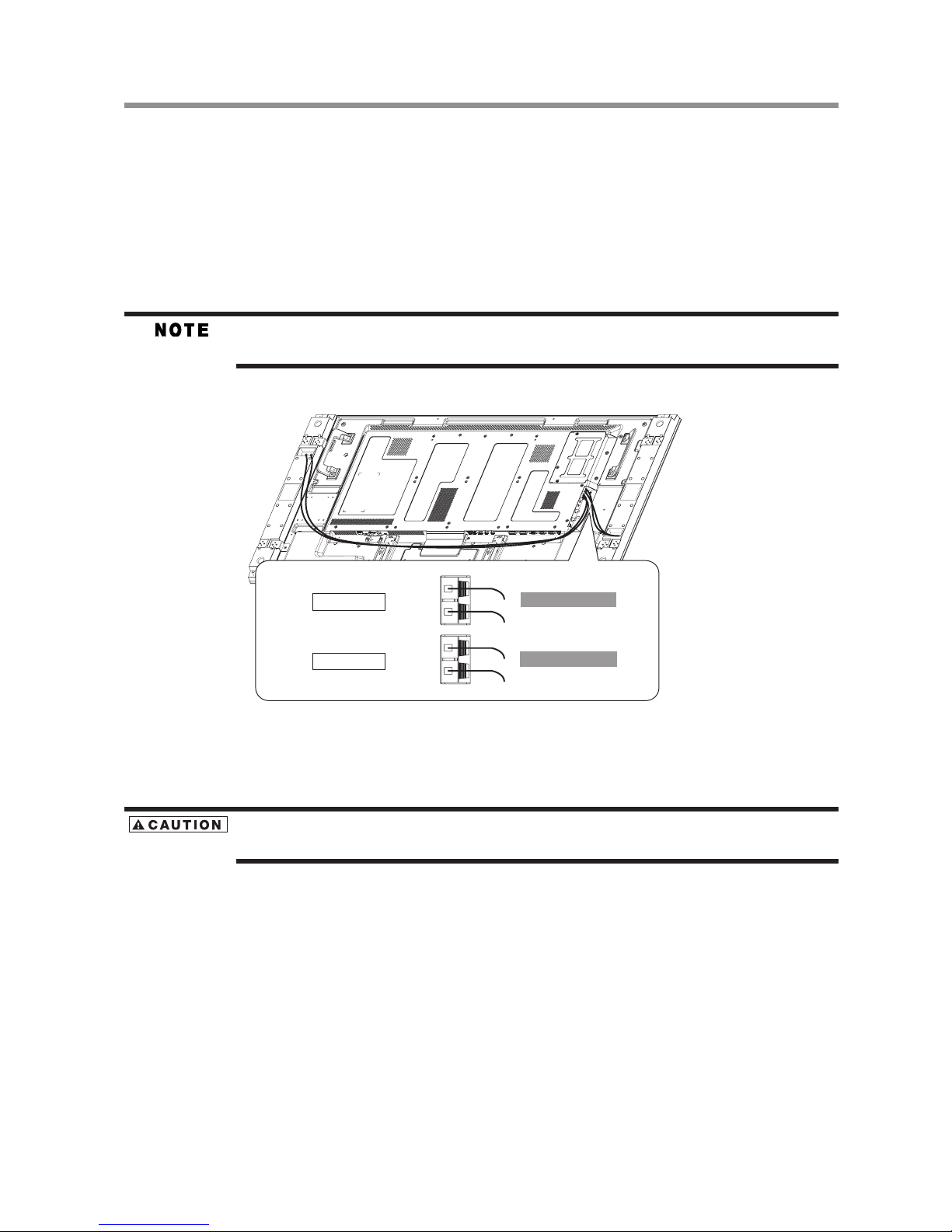
Installing the external speakers
How to install the external speakers
1 Install the external speakers on the monitor. Recommend spec- impedance 8 ohm, audio output 10W+10W (stereo)
( See page 71.)
Use the metal ttings and screws supplied with the external speakers.
Please refer to Quick Setup Guide of the external speakers for the detailed installation procedure.
2 Insert the left speaker cable into the SPEAKER (S)(L) on the monitor, and insert the right speaker cable into the SPEAKER
(S)(R).
Match the polarity of the speaker cables and that of the terminals (+ (red)/- (black)).
Unmatched polarity may cause problems with audio output.
Left speaker
(Only for reference)
Right speaker
(Only for reference)
To speaker terminal (L)
To speaker terminal (R)
SPEAK ER (S)(L)
SPEAK ER (S)(R)
Black(-)
Red(+)
Black(-)
Red(+)
(Sample Illustration) 55”
Switch the built-in speaker mode to external speaker mode after you power on the monitor. See the page for “Speaker
setting” for further details. (See page 40.)
Don’t hold the speakers when moving the monitor.
The monitor and the speakers may be damaged and you may be injured if the monitor falls.
Installing the external speakers
22
Preparation for use
Connection procedure
Connection procedure
Before making connections:
• First turn off the power of all the connected equipment before making connections.
• Refer to the user manual of each piece of equipment.
Please use the audio cable without resistance when the audio output terminal of the audio device and PC is stereo
mini-Jack. When the audio cable with resistance is used, the audio level may be affected or no sound could be heard.
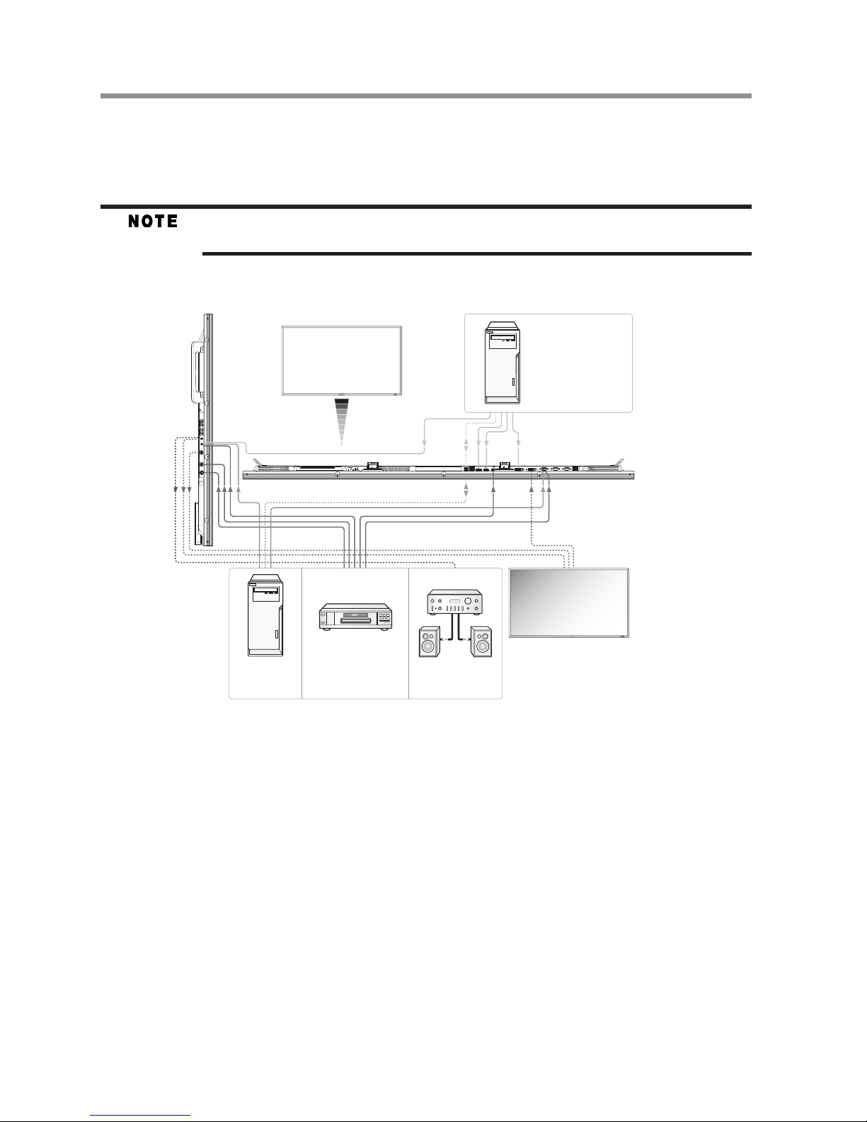
Wiring diagram
Personal c omputer
(DVI-D, HDMI , DISPLAYPORT )
Personal c omputer
(Analog RG B)
LCD display (second display)
DVD player or HD di sk
player (HDMI , BNC)
Stereo amp lifi er
Extern al speakers
LCD display
(fi rst di splay)
LCD display(front)
(Sample Illustration) 55”
Connection procedure

23
Preparation for use
Connection procedure
Prevention of disconnection of HDMI cable
For connecting an HDMI cable to the connector on the monitor, it is recommended to secure the cable using an accessory
clamper to prevent accidental disconnection.
1 Connect an HDMI cable to the connector on the monitor.
2 Secure the HDMI cable using a clamper (accessory) and a band (accessory).
1) Remove the screw from the monitor.
2) Attach the clamper to the monitor using the screw you have removed in step .
3) Secure the HDMI cable and the clamper using the band.
The band isn’t reusable. The monitor comes with 2 spare bands.
To replace the band, cut and remove the existing band and attach a new one of the same shape (commercially available,
2.5 mm in width and approximately 100 mm in length).
Screw
HDMI cable
Clamper (accessory)
Band (accessory)
3. Secure the HDMI cable using a clamper (accessory) and a band (accessory).
Clamper (accessory)
Prevention of disconnection of HDMI cable
 Loading...