

Page 1
TDP-WX5400
DATA PROJECTOR
OWNER’S MANUAL
Before UsingPreparationsOperationsMaintenanceOthers
Page 2
2
3
Before Using
Before Using
SAFETY PRECAUTIONS
The lightning ash with arrowhead symbol, within an equilateral triangle, is intended to
alert the user to the presence of uninsulated "dangerous voltage" within the product's
enclosure that may be of sufcient magnitude to constitute a risk of electric shock to
persons.
The exclamation point within an equilateral triangle is intended to alert the user to
the presence of important operating and maintenance (servicing) instructions in the
literature accompanying the appliance.
WARNING: TO REDUCE THE RISK OF FIRE OR ELECTRIC SHOCK, DO NOT EXPOSE THIS
APPLIANCE TO RAIN OR MOISTURE. DANGEROUS HIGH VOLTAGES ARE PRESENT
INSIDE THE ENCLOSURE. DO NOT OPEN THE CABINET. REFER SERVICING TO
QUALIFIED PERSONNEL ONLY.
WARNING:
USA only
Handling the cord on this product or cords associated with accessories sold with this
product, will expose you to lead, a chemical known to the State of California to cause
birth defects or other reproductive harm.
Wash hands after handling
.
-
Reorient or relocate the receiving antenna.
-
Increase the separation between the equipment and receiver.
-
Connect the equipment into an outlet on a circuit different from that to which the receiver
is connected.
-
Consult the dealer or an experienced radio/TV technician for help.
RESPONSIBLE PARTY:
WARNING:
USA only
Notice:
CANADA only
TOSHIBA AMERICA INFORMATION SYSTEMS, INC.
9740 Irvine Blvd., Irvine, CA 92618-1697 U.S.A
Phone: (949) 583-3000
Changes or modications made to this equipment, not expressly approved by
Toshiba, or parties authorized by Toshiba, could void the user’s authority to operate
the equipment.
This Class B digital apparatus complies with Canadian ICES-003. Cet appareil
numérique de la classe B est conforme à la norme NMB-003 du Canada.
WARNING:
USA only
MODEL NAME: TDP-WX5400
TRADE NAME: DATA PROJECTOR MODEL NAME: TDP-WX5400
FOR HOME OR OFFICE USE
FCC NOTICE: This device complies with part 15 of the FCC Rules. Operation is subject to the
following two conditions:
(1) This device may not cause harmful interference, and (2) this device must accept any
interference received, including interference that may cause undesired operation.
This equipment has been tested and found to comply with the limits for a Class B digital device,
pursuant to part 15 of the FCC Rules. These limits are designed to provide reasonable protection
against harmful interference in a residential installation. This equipment generates, uses and can
radiate radio frequency energy and, if not installed and used in accordance with the instructions,
may cause harmful interference to radio communications.
However, there is no guarantee that interference will not occur in a particular installation.
If this equipment does cause harmful interference to radio or television reception, which can be
determined by turning the equipment off and on, the user is encouraged to try to correct the
interference by one or more of the following measures:
Lamp contains mercury. Disposal of this product may be regulated due to
environmental considerations. For disposal, reuse or recycling information, please
contact your local government or the Electronic Industries Alliance at www.eiae.org.
USA only
Tested To Comply
With FCC Standards
Page 3
4
5
Before Using
IMPORTANT SAFETY INSTRUCTIONS
CAUTION: PLEASE READ AND OBSERVE ALL WARNINGS AND INSTRUCTIONS GIVEN IN
THIS OWNER'S MANUAL AND THOSE MARKED ON THE UNIT. RETAIN THIS
BOOKLET FOR FUTURE REFERENCE.
This unit is fully transistorized and does not contain any parts that can be repaired by the user.
DO NOT REMOVE THE CABINET COVER, OR YOU MAY BE EXPOSED TO DANGEROUS
VOLTAGE. REFER SERVICING TO QUALIFIED SERVICE PERSONNEL ONLY.
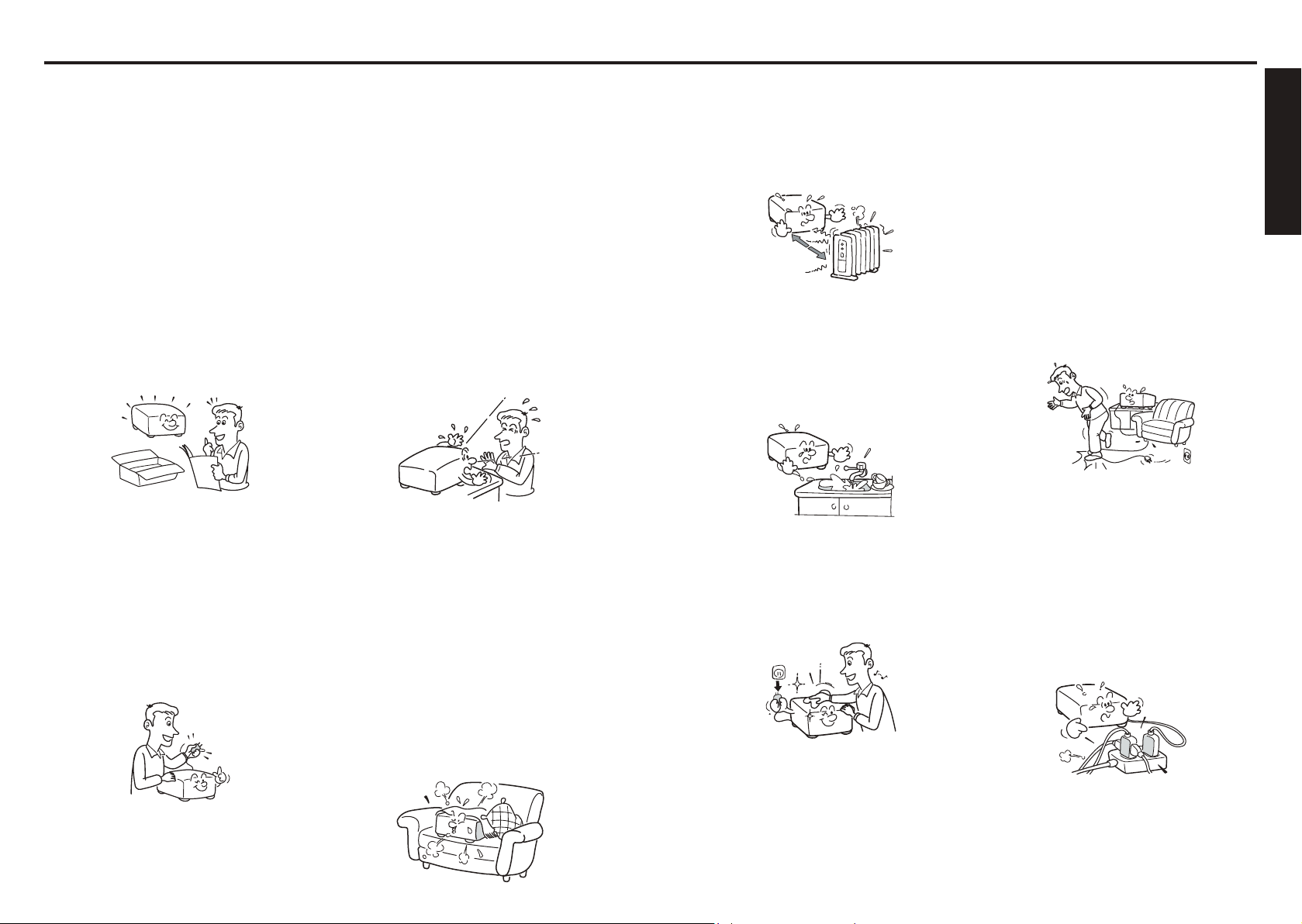
1. Read Owner’s Manual
After unpacking this product, read
the owner's manual carefully, and
follow all the operating and other
instructions.
2. Power Sources
This product should be operated
only from the type of power source
which does not exceed the voltage
range specied on the
the power cord.
If you are not sure of the type of
power supply to your home, consult
your product dealer or local power
company.
rating label and
3. Source of Light
Do not look into the lens while the
lamp is on. The strong light from
the lamp may cause damage to your
eyesight.
4. Ventilation
Openings in the cabinet are provided
for ventilation and to ensure reliable
operation of the product and to
protect it from overheating, and
these openings must not be blocked
or covered.
The openings should never be
blocked by placing the product
on a bed, sofa, rug or other similar
surface. This product should not be
placed in a built-in installation such
as a bookcase or rack unless proper
ventilation is provided.
5. Heat
The product should be situated away
from heat sources such as radiators,
heat registers, stoves, or other
products (including ampliers) that
produce heat.
6. Water and Moisture
Do not use this product near water.
- for example, near a bath tub, wash
bowl, kitchen sink, or laundry tub; in
a wet basement; or near a swimming
pool and the like.
7. Cleaning
Unplug this product from the wall
outlet before cleaning. Do not use
liquid cleaners or aerosol cleaners.
Use a soft cloth for cleaning.
8. Be sure that you firmly insert
the plug into the wall outlet.
Incorrect or faulty connections may
result in re or electric shock. Avoid
using an unsound or loose outlet.
9. Power-Cord Protection
Power-supply cords should be
routed so that they are not likely to
be walked on or pinched by items
placed upon or against them, paying
particular attention to cords at
plugs, convenience receptacles, and
the point where they exit from the
product.
10. Overloading
Do not overload wall outlets; to
reduce the risk of electric shock, do
not use the polarized plug with an
extension cord , receptacle, or other
outlet unless the blades can be
inserted completely with three-wire
grounding type to prevent blade
exposure. As this can result in a risk
of re or electric shock.
Page 4
6
7
Before Using
IMPORTANT SAFETY INSTRUCTIONS (Continued)
S3125A
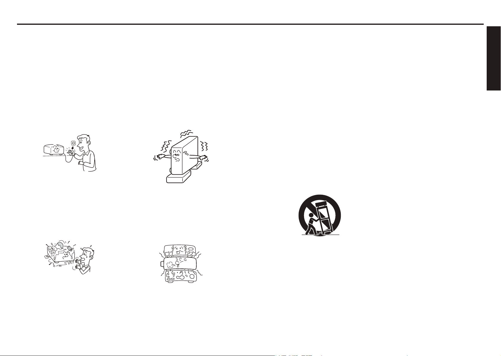
11. Lightning storms
For added protection for this product
during storm, or when it is left
unattended and unused for long
periods of time, unplug it from the
wall outlet. This will prevent damage
to the product due to lightning and
power-line surges.
However, while it is thundering
or lightning, do not touch the
apparatus and any connected cable
and/or equipment.
This will prevent you from receiving
the electric shock by an electric
surge.
12. Object and Liquid Entry
Never push objects of any kind into
this product through openings as
they may touch dangerous voltage
points or short-out parts that could
result in a re or electric shock.
Never spill liquid of any kind on the
product.
13. Do not place or keep the
projector within the reach of
the children.
It may fall down or tip over, which
could result in severe injury.
14. Do not place the product
vertically
Do not use the product in the
upright position to project the
pictures at the ceiling, or any other
vertical positions. It may fall down
and dangerous.
15. Stack Inhibited
Do not stack other equipment on this
product or do not place this product
on the other equipment. Top and
bottom plates of this product
develops heat and may give some
undesirable damage to other unit.
16. Moving the projector
When carrying the projector, be sure
to use the carrying handle to avoid
any damage to the lens or main unit.
17. Attachments
Do not use attachments not
recommended by product
manufacturer as they may cause
hazards.
18. Accessories
Do not place this product on an
unstable cart, stand, tripod, bracket,
or table. The product may fall,
causing serious injury to a child
or adult, and serious damage to
the product. A product and cart
combination should be moved with
care. Quick stops, excessive force,
and uneven surfaces may cause the
product and cart combination to
overturn.
19. Damage Requiring Service
Unplug this product from the
wall outlet and refer servicing to
qualified service personnel under the
following conditions:
a) When the power-supply cord or plug
is damaged.
b) If liquid has been spilled, or objects
have fallen into the product.
c) If the product has been exposed to
rain or water.
d) If the product does not operate
normally by following the operating
instructions. Adjust only those
controls that are covered by
the operating instructions as an
improper adjustment of other
controls may result in damage and
will often require extensive work by
a qualied technician to restore the
product to its normal operation.
e) If the product has been dropped or
damaged in any way (If the cabinet
should break, please handle with
care to avoid injury) .
f) When the product exhibits a distinct
change in performance - this
indicates a need for service.
Page 5
8
9
Before Using
IMPORTANT SAFETY INSTRUCTIONS (Continued)
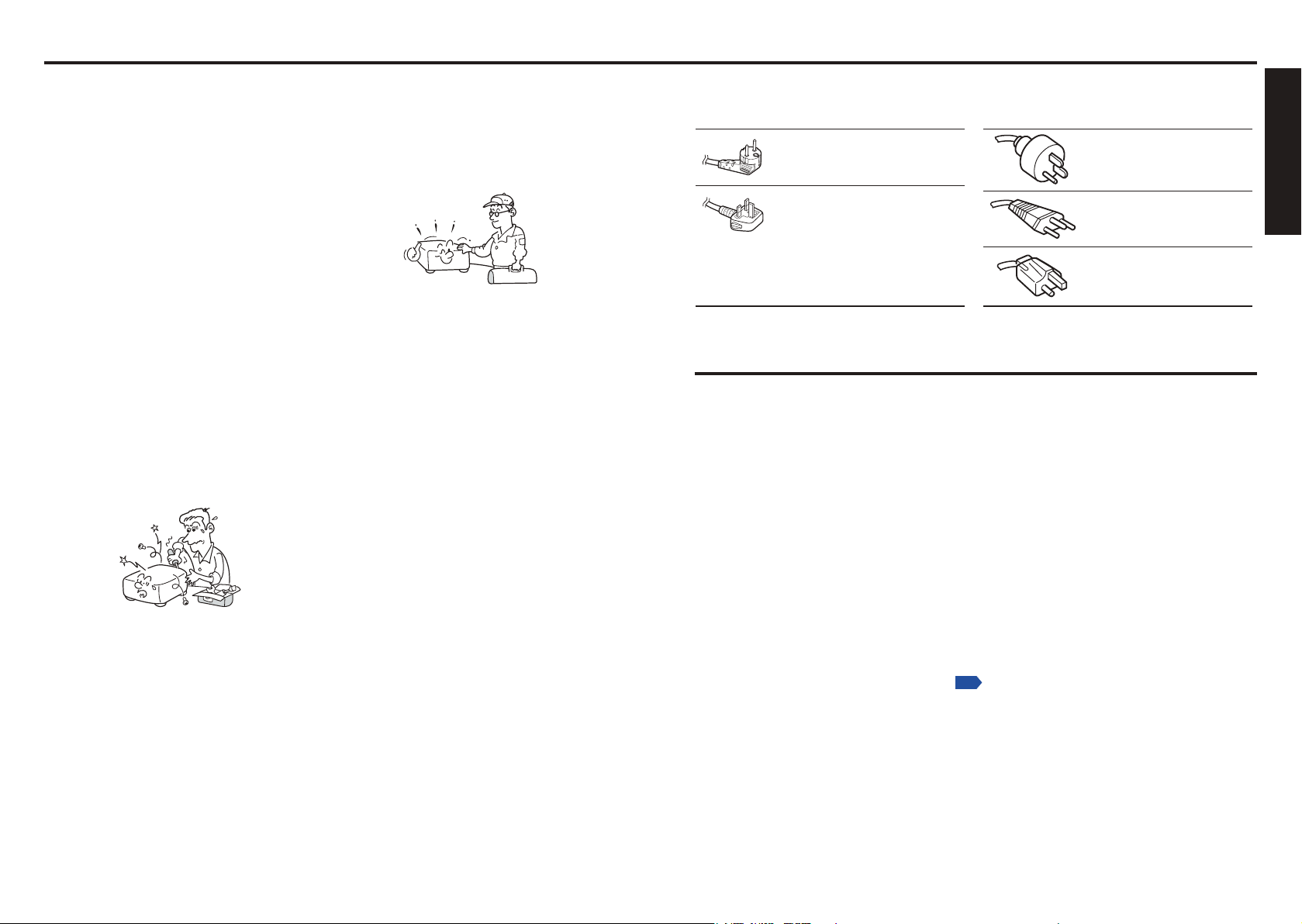
Plug
configuration
Plug type
Australian
240V
10A
North American
240V
15A
Switzerland
240V
6A
Line voltage
EURO
UK
220 – 240V
220 – 240V
200 – 240V
200 – 240V
200 – 240V
Plug
configuration
Plug type Line voltage
Use a 5A fuse which is approved by ASTA
or BSI to BSI362.
Always replace the fuse cover after
changing the fuse.
p.58
POWER SUPPLY INFORMATION
20. If glass components, including
lens and lamp, should break,
contact your dealer for repair
service.
This product incorporates glass
components, including a lens and
a lamp. If such parts should break,
please handle with care to avoid
injury and contact your dealer for
repair service. The broken pieces
of glass may cause to injury. In the
unlikely event of the lamp rupturing,
thoroughly clean the area around
the projector and discard any edible
items placed in that area.
21. Servicing
Do not attempt to service this
product yourself as opening or
removing covers may expose you to
dangerous voltage or other hazards.
Refer all servicing to qualified service
personnel.
22. Replacement Parts
When replacement parts are
required, be sure the service
technician has used replacement
parts specied by the manufacturer
or have the same characteristics as
the original part.
Unauthorized substitutions may
result in re, electric shock, or
other hazards.
23. Safety Check
Upon completion of any service
or repairs to this product, ask the
service technician to perform safety
checks to determine that the product
is in proper operating condition.
24. Do not leave thermal-paper
documents or easily deformed
items on top of the unit or
near the air exhaust for long
periods of time.
The heat from the unit could erase
the information on the thermal
paper, or cause deformation or
warping.
25. Do not use the product in a
closed installation state.
Do not place the product in a box
or in any other closed installation
state. Otherwise it may overheat. This
could result in a risk of re.
If your line voltage is 220 to 240V, use one of the following types of cable/plug.
IMPORTANT PRECAUTIONS
Moisture Condensation
Never operate this unit immediately after moving it from a cold location to a warm location.
When the unit is exposed to such a change in temperature, moisture may condense on the lens
and the crucial internal parts. To prevent the unit from possible damage, do not use the unit for
at least 2 hours when there is an extreme or sudden change in temperature.
Place and Manner of Installation
•
Do not place in hot locations, such as near heating equipment. Doing so could cause
malfunction, and shorten the life of the projector.
•
Avoid locations with oil or cigarette smoke. Doing so will dirty the optical parts, shortening
their lives, and darkening the screen.
•
Do not use this product in the upright position or tilt it up or down by more than 20° from
level. Doing so may cause a failure or shorten the life of the product.
•
Using this instrument near a TV or radio may cause interference to the images or audio
sound. If this happens, move it away from the TV or radio.
•
In a high altitude location where air is thin, cooling efciency is reduced so use the
projector with [Fan mode] set to [High].
•
Only plug the power cord into outlets rated for use with the power cord’s specied voltage
range. Do not overload extension cords or table taps as this can result in re or electric
shock.
•
Route the power cable or the connecting cable away from where people could trip over it.
The projector may fall down, which could result in severe injury.
•
Be sure the power cord is easily reached for unplugging in case of emergency. Do not
place any obstacles near a wall outlet in which the cord is plugged.
Page 6

10
11
Before Using
IMPORTANT PRECAUTIONS (Continued)
p.36
OTHER INFORMATION
Avoid Volatile Liquid
Do not use volatile liquids, such as an insect spray, near the unit. Do not leave rubber or plastic
products touching the unit for a long time. They will leave marks on the nish.
Do not use a chemically saturated cloth.
EXEMPTION CLAUSES
•
Toshiba Corporation bears no responsibility in the case of damages arising from natural
disaster such as earthquakes, lightning, etc., re not liable to Toshiba Corporation, acts
by third parties, other accidents, or use under abnormal conditions including erroneous or
improper operation and other problems.
•
Toshiba Corporation bears no responsibility for incidental damages (lost prot, work
interruption, corruption or loss of the memory contents, etc.) arising from the use of or the
inability to use this unit.
•
Toshiba Corporation accepts no liability whatsoever for any damages arising from not
having followed the descriptions in this Instruction Manual.
•
Toshiba Corporation accepts no liability whatsoever for any damages arising from
malfunctions arising from combination with equipment or software that is not related to
Toshiba Corporation.
Copyrights
Showing or transmitting commercial imaging software or broadcast or cable-broad casting
programs with the purpose of other than the personal and private viewing, including
modifying images using the freeze function, or displaying with the varying aspect ratio
of the images, could violate the direct or indirect copyrights of the imaging software or
broadcast program, etc., if done without rst consulting with the copyright holder. For this
reason, please take appropriate measures before performing one of the actions listed
above, including obtaining a license from the copyright holder.
Disposal
This product contains substances which are harmful to humans and the environment.
•
The lamp contains mercury.
Please dispose of this product or used lamps in accordance with local regulations.
Following information is only for EU-member states:
The use of the symbol indicates that this product may not be treated as
household waste. By ensuring this product is disposed of correctly, you will
help prevent potential negative consequences for the environment and human
health, which could otherwise be caused by inappropriate waste handling of
this product. For more detailed information about recycling of this product,
please contact your local city ofce, your household waste disposal service or
the shop where you purchased the product.
Trademarks
•
VGA, SVGA, XGA, SXGA, UXGA, and WXGA are trademarks or registered trademarks
of International Business Machines Corporation.
®
•
DLP
(Digital Light Processing) is a registered trademark of Texas Instruments, Inc.
•
Macintosh is a registered trademark of Apple Computer, Inc.
•
Windows is a registered trademark of Microsoft Corporation in the U.S. and other
countries.
•
Adobe is a registered trademark and Acrobat Reader is a trademark of Adobe Systems
Incorporated.
•
All other brand and product names are trademarks or registered trademarks of their
respective companies.
In the spaces provided below, record the Model and Serial No. located at the bottom of your
projector.
Model No.
Retain this information for future reference.
Serial No.
Notational Conventions Used in This Manual
•
References to pages with related information are annotated as follows.
For example, if making a reference to page 36:
•
The illustrations in this document are for reference purposes only and may not reect
your package exactly.
Page 7

REMOTE CONTROL BATTERIES
Caution
•
Never throw batteries into a re.
Using the batteries improperly may cause them to explode or leak and lead to burn or
injury. If battery-leaking uid contacts skin, wash the uid off immediately with clean water
and consult a doctor. If the uid is spilt on an instrument, avoid contact and wipe it off using
tissue paper. (Dispose of the used tissue paper as ammable garbage after moistening
with water.)
Notes
•
Be sure to use AAA (LR03) size batteries.
•
Dispose of batteries in a designated disposal area.
•
Attention should be drawn to the environmental aspects of battery disposal.
•
Do not mix different battery types or combine used batteries with new ones.
•
If the remote control does not operate correctly, or if the operating range becomes
reduced, replace both batteries with new ones.
•
If the batteries are dead or if you will not be using the remote control for a long time,
remove the batteries to prevent battery acid from leaking into the battery compartment.
•
Following information is only for EU-member states:
[Disposal of batteries and/or accumulators]
The crossed out wheeled dust bin symbol indicates that batteries
and/or accumulators must be collected and disposed of separately from
household waste.
If the battery or accumulator contains more than the specied values
of lead (Pb), mercury (Hg), and/or cadmium (Cd) dened in the Battery
Directive (2006/66/EC), then the chemical symbols for lead (Pb),
mercury (Hg) and/or cadmium (Cd) will appear below the crossed out
wheeled dust bin symbol.
By participating in separate collection of batteries, you will help to
assure the proper disposal of products and batteries and thus help
to prevent potential negative consequences for the environment and
human health.
For more detailed information about the collection and recycling
programmes available in your country, please contact your local city
ofce or the shop where you purchased the product.
EU
Hg Cd Pb
12
Page 8

14
15
Before Using
CONTENTS
Before Using
SAFETY PRECAUTIONS .............................................................................2
IMPORTANT SAFETY INSTRUCTIONS ...................................................... 4
POWER SUPPLY INFORMATION ...............................................................9
IMPORTANT PRECAUTIONS ...................................................................... 9
EXEMPTION CLAUSES ............................................................................. 10
OTHER INFORMATION ............................................................................. 11
REMOTE CONTROL BATTERIES .............................................................12
CONTENTS ................................................................................................ 14
Preparations
Checking the package contents .................................................................. 16
Introduction to the projector ........................................................................ 17
Features you will enjoy: ........................................................................... 17
Names of each part on the main unit .......................................................... 18
Carrying the projector .................................................................................. 19
Names of each part on the control panel and remote control ..................... 20
Names of the connector panel terminals ..................................................... 22
Preparing and using the remote control ...................................................... 23
Operating a computer using the remote control .......................................... 24
Placement ................................................................................................... 25
Projection distance and size ....................................................................... 26
Connection .................................................................................................. 28
Installing or removing the projection lens .................................................... 30
Removing the lens from the projector ...................................................... 30
Installing the new lens ............................................................................. 31
Securing the lens using the anti-theft screw ............................................ 32
Installing the optional color wheel (provided) .............................................. 32
Storing unused color wheel ..................................................................... 34
Operations
Turning the power on and off ...................................................................... 36
Basic operations .......................................................................................... 38
Using handy features .................................................................................. 42
Using auto setting (computer input only) ................................................. 42
Correcting the keystone distortion ........................................................... 42
Cutting off the picture and sound temporarily (Mute) ............................... 43
Changing picture mode ............................................................................ 43
Changing screen size .............................................................................. 43
Freezing the image (Freeze) ................................................................... 44
Setting the password ............................................................................... 44
Menu tree .................................................................................................... 46
Using the Adjust menus ............................................................................. 50
The Image adjustment menu ................................................................... 50
The Display setting menu ........................................................................ 53
The Advanced menu ................................................................................ 54
Using the Setting menus ............................................................................. 55
The Setting 1 menu ................................................................................. 55
The Setting 2 menu ................................................................................. 56
The Setting 3 menu ................................................................................. 58
Using the Status display screen .................................................................. 59
The Usage time screen ............................................................................ 59
The Input screen ...................................................................................... 59
The Network screen ................................................................................. 60
The Version screen .................................................................................. 60
Operation using an HTTP browser .............................................................. 61
Overview .................................................................................................. 61
Preparation before use ............................................................................ 61
Handling of the address for operation by using a browser ...................... 61
Conguring network settings ................................................................... 62
Structure of the HTTP Server .................................................................. 63
Maintenance
About the lamps .......................................................................................... 64
Replacing the lamps .................................................................................... 65
Resetting the lamp hours counter ............................................................ 68
Lens and main unit cleaning ....................................................................... 70
Cleaning the lters ................................................................................... 7
Replacing the lters ..................................................................................... 72
Resetting the lter time counter ............................................................... 73
Others
Trouble indications ...................................................................................... 74
ON/STANDY LED .................................................................................... 74
Status LED ............................................................................................... 74
Lamp LEDs .............................................................................................. 74
Before calling service personnel ................................................................. 75
Specications .............................................................................................. 76
Screen Trigger ......................................................................................... 80
1
Page 9
16
17
Preparations
Preparations
p.
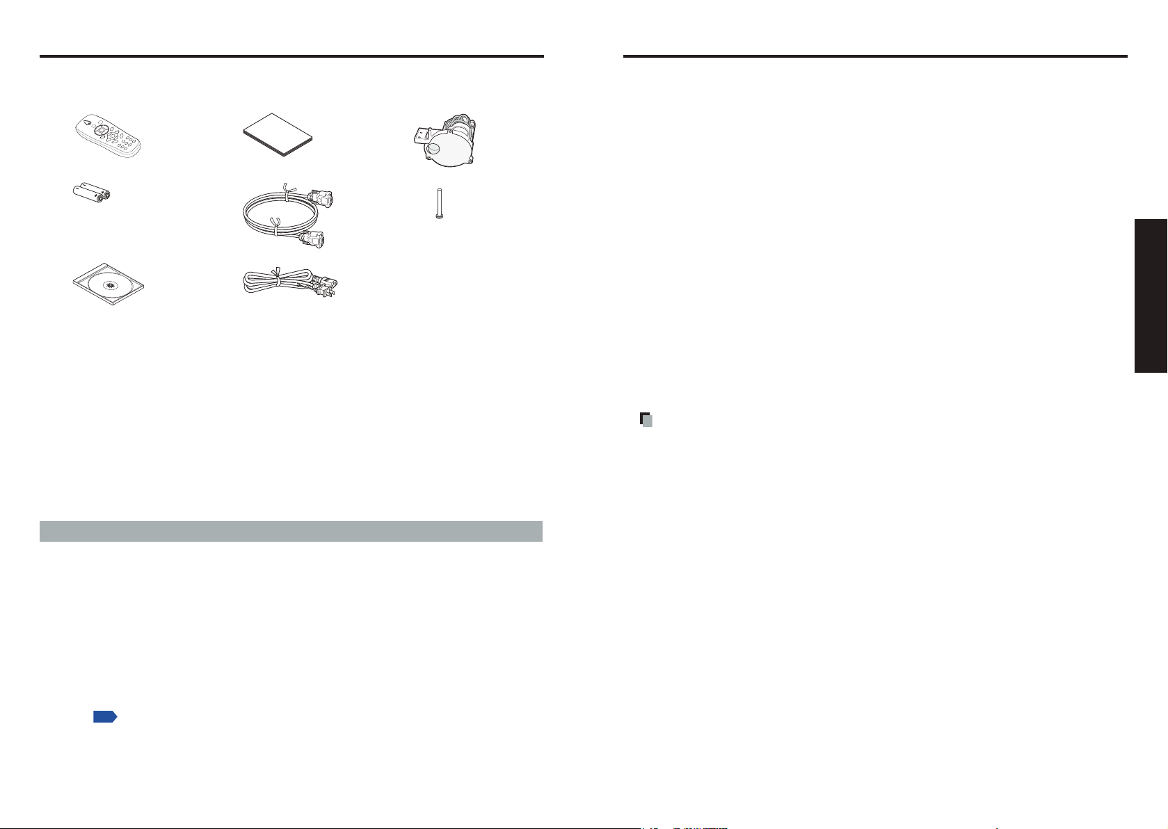
Checking the package contents
Please make sure that the following items are included in the box, along with the main unit. If any
item is missing, immediately contact the store where you purchased the product.
(1) (4) (7)
(2) (5) (8)
(3) (6)
£
(1) Remote control
£
(2) LR03 (SIZE AAA) batteries for remote control (2)
£
(3) CD-ROM
£
(4)
Owner’s Manual
Note
1. To maintain original performance, always use the supplied cables.
2. The shape and number of supplied power cords vary depending on the product destination.
£
(5)
RGB cable (1.8m)
£
(6)
Power cord
£
(7)
Six segment color wheel
£
(8)
Lens anti-theft screw
Save Original Packing Materials
The original shipping carton and packing materials will come in handy if you ever have to ship
your projector. For maximum protection when shipping your projector, repack the set as it was
originally packed at the factory.
The Supplied CD-ROM
The supplied CD-ROM contains an owner’s manual in Portable Document Format (PDF).
Please use Acrobat Reader 5 or later version to view the manual.
Adobe® Acrobat® Reader® or Adobe® Reader
The supplied CD-ROM does not contain Acrobat® Reader®. If you cannot read PDF les,
please install Adobe Reader software in your computer by downloading it from Adobe
Systems website.
Viewing the Manual
Run the CD-ROM and double-click on Start.pdf. Acrobat® Reader® launches, and the menu
screen of the owner’s manual appears. Click on your language. The Owner’s Manual cover
and list of bookmarks appears. Click on a bookmark title to view that section of the manual.
Click on
See the Help menu for more information about Acrobat
to view a reference page with related information.
®
®
Reader®.
(see note 1)
(see note 1,2)
Introduction to the projector
Features you will enjoy:
•
DLP projector with high resolution
•
Native WXGA support
A WXGA (1280 x 800) resolution provides wide screen display with an aspect ratio of 15:9.
•
High brightness
H
igh brightness output of 5200 and 4500 lumens is achieved using the 4-segment color
wheel.
•
Dual Lamp system
T
wo-lamp system offers increased lamp life and energy savings along with redundancy.
•
Extensive projection lens with bayonet mount
•
Powered Lens Shift, Zoom, and Focus offer installation exibility
Powered Horizontal and Vertical lens shift provides the ability to project from off center
screen installations. Powered zoom and focus provide quick and easy adjustment.
•
Direct Power Off & Auto Start
The projector has a feature called “Direct Power Off”. This feature allows the projector
to be turned off (even when projecting an image) using a power strip equipped with a
switch and a breaker.
Note
• Before using Direct Power Off, be sure to allow at least 20 minutes right after turning
on the projector and before starting to display an image. Also, the power cable can be
removed immediately after turning off the projector. Auto Start eliminates the need to
always turn off the projector by the ON/STANDBY button on the remote control or projector
cabinet.
•
A variety of input ports and a comprehensive array of system control interfaces
This projector supports input signals including BNC, DVI-D, analog RGB, component,
S-video, and composite.
•
3W+3W Stereo speakers
Built in 3W x 2 speakers are provided.
•
Prevent unauthorized use of the projector
nhanced smart security settings for password protection, cabinet control panel lock to
E
help prevent unauthorized access, adjustments and theft deterrence.
•
Integrated RJ-45 connector for wired networking capability for property management
•
Combination of BrilliantColor™ and 6-segment color wheel offers true color reproduction
Page 10
18
19
Preparations
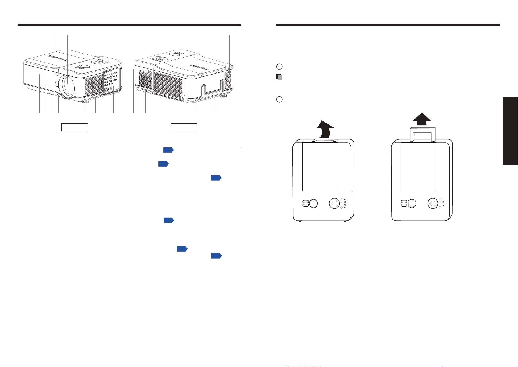
Names of each part on the main unit
(1) (2) (3) (4)
(7)(8)
(5)(6) (10)(9) (11) (12) (14) (15) (16)(13) (17)
p.65
p.20
p.23
p.39
p.22
p.23
Front Back
Name : Function
(1) Lamp cover :
(2) Lens : Remove lens cap before use.
(3) Control panel :
(4) Speaker :
(5) Front IR Receiver :
(6) Lens release button : Press the release button before removing the lens.
(7) Intake vent and front lter :
(8) Anti-theft screw : Prevents theft of the lens.
(9) Foot adjuster :
(10) Right lter :
(11) Connector panel :
(12) Rear IR Receiver :
(13) Rear lter :
(14) Air exhaust : Expels air that has grown hot inside the projector—do not
(
15
) Kensington lock : Attach the projector to a permanent object with the
(
16
) Security chain lock : Attach the projector to a permanent object using a security
(
17
) Carrying handle : Pull up the handle when carrying the projector.
Remove to replace lamp.
Operates the projector.
Outputs audio sound.
Receives IR signals from the remote control.
Keeps the front fan free of dust.
•
Clean regularly for optimum performance.
•
Do not obstruct.
Adjusts level of projector.
Keeps the right fan free of dust.
•
Clean regularly for optimum performance.
•
Do not obstruct.
Connect various input devices.
Receives IR signals from the remote control.
Keeps the rear fan free of dust.
•
Clean regularly for optimum performance.
•
Do not obstruct.
obstruct.
Kensington slot and a security cable.
cable.
Carrying the projector
Always carry your projector by the handle.
Before moving or carrying the projector, disconnect the power cable and any other cables that
may be attached to it.
When moving the projector or when the projector is not in use, cover the lens with the lens cap.
To extend the projector handle, refer to the following guide.
1
Stand the projector on its end with the panel terminal facing to the bottom.
Note
•
Stand the projector on its end by lifting the cabinet. Do not use the handle to place the
projector upright.
2
Lift the handle in the direction shown until it is fully extended.
Page 11
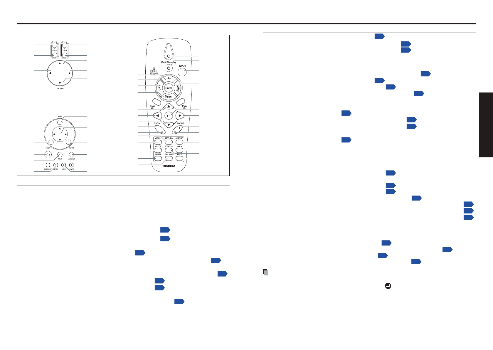
Names of each part on the control panel and remote control
(1)
(1)
(2)
(6)
(7)
(3)
(4)(8)
(6)
(7)(20)
(21)
(8)
(5)
(2)
(3)
(4)
(5)
(18)
(19)
(9)
(9)
(22)
(23)
(24)
(10)
(11)
(12)
(10)(25)
(11)(26)
(12)
(15)
(16)
(17)
(13)
(13)(27)
(28)
(14)
(15)
(16)
(17)
(14)
(18)
(19)
p.39
p.39
p.46
p.46
p.42
p.74
p.74
p.36
p.38
p.74
p.74
p.36
p.38
p.24
p.24
p.46
p.39
p.39
p.42
p.24
p.24
p.24
p.24
p.46
p.46
p.46
p.46
p.43
p.44
p.39
Name : Main Function
Control panel
(1)
ZOOM + button
(2)
ZOOM – button
(3)
UP SHIFT button
RIGHT SHIFT button : Move images right.
(4)
DOWN SHIFT button :
(5)
FOCUS + button :
(6)
(7)
FOCUS – button
(8)
LEFT SHIFT button
(9)
MENU button
(10) Selection button
(11) RETURN button
(12) AUTOSET button :
(13) LAMP 2 :
(14) LAMP 1
(15) ENTER button
(16)
ON/STANDBY button
Remote ControlControl panel
:
Adjusts the screen size.
:
Adjusts the screen size.
:
Move images up.
Move images down.
Focus the projected image.
:
Focus the projected image.
: Move images left.
:
Displays menus.
:
Menu selections and adjustments, volume control, etc.
: Goes back one screen.
Performs auto-adjustment of input signals from computer.
See Indicator Messages.
:
See Indicator Messages.
:
Accepts the selected mode.
Turns the power on/off (standby).
:
20 21
Name : Main Function
(17) INPUT button :
Selects input.
(18) ON/STANDBY (LED) : See Indicator Messages.
(19) STATUS (LED) : See Indicator Messages.
Remote control
(1) Status LED : Lights when the remote control is used.
(2) ON/STANDBY button :
(3) INPUT button :
(4)
Cursor control button (Right)
(5) Page Dn button : Proceeds PowerPoint® slides.
(6) ENTER button : Executes menu operations, etc.
(7) Selection button (Right) : Menu selections and adjustments, volume control, etc.
(8) FOCUS + button :
(9) FOCUS – button :
(10) AUTOSET button :
(11) Vol + button : Ajusts the volume.
(12) STATUS button : Opens the OSD Status menu (the menu only opens when
(13) Vol – button : Ajusts the volume.
(14) Cursor control button (Up) : Controls a Cursor.
(15) ENTER button : Accepts the selected mode.
(16) Cursor control button (Left): Controls a Cursor.
(17)
Cursor control button (Down)
(18) Page Up button : Reviews PowerPoint® slides.
(19) Selection button (Up) :
(20) Selection button (Left) :
(21) Selection button (Down) :
(22) ZOOM + button : Adjusts the screen size.
(23) ZOOM – button : Adjusts the screen size.
(24) RETURN button : Goes back one screen.
(25) MENU button :
(26) MUTE button : Cuts off the picture and sound temporarily.
(27) FREEZE button : Pauses image.
(28) LENS SHIFT button : Displays the lens shit screen.
Note
•
For the remainder of this manual, buttons are referred to as follows:
Selection buttons
pqtu
⇒
Turns the power on/off (standby).
Selects input.
:
Controls a Cursor.
Focus the projected image.
Focus the projected image.
Performs auto-adjustment of input signals from computer.
an input device is detected).
:
Controls a Cursor.
Menu selections and adjustments, volume control, etc.
Menu selections and adjustments, volume control, etc.
Menu selections and adjustments, volume control, etc.
Displays menus
.
; ENTER button ⇒
Preparations
Page 12
22
23
Preparations
Names of the connector panel terminals
(11)(12)(13)(14)(15)(16)(19) (18)(17)
(8)(6) (7)(5)(4)(3) (10)(9)(2)(1)
p.79
p.80
Approx. 15°
Approx. 7m
Preparing and using the remote control
Name : Main Function
(1) COMPUTER 1 IN : Connect a VGA cable from a computer.
(2) LAN : Connect a LAN cable from a computer.
(3) USB :
(4) AUDIO IN (1) : Connect the audio cable from the input device.
(5) COMPUTER 3 IN :
(6) AUDIO IN (3) : Connect the audio cable from the input device.
(7)
AUDIO OUT
(8) MONITOR OUT : Connect a monitor.
(9)
AUDIO IN (2)
(
10
) RS232C terminal :
(11) SCREEN TRIGGER : When connected to the screen through a commercially
(12) Main power switch : Turn on/off the projector.
(
13
) S-VIDEO : Connect a commercially available S-video cable from a video
(
14
) L/MONO, R
(Component)
(
15
) AC IN : Connect the supplied power cable.
(
16
) L/MONO, R (Video) : Connect RCA audio cables from the input device right and
(
17
) VIDEO IN : Connect a composite video cable from a video device to the
(
18
) COMPONENT IN
(Y, Cb/Pb, Cr/Pr)
19
) COMPUTER 2 IN
(
(R/PR, G/Y, B/PB, H, V)
Connect the USB cable from a computer for rmware
upgrades or keypad remote emulation.
Connect the DVI cable from a computer.
: Audio loop through.
: Connect the audio cable from the input device.
When operating the projector via a computer, connect this
to the controlling computer’s RS-232C port
available cable, the screen deploys automatically on
start up of the projector. The screen retracts when the
projector is powered off.
device.
: Connect an RCA audio cables from the input device right and
left channels.
left channels.
This audio jack is shared with S-Video input.
yellow RCA jack.
: Connect a component video enabled device.
: Connect RGBHV or Component signal from computer or
component video enabled device.
.
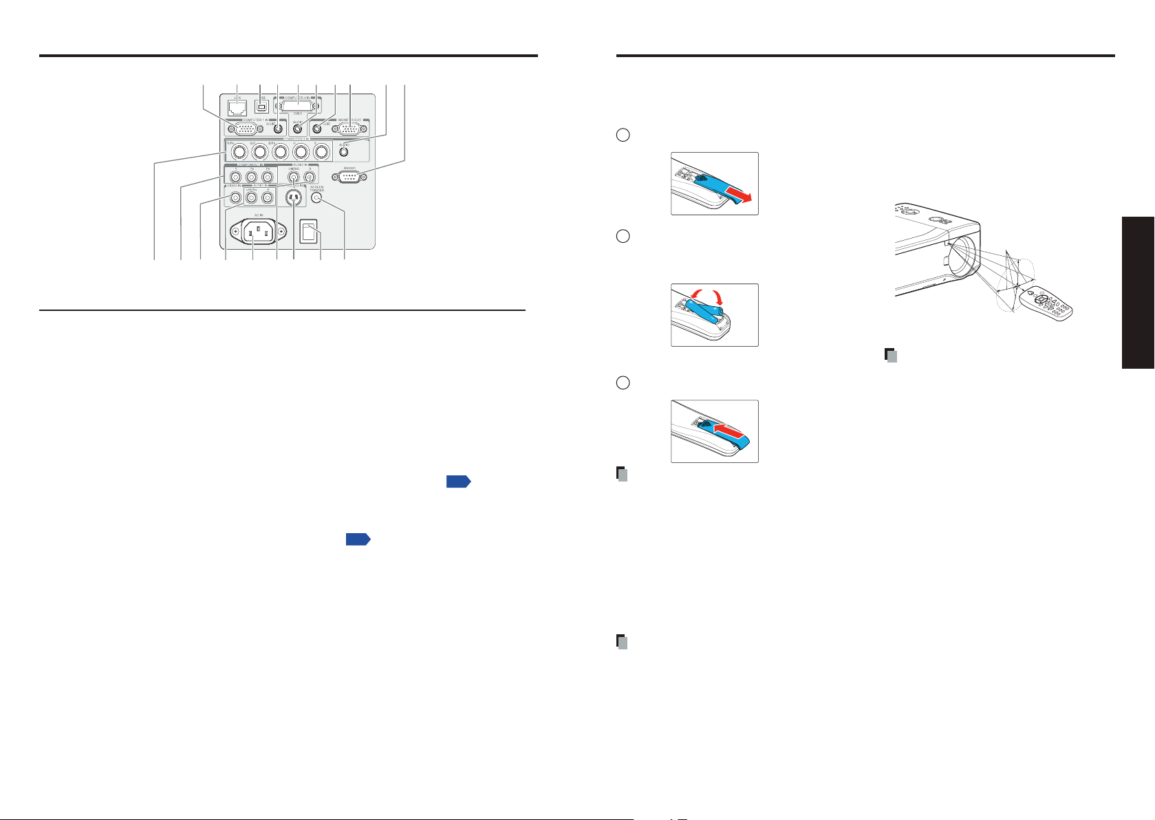
Loading dry-cell
batteries
into the remote control
1
Remove the battery cover.
2
Insert the dry-cell batteries.
Be sure to align the plus and minus ends of
the batteries properly.
Two batteries (LR03, SIZE AAA) are used.
3
Replace the battery cover.
Dry-cell batteries
•
Before using the batteries, be sure to observe the Safety Precautions described in previous pages.
•
If the remote control stops working, or if its range decreases, replace all the batteries with new
ones. (2 batteries (LR03 SIZE AAA))
•
Do not heat, take apart, or throw batteries into re.
•
Do not use new and old batteries together, or different types of batteries together.
•
Dispose of used batteries according to local regulations.
•
Remove batteries from remote control when not using for extended periods.
•
Keep the batteries away from the reach of children.
Batteries are choking hazards and can be very dangerous if swallowed. If the batteries are
swallowed, seek medical assistance immediately.
The remote control
•
Avoid exposing the remote control infrared sensor to bright sunlight or uorescent lighting.
•
Do not drop or bang.
•
Do not leave in hot or humid locations.
•
Do not allow it to get wet or place it on top of wet objects.
•
Do not take it apart.
•
Ensure that the battery polarities (+/–) are aligned correctly.
•
In rare cases, ambient conditions could impede the operation of the remote control. If this
happens, point the remote control at the main unit again, and repeat the operation.
Operating the remote
control
Point toward the projector’s infrared
remote sensor, and press a button
on the remote control.
•
Operating the projector from the front
Note
•
The above operation is also applicable
for the remote control operation from
rear side.
Page 13
24
25
Preparations
Operating a computer using the remote control
1
To USB port
2
p.56
Placement
A computer can be operated using the projector’s remote control. This function is available
on any computer with the Windows
Windows Vista
function is also supported on OS 9 or MAC OS X for the Macintosh). However, please note that
Toshiba does not guarantee the operation of all computers.
®
operating system, that is equipped with a USB port which can support USB1.1 (This
®
98/98SE, Windows® Me, Windows® 2000, Windows® XP, or
Connecting a computer
Connect a USB cable (not supplied) from the projector to a computer.
Operating a computer
Operate remote control’s buttons towards the projector’s IR receiver.
Moving the cursor
Press the keyboard function buttons (cursor control buttons) in the direction you wish the
cursor to move.
Using the computer’s page up [#] and down [$] function
Press the Page Up and Page Dn buttons to switch PowerPoint
®
slides.
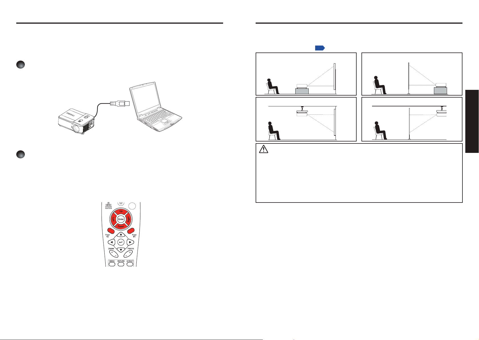
Placement Styles
As shown in the gures below, this device can be placed in 4 different styles.
The factory setting is “oor-mounted front projection.” Set [Projection mode] in the
Setting - Setting 2 menu
Floor-mounted front projection
Ceiling-mounted front projection
WARNING
•
Always obey the instructions listed in IMPORTANT SAFETY INSTRUCTIONS when placing
the unit. Attempting to clean and replace the lamp in a high location by yourself may cause
you to fall, resulting in injury.
•
If you wish to mount the projector on the ceiling, be sure to ask your dealer to do so.
Mounting the projector on a ceiling requires special ceiling brackets (sold separately) and
specialized knowledge. Improper mounting could cause the projector to fall, resulting in
possible injury and unit damage.
•
If the projector is ceiling-mounted, install the breaker for turning off the power in case of
anomaly. Let everyone involved with the use of the projector know that fact.
, in accordance with your needs.
Floor-mounted rear projection
Ceiling-mounted rear projection
Page 14

Projection distance and size
(Reference: TLPNL54)
1.53 m
1.02 m
1.27 m
1.52 m
2.03 m
2.54 m
1.92 m 2.3 m 3.07 m 3.83 m
p.39
p.25
Use the gures and tables below to determine the projection size and projection distance.
(Projection sizes are approximate values for full-size picture with no keystone adjustment).
A
is the distance between the lens and the screen.
Example of TLPNL54:
The further your projector is away from the screen or wall, the larger the image becomes. The minimum
size the image is approximately 40 inches (1.02 m) measured diagonally when the projector is in the
distance of 60.2 inches (1.53 m) from the wall or screen. The largest the image can be is 500 inches
(12.70 m) when the projector is in the distance of 754.7 inches (19.17 m) from the wall or screen.
Lens
Screen Size
Diagonal Width Height (B)
[inches] [m] [inches] [m] [inches] [m] [inches] [m] [inches] [m] [inches] [m] [inches] [m] [inches] [m] [inches] [m]
40 1.02 33.9 0.86 21.3 0.54 - - - - 45.3 1.15 60.6 1.54 60.2 1.53 79.5 2.02
50 1.27 42.6 1.08 26.4 0.67 32.7 0.83 - - 56.3 1.43 76.0 1.93 75.6 1.92 99.6 2.53
60 1.52 50.9 1.29 31.9 0.81 39.4 1 - - 67.7 1.72 90.9 2.31 90.6 2.3 119.7 3.04
80 2.03 67.8 1.72 42.6 1.08 52.4 1.33 - - 90.2 2.29 121.3 3.08 120.9 3.07 159.4 4.05
100 2.54 84.8 2.15 53.2 1.35 65.7 1.67 - - 112.6 2.86 152.0 3.86 150.8 3.83 199.2 5.06
120 3.05 101.7 2.58 63.9 1.62 78.7 2 - - 135.4 3.44 182.3 4.63 181.1 4.6 239.0 6.07
150 3.81 127.3 3.23 79.6 2.02 98.4 2.5 - - 169.3 4.3 227.6 5.78 226.4 5.75 298.8 7.59
180 4.57 153.0 3.88 95.4 2.42 118.1 3 - - 203.1 5.16 273.2 6.94 271.7 6.9 358.7 9.11
200 5.08 170.0 4.31 106.0 2.69 131.1 3.33 - - 225.6 5.73 303.5 7.71 302.0 7.67 398.4 10.12
300 7.62 254.7 6.46 159.4 4.04 - - - - 338.2 8.59 455.5 11.57 452.8 11.5 598.0 15.19
400 10.16 339.8 8.62 212.2 5.38 - - - - 451.2 11.46 607.1 15.42 603.9 15.34 797.2 20.25
500 12.70 424.6 10.77 265.5 6.73 - - - - 563.8 14.32 759.1 19.28 754.7 19.17 996.5 25.31
TLPSFL54 TLPSL54 TLPNL54
Distance (A)
WIDE TELE WIDE TELE WIDE TELE
Lens
Screen Size
Diagonal Width Height (B)
[inches] [m] [inches] [m] [inches] [m] [inches] [m] [inches] [m] [inches] [m] [inches] [m]
40 1.02 33.9 0.86 21.3 0.54 75.2 1.91 150.4 3.82 150.4 3.82 281.5 7.15
50 1.27 42.6 1.08 26.4 0.67 94.1 2.39 187.8 4.77 187.8 4.77 352.0 8.94
60 1.52 50.9 1.29 31.9 0.81 113.0 2.87 225.6 5.73 225.6 5.73 422.4 10.73
80 2.03 67.8 1.72 42.6 1.08 150.8 3.83 300.4 7.63 300.4 7.63 563.0 14.3
100 2.54 84.8 2.15 53.2 1.35 188.2 4.78 375.6 9.54 375.6 9.54 703.9 17.88
120 3.05 101.7 2.58 63.9 1.62 226.0 5.74 450.8 11.45 450.8 11.45 844.5 21.45
150 3.81 127.3 3.23 79.6 2.02 282.3 7.17 563.4 14.31 563.4 14.31 1055.9 26.82
180 4.57 153.0 3.88 95.4 2.42 339.0 8.61 676.4 17.18 676.4 17.18 1266.9 32.18
200 5.08 170.0 4.31 106.0 2.69 376.4 9.56 751.2 19.08 751.2 19.08 1407.9 35.76
300 7.62 254.7 6.46 159.4 4.04 565.0 14.35 1127.2 28.63 1127.2 28.63 2111.4 53.63
400 10.16 339.8 8.62 212.2 5.38 753.1 19.13 1502.8 38.17 1502.8 38.17 2815.4 71.51
500 12.70 424.6 10.77 265.5 6.73 941.3 23.91 1878.3 47.71 1878.3 47.71 3519.3 89.39
TLPML54 TLPLL54
Distance (A)
WIDE TELE WIDE TELE
For your reference, the throw distance can be also obtained by the following formulas.
Throw Distance
Lens [Inches] [Meters]
TLPSFL54
[Notes 1]
B × 0.817 - 1.535 B × 0.817 - 0.039
TLPSL54 B × 1.379 - 1.969 through B × 1.854 - 1.811 B × 1.379 - 0.050 through B × 1.854 - 0.046
TLPNL54 B × 1.844 - 2.362 through B × 2.435 - 2.48 B × 1.844 - 0.060 through B × 2.435 - 0.063
TLPML54 B × 2.328 - 4.134 through B × 4.639 - 4.173 B × 2.328 - 0.105 through B × 4.639 - 0.106
TLPLL54 B × 4.580 - 5.433 through B × 8.604 - 5.354 B × 4.580 - 0.138 through B × 8.604 - 0.136
* “B” means the screen width.
Notes
•
TLPSFL54 is guaranteed the performance only when the Lens Shift is set to 0%. Ensure
to adjust the Lens Shift
the gure on
.
as the Lens center comes at the Screen center shown in
Preparations
26 27
Page 15

Connection
p.78
Before connection
•
Read the owner’s manual of the device you are connecting to the projector.
•
Some computers cannot be used or connected to this projector.
Check for an RGB output terminal and supported signal
•
Turn off the power of both devices before connecting.
.
Notes
•
The COMPUTER 1 IN terminal functions identically to the COMPUTER 2 and 3 IN
terminals.
•
The MONITOR OUT connector will output no video signal (Digital signal) from the
COMPUTER 3 IN connector. If no input is selected, the MONITOR OUT terminal
outputs the input signals last selected for each input terminal.
•
Signals are output from MONITOR OUT terminal even in standby mode.
However, from AUDIO OUT terminal, no audio signal is output.
A computer monitor cannot accept Y/P
•
•
The AUDIO IN 1, 2, and 3 terminals double for devices connected to COMPUTER
terminals 1, 2, and 3.
•
When an AUDIO OUT terminal is connected, sound is not output from the projector
speaker.
•
Output volume of AUDIO OUT terminal can be adjusted by the VOL button.
B/PR signals correctly.
Preparations
28 29
Page 16

Installing or removing the projection lens
Arrow Mark
CAUTION:
•
Do not shake or apply excessive pressure on the projector or the lens components as
the projector and lens components contain precision parts.
•
When shipping the projector with the projection lens, remove the projection lens before
shipping the projector. Improper handling during transportation may cause damage to
the lens and the lens shift mechanism.
•
Before removing or installing the lens, be sure to turn off the projector, wait until the cooling
fans stop, and turn off the main power switch.
•
Do not touch the lens surface when removing or installing the lens.
•
Keep ngerprints, dust or oil off the lens surface. Do not scratch the lens surface.
•
Work on a level surface with a soft cloth under it to avoid scratching.
•
If you remove and store the lens, attach the cap to the projector to keep off dust and
dirt.
•
Do not turn on the projector when a projection lens is not mounted.
Removing the lens from the projector
1
Remove the lens cap.
2
Push the LENS RELEASE button all the way in and rotate the lens counterclockwise.
The lens will be disengaged.
3
Pull out the lens slowly.
CAUTION:
•
When Installing the projection lens into the projector, be sure to remove the lens cap
from the back of the lens before installing into the projector. Failure to do so will cause
damage to the projector.
Installing the new lens
1
Insert the lens with the arrow mark of the unit facing up.
Preparations
Note
•
If the lens cannot be removed by using the LENS RELEASE button, the anti-theft screw may be
in use to secure the lens. If that is the case, remove the anti-theft screw rst.
30 31
2
Rotate the lens clockwise until you feel it click into place.
Page 17

32
33
Preparations
Anti-theft screw hole
for lens unit
Anti-theft screw
A
B
Installing or removing the projection lens (Continued)
Securing the lens using the anti-theft screw
Using the anti-theft screw to prevent theft of the lens. Tighten the supplied anti-theft screw
on the front bottom.
3
Unscrew the retaining screws (x 4) on the four-segment color wheel.
4
Lift the color wheel in the direction shown.
Installing the optional color wheel (provided)
This projector comes with a four-segment color wheel installed. An additional six-segment color
wheel is also provided. To replace the color wheel (located under the lamp cover adjacent to
lamp 1) refer to the following guide.
Note
•
Wait until the lamp housing and the color wheel cool off.
1
Loosen the captive screw (A) on the lamp cover.
2
Remove the lamp cover by sliding it in the direction of the arrow (B).
5
Insert the six-segment color wheel.
Page 18

B
A
Installing or removing the projection lens (Continued)
6
Secure the retaining screws as shown.
7
Align the lamp cover in the direction of the arrow (A) and slide it into place.
8
Secure the captive screw (B).
Storing unused color wheel
Keep the unused color wheel in the zipper bag in which the 6-segment color wheel was
packaged.
This bag prevents dust from falling or collecting on the color wheel.
34
Page 19

36
37
Operations
1
2
1
2
3
4
5
6
Operations
ON/STANDBY STATUS LAMP1 LAMP2
ON/STANDBY STATUS LAMP1 LAMP2
ON/STANDBY S TATUS LAMP1 LAMP2
p.56
p.45
1
2
ON/STANDBY STATUS LAMP1 LAMP2
Turning the power on and off
Connecting the power cord
Insert the power cord connector into
the AC IN socket of the projector.
Insert the power cord plug into a wall
or other power outlet.
Turning the power on
Remove the lens cap.
Remove the lens cap as shown (if present).
Be sure to remove the lens cap when the power is turned on.
If the cap is left on the projector, it could become deformed
due to heat.
Power cord
connector
(supplied)
CAUTION
•
Do not look into the lens while the lamp is on. The strong light from the lamp may cause
damage to your eyesight.
•
Do not block the air intake or exhaust. Doing so could cause a re due to internal overheating.
•
Do not place your hands, face, or other objects near the air exhaust, the lamp cover or the bottom of
the unit. Doing so could result in injury and/or damage.
Notes
•
The rst time you use the projector after purchase, after the start-up screen disappears,
the start menu is displayed.
•
When [Key lock] is [On], the operation buttons of the projector do not work
•
When [Password] is [On], enter password then the start-up screen is displayed after
the Password entry screen disappears
•
Do not touch the lens directly with your hand.
If ngerprints or stains are left on the projection lens surface, they may interfere with the
projector’s ability to project images on the screen.
.
.
Turn on the main power switch.
The ON/STANDBY indicator lights orange, and the
Status indicator lights green indicating standby mode.
Press the ON/STANDY button on
the control panel or on the remote
control.
The ON/STANDBY LED lights green and the internal
cooling fan starts.
After approximately 10 seconds,
the ON/STANDBY LED ashes
intermittently green.
The LAMP1 and LAMP2 LEDs light
green and the ON/STANDY LED
ashes more rapidly.
Control panel
Remote
control
Turning the power off
Press the ON/STANDBY button on the control panel or the
remote control.
A message appears on the screen, conrming that you wish to shut off the power. This
message will disappear after a moment. (This operation is no longer valid after the
message disappears.)
Press the ON/STANDBY button again.
The screen goes blank, but the internal cooling fan
continues to operate. Then, the projector goes into
standby mode.
During cooling, the ON/STANDBY indicator ashes. While the indicator is ashing, the
power can not be turned back on. However, there is no problem with unplugging the power
cord in this state.
Note
•
The projector consumes about 5W of power in standby. We recommend that you unplug
the power cord if you will not be using the projector for an extended period.
Precaution
•
If the power cord is unplugged before cooling is complete or the main power is turned
off, give the lamp time (about 5 minutes) to cool before plugging it back in. If the lamp
overheats, it may fail to light.
Power saving mode
Power saving mode activates the standby condition consuming less power than
Standard mode. Go to the Setting-Setting 2 menu to turn on Power saving mode.
Once the ON/STANDBY, LAMP1 and LAMP2 LEDs are lit
solidly green, the projector is ready for use.
Page 20

38
39
Operations
Basic operations
1
p.36
2
p.51
3
4
5
6
7
Turn on the power.
Turn on the power by following the instructions in “Turning the power on”
Select the language (When using the rst time).
When the projector is used for the rst time after purchase, the start menu for language
selection is displayed in English. (If the screen is out of focus, adjust it according to the step 6.)
.
Projector placement angle adjustments
The placement angle and the height of the projected image can be adjusted by the
foot adjusters.
1
To raise the level of the projector, twist
the adjusters clockwise.
2
To lower the level of the projector, lift
the projector and twist the adjusters
counter clockwise.
Use the
Message for setup conrmation is displayed in a selected language.
p
button to select the desired language and press the button.
or
q
Notes
•
When the projector is turned on the next time, the start menu does not appear upon
startup. However, if [All data] is executed from the Reset menu, the start menu will
be displayed the next time when the power is turned on.
•
The language can also be set from the Setting-Setting 1 menu
•
This owner’s manual assumes that English has been selected.
.
Activate the connected device.
Turn on and start the connected device such as a computer.
Press the INPUT button.
An image of the connected equipment is projected.
Each time you press the INPUT button, it switches to the input of the connected equipment
that is outputting video signals.
Adjusting zoom and focus
1
If you wish to adjust the screen size,
2
Use the FOCUS buttons on the
Adjusting the Picture Position and
Picture Size
The Picture Position and Picture Size can be adjusted manually from the lens control panel
or from the remote control unit (LENS SHIFT button)
Adjusting Picture Position and Picture
1
Press the Select keypad in any
2
Press the directional key as required
use the ZOOM buttons on the projector
or remote to adjust the screen size.
projector or remote to adjust the focus.
Size Manually
direction to bring up the [Lens Shift]
window.
to shift the image. Releasing the
directional arrow will re-center the
cursor.
Page 21

40
41
Operations
8
Basic operations (Continued)
p.78
3
To alter the picture size,
press Menu and select the
[Adjust] menu using p or
. Press Enter to open the
q
[Adjust] menu. Press t or
to select [Display setting]
u
followed by p or q to select
[Screen]. Press Enter.
4
The [Screen] window is
displayed. Select the desired
picture size using p or q
and press Enter.
When nished, press
[Return] to go back to the
projected image.
Notes
•
Note that lamp characteristics may rarely cause the brightness to uctuate slightly.
•
A lamp is consumable item. If used for extended periods, images will appear dark, and the
lamp could burn out. This is characteristic of a lamp, and is not malfunction. (The lifetime of
the lamp depends on conditions of use.)
•
The DLP® chip is made using extremely advanced technology, but there may be black spots
(pixels that do not light) or bright spots (pixels that are constantly lit) on the panel. Please
note that these are not malfunctions.
•
Although this projector supports a wide range of RGB signals
supported by this projector (WXGA) will be expanded or shrunk, which will affect image
quality slightly. To view high-quality images, it is recommended that the computer’s
external output should be set to WXGA resolution.
•
With some models of computer having LCD displays or the like, displaying images
simultaneously on the projector and the monitor’s display may prevent the images from
displaying properly. If this happens, turn off the computer’s LCD display. For information on
how to turn off the LCD display, see the owner’s manual of your computer.
•
If no signal is being input from the connected equipment or signal input is stopped while
projecting, the “No signal” will appear.
•
If a signal not supported by the projector is input, “No signal” message will appear.
•
If an unavailable operation button is pressed, “This function is not supported” will appear.
, any resolutions not
Adjusting the volume
The volume can be adjusted with the
remote control unit.
1
Press the Vol +/- buttons
on the remote control. The
volume bar is displayed on
screen.
2
Use the Vol +/- buttons to adjust the level.
Notes
•
Volume can also be adjusted from the Volume in the Menu.
Page 22

Using handy features
p.78
p.53
1
2
Using auto setting (computer input only)
This function automatically sets up the projector to the optimum state. It sets up the
sampling phase, frequency and screen position, etc., for each type of input signal
through a simple operation.
Press the AUTOSET button.
Notes
•
The image may not be projected or auto adjustment/setting may
not be performed correctly for input signals other than those
supported by the projector
•
If auto setting fails adjustment, adjust manually through Adjust,
Display setting menu
Correcting the keystone distortion
When the projector placement angle against the screen is changed while projecting
the image, the picture will undergo keystone (trapezoidal) distortion. This projector is
capable of correcting this keystone distortion.
Before correction
.
.
After correction
Adjusting Keystone distortion
Select the Setting menu using p or
. Press Enter to open the Setting
q
menu. Press t or u to select Setting
1 followed by p or q to select
Keystone. Press Enter.
Use the t u buttons to adjust the keystone distortion.
Notes
•
Depending on the amount of keystone adjustment needed and the image content,
some information may be lost, or the picture quality may suffer.
•
The keystone correction settings are memorized after the power has been turned
off—the projector placement angle against the screen remains unchanged.
•
Some adjustments using keystone correction while displaying an input image with
a 16:9 aspect ratio, may affect displaying the menu properly. In such a case, reset
keystone correction to use the menu.
Remote
control
Cutting off the picture and sound temporarily (Mute)
When you want to project the images of another projector, overhead
projector, etc. temporarily, this projector’s images and sound can be
turned off.
Press the remote control’s MUTE button.
The picture and sound are cut off. (The Mute function is released
when pressing the MUTE button again.)
Notes
•
Operating any other functions will also cancel the muting.
•
The mute function is supported during most video and audio
playback.
Precaution
•
Do not replace the lens cap to cut off the projected image temporarily. It may cause
the lens cap to deform due to the heat.
Changing picture mode
The projected image mode can be selected.
Select the Adjust menu using p or q. Press Enter to open the Adjust
menu. Press t or u to select Image adjustment followed by p or q to
select Picture mode. Press Enter.
Press p or q to select the desired mode and press Enter.
Changing screen size
The screen size for the projected image can be changed.
Select the Adjust menu using p or q. Press Enter to open the Adjust
menu. Press t or u to select Display setting followed by p or q to select
Screen. Press Enter.
Press p or q to select the desired mode and press Enter.
Notes
•
Thru display is available for Computer and Network-input images.
•
Wide display is available for Y/P
•
Using this function on commercial video software, broadcast or cable-broadcasting
except for the purpose of your private viewing and listening may infringe the
copyright protected by the copyright laws.
B/PR, Video and S-video-input images.
Remote
control
Operations
42 43
Page 23

44
45
Operations
1
2
3
4
5
6
7
1
2
3
1
2
3
Using handy features (Continued)
Freezing the image (Freeze)
This function is used to pause or freeze a video during a presentation.
Press the remote control’s FREEZE button.
The picture will pause. To release the freeze function, press the
FREEZE button again.
Notes
•
Other operations will also release the freeze.
•
Even if an image is frozen on the projector, the pictures are
running on the video or other equipment.
•
Using this function on commercial video software, broadcast or cablebroadcasting except for the purpose of your private viewing and
listening may infringe the copyright protected by the copyright laws.
Setting the password
How to set password (from [Off] to [On])
To set the security password, refer to the
following guide.
Press the Menu button on the projector
or remote control to display the Main
Menu. Scroll to the [Setting] menu using
or q and press Enter.
p
Select [Setting 2] using t or u and
press Enter.
Select [Password]
press Enter.
Select [On] then [OK] and press
Enter.
The password entry screen is displayed.
Enter a password between 4 and 10
characters using the arrow keys of
the remote control. Press Enter.
using p or q and
Remote
control
How to operate when password is [On]
Turn on the power.
The lamp lights and the password entry screen appears.
Enter the password using the arrow keys of the remote control.
If the entered password is correct, the start-up screen appears and the projector
goes into normal operation. If the password is wrong, a message will appear
prompting you to re-enter the password, and the password entry screen is displayed
again. If you enter an incorrect password for more than 5 times, the projector will
automatically power off and enter standby mode.
Note
•
How to set password (from [On] to [Off])
Select [Password] in the
[Setting 2] menu and press
Enter.
The password entry screen is
displayed.
Enter the password using
the arrow keys of the remote
control.
Select [Off] and press Enter
to disable the password.
When the password setting is [On], the password will be enabled only when the
power is turned on for the rst time after the main power switch has been on.
The password function will not be activated if the power backed on while it is
standby mode without turning off the main power switch.
Re-enter the password for
conrmation and press Enter.
Select [OK] using the remote control and
press Enter to enable the password.
Note
•
Please do not forget your password. If you forget the password, you can not release the
password by yourself.
•
In such a case, please contact your dealer.
Page 24

46
47
Operations
Menu tree
Top menu
Input
Input
Adjust Computer1
Volume
Setting
Status display
Computer2
Computer3
Y/PB/PR
Video
S-Video
Adjust
Image adjustment
Display setting
Advanced
Setting
Setting 1
Setting 2
Setting 3
Status display
Usage Time
Input
Network
Version
Reset
Current signal
All data
Clear lamp1 time
Clear lamp2 time
Clear filter time
0~61
Adjust
Setting 1
Gamma
Color temp
BrilliantColor
Dynamic/Natural/Black Detail
5000K/6500K/7800K/8500K
/9300K/10500K
1~3
White
balance
R-level
G-level
B-level
0~100
0~100
Image
Adjustment
Picture mode
Detail settings
Contrast
Brightness
Sarpness
Color
Tint
Bright/Presentation/Video/Cinema/Photographic/sRGB
Setting 1/White balance/Color correction
0~100
0~100
0~31
0~100
0~100
Reset
Display
setting
Screen
Overscan
Position adjustment
H-position
V-position
Frequency
Phase
4:3/16:9/16:10/Letterbox/True/Standard
93%/95%/97%/100%
+\- 50
+\- 25
+\- 50
0~63
Mode priority Wide/4:3
Advanced
Noise reduction
3D Y/C separation
Progressive
Color matrix
Off/Low/Mid/High
Off/On
Off/Still/Standard/Cinema
Auto/RGB/SDTV/HDTV
Off/2-2/2-3 Auto/2-2/2-3
Film
0~100
Color
correction
Yellow
Magenta
Cyan
-60~60
-60~60
-60~60
Page 25

48
49
Operations
Menu tree (Continued)
Setting
Setting 1
Keystone
Lamp power
Lamp mode
Lamp interval
Language
Lens Shift
Zoom
H-keystone (-100~100)
V-keystone (-100~100)
Low/Standard*
Dual*/Lamp1/Lamp2
Off*/1 week/4 week/2000H
English/Deutsch/Francais/Italiano/Espanol/
Svenska/
Focus
Network
setting
DHCP
IP address
Subnet
Gateway
DNS
Enable*/Disable
Apply settings
Projection mode
Display time
Background
Password
Key lock
DynamicBlack
RC sensor
Standard*/Rear ceiling/
Rear/Ceiling
Continuous/5 sec/15 sec/
45 sec*
Off*/On
Blue/None*/Logo
Off*/On
Off*/On
Both*/Front/Back
Network setting
Standby mode
Standard*/Power-saving
PC control PC control*/Network
Setting 3
Power on
No signal power off
Screen trigger
FAN mode
Manual/Auto
Off*/5 min/10 min/20 min/30 min
Off*/On
Standard*/High
Default input select
Last source*/Auto/Computer1/Computer2/Computer3/Y/PB/PR/Video/S-Video
Video mode
Video
Auto*/NTSC/PAL/SECAM
S-Video Auto*/NTSC/PAL/SECAM
Message Off/On*
Filter warning
Off/100[H]/200[H]/500[H]*/1000[H]
Standard*/FineSearch mode
Setting 2
Status
display
Version
Model name
Firmware
Usage
time
Lamp1
Lamp2
Lamp1 time
Lamp2 time
PJ time
Filter time
Network
IP address
Subnet
Gateway
MAC address
Input
Input name
Signal
H-sync. freq
V-sync. freq
Video mode
Sync
Sync polarity
Scan type
Page 26

50
51
Operations
Using the Adjust menus
The Adjust menu contains overall projector settings for image output such as sharpness, overscan
and color matrix. Three tabs are accessible through the Adjust menu; Image adjustment, Display
setting, and Advanced.
Items that can be set or adjusted are marked “Yes”, and those that cannot are marked “No”. (When
an item is masked, it indicates that you cannot select for the current input).
The Image adjustment menu
Item
p q
Picture mode
Contrast
Brightness
Sharpness
Color
*1
Tint
*1: Tint can be displayed and adjusted only when the video signal is set to [NTSC] or [Auto].
Press
mode with p q.
Adjust the image contrast.
Adjust the brightness of the image.
Adjust the sharpness of the image.
Adjust the color of the image.
Adjust the tint of the image color.
Description
and toggle the picture
Bright/Presentation/Video/
Cinema/Photographic/sRGB
Lower t u Higher
Darker t u Lighter
Softer t u Sharper
Lighter t u Deeper
Reddish t u Greenish
Computer 1 Computer 2 Computer 3
Yes Yes Yes Yes Yes Yes
Yes Yes Yes Yes Yes Yes
Yes Yes Yes Yes Yes Yes
Yes Yes Yes Yes Yes No
No No No Yes Yes No
No No No Yes Yes No
Y/PB/PR
Video
S-video
The Setting 1 menu
Item
Gamma
Color temp.
BrilliantColor
The White balance menu
p q
Description
Press
level with p q.
Adjust the Color temp.
Adjust the BrilliantColor value.
and toggle the Gamma
Dynamic/Natural/Black detail
Lower t u Higher
Lower t u Higher
Presenatation
Bright
Yes Yes Yes Yes Yes Yes
No No Yes Yes Yes Yes
No No Yes Yes Yes Yes
Video
Cinema
Photographic
sRGB
Item
p q
R-level Adjust the R-level.
G-level Adjust the G-level.
B-level Adjust the B-level.
Description
Lower t u Higher
Lower t u Higher
Lower t u Higher
Presenatation
Bright
Yes Yes Yes Yes Yes Yes
Yes Yes Yes Yes Yes Yes
Yes Yes Yes Yes Yes Yes
Video
Cinema
Photographic
sRGB
Page 27

52
53
Operations
Using the Adjust menus (Continued)
The Color correction menu
Item
Yellow
Magenta
Cyan
p q
Adjust the Y level. Lower t u Higher
Adjust the M level. Lower t u Higher
Adjust the C level. Lower t u Higher
Description
Presenatation
Bright
No Yes Yes Yes Yes Yes
No Yes Yes Yes Yes Yes
No Yes Yes Yes Yes Yes
Video
Cinema
Photographic
sRGB
The Display setting menu
Item
Screen
Overscan
H-position Adjust the horizontal position of the
V-position Adjust the vertical position of the
Frequency Adjust with
Phase
Mode priority Enable or disable mode priority
p q
Select the screen size using t u.
4:3 —
16:9 — Wide screen aspect for
16:10 — For video signal with an
Letterbox — For viewing LaserDisc
True — Displays the image in its
Standard — Displays the image in its
Select the overscan value with t u.
93%/95%/97%/100%
image.
image.
patterns and ickering when ne
vertical lines appear on the screen.
Adjust to eliminate icker with t u.
override with
Description
Atandard TV screen.
video output.
aspect ratio of 16:10
movies or nonanamorphic DVDs on a
16:9 screen
true resolution.
aspect ratio.
Move left
Move down
Wide/4:3
t u
t u
to eliminate periodic
t u
.
t u
Move right
Move up
Computer 1 Computer 2 Computer 3
Yes Yes Yes Yes Yes Yes
Yes Yes Yes Yes Yes Yes
Yes Yes No Yes No No
Yes Yes No Yes No No
Yes Yes No Yes No No
Yes Yes No Yes No No
Yes Yes Yes No No No
Y/PB/PR
Video
S-video
Notes
•
If you use the Screen setting function on commercial video software, broadcast or cable-
broadcasting programs to display images with the varying aspect ratio except for the purpose
of your private viewing and listening, it may infringe the copyright protected by the copyright
laws.
•
[Mode priority] allows you to set the signals which are difcult to distinguish between
[Wide] or [4:3] to your selected mode.
Page 28

Using the Adjust menus (Continued)
Using the Setting menus
The Advanced menu
Item
p q
Noise
reduction
3D Y/C
separation
Progressive Adjust the progressive mode.
Color matrix Set the default Color matrix.
Film Set the Film mode.
*1: Noise reduction may not work depending on signal type.
Adjust the screen noise
*1
reduction level.
Enbale or disable 3D Y/C
separation.
Description
Off/Low/Mid/High
On/Off
Off/Still/Standard/Cinema
Auto/RGB/SDTV/HDTV
Off/2-2/2-3 Auto/2-2/2-3
Computer 1 Computer 2 Computer 3
Yes Yes Yes Yes Yes Yes
No No No No Yes No
No No No Yes Yes Yes
Yes Yes Yes Yes No No
No No No Yes Yes Yes
Y/PB/PR
Video
S-video
The Setting menu contain the most often used settings during installation and options
to customize the general output of the projector. Three tabs are accessible through the
Setting menu; Setting 1, Setting 2, and Setting 3.
The Setting 1 menu
Item
p q
Keystone
Lamp power
Lamp mode
Lamp interval Set the period of time after which the lamp should be swapped when lamp select is not set
Language Select one of the languages below to use for displaying the menu and messages
Lens Shift Shift the lens using the projector's control panel.
Zoom
Focus
Adjust the horizontal/vertical keystone values. Press
Set the lamp power. Press
Low/Standard
Set the lamp mode. Press
Dual/Lamp1/Lamp2
to Dual mode. Press
Off/1 week/4 week/2000H
Press
•
•
Use the Zoom feature from the projector's control panel.
•
•
Use the Focus feature from the projector's control panel.
•
•
and toggle the display language using p q.
/ / / / / / / 中文(
Press
Press p qt u to shift the lens in the corresponding direction.
Press
Press t to zoom out and u to zoom in.
Press
Adjust the focus by pressing t and u.
to display the Len shift window.
to display the Zoom window.
to display the Focus window.
and select the lamp interval using p q.
Description
and adjust the keystone using t u .
and select the lamp power using p q.
and select the lamp mode using p q.
簡體字
)
Operations
Notes
•
For lamp protection, [Lamp mode] cannot be changed its setting mode right after you
have switched the lamp mode or the lamp has turned on. If it is the case, allow some
time before changing the mode.
54 55
Page 29

56
57
Operations
p.45
p.57
Using the Setting menus (Continued)
The Setting 2 menu
Item
p q
Projection
mode
Display time
Background
Password
Key lock Enable or disable the key lock security feature. When enabled, the control panel on the
DynamicBlack Enable or disable DynamicBlack. The DynamicBlack feature improves the appearance of black
RC sensor
Network
setting
Standby mode
PC control
Set the projection mode. Press
•
Standard—standard forward facing projection.
•
Rear ceiling—inverts and reverses the image for ceiling mounted projection from behind the screen.
•
Rear—reverses the image for projection from behind the screen.
•
Ceiling—inverts the image for standard ceiling mounted projection.
Set the menu display time. Press
Continuous/5 sec./15 sec./45 sec.
Set the default background appearance. Press
Blue/None/Logo
Enable or disable the password security feature
projector is locked—the menus can only be accessed using the remote control.
Press
areas of the projected image. Press
Enable or disable the front and reaer remote control sensors. Press and select the
sensor mode using p q.
Both/Front/Rear.
Congure the network settings if the projector is connected to a network. Enable DHCP or
disable DHCP and enter network IP address information in the supplied elds.
Select Apply settings to conrm the network information
Select the desired standby mode. Press and select the standby mode using p q.
Standard/Power-saving
Select the path for PC Control. Press and select the PC control path using p q.
PC control/Network
and select On or Off using p q.
Description
and select the projection mode using p q.
and select the display time using p q.
and select the background using p q.
.
and select On or Off using p q.
.
Network settings
<DHCP>
If you set DHCP to Enable, the IP address of the projector is assigned automatically
by the DHCP server. If your network environment does not assign IP addresses
automatically, set DHCP to Disable, then set the following items manually.
Note
•
IP address and Subnet are required elds if DHCP is set to Disable.
<IP address>
When DHCP is set to Disable, consult with your network administrator for the settings
below and set the IP address manually.
An IP address is a unique number assigned to a device. The format is a string of four dotseparated three-digit numbers. (Example: 111.112.xxx.xxx)
<Subnet>
A subnet mask is used to determine what subnet the IP address assigned to a device belongs to.
(Example: 255.255.xxx.xxx)
<Gateway>
This value specifies the IP address of the device, such as a router, to be used to access servers
outside the network. (Example: 111.112.xxx.xxx)
<DNS>
This value species the IP address of a Domain Name Server (DNS) if present.
(Example: 111.112.xxx.xxx)
<Apply settings>
Select Apply settings to conrm the projector’s new network settings.
Page 30

Using the Setting menus (Continued)
Using the Status display screen
The Setting 3 menu
Item
p q
Power on
No signal
power off
Screen trigger
Fan mode
Default input
select
Video mode
Message
Filter warning
Search mode
Select the power on mode. Press and select the power on mode using p q.
Manual—the projector must be powered on manually using the control panel or remote.
Auto—the projector powers on automatically when the main power switch is turned on.
Sets the time to wait for the power to be turned off after the last operation is made with
no input signal. Press
Off/5 min./10 min./20 min./30 min.
Enable or disable the screen trigger function. Press and select On or Off using p q.
Select the desired fan mode. Press and select the fan mode using p q.
Standard/High
Select the image source that the projector will search for automatically on startup. Press
and select the default input device using p q.
Last source/Auto./Computer1/Computer2/Computer3/Y-PB-PR/Video/S-video
Video: Press and select the default video mode using p q.
Auto./NTSC/PAL/SECAM
S-video: Press
Auto./NTSC/PAL/SECAM
Enable or disable the onscreen warning and informational messages. Press and select On
or Off using p q.
Set the interval between lter cleaning warning messages. Press and select the desired
interval using p q.
Off/100H/200H/500H/1000H
Set the search mode. Press and select the desired search mode using p q.
Standard/Fine
and select the lamp interval using p q.
and select the default S-video mode using p q.
Description
Note
•
If [Power on] is set to [Auto] and there is a power outage, the projector will come on
once power is restored.
•
Setting [Fan mode] to [High] increases the cooling fan speed. (The cooling fan noise
gets louder.) Set this option to use the projector, for example, at high altitude (over 1,200
meters above sea level).
Do not set Fan mode to [High] when using the projector at a lower altitude.”
The Status display screen provides a quick access to the detailed information on projector status.
The Status display menu contains four distinct tabs; Usage time, Input, Network, and Version.
Note
•
Information on the Status display screens is read only.
The Usage time screen
Item
p q
Lamp1 Displays the Lamp1 life remaining as a percentage.
Lamp2 Displays the Lamp2 life remaining as a percentage.
Lamp1 time Displays the Lamp1 total usage in hours.
Lamp2 time Displays the Lamp2 total usage in hours.
PJ time Displays the projector's total usage in hours.
Filter time Displays the lter total usage in hours.
Description
Note
Displays [Lamp 1/2 time] as a measure of when the lamp should be replaced. (Cannot be
used as a counter of guaranteed lamp time.) When the displayed time approaches 2,000
hours, consult with a dealer about getting replacement for:
TLPLW25 for TDP-WX5400 (sold separately).
The Input screen
Item
p q
Input name Displays the input terminal that is currently being used.
Signal Displays the signal name of the currently being used.
H-sync. freq. Displays horizontal frequency in KHz
V-sync. freq. Displays vertical frequency in Hz
Video mode Displays video type, if present.
Sync Displays synchronization type.
Sync polarity Displays sychronization polarity.
Scan type Displays the scan type.
Description
Operations
58 59
Page 31

Using the Status display screen (Continued)
Operation using an HTTP browser
The Network screen
Item
p q
IP address Displays the IP address associated with the projector, if connected to a network.
Subnet Displays the subnet mask associated with the projector, if connected to a network.
Gateway Displays the gateway associated with the projector, if connected to a network.
MAC address Displays the MAC address associated with the projector.
The Version screen
Item
p q
Model name Displays the projector's model name.
Firmware Displays the rmware version currently running on the projector.
Description
Description
Note
Firmware shows the version of the projector’s internal control program. This rmware
version will be requested for customer service purposes.
Note
•
The displayed information will not be refreshed if the status changes. To refresh the
information, dismiss the display, then display it again.
Overview
The use of HTTP server functions will allow control of the projector from a web browser
without the installation of special software. Please be sure to use “Microsoft Internet
Explorer 4.x” or a higher version for the web browser. (This device uses “JavaScript” and
“Cookies” and the browser should be set to accept these functions. The setting method
will vary depending on the version of browser. Please refer to the help les and the other
information provided in your software).
HTTP server functions is available by accessing the following URL. Enter the either
address below in the browser address bar.
http:// <the projector’s IP address> /index.html
http:// <the projector’s IP address> /lanconf.html
Note
•
The display or button responses can be slow or operation may not be accepted
depending on your network settings. Should this happen, consult your network
administrator. The projector may not respond if its buttons are repeatedly pressed in
rapid intervals. Should this happen, wait a moment and repeat. If you still can’t get any
response, turn off and back on the projector.
Preparation before use
Make network connections, set up the projector and conrm that it is complete before
engaging in browser operations.
Operation with a browser that uses a proxy server may not be possible depending on the
type of proxy server and the setting method. Although the type of proxy server will be a
factor, it is possible that items that have actually been set will not be displayed depending
on the effectiveness of the cache, and the contents set from the browser may not be
reected in operation. It is recommended that you do not use a proxy server unless it is
inevitable.
Handling of the address for operation by using a
browser
Regarding the actual address that is entered for the address or entered to the URL address
bar when operation of the projector is via a browser, the host name can be used as it is
when the host name corresponding to the IP address of the projector has been registered
to the domain name server by a network administrator, or the host name corresponding
to the IP address of the projector has been set in the “HOSTS” le of the computer being
used.
Example 1:
When the IP address of the projector is 192.168.73.1, access is gained to the HTTP server functions
by specifying http://192.168.73.1/index.html for the address or the entry column of the URL
Operations
60 61
Page 32

62
63
Operations
Operation using an HTTP browser (Continued)
Conguring network settings
The Network Settings screen is displayed as follows:
http:// <the projector’s IP address> /lanconf.html
DOMAIN
Host Name: Type in a hostname. Up to 60 alphanumeric characters can be used.
Domain Name: Type in domain name of the network connected to the projector. Up to 60
alphanumeric characters can be used.
Apply: Click to reect the entries.
MAIL
Alert Mail: Click Enable to enable Alert Mail feature. This option noties your computer
of an error message via e-mail when using wired LAN. The error message will be notied
when the projector lamp has reached the end of its usable life or an error occurs in the
projector.
Sender’s Address: Specify the sender’s address. Up to 60 alphanumeric characters can be used.
SMTP Server Name: Type in the SMTP server name to be connected to the projector. Up to 60
alphanumeric characters can be used.
Recipient’s Address 1 to 3: Type in recipient addresses. Up to 60 alphanumeric characters can be used.
Apply: Click to apply the settings.
TEST MAIL
Send a test mail to check if your settings are correct. Click to Execute to enable this
feature.
Test Mail Status Button: Click to display the test result.
Sample of a message sent from the projector:
Projector Name: X X X X
Lamp 1 or 2 Hours Used: xxxx [H]
The lamp is at the end of its usable life. Please replace the lamp.
Note
•
If you entered an incorrect address in a test, you may not receive an Alert mail.
Should this happen, check if the Recipient’s Address is correctly set.
•
Test Mail is not available until either Sender’s Address, SMTP Server’s Name or
Recipient’s Address 1-3 is completed.
Structure of the HTTP Server
Once the projector is connected to a network and congured correctly, the following screen
is displayed through the web browser. The functions that can be controlled vary depending
on the input signal to the projector.
http:// <the projector’s IP address> /index.html
Function Setting
Power panel On/Off
Picture panel
Volume panelp increases the output volume
Source select
panel
Mute panel PICTURE ON – Mutes the video
Projector
status panel
Controls projector power
BRIGHTNESS p q – Increases or decreases the brightness value
CONTRAST p q – Increases or decreases the contrast value
COLOR
HUE
SHARPNESS p q – Increases or decreases the sharpness value
decreases the output volume
q
COMPUTER1 – Switches to the COMPUTER 1 IN connector
COMPUTER2 – Switches to the COMPUTER 2 IN connector
COMPUTER3 – Switches to the COMPUTER 3 IN connector
COMPONENT – Switches to the COMPONENT IN connectors
VIDEO – Switches to the VIDEO IN connector
S-VIDEO – Switches to the S-VIDEO IN connector
PICTURE OFF – Cancels the video muting
SOUND ON – Mutes the audio
SOUND OFF – Cancels the audio muting
OSD ON – Mutes the on-screen display
OSD OFF – Cancels the muting of the on-screen display
ALL ON – Mutes all functions
ALL OFF – Cancels the muting of all functions
Refresh – Updates the panel with the latest information available
Lamp1/2 life remaining – Displays the remaining life of Lamp 1/2
Lamp1/2 time – Displays Lamp 1/2 use in hours
PJ time – Displays the number of hours the project has been used
Error Status – Displays the status of projector errors
– Increases or decreases the color value
p q
– Increases or decreases the hue value
p q
Controls the video
adjustments of the
projector
Controls projector volume
This switches the input
connector of the projector
This controls the mute
functions of the projector
This displays the status of
selected projector
functions
Description
Page 33

64
65
Maintenance
p.59
Maintenance
About the lamps
CAUTION
The product’s light sources are mercury lamps that light at increased internal pressure. Be
sure to fully understand the following characteristics of the lamps and handle them with
extreme care.
The lamps may burst with a loud noise due to impact or deterioration, or fail to light at
•
the expiration of its life.
How long it takes before the lamps burst or the life expires may vary greatly by lamp.
•
Some may burst shortly after rst use.
Burst is likely to happen if the lamps are used after the replacement period has
•
elapsed.
When a lamp bursts, the broken pieces of glass may get inside the product or be released
•
outside from the openings for ventilation.
When a lamp bursts, a slight amount of mercury gas enclosed in the lamp along with
•
glass dust may be released from the openings for ventilation.
Immediately replace the lamp when a sign appears on the screen.
When the replacement time approaches, a message will appear on the screen.
•
The risk of burst will increase if a lamp is continuously used without being replaced.
•
Frequently check the used hours and prepare spares when the replacement time
•
approaches. (Refer to “Usage time” in the “Status display”
When a lamp is broken
If glass components, including a lamp or lens, should break, handle the broken pieces
•
with care to avoid injury and contact your dealer for repair service.
In the event of lamp burst, unplug the product from the wall outlet, leave and completely
•
ventilate the room. Then, thoroughly clean the area around the projector and discard
any edible items placed in that area.
When a lamp bursts, consult a doctor if glass dust or mercury gas gets into your eyes
•
or you breathe it.
)
Replacing the lamps
When a lamp reaches the end of it’s usable life, the following message is displayed.
Replace the lamp.
The projection lamps should be replaced when they burn out. They should only be replaced
with a specied replacement part, contact your local dealer if unsure.
CAUTION:
•
The lamp contains a certain amount of mercury and should be disposed of according to
local ordinance regulations.
•
Avoid touching the glass surface of the new lamp: doing so may shorten its operation
life.
•
If the lamp’s useful life ends and projector could not turn on over 2100 hours, please
have the projector serviced.
Notes
•
The lamps are positioned differently. Use extra caution not to force the lamps when
replacing.
•
Installation of both lamp modules (Lamp 1 and Lamp 2) is required to operate the
projector in dual or single lamp mode. If only a single lamp module is installed, the
projector’s lamp will not turn on and will appear as a lamp failure.
WARNING
If the projector is mounted on the ceiling, it is strongly recommended that you
•
contact a Toshiba dealer when the lamp has to be exchanged. Do not attemp to
replace the lamp by yourself.
If you uncover the lamp while the projector is mounted on a ceiling, there may
be a danger of damage from falling pieces of glass if the lamp is broke, resulting
in possible injury. In addition, viewing at high elevations can also be potentially
hazardous. Do not attemp to replace the lamp by yourself.
Always use lamp "TLPLW25" (sold separately) when replacing the lamp.
•
Using a lamp other than the one specied may cause a malfunction or damage to the
unit due to the difference in the connector shape or the lamp rate.
CAUTION
If you have been using the projector, the lamp will be very hot, and may cause
•
burn injuries.
Wait 1 hour or longer for the lamp to cool before replacing it.
If the lamp should break, please handle with care to avoid injury due to broken
•
pieces and contact your dealer for repair service.
Page 34

66
67
Maintenance
A
B
A
B
Replacing the lamps (Continued)
To replace the lamps, refer to the following instructions.
1
Unplug power cord.
2
Wait until lamp is sufciently cooled.
3
Loosen the captive screw (A) on the lamp cover.
4
Remove the lamp cover by sliding it in the direction of the arrow (B).
5
Loosen the two captive screws (A) on the lamp module. Lift the module
handle up (B) in the direction shown.
6
Pull rmly up the module handle to remove the lamp.
7
Replace the lamp as shown.
Note
•
The lamps are positioned differently. Take extra caution not to force the lamps
when replacing.
8
Reverse steps 3 to 5 to install the new lamp module and replace the lamp cover.
Note
•
The lters should be replaced when replacing the lamp modules.
Page 35

68
69
Maintenance
p.59
p.58
Replacing the lamps (Continued)
Resetting the lamp hours counter
After replacing the lamp(s), the lamp hour counter(s) should be reset to zero. Refer to
the following guide:
1
Press the [MENU] button on the control panel or remote to open the Main menu.
2
Press the p or q button to move to the [Reset] menu and press Enter.
The Reset menu is displayed.
3
Select [Clear lamp1 time] or [Clear lamp2 time] using p or q and press Enter.
Notes and Precautions
•
The Lamp1/2 time item in the Status display, Usage time screen indicates the time of
lamp use (use it as a rough estimate or guide for lamp life)
•
Please replace the lamp after 2000 hours of use with Lamp power set to Standard or
3000 hours of use with Lamp power set to Low
•
Attach the lamp cover correctly so that it is secure and not loose. If it is not attached
correctly, the projector may fail to turn on or the lamp may fail to come on.
•
There may be cases where the lamp stops working before the above mentioned period
expires or before the replacement message is displayed.
•
Always replace the lamp with a new one.
•
The lamp is made out of glass. Do not touch the glass surface with your bare hands,
bang it, or scratch it. (since dirt, jolts, scratches and other similar particles may affect
the lamp).
.
.
About the lamp replacement message
The projector’s lamp replacement message displays after an appropriate period based on
the use period selected in [Lamp power].
When the replacement time approaches, the message of “The lamp1 and lamp2 has
reached the end of its usable life. Please replace the lamp.” is displayed when power is
turned on and turned off. This display disappears when you press any key.
A conrmation box is displayed.
4
Select [OK] using t or u and press Enter to reset the selected lamp
hours to zero.
Page 36

70
71
Maintenance
Lens and main unit cleaning
p.58
p.73
Bottom
WARNING
•
Request cleaning and maintenance of a ceiling-mounted unit from your
projector dealership. Attempting to clean the unit or replace the lamp in a high
location by yourself may cause you to fall, possibly resulting in injury.
Lens cleaning
•
Clean the lens with a commercially available blower
and/or lens cleaner.
•
The lens is easily scratched, so do not rub it with hard
objects, or strike it.
Main unit cleaning
•
Always unplug the power cord before cleaning the main
unit.
•
Wipe dirt off the main unit gently with a soft cloth.
•
Do not wipe the main unit with a damp cloth.
Doing so may allow water to get inside, resulting in
possible electric shock or unit failure.
•
Do not use benzene, thinner or other similar
chemical solutions as they may deform or discolor
the unit or damage the paint surface.
•
Do not use a chemically saturated cloth.
Cleaning the lters
The projector uses three lters to keep the fans free of dust and other particles, and should
be cleaned every 500 hours of operation. In dustier environments, it is recommended to
clean the lters more frequently. If the lter is dirty or clogged, your projector may overheat.
When the message below is displayed the lters must be cleaned.
Note
•
When the Please clean lter message is displayed, please clean or replace all three
lters at the same time to synchronize the hours used display. The Filter Warning item
should be enabled in the Setting 3 menu
Refer to the following guide to clean the lters.
1
Lift the projector to clean the lter located at
.
the bottom.
Note
•
Only clean the outside of the exhaust vents with a
vacuum cleaner.
2
The left-hand lter can be cleaned as shown in
the right gure.
3
The rear lter can be accessed as shown.
Once the lters are cleaned, please reset the
lter time using the Reset menu
Note
•
Using the projector without the air lters tted inside allows dirt and dust into the
projector, causing failure.
WARNING
Request cleaning and maintenance of a ceiling-mounted unit from your projector
•
dealership.
may cause you to fall, possibly resulting in injury.
.
Attempting to clean the unit or replace the lamp in a high location by yourself
Page 37

72
73
Maintenance
Replacing the lters
Bottom
When the lamps are replaced, the lters should also be replaced, not cleaned.
Refer to the following guide to replace the lters.
CAUTION
•
Do not drop the projector on your hand or ngers while lifting the projector to
replace the lters. Doing so could injure your hand or ngers.
Note
•
The side and the rear lters can be pulled out from
the slots located at the bottom as shown.
1
Gently slide the lter holders in the direction
shown.
2
Lift the lter foams from all three lter
holders in the direction shown.
Remove them completely from each lter
holder and discard.
Resetting the lter time counter
After replacing the lters, the lter time counter should be reset to zero. Refer to the
following guide:
1
Press the MENU button on the control panel or remote to open the Main menu.
2
Press the p or q button to move to the [Reset] menu and press Enter.
The [Reset] menu is displayed.
3
Select [Clear lter time] using p or q and press Enter.
3
Place a replacement foam and press down
rmly.
4
Replace the lter holders by pushing gently
in the direction shown.
Note
•
When dirt and dust build up in the filter, the air circulation inside the projector is
affected and the internal temperature will rise, causing the projector to stop working or
malfunction.
•
Be sure the lter is inserted all the way into the slot. Leaving gaps will allow dust and
dirt to get inside the projector again.
•
When you purchase a new lamp, new lters are also provided. If a lter is torn or dirty,
please replace with new one. Continuing to use a ripped lter will allow dust and dirt to
get inside the projector.
•
Never run the projector with the lters removed. It is recommended that you clean the
A conrmation box is displayed.
4
Select OK using t or u and press Enter to reset the lter time to zero.
Page 38

74
75
Others
Others
ON/STANDBY STATUS LAMP1 LAMP2
p.74
p.36
p.67
p.74
p.74
p.38
p.43
p.50
p.28
p.43
p.40
p.28
p.78
p.70
p.39
p.26
p.26
p.50
p.53
p.50
p.59
p.50 p.51
p.59
p.56
p.23
p.23
Trouble indications
The indicator lights to inform you of internal abnormalities.
ON/STANDY LED
Status LED
Lamp LEDs
Projector Status LED
Condition
AC Off Blank Off
Cooling Orange Blink 0.5 sec On g 0.5 sec Off After Power Off
Power Up Sequence Green Blink 0.5 sec On g 0.5 sec Off Power Up
Standby / Idle Orange On On
Power On Green On On
Projector Status LED Condition LED Sequence Projector
Normal Condition Off Off Power On
Cover ERROR Blink Red once
(repeat)
Temperature
ERROR
Power ERROR Blink Red 3 times
Fan ERROR Blink Red 4 times
Key lock Active
(when key pressed)
Idle Green On On
Blink Red twice
(repeat)
(repeat)
(repeat)
Orange On Key lock Active
Projector Status LED Condition LED Sequence Projector Condition
Lamp Off Off Off Always
End of Lamp Life Red Blink 0.5 sec On g 0.5 sec
No Lamp Blink Red once
(repeat)
Lamp ERROR Blink Red 6
times (repeat)
Cooling Lamp Orange Blink 0.5 sec On g 0.5 sec
Re-light Up
Sequence
Lamp Life Over
(cannot turn on)
Green Blink 0.5 sec On g 0.5 sec
Red On On Always
LED Sequence Projector
0.5 sec On g 2.5 sec Off ERROR
0.5 sec On g 2.5 sec Off
x 2 times g 2.0 sec Off
0.5 sec On g 2.5 sec Off
x 3 times g 2.0 sec Off
0.5 sec On g 2.5 sec Off
x 4 times g 2.0 sec Off
Off
0.5 sec On g 2.5 sec
Off
0.5 sec On g 2.5 sec
Off x 6 times g 2.0 sec
Off
Off
Off
Condition
Condition
ERROR
ERROR
ERROR
Always
ERROR
ERROR
Switching lamp 1 and
2
Power Up
Before calling service personnel
If you think something is wrong, check the followings before contacting customer service.
Please see “Trouble indications”
as well.
If This Happens Check
No power Is the power cord plugged in? Is it connected to the projector?
Power goes out
during use
No picture
No audio
Picture not
displayed
correctly
Picture blurred
Part of picture
out of focus
Image is dark
Colors too light
•
•
Is the main power switch turned on?
•
Is the lamp cover attached properly?
•
Is the ambient temperature high?
•
Is the air intake or air exhaust blocked?
•
Is the correct source selected?
•
Is the mute function on?
•
Is the brightness setting minimized?
•
Are the connections set up correctly?
•
Are all the connected devices functioning properly?
•
Is the mute function on?
•
Is the volume setting minimized?
•
Are the connections set up correctly?
•
Are all the connected devices functioning properly?
•
Is the input signal supported by the projector?
•
Is there something generating an abnormal video signal, for
instance the video tape?
•
Is the lens dirty?
•
Is the lens focus adjusted optimally?
•
Is the projection distance within the supported range?
•
Is the projector’s screen placement angle tilted too far?
•
Are the sharpness or phase adjustments off?
•
Are the brightness or contrast adjustments off?
•
Is the lamp nearing the end of its service life?
•
Are the color, tint, R-level, G-level, or B-level adjustments off?
Bad shading
•
Is the screen dirty?
•
Is the lamp nearing the end of its service life?
Control panel key
•
Is the key lock function on?
doesn’t work
Remote control
doesn’t work
•
Are the remote control’s batteries drained?
•
Are the batteries inserted into the remote control correctly?
•
Is the remote control being used within the effective range?
•
Are there any obstructions between the remote control and
projector?
•
Are there any uorescent or other bright lights shining at the
projector infrared remote sensors?
Page 39

76
77
Others
Specications
List of general specications
Item Specication
Display type
Resolution WXGA 1280 x 800
Bandwidth Up to UXGA 1600 x 1200 @ 60 Hz <170 MHz>
Color 16.7 Million (24-bits/Pixel)
Aspect Ratio 4:3, 16:9, 16:10, Letterbox, True, Standard
Lens Shift Powered, V (0-100%) & H (+/-20%)*
Keystone Correction
Projection Methods Desktop front/rear, Ceiling front/rear
Color Wheel 4-segment (W95°) ; 6-segments
Throw Ratio (STD Lens) 1.80 (Wide) - 2.38 (Tele)
Power Consumption
Standby Power < 5 watts (for Power saving); <30 watts (for Normal)
Weight (without lens) 17 ± 1 kg
External Dimensions
(not including protrusions)
Cabinet material
Operation environmental
condition
Storage environmental
condition
TI DMD 0.65-inch x 1, 12 degrees, Type A, LVDS DLP
w/DDP3020
Horizontal keystone: V (+/-40°), H (+/-35°) @ (TR 1.78),
optical offset 50% under single direction
Max dual lamp
Max single lamp
Standard Mode dual lamp
Standard Mode single
lamp
Low Mode dual lamp
Low Mode single lamp
505 mm x 385 mm x 194 mm (W x D x H)
Top case: Sabic (GE) PC 945)
Lamp Door: Sabic (GE) PC 945
Bottom case: TEIJIN PC MN-3600HC
Temperature:
5°C to 35°C.
High altitude: 5°C to 23°C (4000-10000 feet)
Relative Humidity:
10% to 85%, relative, non-condensing
Temperature: -10°C to 60°C (sea level to 30000 ft)
Relative Humidity: 5% to 95%, relative, non-condensing
730 Watts @100V/7.4A
690 Watts @240V/3.0A
380 Watts @100V/3.8A
370 Watts @240V/1.6A
Typical 710 watts @100V/7.2A
Typical 670 watts @240V/2.9A
Typical 370 watts @100V/3.7A
Typical 360 watts @240V/1.6A
Typical 570 watts @100V/5.7A
Typical 550 watts @240V/2.4A
Typical 310 watts @100V/3.1A
Typical 300 watts @240V/1.3A
Item Specication
UL (le no.: E134786) (UL60950-1/CSA60950-1)
CB (IEC60950-1) edition.1
S-UL (J60950), PSB
Safety Certications
Security
RGB (Analog) D-SUB x 1 (pin 6, 7, 8, 10, 11 GND short), 5 BNC x 1
DVI-D With HDCP Yes
Video (CVBS) Composite video (RCA x 1)
S-Video (Y/C) Mini-DIN
Component Video YPbPr (YCbCr), RCA x 3
Audio in (Video)
Audio in (PC)
Audio out (PC)
Connection terminal
Screen Control Mini-phone jack (3.5 mm) x 1
USB 1.1
Serial Port (RS-232) RS-232 9 pin (Cross)
Monitor Out D-SUB x 1 (pin 6, 7, 8, 10 GND short)
LAN Control RJ-45 10/100 Mbps
FCC part15 subpart B class B, IECS-003 class B
CE (EN55022 Class B, EN55024, EN61000-3-2,
EN61000-3-3)
C-TICK (AS/NZS CISPR.22 Class B)
CCC / Korea EK
Kensington slot
Slot for prevention of theft chain
Projection lens lock (screw at bottom)
Video, S-Video share Left (mono)/Right (RCA x 2); YPbPr
Left (mono)/Right (RCA x 2)
DVI-D x 1, D-SUB x 1 5BNC x 1; type: Mini-phone jack (3.5
mm) Maximum input level : 2.0 Vrms
Mini-phone jack (3.5 mm) x 1 (when plug in audio out cable
projector speakers disable) Audio output level = Audio input
level X 4.5 db
Notes
•
This model complies with the above specications.
•
Designs and specications are subject to change without notice.
•
This model may not be compatible with features and/or specications that may be
added in the future.
Separately sold product
Replacement Lamp Model: TLPLW25
* The values may vary depending on the lens.
Page 40

78
79
Others
Specications (Continued)
Compatible input signal list
The following table shows compatible signal types, their resolution and frequency refresh rates.
Horizontal: 15 kHz, 31 kHz to 90 kHz, Vertical: 50 Hz to 85 Hz
Signal Resolution (DPI)
NTSC - 15.73 60.00
PAL - 15.63 50.00
PAL60 - 15.73 60.00
SECAM - 15.63 50.00
VESA D 640 x 480 31.47 59.94
MAC D 640 x 480 35.00 66.67
VESA D 640 x 480 37.86 72.81
VESA D 640 x 480 37.50 75.00
VESA D 640 x 480 43.27 85.01
VESA D 800 x 600 35.16 56.25
VESA D 800 x 600 37.88 60.32
VESA D 800 x 600 48.08 72.19
VESA D 800 x 600 46.88 75.00
VESA D 800 x 600 53.67 85.06
MAC D 832 x 624 49.72 74.55
VESA D 1024 x 768 48.36 60.00
VESA D 1024 x 768 56.48 70.07
MAC D 1024 x 768 60.24 74.93
VESA D 1024 x 768 60.02 75.03
VESA D 1024 x 768 68.68 85.00
VESA D 1152 x 864 67.50 75.00
VESA D 1280 x 768 47.80 60.00
VESA D 1280 x 768 60.30 75.00
VESA D 1280 x 768 68.60 85.00
VESA D 1280 x 800 49.70 60.00
VESA D 1280 x 800 62.80 75.00
VESA D 1280 x 800 71.60 85.00
VESA D 1280 x 960 60.00 60.00
VESA D 1280 x 1024 63.98 60.02
VESA D 1400 x 1050 65.30 60.00
VESA D 1440 x 900 55.90 60.00
VESA D 1440 x 900 70.60 75.00
HDTV (1080i)(1125i) - 1920 x 1080 33.75 60.00 Interlace
HDTV (1080i)(1125i) - 1920 x 1080 28.13 50.00 Interlace
HDTV (720p)(750p) - 1280 x 720 45.00 60.00 Progressive
HDTV (720p) - 1280 x 720 37.50 50.00 Progressive
SDTV (576p)(625p) - - 31.25 50.00 Progressive
SDTV (480p)(525p) - - 31.47 59.94 Progressive
DVD YCbCr - - 15.73 59.94 Interlace
DVD YCbCr - - 15.63 50.00 Interlace
Frequency Refresh
Rate (KHz)
Frequency Refresh
Rate (Hz)
Note
•
Images above agged with “D” are supported by digital signal.
•
An image with higher or lower resolution than the projector’s native resolution
(1280 x 800) will be compressed.
•
Some Composite and Sync on Green signals may not be displayed correctly.
•
Signals other than those specied in the table above may not be displayed correctly. If
this should happen, change the refresh rate or resolution on your PC. Refer to Display
Properties help section of your PC for procedures.
<Command format>
<Response format>
CONTROL terminal
Pin assignment
Pin
Signal Name Description
No.
1 DCD Data carrier detect
2 RXD Receiving data
3 TXD Sending data
4 DTR Data terminal ready
5 GND Signal ground
6 DSR Data set ready
7 RTS Request to send
D sub 9 pin connector
Note
•
Use a cross cable (not supplied) for RS232C control.
Interface format
Header: ‘#’
Delimiter: CR (0x0Dh)
Command: 3 Byte (ASCII Character)
Parameter: Variable length
(If the command has a parameter, place a colon before the parameter.)
Header:
‘=’
Delimiter CR (0x0Dh)
Command 3 Byte (ASCII Character, command echo)
Parameter Variable length
(If the command has a parameter, place a colon before the parameter.)
Main Commands
Item Command
Power off PON
Shutdown PSD
Status display on DON
Status display off DOF
Note
•
Contact your dealer for control cable and other commands.
8 CTS Consent to send
9 RI Ring indicator
Page 41

Specications (Continued)
p.58
51
10
1511
6
Pin assignment of COMPUTER 1 IN
Pin description
Mini D sub 15 Pin connector
Screen Trigger
Pin No.
10 Sync Signal Ground
11 No Connection
12 Bi-directional Data (SDA)
13
14
15 Data Clock
RGB Signal (analog) Y/Cb/Cr Signal
1 Red Cr
2 Green or Sync on Green Y
3 Blue Cb
4 Ground
5 Ground
6 Red Ground Cr Ground
7 Green Ground Y Ground
8 Blue Ground Cb Ground
9 No Connection
Horizontal Sync or Composite
Sync
Vertical Sync
When the projector is powered ON, the screen trigger output sends a low voltage trigger to
the screen controller and the screen will go down. When the projector is powered OFF, the
screen trigger stops sending a low voltage trigger to the screen controller and the screen
will go up.
Note
•
To use this feature, you must turn on the Screen Trigger function
.
Note
•
Screen controllers are supplied and supported by screen manufacturers.
•
Do not use this jack for anything other than intended use. Connecting the wired remote
control to the SC. TRIGGER Mini Jack causes damage to the remote control.
80
Page 42

 Loading...