

Toshiba TDP-TW95E, TDP-TW95B, TDP-TW95C, TDP-TW100E, TDP-TW95U Service Manual
...
I

II
Table of Contents
Chapter 1 1-1
Specifications 1-1
Using the Menus 1-3
Names of the Terminals on the Rear Panel 1-4
List of Supported Signals 1-5
Chapter 2 2-1
Replaceable Part Hierarchy 2-1
Required Tools 2-2
Parts Replacement 2-3
Chapter 3 3-1
SINGOWS 2000 3-1
Chapter 4 4-1
Firmware Upgrade 4-1
Version Information 4-7
Chapter 5 5-1
Wiring Diagram 5-1
Block Diagram 5-2
Chapter 6 6-1
LED Display 6-1
Troubleshooting 6-2
Operation of Power Supply 6-18
Chapter 7 7-1
Electrical adjustment 7- 1
Lighting Position Adjustment 7-13
Easy AF Adjustment 7-15
AF Adjustment 7-16
Easy Connect 7-23
Chapter 8 8-1
Functional Test 8-1
Chapter 9 9-1
Spare Parts List 9-1
C
ontents

1-1
Chapter 1
Specifications
Chapter 1
Chapter 1
1-2
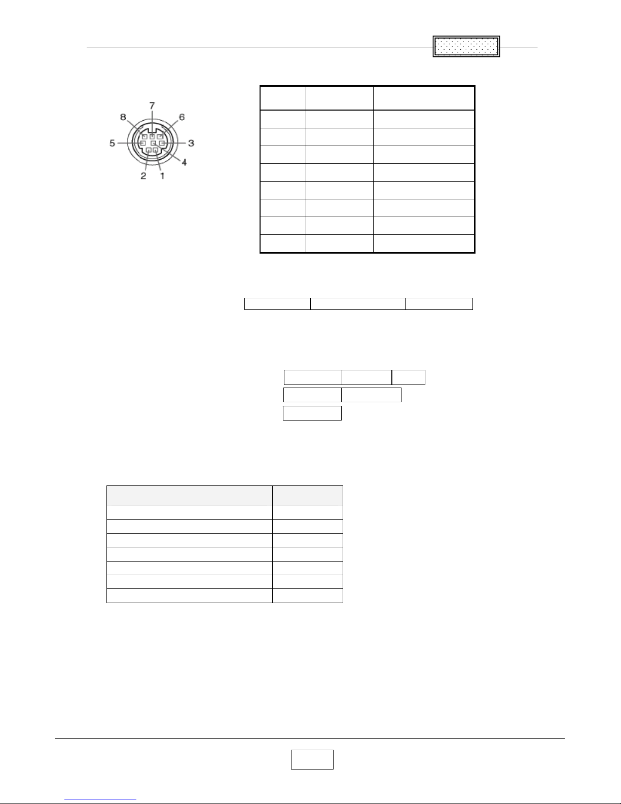
■ CONTROL terminal
● Pin assignment
Mini DIN 8 Pin Connector
●
lnterface format
1 Communication method
RS-232C,9600bps,No Parity,Data Length: 8 bits;
Stop Bit Length: 1 bit
2 Communication format
Only 1 command valid per communication.
3 Data format For input commands,only ASCll-compliant all-uppercase alphanumeric
characters supported.
4 Replies Acknowledge :Normally ended
:Aborted
No Acknowledge
If commands are to be sent consecutively, wait for the response from the projector
before sending the next command.
● Main Commands
Item Command
Power on PON
Power off PDF
Icon display on MC0
Icon display off MO1
Auto setting (RGB input) PAT
Status display on DON
Status display off DOF
Note
● Contact your dealer for control cable and other commands.
Pin
No.
Signal
Name
Description
1 RXD Receiving data
2 CTS Consent to send
3 DSR Data set ready
4 GND Signal ground
5 RTS Request to send
6 N.C No connection
7 TXD Sending data
8 GND Signal ground
STX(02h) Command(3Byte) ETX(03h)
ACK(06h) CR (0Dh) Data
ACK (06h)
ESC (1Bh)
NAK (15h)
Chapter 1
1-3
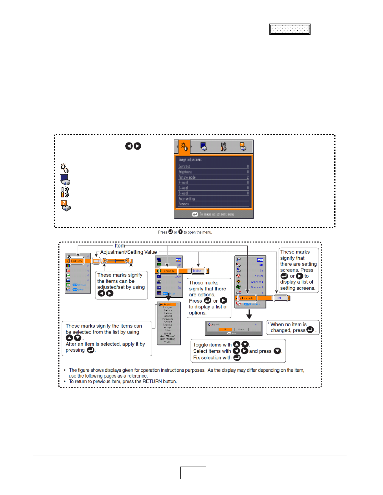
Using the Menus
You can call up on-screen menus, and conduct a number of adjustments and settings using the operation
buttons on the control panel (main unit side) and remote control.
■ How to use the menus
The menu shown below is for operation instructions purposes and might differ from the actual display.
1. Press the MENU button Display the Setting display menu
2. Select a Category
3.Adjustments & Settings
4.End Press the MENU button.
(The menu disappears 30 seconds after the last operation.)
Select a Category by using
There are following four Categories:
Image adjustment menu
Display Setting menu
Default Setting menu
Status Display menu
Displays the current
adjustments and Settings
of selected Category.
Item shown with gray
cannot be adjusted with
the current input source
1-4
Chapter 1
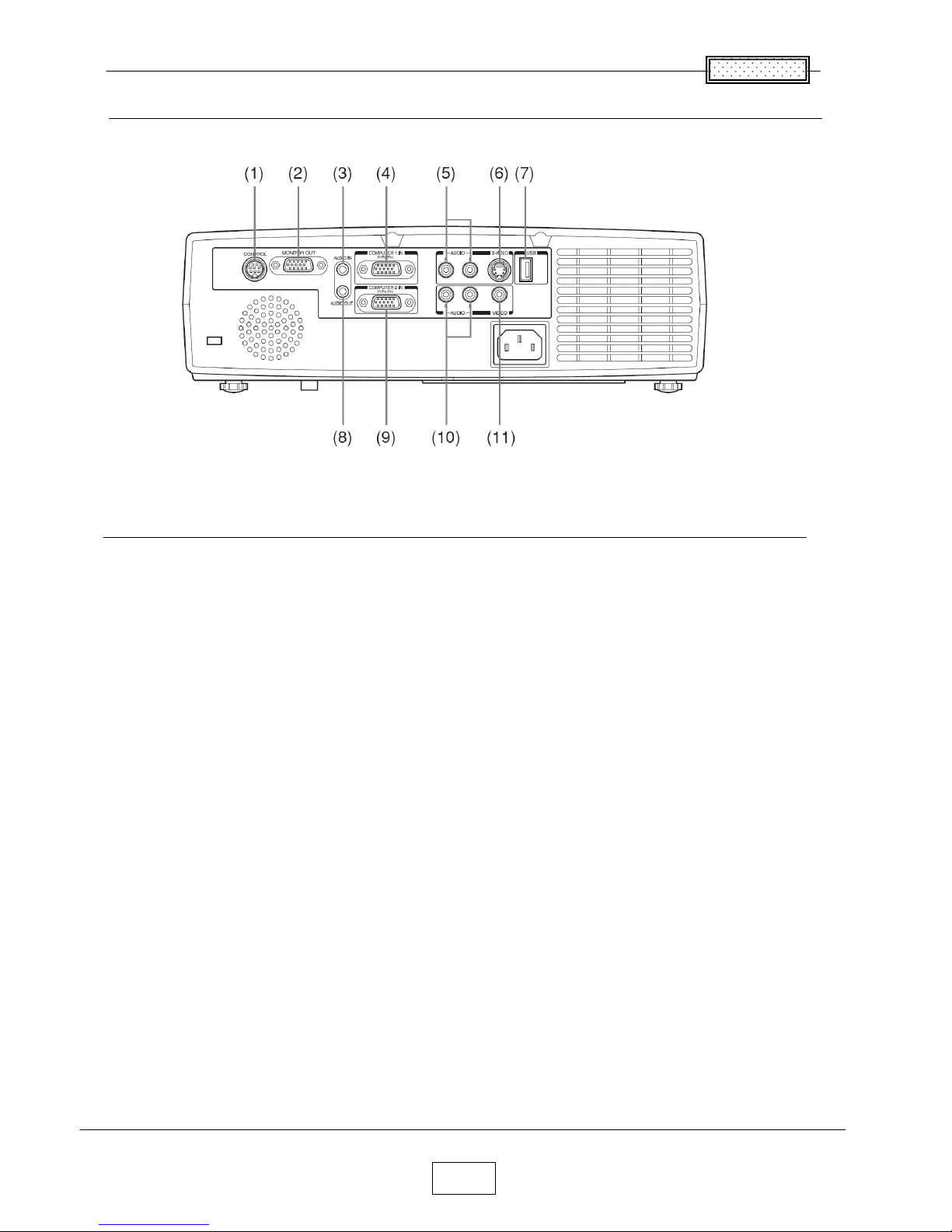
Names of the Terminals on the Rear Panel
Name :Main Function
(1) CONTROL terminal : When operating the projector via a computer, connect
this to the controlling computer’s RS-232C port.
(2) MONITOR terminal : Connect to a computer display, etc.
(3) AUDIO IN terminal : Input audio signals from a computer, or from video
equipment with a component video signal output terminal.
(4) COMPUTER 1 IN terminal : Input RGB signal from a computer or other source, or a
component video signal (Y/P
B/PR) from video
equipment.
(5) AUDIO (L/R) terminal : Input audio signals from video equipment.
(6) S-VIDEO terminal : Input S video signals from video equipment.
(7) USB terminal : Connects the supplied wireless LAN USB adapter or a
commercial USB memory.
(8) AUDIO OUT terminal : Outputs audio signals.
(9) COMPUTER 2 IN terminal : Input analog RGB signal from a computer or other
source,or a componet video signal (Y/P
B/PR) from
video equipment.
(10) AUDIO (L/R) terminal : Input audio signals from video equipment.
(11) VIDEO terminal Input video signals from video equipment.
1-5
Chapter 1
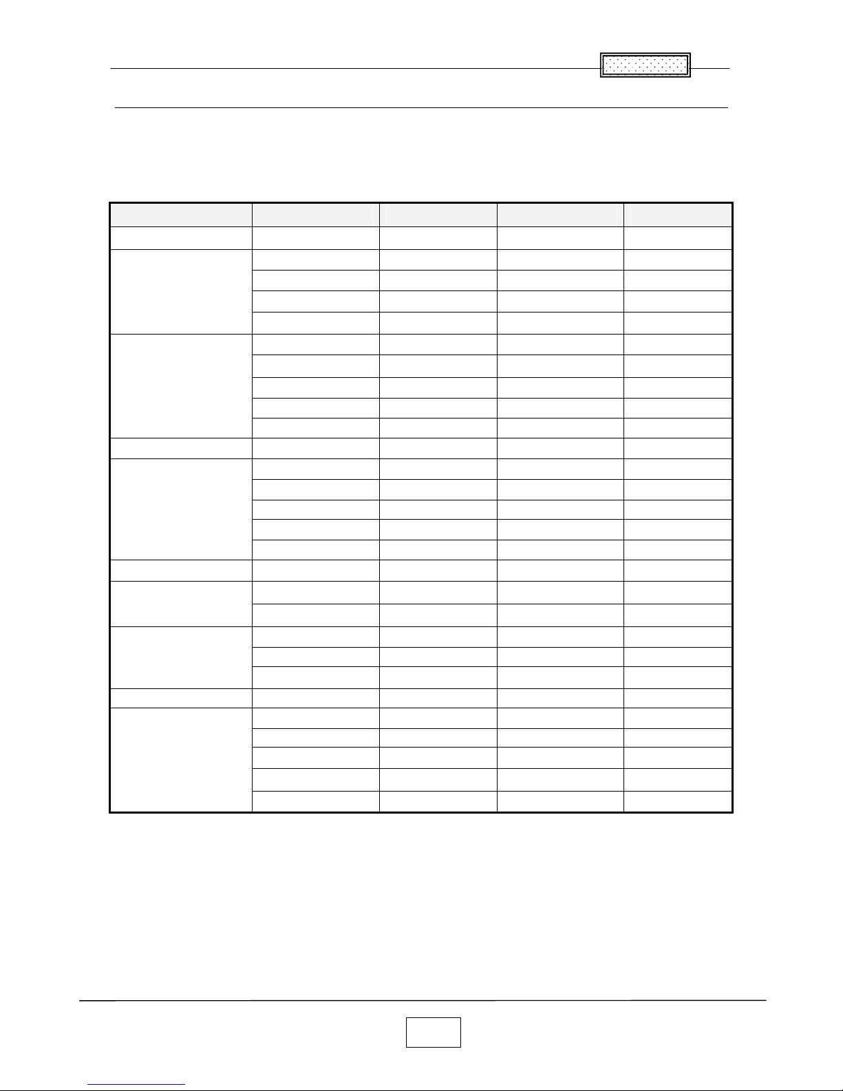
List of Supported Signals
■ List of Supported Signals(RGB signals)
This projector supports the following RGB signals. Note, however, that depending on the computer model,
the screen may show flicker or streaking. Please adjust the projector if this happens.
Resolution Mode Refresh Rate(Hz) H-frequency(kHz)
Clock(MHz)
720 x 400 720x400_85 85.039 37.927 35.500
VGA_60
59.940 31.469 25.175
VGA_72
72.809 37.861 31.500
VGA_75
75.000 37.500 31.500
640×480
VGA_85
85.008 43.269 36.000
SVGA_56
56.250 35.156 36.000
SVGA_60 60.317 37.879 40.000
SVGA_72 72.188 48.077 50.000
SVGA_75 75.000 46.875 49.500
800 x 600
SVGA_85 85.061 53.674 56.250
832 x 624
MAC16" 74.550 49.725 57.283
XGA_60 60.004 48.363 65.000
XGA_70 70.069 56.476 75.000
XGA_75 75.029 60.023 78.750
XGA_85 84.997 68.667 94.500
1024 x 768
MAC19" 74.700 60.134 79.857
1152 x 864
SXGA1_75 75.000 67.500 108.000
QuadVGA_60 60.000 60.000 108.000
1280 x 960
QuadVGA_85 85.002 85.938 148.500
SXGA3_60
60.020 63.981 108.000
SXGA3_75 75.025 79.976 135.000
1280 x 1024
SXGA3_85 85.024 91.146 157.500
1400 x 1050 SXGA+ 59.978 65.317 121.750
UXGA_60 60.000 75.000 162.000
UXGA_65 65.000 81.250 175.500
UXGA_70 70.000 87.500 189.000
UXGA_75 75.000 93.750 202.500
1600 x 1200
UXGA_85 85.000 106.250 229.500
Note
● Signals whose resolution exceeds the native resolution (1024×768 pixels) will be
compressed. For this reason, some information may be lost, or image quality may be affected.
Chapter 1
1-6
■ List of supported signals (Y/PB/PR signals)
■ List of supported signals (Video, S-Video signals)
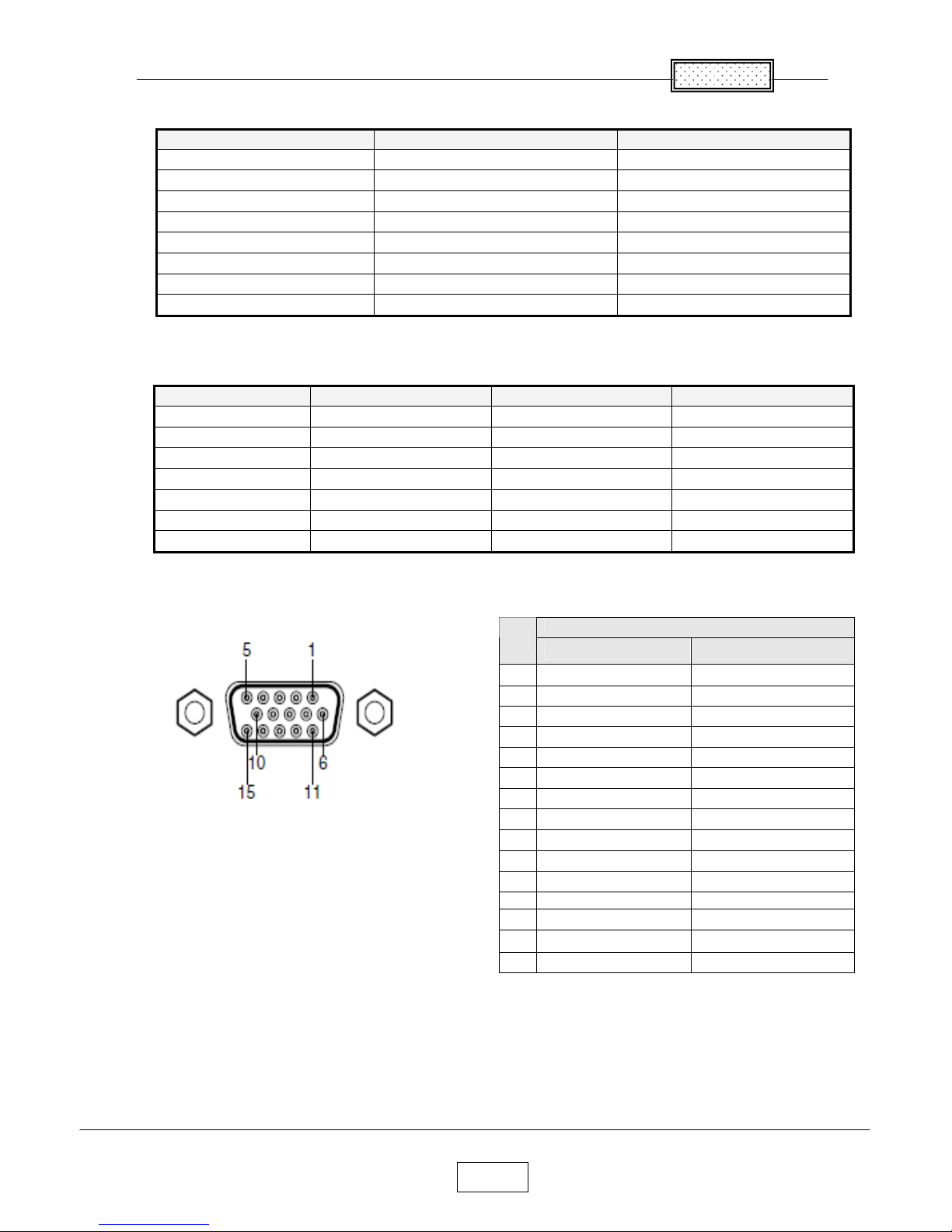
■ Pin assignment of COMPUTER 1 IN, COMPUTER 2 IN &MONITOR terminals
Mini D sub 15 Pin connector
• RGB input
RGB signals :0.7V (p-p) 75 Ω
Horizontal sync signal :TTL level (Pos/neg polarity)
Vertical sync signal :TTL level (Pos/neg polarity)
• Y/PB/PR input
Y signal :1.0V (p-p) 75 Ω
PB/PR signals :0.7V (p-p) 75 Ω
*Do not connect anything
Signal format fh(kHz) fv(Hz)
480i(525i)@60Hz 15.73 59.94
480p(525p)@60Hz 31.47 59.94
576i(625i)@50Hz 15.63 50.00
576p(625p)@50Hz 31.25 50.00
720p(750p)@60Hz 45.00 60.00
720p(750p)@50Hz 37.50 50.00
1080i(1125i)@60Hz 33.75 60.00
1080i(1125i)@50Hz 28.13 50.00
Video mode fh(kHz) fv(Hz) fsc(MHz)
NTSC 15.73 60 3.58
PAL 15.63 50 4.43
SECAM 15.63 50 4.25 or 4.41
PAL-M 15.73 60 3.58
PAL-N 15.63 50 3.58
PAL-60 15.73 60 4.43
NTSC4.43 15.73 60 4.43
Pin description
Pin
No.
During RGB input During Y/PB/PR input
1 Video signal (R) Color difference signal (PR)
2 Video signal (G) Luminance signal (Y)
3 Video signal (B) Color difference signal (PB)
4 GND *
5 GND *
6 GND (R) GND (PR)
7 GND (G) GND (Y)
8 GND (B) GND (PB)
9 N.C GND
10 GND *
11 GND *
12 N.C *
13 Horizontal sync signal *
14 Vertical sync signal *
15 N.C *
2-1
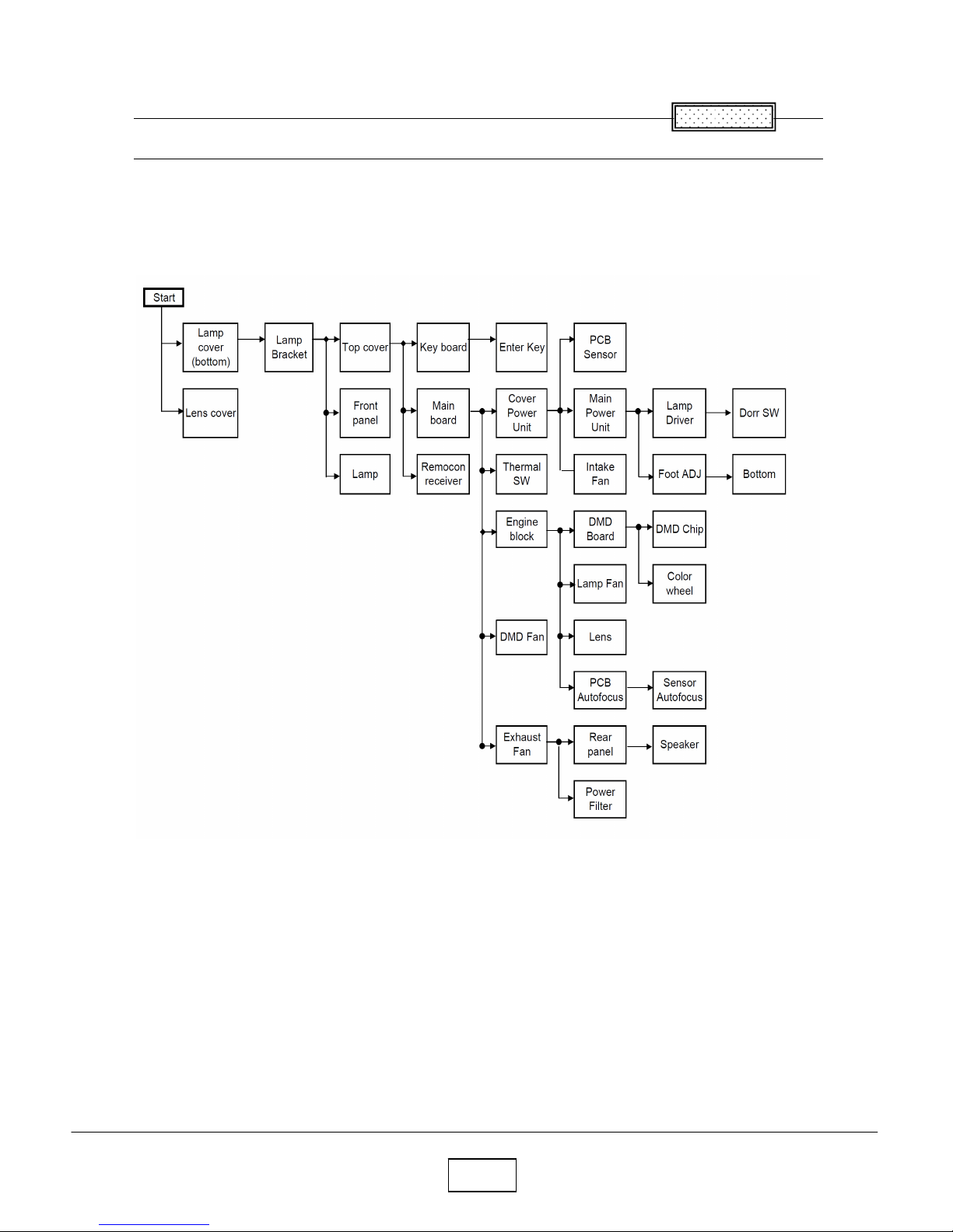
Chapter 2
Replaceable Part Hierarchy
The flow chart below shows what parts must be removed to access each replaceable part in the projector.
The parts on the first level (Ex. Lamp cover) are accessible without removing any other parts.
The move levels down that a part is, the more parts you need to remove in order to access it.
Chapter 2
Chapter 2
2-2
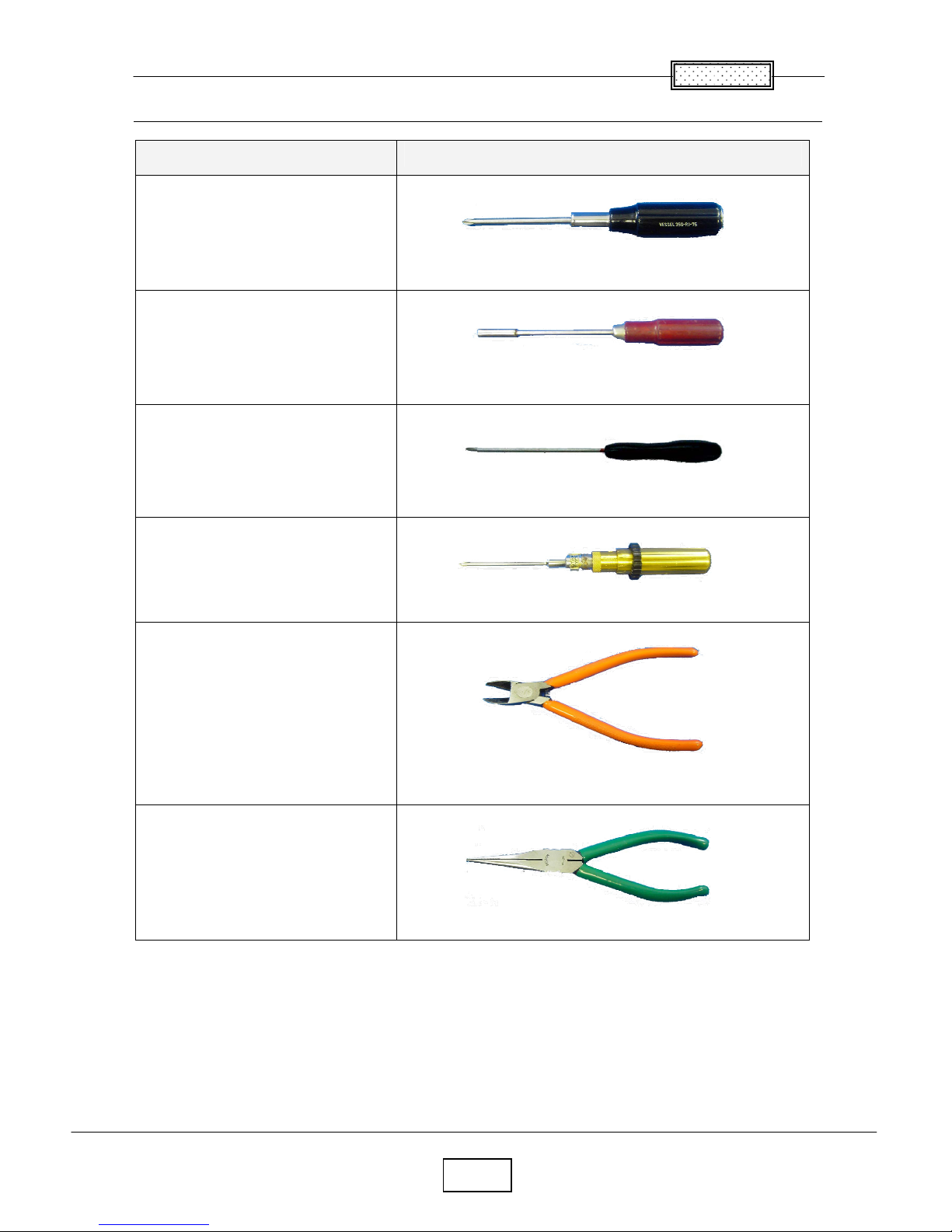
Required Tools
Item Photo
Driver bit (+) No 2
Box driver M3
Driver bit (+) No 0
Torque driver bit (+) No 1
Nippers
Cutting pliers
Chapter 2
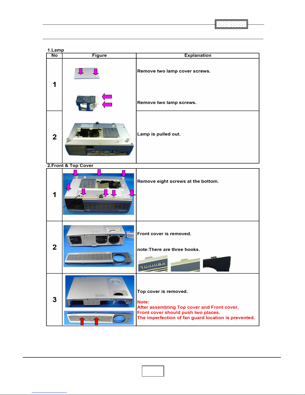
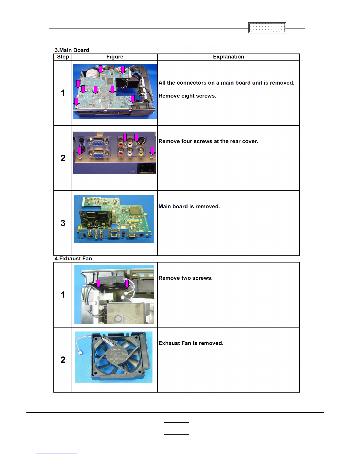
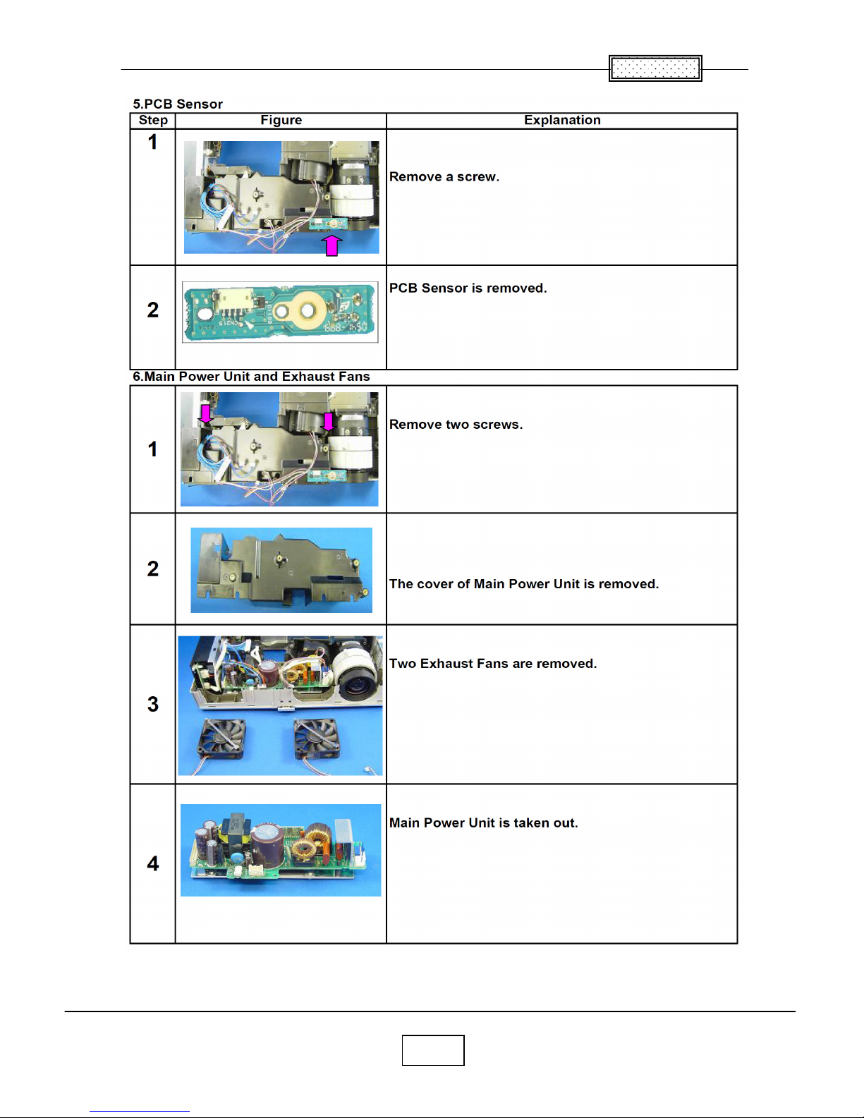
2-3
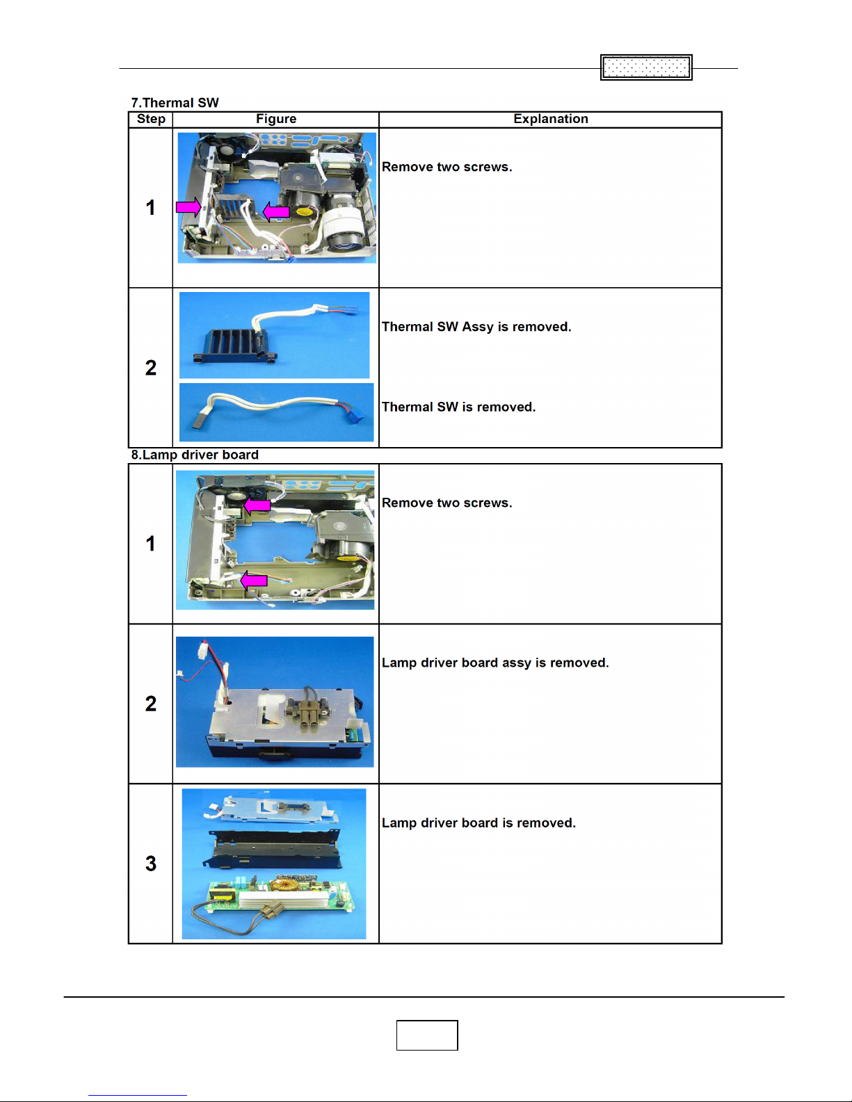
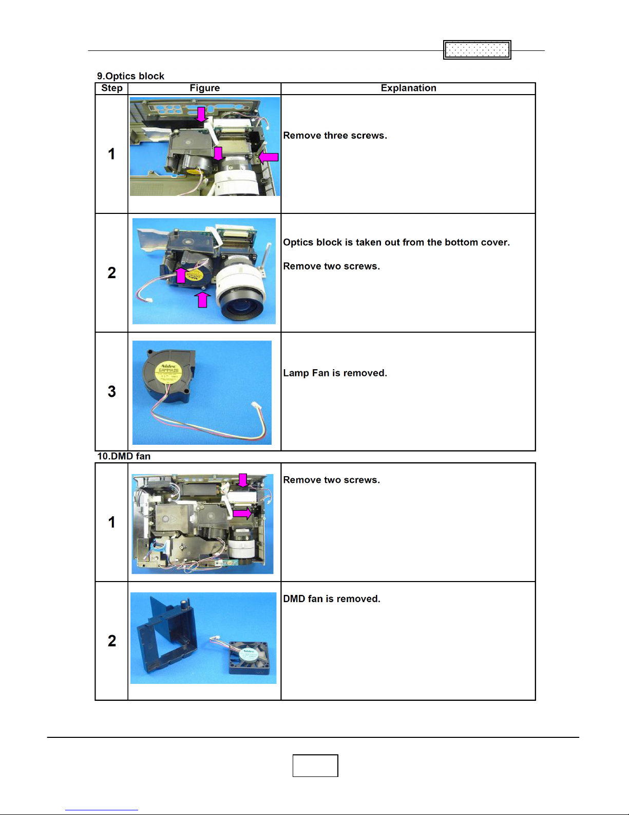
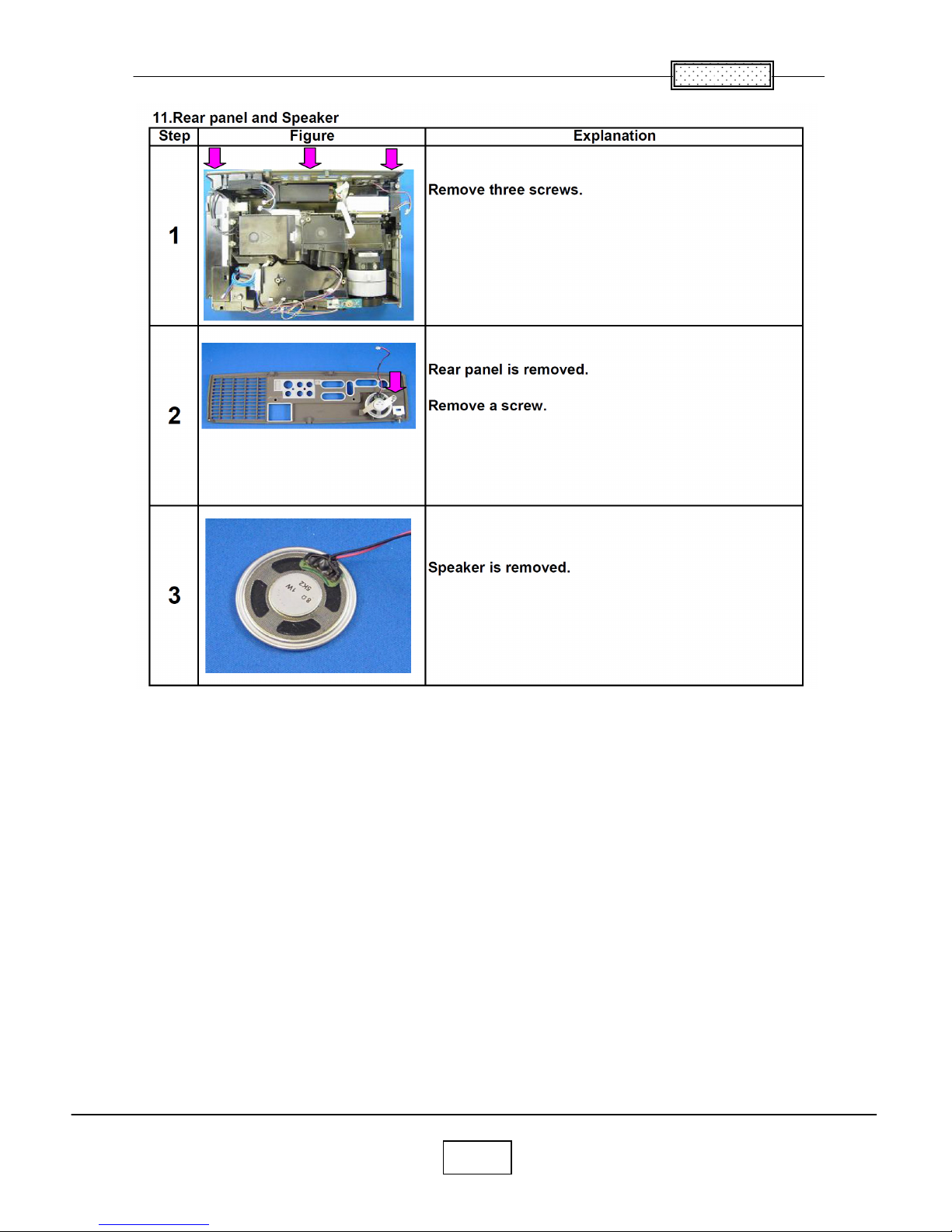
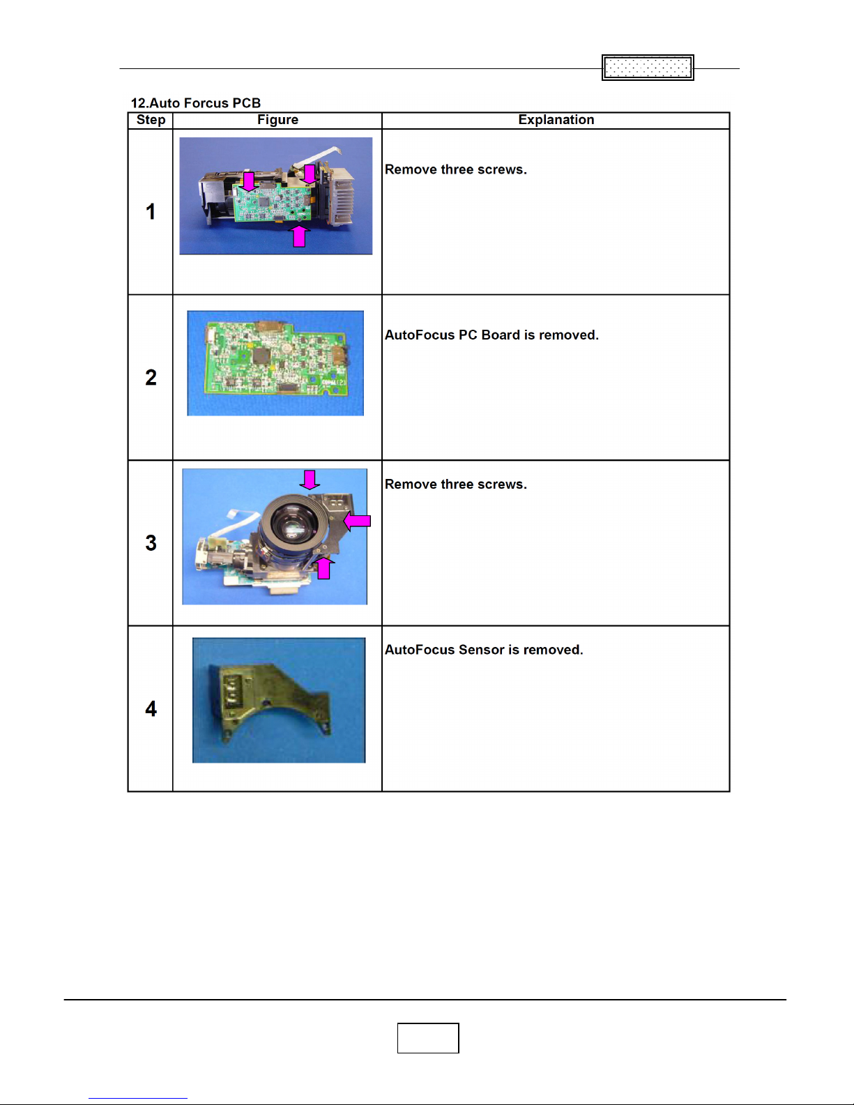
Parts Replacement
Chapter 2
2-4
Chapter 2
2-5
Chapter 2
2-6
Chapter 2
2-7
Chapter 2
2-8
Chapter 2
2-9
3-1
Chapter 3
SINGOWS 2000
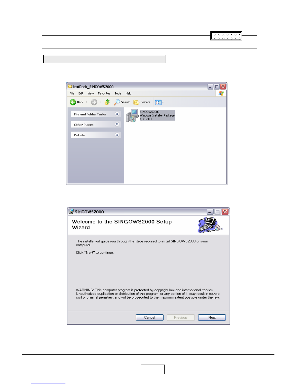
The software you download is bundled into one .MSI file.
Double-click the file to install the signal generating software.
The Install Wizard appears,ready to begin the install process.
Click the next button.
C
hapter 3
Install the Software on the Computer
Chapter 3
3-2
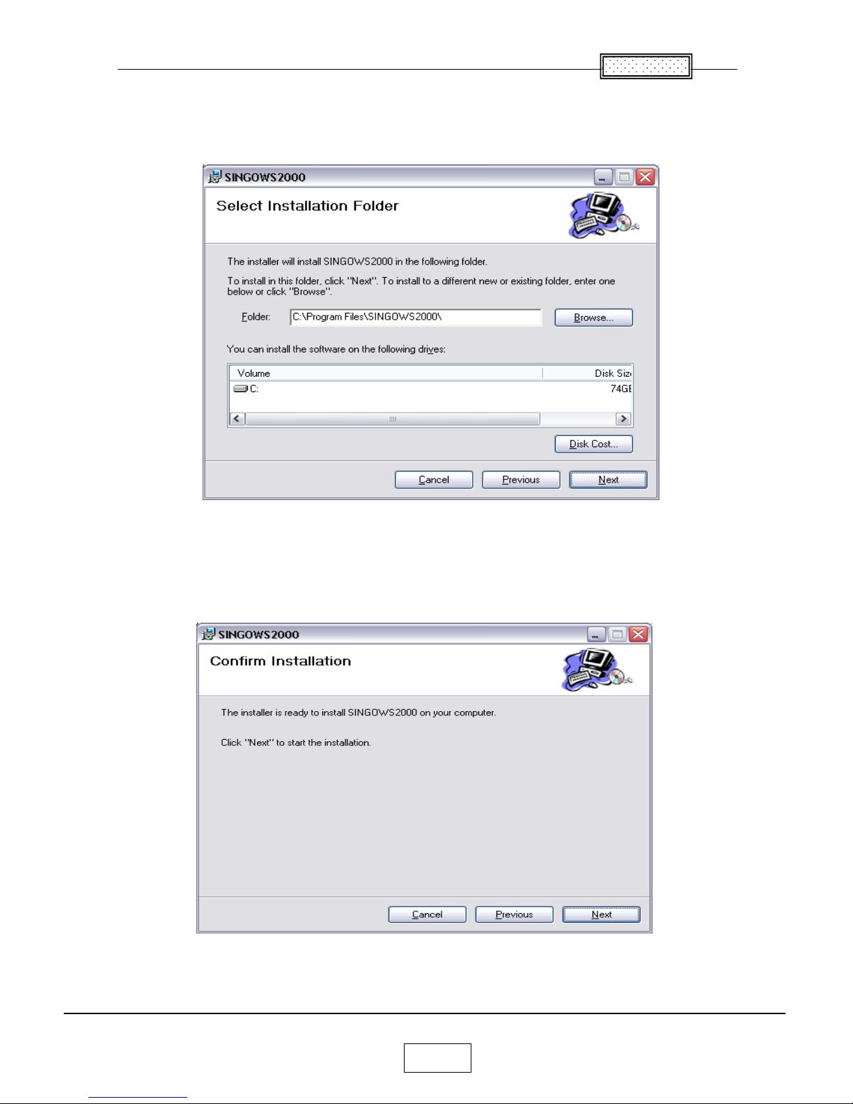
The Select Installation Folder dialog box appears.
Navigate to the location where you stored the software files.
Click the next button.
The confirm Installation dialog box appears.
Click the next button.
Chapter 3
3-3
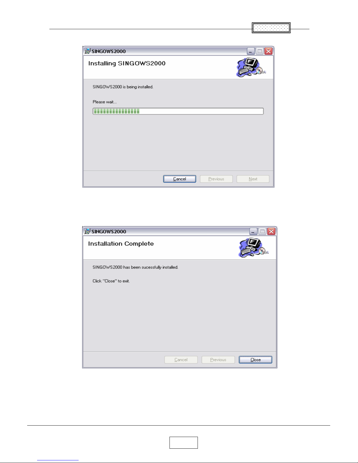
The Installing software dialog box appears.
The Installation Complete dialog box appears.
Click the close button.
Chapter 3
3-4
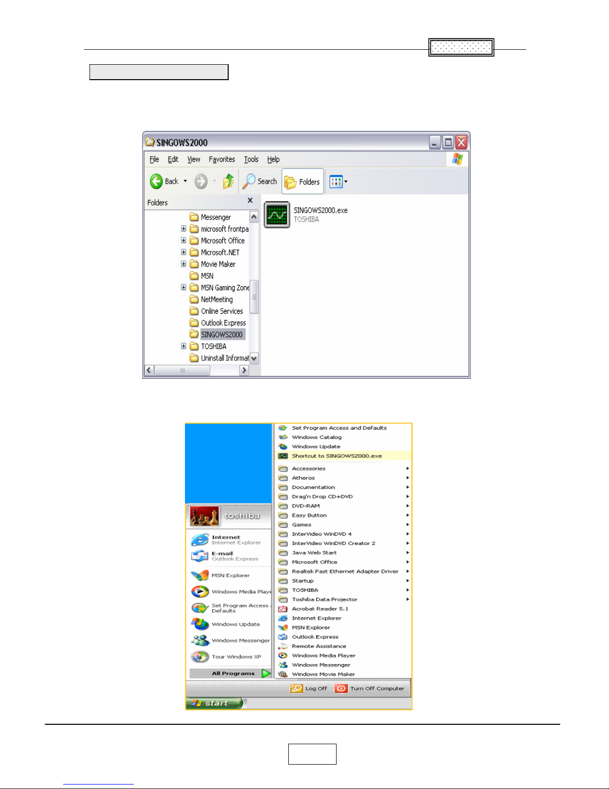
Open Windows Exploler, navigate to the location where you stored the files, Then double click the
SINGOWS2000.EXE.
Moreover, even if it chooses the shortcut of the All programs of start, it can startup.
Startup the Software
4-1
Chapter 4
Firmware Upgrade
Connect the control cable to the control terminal on the projector.
Then plug the RS232C connector on the other end of the cable into a RS232C port on the computer.
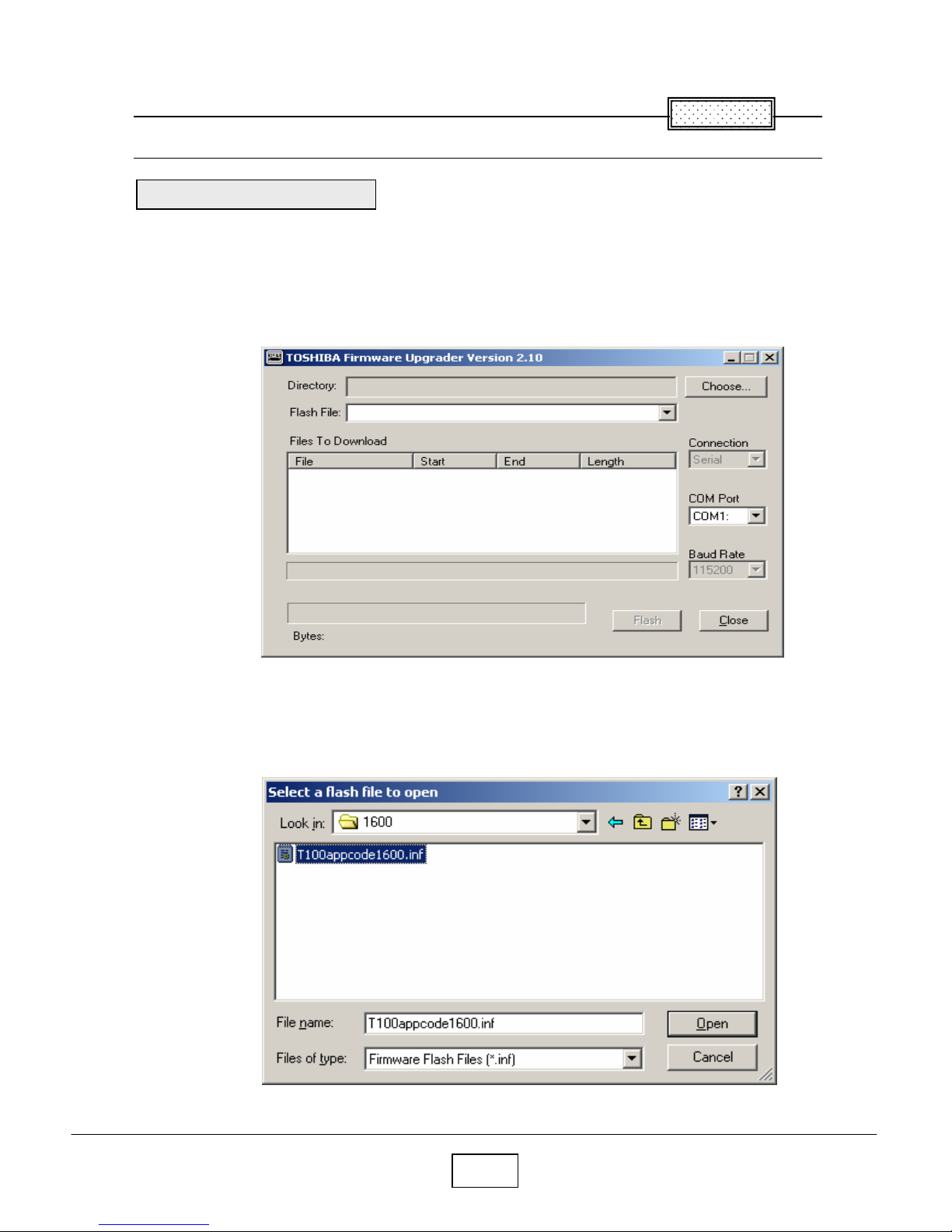
Open Windows Explorer navigate to the location where you stored the upgrade files, and then double click
the Firmware Upgrader.exe.
The Upgrade Wizard appears. Click the Choose button to open the Select File Dialog box.
In the Open File dialog box, select the .inf file, and then click Open button.
Upgrade the software
Chapter 4
Chapter 4
4-2
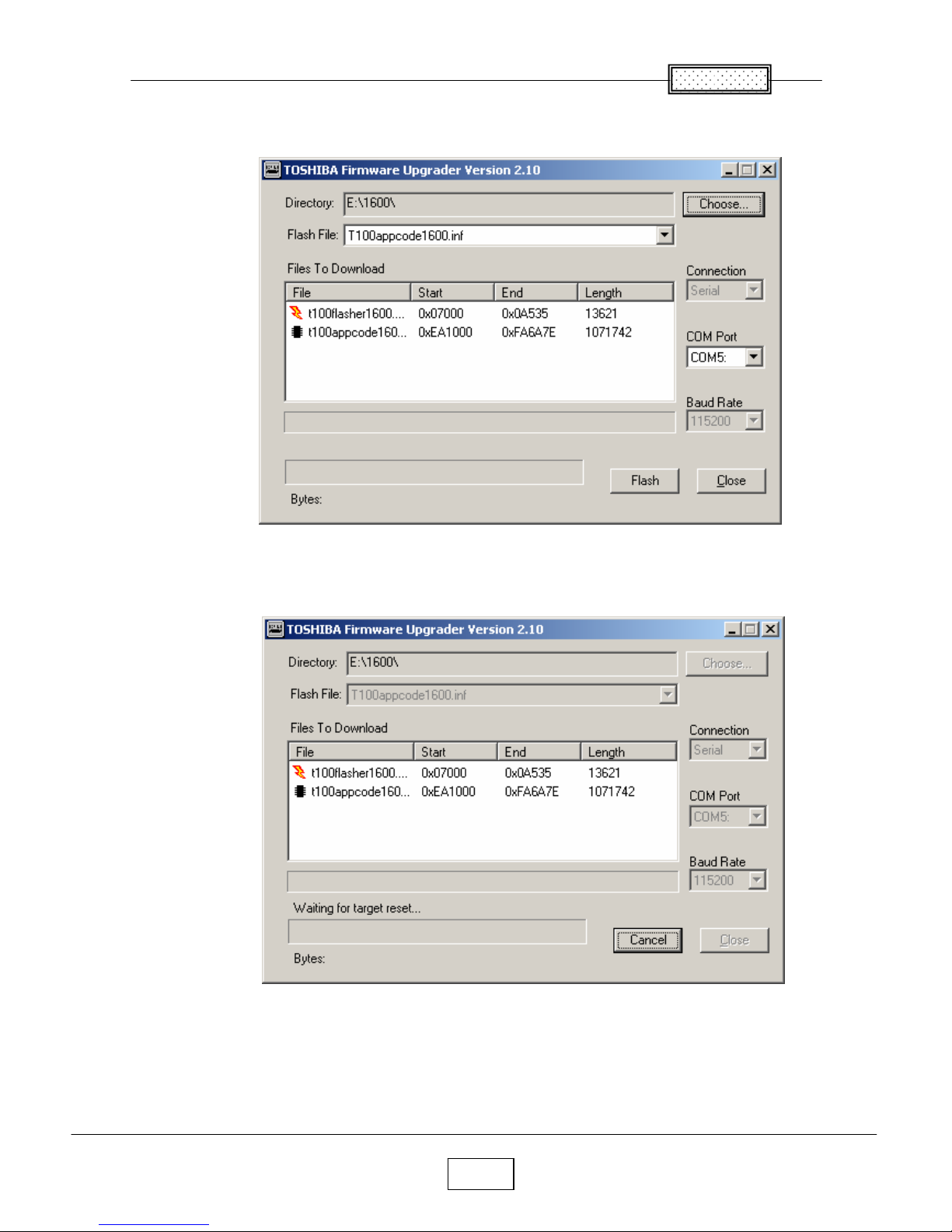
The upgrade file appears in the Select File box.
Select the COM port.
Click Flash button.
Chapter 4
4-3
Press and hold the projector’s [Input] and [Keystone] keys, and then plug in the power cord.
The projector starts the Firmware upgrade, [LAMP], [TEMP] and [FAN] LED’s are Green blinking after
Orange blinking.
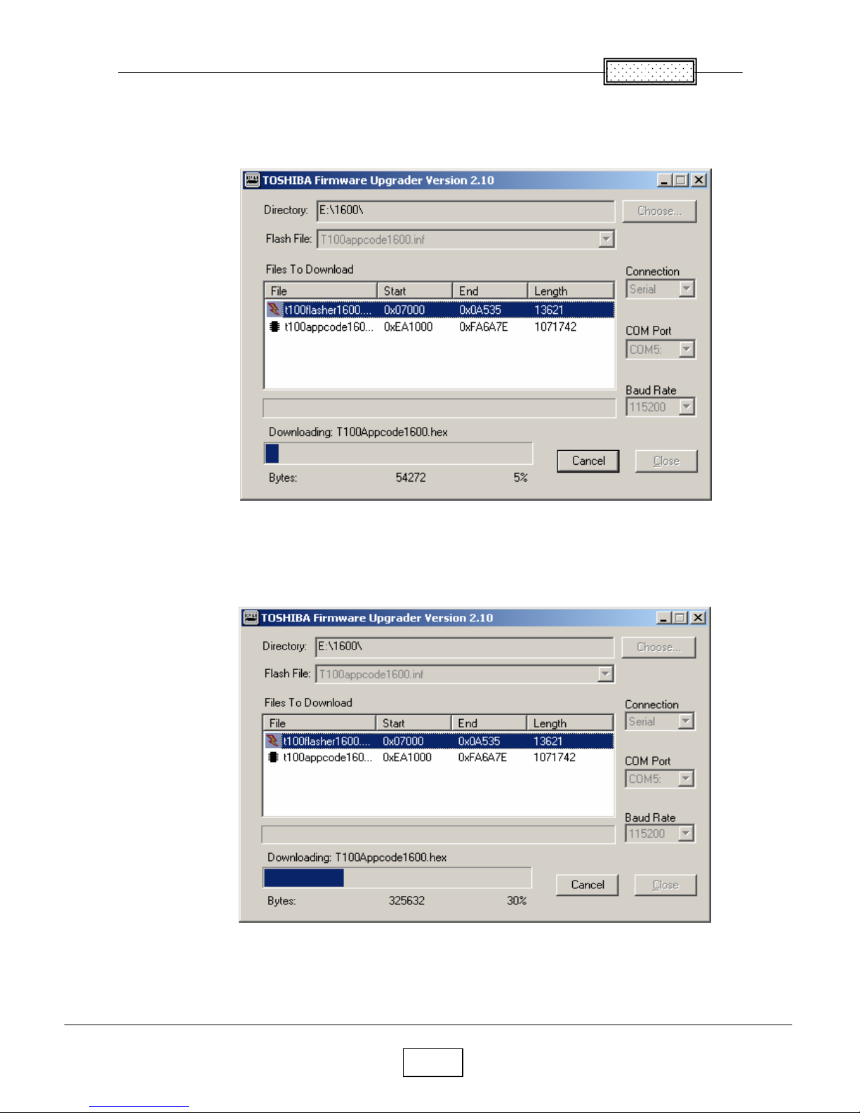
The computer begins downloading the upgrade files to the projector.
The process may take several minutes.
Chapter 4
4-4
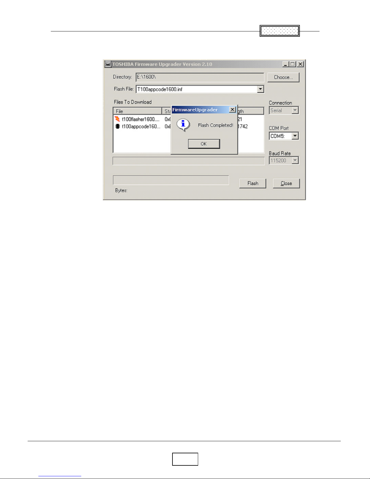
When the upgrade finishes normally, the following dialog box appears.
Click the Close button.
The upgrade is complete.
Chapter 4
4-5
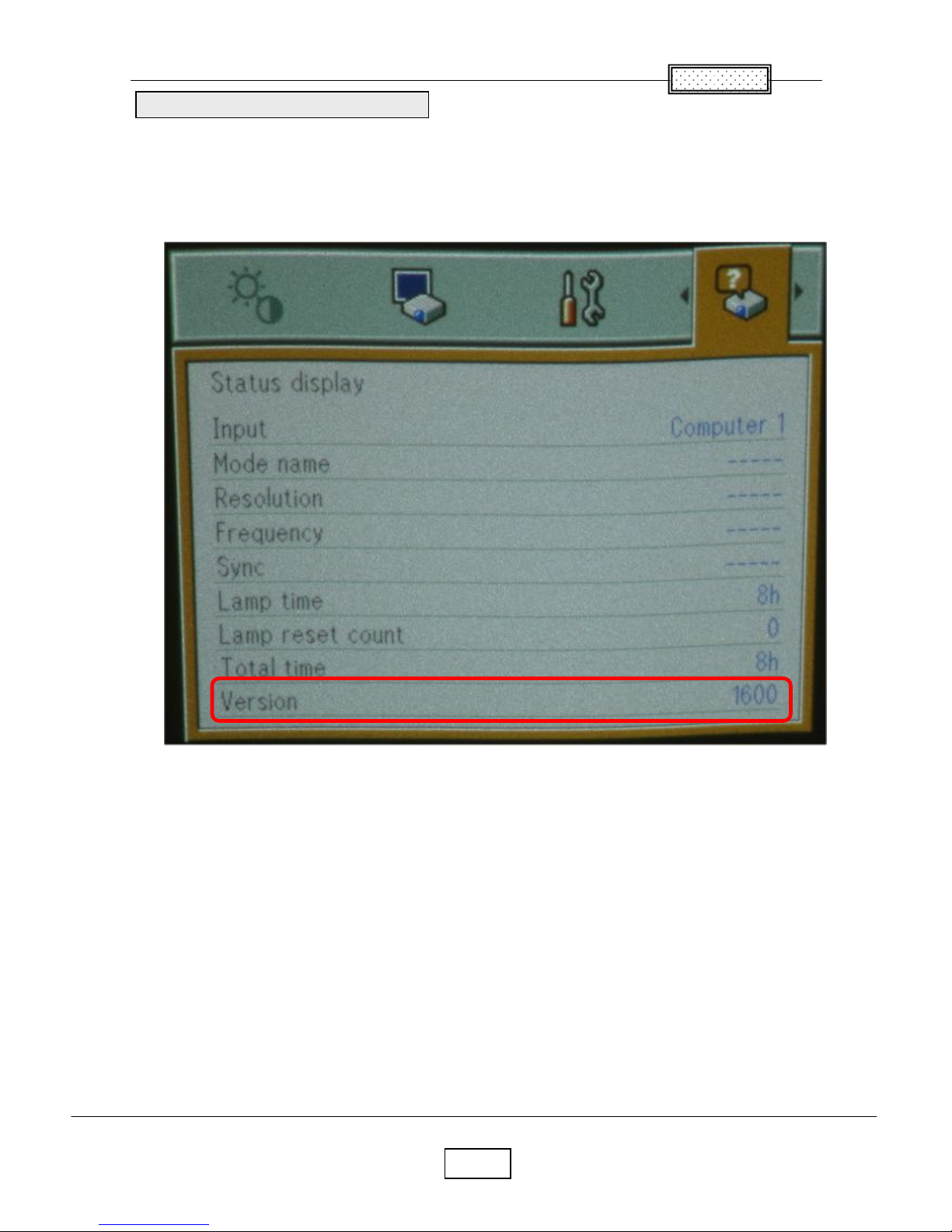
1. Power up the projector.
2. On the projector keypad, press the MENU key to display the menus.
3. Press button Right or Left arrow to highlight Setting display.
4. The Setting display dialog box display the software version.
These should match the upgrade version you downloaded.
Confirm the software upgrade
 Loading...