

Toshiba TDP-T8, TDP-T9, TDP-S8 Service Manual
SERVICE MANUAL
FILE NO. 330-200601GR
DLP DATA PROJECTOR
TDP-T9
The above models are classified as green product (s) (*1), as indicated by the underlined serial number (s).
This Service Manual describes replacement parts for green product (s). When repairing any green product (s), use
the parts described in this manual and lead-free solder (*2).
For (*1) and (*2) , see the next page.
Published in Japan, January 2006 GREEN© TOSHIBA CORPORATION
TDP-S8
TDP-T8
(*1) GREEN PRODUCT PROCUREMENT
The EC is actively promoting the WEEE & RoHS Directives that define standards for recycling
and reuse of Waste Electrical and Electronic Equipment and for the Restriction of the use of
certain Hazardous Substances. From July 1, 2006, the RoHS Directive will prohibit any
marketing of new products containing the restricted substances.
Increasing attention is given to issues related to the global environmental. Toshiba Corporation
recognizes environmental protection as a key management tasks, and is doing its utmost to
enhance and improve the quality and scope of its environmental activities. In line with this,
Toshiba proactively promotes Green Procurement, and seeks to purchase and use products,
parts and materials that have low environmental impacts.
Green procurement of parts is not only confined to manufacture. The same green parts used in
manufacture must also be used as replacement parts.
(*2) LEAD-FREE SOLDER
This product is manufactured using lead-free solder as a part of a movement within the consumer
products industry at large to be environmentally responsible. Lead-free solder must be used in
the servicing and repair of this product.
WARNING
This product is manufactured using lead free solder .
DO NOT USE LEAD BASED SOLDER TO REPAIR THIS PRODUCT !
The melting temperature of lead-free solder is higher than that of leaded solder by 86°F to 104°F
(30°C to 40°C). Use of a soldering iron designed for lead-based solders to repair product made
with lead-free solder may result in damage to the component and or PCB being soldered. Great
care should be made to ensure high-quality soldering when servicing this product especially
when soldering large components, through-hole pins, and on PCBs as the level of heat
required to melt lead-free solder is high.

S8 T8 T9
Preface
This manual is applied to S8 T8 T9 0.55” DMD SVGA (S8) and XGA (T8/T9) digital projection
system. It’s the mode of single Panel, 180 Watt Compact P-VIP Lamp and 800(H) x 600(V)
(S8) and 1024(H) x 768(V) (T8/T9) and resolution. The manual gives you a brief description
of basic technical information to help in service and maintaining the product.
Your customers will appreciate the quick response time when you immediately identify problems that occur with our products. We expect your customers will appreciate the service that
you offer them.
This manual is for technicians and people who have an electronic background. Send the
product back to the distributor for repairing and do not attempt to do anything that is complex
or is not mentioned in the troubleshooting.
NOTICE :
The information found in this manual is subject to change without prior notice. Any subsequent
changes made to the data herein will be incorporated in further edition.
Copyright 2005, December
All Rights Reserved
Manual Version 1.0

Table of Contents
C h ap t e r 1 I nt r o du c t io n 1 - 1
Highlight 1-1
Mechanical Specifications 1-2
Electrical Specifications 1-3
Optical Specifications 1-4
Environmental 1-5
Compatible Mode 1-6
Chapter 2 Disassembly Process 2-1
Equi pment Needed 2-1
Disassemble Lamp, Keypad Board, Top Cover and Front Cover 2-2
Disassemble IR Sensor Board, Main Board, I/O Module, Speaker,
Back Cover and Lamp Driver 2-5
Disassemble Lamp Driver Module, LVPS, Thermal Sensor,
Fan Module, Photo Sensor and Color Wheel 2-9
Disassemble DMD Board, DMD Chip, Thermal Switch, Focus Ring,
Zoom Ring, Engine Module, Blower Fan and Elevator 2-13
Chapter 3 Troubleshooti ng 3-1
Equi pment Needed 3-1
Adjustment Needed 3-1
LED Lighting Message 3-1
Main Procedure 3-2
Chapter 4 Function Test and Alignment Procedure 4-1
Test Equipment 4-1
Test Condition 4-1
Test Display Modes & Pattern 4-2
Inspection Procedure 4-5
Guide to Entering Factory Mode and Reset in OSD 4-7
C h ap t e r 5 F i r m w a r e U p g r a d e P r o c e d u r e 5 - 1
Equipment Needed 5-1
Installation Procedure 5-2
Firmware Upgrade Procedure 5-4
S8 T8 T
Chapter 6 Appendix A 6-1. 6-2
Chapter 7 Spare part 7-1. 7-2. 7-3
1-1
S8 T8 T9
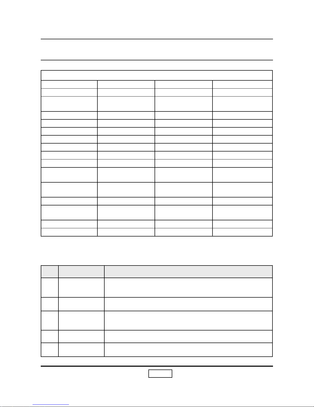
No Item Description
1 DMD
One panel 0.55” DMD SVGA projection system (S8)
One panel 0.55” DMD XGA projection system (T8 / T9)
2 Lamp 200W Lamp dimmable to 180W
3
Cooling
System
High efficiency cooling system with low system acoustic noise
level
4 Weight Light weight < 4.5 lbs
5 Zoom lens Manual focus projection 1:1.10 zoom lens
Chapter 1
Introduction
1-1 Highlight
T9/T8/S8 main different parts
Parts \ Model T9 T8 S8
MAIN BOARD T9 F/W Same as T9 S8 F/W
DMD Chip 0.55 XGA 0.55 XGA(Same as
T9)
0.55SVGA
Top Cover T9 T8 S8
Bottom Cover T9 Same as T9 S8
Front Cover T9 T8 Same as T9
Rear Cover T9 Same as T9 S8
Lamp Cover T9 Same as T9 S8
KEYPAD CAP T9 Same as T9 S8
ELEVATOR BASE T9 Same as T9 S8
ELEVATOR PUSH
BUTTON
T9 Same as T9 S8
Remove Controller Interlink (with
mouse)
SMK(Same as S8) SMK
User’s Manual (CD) T9 T8 S8
User’s Manual (Pa-
per)
T9 T8 S8
Spec label T9 T8 S8
Battery T9 #4 Same as S8 S8 #3
1-2
S8 T8 T9
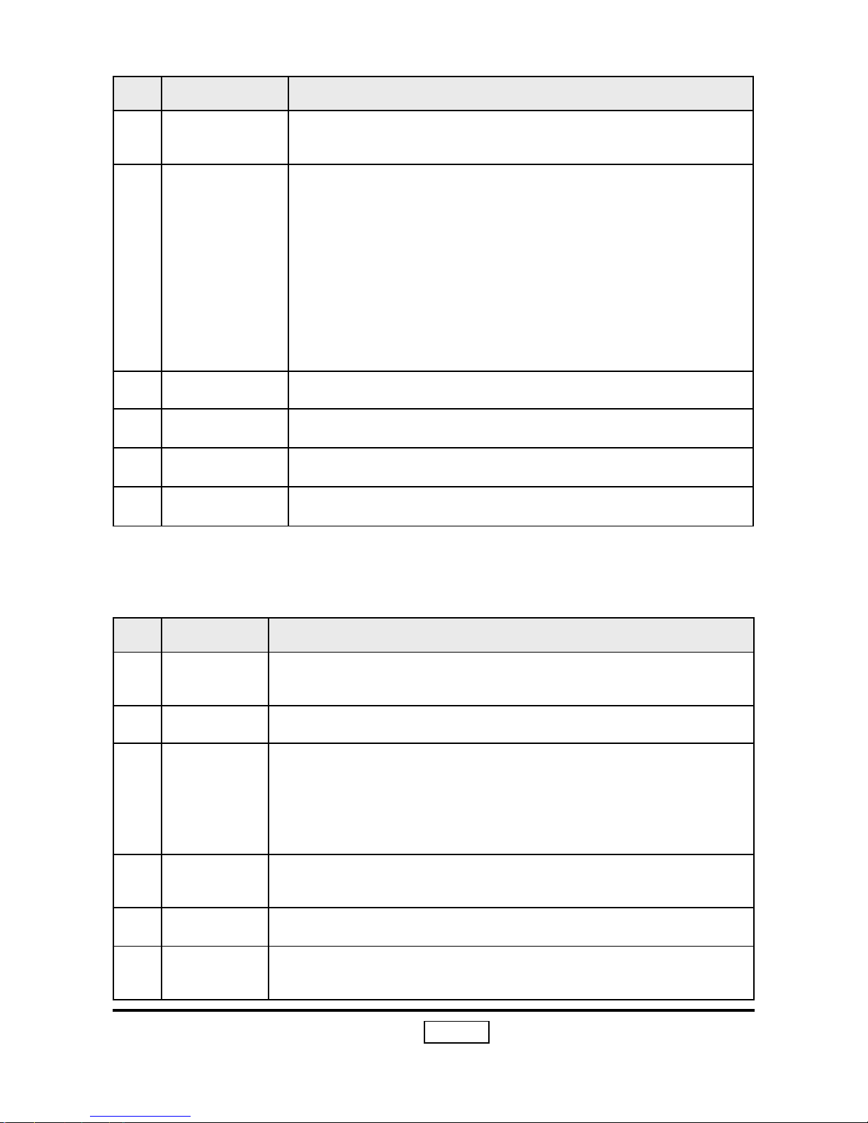
No Item Description
1
Dimensions
(WxHxD)
239*107*207 mm
2 Weight < 4.5 lbs.
3
Cooling
System
-Advanced air flow
-Two fans with low system acoustic noise level
-Temperature control circuits with adaptive voltage control fan
speed
-Maximum touch temperature follows UL60950
4 Cabinet
Provides space for PCB boards, fan, optical engine, power supply Lamp
5 Tilt Angle 6 degree with elevator mechanism
6
Keystone
correction
+/ -15 degree
1-2 Mechanical Specifications
No Item Description
6 Resolution
True 800X600 resolution, 16.7M True colors (S8)
True 1024 X 768 resolution, 16.7M True colors (T8/T9)
7
Video capability
-With up, down, left, and right screen reverse
-Build-in full screen NTSC/PAL/SECAM video capability with
S-video / Composite / component through D-sub terminals
-SXGA/XGA/SVGA/VGA/MAC compatibility.
-Auto image re-sizing to 800x600 full screen (S8)
-Auto image re-sizing to 1024 x 768 full screen (T8/T9)
-Auto detection of computer signal input
-Auto Image synchronization (Auto-tracking /frequency /position adjustment)
-Powerful enlarge and freeze function
8 Expandiability Automatically saves adjustments for future use
9 Language On-screen menu with 14 languages
10 Voltage Adaptive voltage control fan speed
11 Speaker Built-in one speaker with 2 Watt amplifier
1-3
S8 T8 T9
No Item Description
1
Power
Supply
-Universal AC 100--240V~ 50 / 60 Hz with PFC input
-200W Lamp @ normal operation
-Variance FAN speed control ( Depend on temperature variance)
2
Power
Consumption
-250 Watt +/- 10% at normal operation
-Stand-by mode < 13W
3 Terminals
-One D-Sub 15-pin female connector for analog RGB / HDTV
component video
-One D-Sub 15-pin female connector for monitor output
-One 3.5 mm phone jack for audio input
-One 3.5 mm phone jack for audio output
-One Mini DIN 4-pin for S-Video Input
-One RCA Jack for Composite Video Input
-RS232 connector
4
Input signal
spec.
-PC Signal
-Hsync Frequency 31.35~80 kHz
-Vsync Frequency 56 ~ 85 Hz
-Video Signal RGB (PC)
-Analog RGB 0.7Vp-p, 75 ohm
-Analog RGB 1Vp-p, 75 ohm, Sync. signal
-Separate TTL H,V Sync.
-Composite TTL Sync.
-Video
-Composite video 1Vp-p,75 ohm
-S-video Luminance 75 ohm
-Chrominance 75 ohm
5
System Controller
TI DDP2000
6
Video Compatibility
Standards :
NTSC: M (3.58MHz), 4.43 MHz
PAL: B, D, G, H, I, M, N
SECAM: B, D, G, K, K1, L
HDTV: 480i/p, 576i/p, 720p, 1080i
1-3 Electrical Specifications
No Item Description
7
Lamp Door
Protection
Lamp power supply shut off automatically when door open
1-4
S8 T8 T9
No Item Description
1
Projection
lens
F# 2.7 – 3.0 @2.4m, f = 21.8 ~23.8mm @2.4m.
1.10X Manual Zoom Lens. (S8)
- F# 2.7 – 3.0 @2.4m, f = 21.81 ~ 23.77 mm @2.4m.
1.10X Manual Zoom Lens. (T8/T9)
2
Projection
Image Size
Adjustable from 34.67” to 254.22” (Diagonal)
3
Throw Distance
Suggested throw distance: 1.5~10m (Optical Performance)
4
Throw
Ratio
1.94 ~ 2.13; 100”/3.94m ~ 4.33m
5 Brightness
-1600 ANSI Lumens ( Typical ) (S8)
-1440 ANSI Lumens ( Minimum ) (S8)
- 1800 ANSI Lumens (Typical) (T8/T9)
- 1600 ANSI Lumens (Minimum) (T8/T9)
6 Contrast
-1800:1 Typical (Full on / full off)
-1200:1 Minimum (Full on / full off)
7 Uniformity
-60% Typical ANSI
-50% Minimum ANSI
8
TV Distortion
-Horizontal-Up: <= |+/-1%|
-Horizontal-Down: <= |+/-1%|
-Vertical: <= |+/-1%|
9 Lens Offset 115%+/-10%
10 Lamp Osram E17.5e 200W P-VIP Lamp
1-4 Optical Specifications
No Item Description
7
On-Screen
Display
Menu
14 languages selection:
English, François, German, Italiano, Espanol, Portuguese,
Russian, Swedish, Turkism, Polish, Japanese, Simplify Chinese, Traditional Chinese, Korea
1-5
S8 T8 T9
No Item Description
1
Temperature
- Operating: 5 - 35°C
- Storage: -20- - 60°C
If the lamp temp is too high, the warning message will appear.
2
Maximum
Humidity
- Operating: 5 - 35°C, 80% RH (Max.), non-condensing
- Storage: -20- - 60°C, 80%RH (Max.), non-condensing
3
Acoustic
noise level
- Normal mode: 38 dB(A)(typical at 23 +/-2 degree C)
- Dim mode: 35 dB(A) (typical at 23 +/-2 degree C)
- Noise measurement follows ISO 7779, A-weighted sound pressure level measurement, 7200 rpm color wheel rotational speed
4 Lamp life
3000 hours marketing at full power mode Up to 2000 hours
with 50% survival rate/ 50% maintenance to initial lumens at
full power mode (According to current lamp specification) 5000
hours marketing at eco-mode
Up to 3000 hours with 50% survival rate/ 50% maintenance to
initial lumens at eco-mode (According to current lamp specification)
5 Altitude
- Operating 0~2,500 ft, for 5°C~35°C
2,500~5,000 ft, for 5°C~30°C
5,000~10,000 ft, for 5°C~25°C
- Storage 40,000 ft
6 MTBF - Operating more than 12,000 hours ( 90% Confidence Level )
1-5 Environmental
1-6
S8 T8 T9
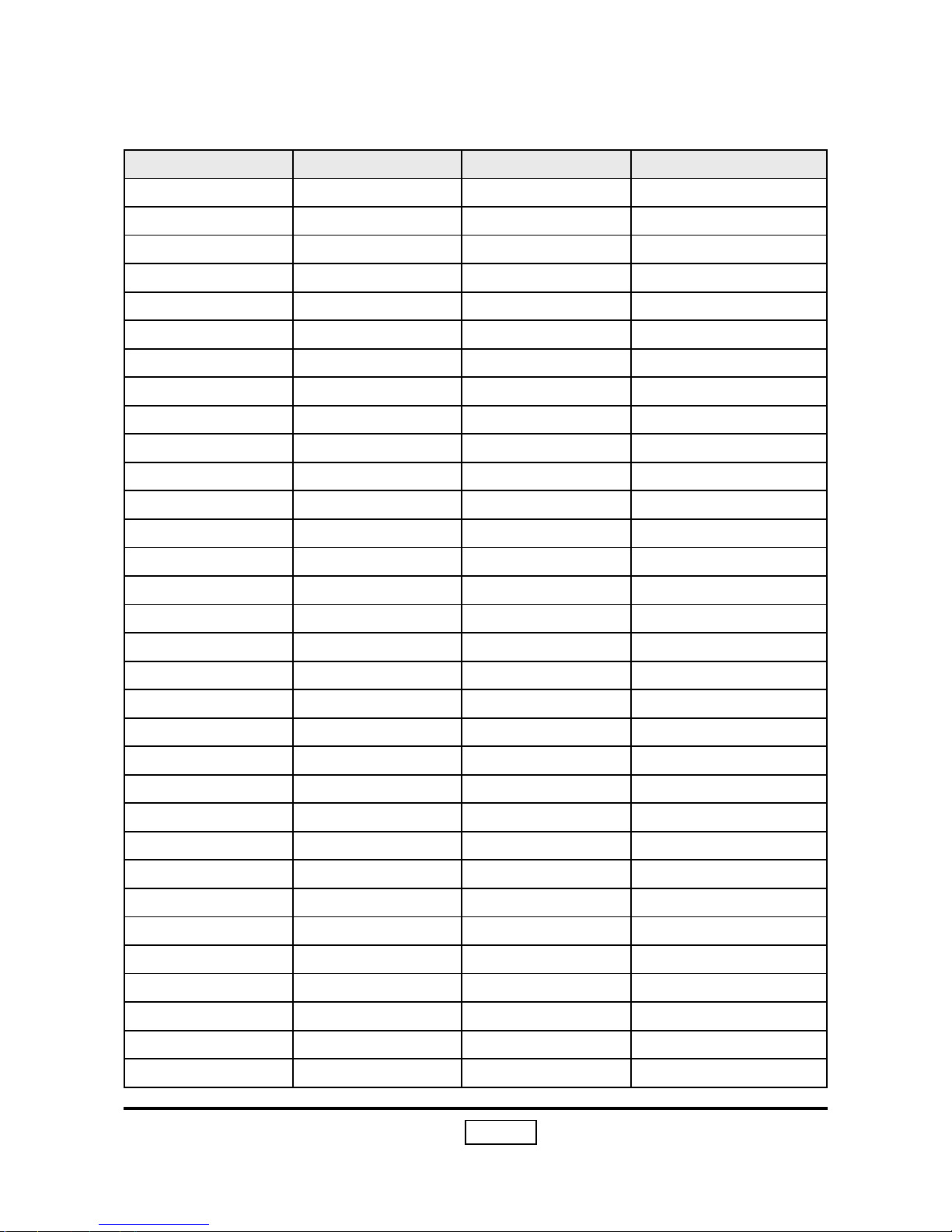
1-6 Compatible Mode
Compatibility Resolution V-Sync [Hz] H-Sync [KHz]
VGA 640x350 70 31.5
640x350 85 37.9
640x400 85 37.9
640x480 60 31.5
640x480 72 37.9
640x480 75 37.5
640x480 85 43.3
720x400 70 31.5
720x400 85 37.9
SVGA 800x600 56 35.2
800x600 60 37.9
800x600 72 48.1
800x600 75 46.9
800x600 85 53.7
XGA 1024x768 60 48.4
1024x768 70 56.5
1024x768 75 60.0
1024x768 85 68.7
SXGA 1152x864 70 63.8
1152x864 75 67.5
1152x864 85 77.1
1280x960 60 60
1280x960 75 75
1280x1024 60 63.98
1280x1024 75 79.98
MAC 16” 832x624 74.55 49.725
MAC 19” 1024x768 75 60.24
MAC 1152x870 75.06 68.68
MAC G4 640x480 60 31.35
i Mac DV 1024x768 75 60
i Mac DV 1152x870 75 68.49
i Mac DV 1280x960 75 75
Analog (S8/T8/T9)
2-1
S8 T8 T9
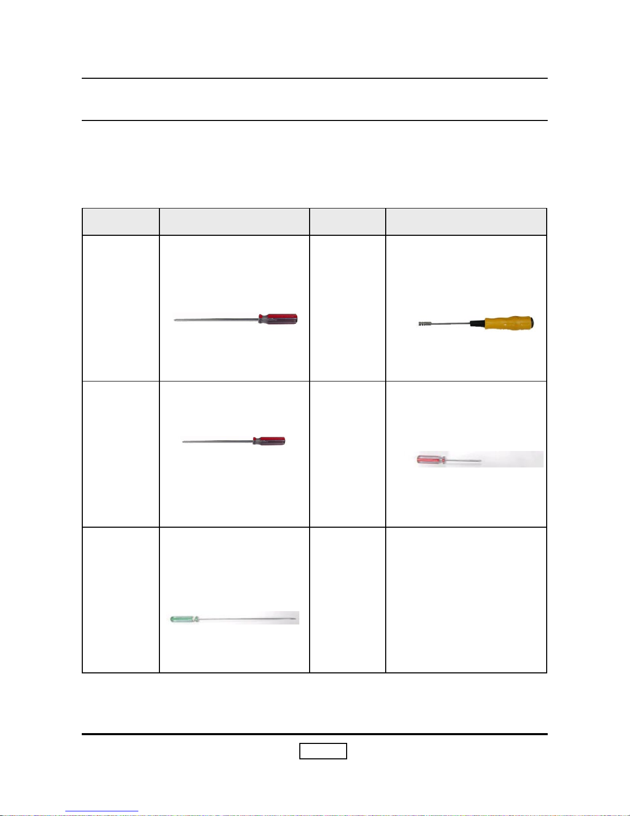
Item Photo Item Photo
Screw Bit
(+) :107
Hex
Sleeves
5mm
Screw Bit
(+) :102
Screw Bit
(+) :101
Screw Bit
(-) :101
2-1 Equipment Needed
Chapter 2
Disassembly Process
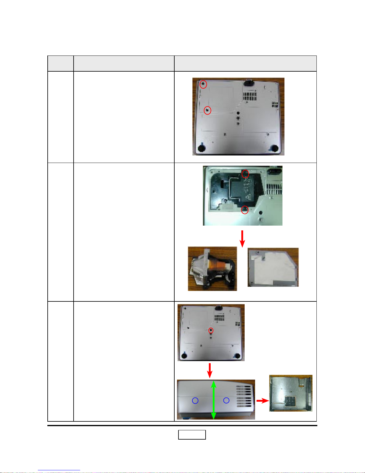
2-2
S8 T8 T9
No Procedure Photo
1 Loosen 2 screws to remove
the Lamp Cover
2 Loosen 2 screws to remove
Lamp Module
3
Unscrew 1 screw and press
the left tenon (A) on the
lower cover first and then
press the right one (B) on
the lower cover to pull the
bilateral sides to remove
Top Cover.
2-2 Disassemble Lamp, Keypad Board, Top Cover and Front
Cover
Lamp Cover
Lamp
A B
Pull
Top Cover
2-3
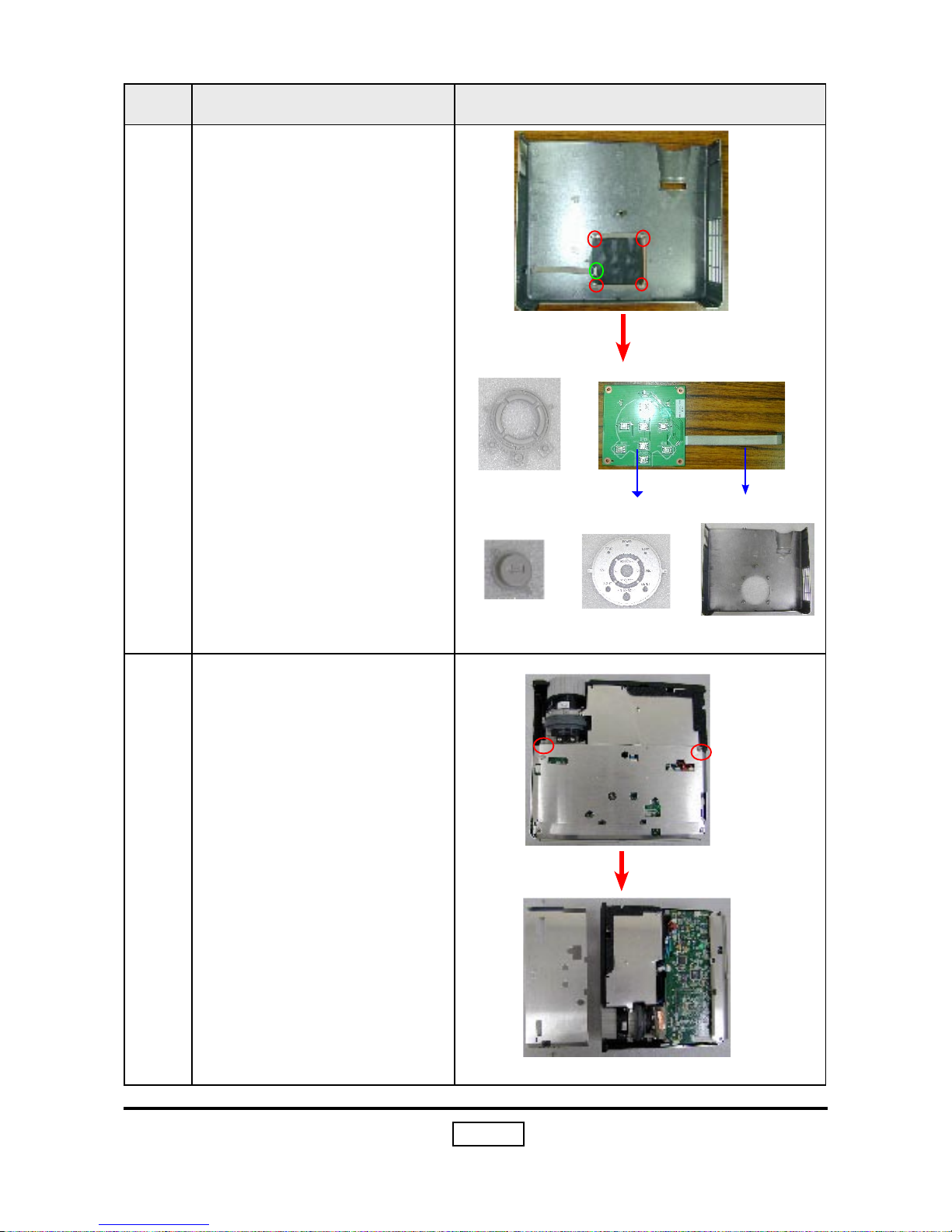
S8 T8 T9
No Procedure Photo
4
Tear off the mylar first. Unplug the FFC cable and unscrew 4 screws to remove
Keypad Button, Enter Key
and Keypad Board.
5
Unscrew 2 screws to remove Top Cover Shielding.
Keypad Button
Keypad Board
Keypad Cap
Top Cover
Top Cover Shielding
FFC Cable
Enter Key
2-4
S8 T8 T9
No Procedure Photo
6
Unscrew 2 screws to remove Lamp Plate.
7
Unplug the red connector
from Main Board, unscrew 1
screw and pull Buttom Cover outwards and pull forward
Front Cover to remove it.
Lamp Iron Plate
Pull
Front Cover
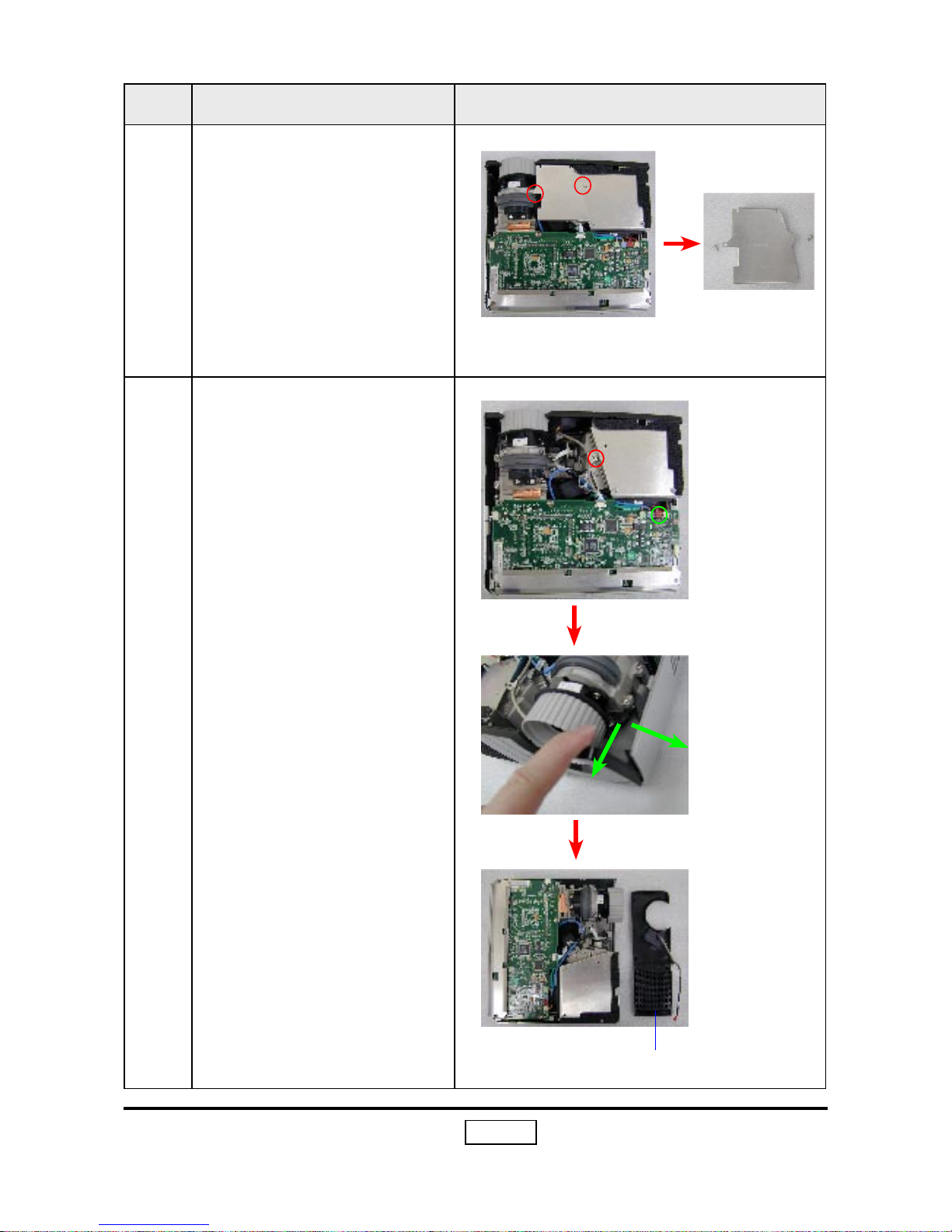
2-5
S8 T8 T9
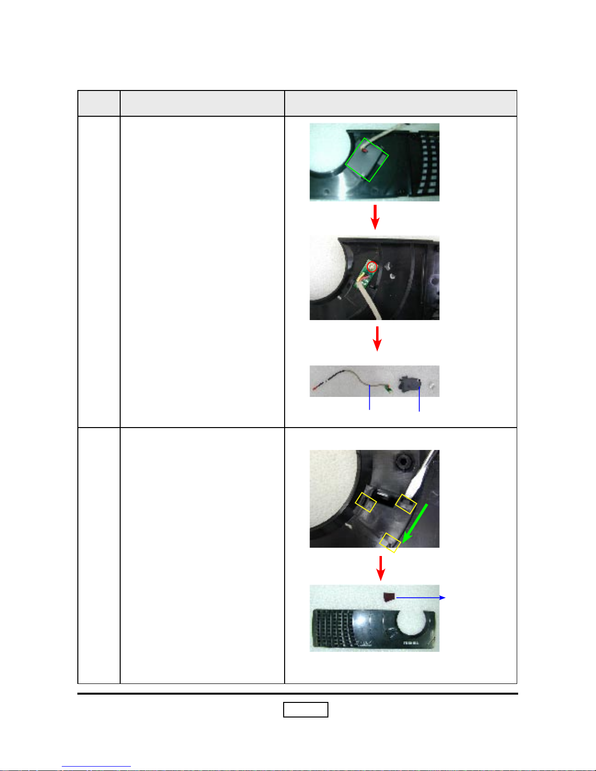
No Procedure Photo
1
Take off the maylar first,
unscrew 1 screw to remove
IR Sensor Board.
2
Push the three tenons to
remove IR Lens and Front
Cover.
IR Sensor Board
Front Cover
Push
2-3 Disassemble
IR Sensor Board, Main Boar
d, I/O Module,
Speaker, Back Cover and Lamp Driver
IR Lens
IR Lens Hood Mylar
2-6
S8 T8 T9
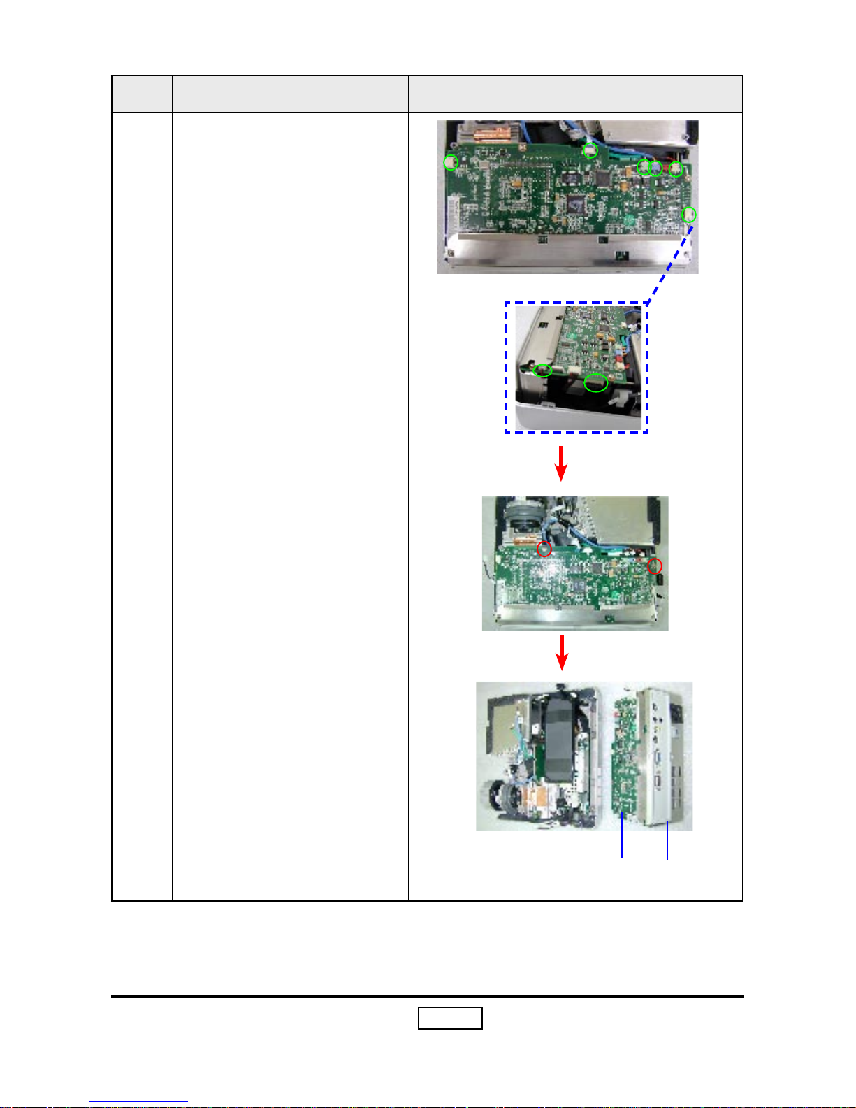
No Procedure Photo
3
Unplug 8 connectors and
unscrew 2 screws to separate Main Board and I/O
Module from the unit..
Main Board
I/O Module
 Loading...