

Toshiba T90S3S08KS6XSN, T90S3S10KS6XSN, T90S3S16KS6XSN, T90S3S22KS6XSN User Manual
UNINTERRUPTIBLE POWER SYSTEMS
3
Extended
G9000 Series
96.5%
Efficiency
Next-Generation IGBT Technology
True On-Line, Double-Conversion UPS
Parallel up to Four Units
Input Power Factor > 0.99
Input Current THD < 3%
Output Power Factor 0.9
100% Unbalanced Load Capability
Wide Input Voltage Range +15%, -20% (Without Utilizing Batteries)
High Efficiency for Lower Operational Cost
Smallest Footprint and Highest Power Density in Industry
Electronic Battery Isolation for Battery Longevity
Generator-Friendly Design and Compatibility
Complete Front-Access for Installation, Operation, and Service
Handles Leading Power Factor Loads (Without Derating)
SNMP/Web-Based Monitoring
Three-Year Warranty for Lower Cost of Ownership
80/100/160/225 KVA UPS

Model Number T90S3S08KS6XSN T90S3S10KS6XSN T90S3S16KS6XSN T90S3S22KS6XSN
Capacity KVA/KW 80/72 100/90 160/144 225/202.5
Topology True On-Line, Double Conversion, Advanced Multi-Level IGBT Technology
Input Voltage 480 V, Three-Phase, Three-Wire + Ground/Bypass Input, 480 V, Three-Phase, Three-Wire + Ground
Voltage Range 480 V, -20% to +15% (384 to 552 V Without Utilizing Battery)
Power Factor Greater than 0.99
Current THD <3% at 100% Load (No Input Filter Required)
Frequency 60 Hz (± 10%)
Output Voltage 480 V, Three-Phase, Three-Wire + Ground
Frequency 60 Hz, ±0.01% (In Free-Running Mode)
Voltage Regulation ±1.0% (0.5% Typical)
Power Factor 0.9 Lagging to 0.95 Leading
Power Factor Range 0.9 to 1.0 Lagging
Voltage THD <2% for Linear Load, <5% for Non-Linear Load
Overload (Inverter) 125% for 2 Minutes; 150% for 60 Seconds
Overload (Bypass) 1000% for One Cycle
Battery DC Link 480 VDC
Ripple Voltage ±0.23% ±0.29%
Environment Temperature Range 32° to 104°F (0° to 40°C)
Relative Humidity 5% to 95% Non-Condensing
Heat Rejection 10,771 BTUs/Hour 13,463 BTUs/Hour 17,821 BTUs/Hour 25,060 BTUs/Hour
Efciency (Full-Load) 95.8% 95.8% 96.5% 96.5%
Efciency (20% Load) 92.5% 92.5% 94.7% 94.9%
Altitude 7380 Feet Maximum Without Derating (2250 Meters)
Audible Noise 69.5 dBA at 1 Meter
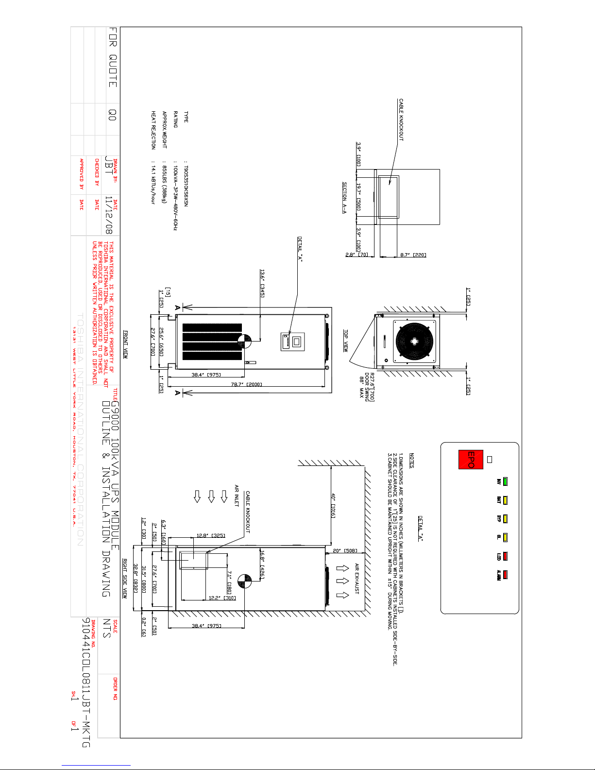
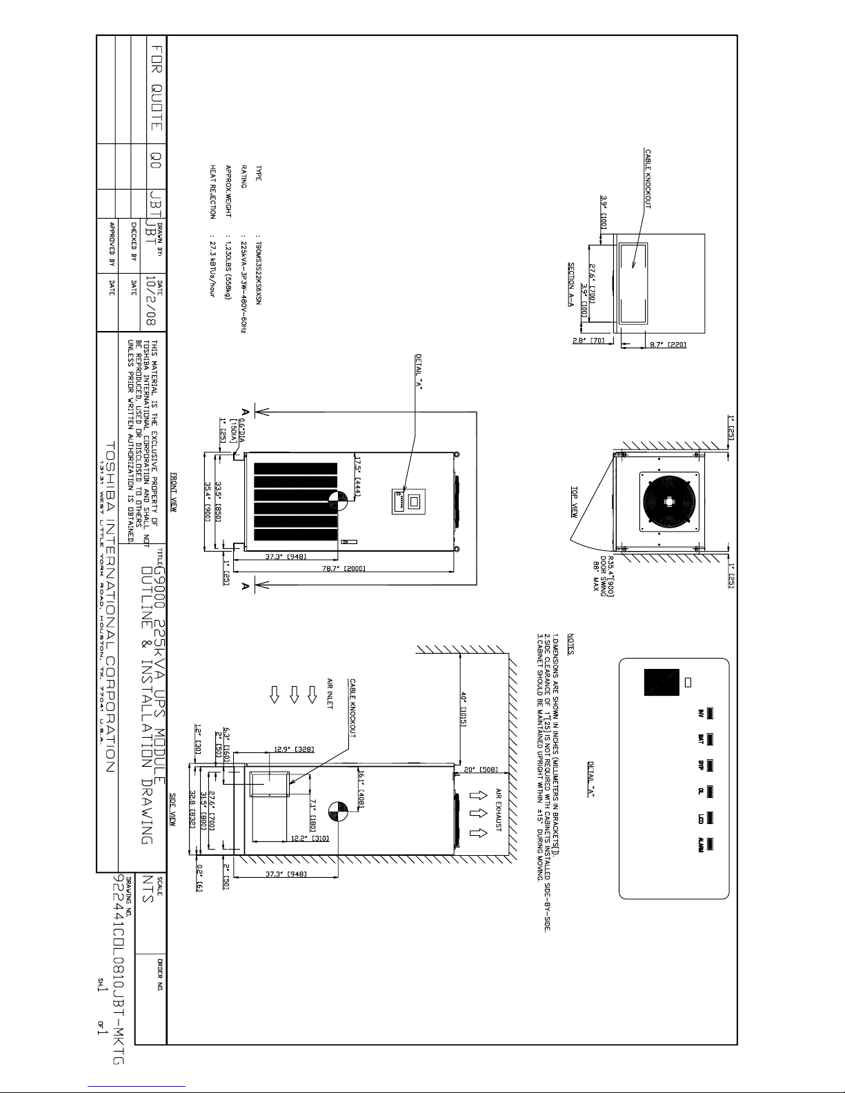
Dimensions Dimensions (W x D x H) 27.6 x 32.8 x 80.6 in.
(700 x 832 x 2047 mm)
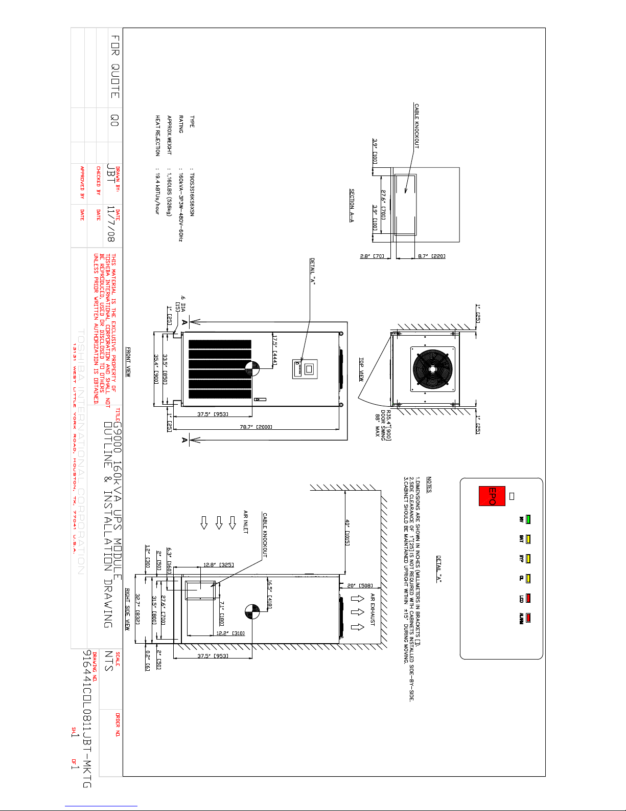
35.4 x 32.8 x 80.6 in.
(900 x 832 x 2047 mm)
Weight 855 lbs. (388 kg) 855 lbs. (388 kg) 1160 lbs. (526 kg) 1230 lbs. (558 kg)
Features Digital Signal Processor (DSP) Control, Fully Digital IGBT Converter & Inverter, High Efciency Over Wide Load Range,
Transformer-Less Design, N+1 and N+N (Up to Four in Parallel) Capability, Dual-Input Feed, Electronic Battery Isolation,
RS232 and Dry Contact Interface, Small Footprint, Lightweight Design
Standards UL 1778, CUL, ISO9001, ISO14001, ANSI C62.41 (IEEE 587), FCC Class A, Article 47, Part 15.B
Warranty Three Years Onsite (Optional Two Year Extended Warranty)
See Toshiba Warranty Policy for Full Details
Service 24-Hour, 365-Day Technical Support 1-877-867-8773
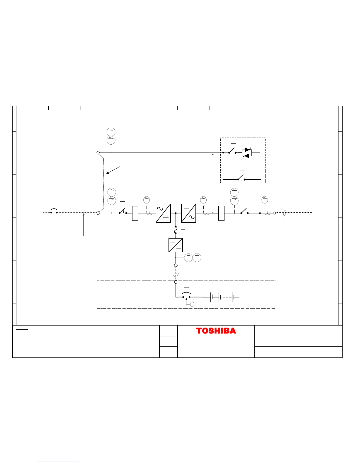
G9000 Series 80/100/160/225 KVA UPS
Bypass Input
480 VAC
Three-Phase,
Three-Wire with
Ground
AC Input
480 VAC
Three-Phase,
Three-Wire with
Ground
Battery
Cabinet
G9000 Series UPS Module
Optional Jumper for Single-Source Input
AC/DC IGBT
Converter
DC/AC IGBT
Inverter
DC/DC IGBT
Chopper
Static Transfer Switch
AC Output
480 VAC
Three-Phase,
Three-Wire with
Ground
UPS ADJUSTABLE SPEED DRIVES MOTORS CONTROLS INSTRUMENTATION PLC
INDUSTRIAL DIVISION
13131 West Little York Road, Houston, Texas 77041
Tel 713/466-0277 Fax 713/466-8773
US 800/231-1412 Canada 800/872-2192 Mexico 001/800/527-1204
www.toshiba.com/ind
Copyright 4/2009 UPS G9000 B05 23 08-002
Two G9000 UPS Modules in
Parallel Conguration
AC
INPUT
UPS #1
UPS #2
Available Through:
TTC
CABINET
AC
OUTPUT
*UPSg9000MMCT093109*

CORPORATE OFFICE
13131 WEST LITTLE YORK ROAD HOUSTON, TX 77041
PHONE: (713) 466-0277 (800) 231-1412
FACSIMILE: (713) 896-5226
TOSHIBA G9000
80/100/160/225 kVA
GUIDE SPECIFICATION
THREE PHASE UNINTERRUPTIBLE POWER SUPPLY
61963-000
March 2009
1

Guide Specification – 3-Phase Static Uninterruptible Power Supply
This Page Intentionally Left Blank
2 March 2009

Guide Specification – 3-Phase Static Uninterruptible Power Supply
Table of Contents
1 SCOPE ......................................................................................................................................................................... 5
1.1 SYSTEM ............................................................................................................................................................................ 5
2 SYSTEM DESCRIPTION ................................................................................................................................................. 5
2.1 APPLICABLE STANDARDS: ..................................................................................................................................................... 5
2.2 COMPONENTS: .................................................................................................................................................................. 5
2.3 SYSTEM OPERATION: .......................................................................................................................................................... 6
2.3.1 Normal ................................................................................................................................................................. 6
2.3.2 Loss of Main Power .............................................................................................................................................. 6
2.3.3 Return of Main Power .......................................................................................................................................... 6
2.3.4 Transfer to Bypass AC source ............................................................................................................................... 6
2.3.5 Maintenance Bypass ............................................................................................................................................ 6
3 GENERAL CONDITIONS FOR INSTALLATION ................................................................................................................. 6
3.1 REQUIRED OUTPUT CAPACITY: .............................................................................................................................................. 6
3.2 UPS ENVIRONMENT: .......................................................................................................................................................... 6
3.2.1 Standard Environmental Parameters ................................................................................................................... 6
3.2.2 Discharge Heat from UPS at full load. ................................................................................................................. 6
3.2.3 Clearances for installation ................................................................................................................................... 7
3.2.4 Cable Access ......................................................................................................................................................... 7
4 SYSTEM PARAMETERS ................................................................................................................................................ 7
4.1 UPS REQUIREMENTS: ......................................................................................................................................................... 7
4.1.1 General Requirements: ........................................................................................................................................ 7
5 FUNCTIONAL DESCRIPTION ......................................................................................................................................... 9
5.1 IGBT RECTIFIER ................................................................................................................................................................. 9
5.2 IGBT DC-DC CONVERTER ................................................................................................................................................... 9
5.3 IGBT INVERTER:............................................................................................................................................................... 10
5.4 STATIC BYPASS CIRCUIT: .................................................................................................................................................... 11
5.5 METERING, MONITORING, ALARMS, AND CONTROLS .............................................................................................................. 12
6 MECHANICAL DESIGN ............................................................................................................................................... 14
6.1 UPS ENCLOSURE .............................................................................................................................................................. 14
6.2 CABLE ACCESS ................................................................................................................................................................. 14
7 WARRANTY .............................................................................................................................................................. 14
7.1 UPS WARRANTY .............................................................................................................................................................. 14
7.2 UPS BATTERY WARRANTY ................................................................................................................................................. 14
7.3 WARRANTY SUPPORT AVAILABILITY ..................................................................................................................................... 14
8 BATTERY CABINETS (OPTION) ................................................................................................................................... 14
9 COMMUNICATIONS (OPTIONAL) .............................................................................................................................. 15
9.1 REMOTEYE II NETWORK ADAPTER ....................................................................................................................................... 15
9.1.1 SNMP Ability ...................................................................................................................................................... 15
9.1.2 HTTP Familiarity ................................................................................................................................................. 15
9.1.3 Shutdown Capability .......................................................................................................................................... 15
9.2 REMOTE STATUS ALARM PANEL (RSAP)............................................................................................................................... 16
10 TOSHIBA DISTRIBUTION CABINET (TDC) (OPTION) .................................................................................................... 16
March 2009 3

Guide Specification – 3-Phase Static Uninterruptible Power Supply
11 MAINTENANCE BYPASS PANEL (OPTION) .................................................................................................................. 16
11.1 SITE INSTALLATION ....................................................................................................................................................... 16
11.2 ELECTRICAL CONFIGURATION ......................................................................................................................................... 16
11.3 MECHANICAL INTERLOCK .............................................................................................................................................. 16
11.4 EXTERNAL MAINTENANCE BYPASS: ................................................................................................................................. 16
12 AUXILIARY TRANSFORMER CABINETS (OPTION) ....................................................................................................... 17
13 POWER DISTRIBUTION UNITS (OPTION) ................................................................................................................... 17
14 EXTENDED SERVICES (OPTION) ................................................................................................................................. 17
4 March 2009

Guide Specification – 3-Phase Static Uninterruptible Power Supply
1 SCOPE
1.1 System
These specifications describe a high efficiency continuous duty, three-phase, on-line, double
conversion, solid-state Uninterruptible Power Supply system (UPS). The UPS shall operate
utilizing the existing power distribution system to provide high quality, uninterruptible power to
critical loads.
The UPS shall consist of an AC/DC multi-level Insulated Gate Bipolar Transistor (IGBT)
Rectifier, DC/DC Converter/Battery Charger, DC/AC multi-level IGBT Inverter, integral static
bypass, front-accessible controls, display, and monitor.
2 SYSTEM DESCRIPTION
2.1 Applicable Standards:
The UPS shall be designed in accordance with and be compliant with the following sections of
the current revisions of the following standards:
UL 1778/cUL Listed
FCC Class A, Article 47, Part 15.B
ISO 9001
ISO 14001
ANSI C62.41
2.2 Components:
The UPS shall consist of the following components:
1. Multi-level IGBT AC/DC Rectifier
2. IGBT DC/DC Battery Converter/Charger
3. Multi-level IGBT DC/AC Inverter
4. Hybrid Integral Static Bypass (Thyristor switch with wrap around contactor)
5. Microprocessor Logic and Control Panel
** The following components shall be optional:
1. Battery Cabinet with DC Breaker
2. Toshiba Distribution Cabinet (TDC)
3. Toshiba Tie Cabinet for parallel operation
4. Maintenance Bypass Panel (Circuit Breaker)
5. RemotEye II UPS remote communications and web-based monitor card
6. Network communications with MODBUS interface adapter
7. Remote Status Alarm Panel (RSAP)
March 2009 5

Guide Specification – 3-Phase Static Uninterruptible Power Supply
2.3 System Operation:
The UPS shall operate as a fully automatic on-line system in the following modes:
2.3.1 Normal
IGBT Rectifier converts AC input power to DC power for the inverter and for charging the
batteries. The IGBT inverter supplies clean and stable AC power continuously to the critical
load. The UPS Inverter output shall be synchronized with the bypass AC source when the
bypass source is within the AC input voltage and frequency specifications.
2.3.2 Loss of Main Power
When Main Power is lost, the batteries shall automatically back up the inverter so there is no
interruption of AC power to the critical load.
2.3.3 Return of Main Power
The system shall recover to the operating mode in Item 1 and shall cause no disturbance to
the critical load while simultaneously recharging the backup battery.
2.3.4 Transfer to Bypass AC source
If the UPS becomes overloaded the UPS controls shall automatically transfer the critical load
from the inverter output to the bypass AC source without interruption. When the overload
condition is removed, after a preset “hold” period the UPS will automatically re-transfer the
critical load from the bypass to the inverter output without interruption of power to the
critical load.
2.3.5 Maintenance Bypass
An optional manual make-before-break maintenance bypass panel may be provided to
electrically isolate the UPS for maintenance or test without affecting load operation.
3 GENERAL CONDITIONS FOR INSTALLATION
3.1 Required Output Capacity:
The UPS will be available in the following output capacities: 80, 100, 160, and 225 kVA (72, 90,
144, and 202.5 kW). Each unit shall be capable of being operated either independently or
connected in parallel for a total of up to four like-capacity units.
3.2 UPS Environment:
3.2.1 Standard Environmental Parameters
Operating Temperature : 32° to 104°F (0° to 40°C)
Operating Humidity : 5 - 95% (Non-condensing)
Altitude : 7400 ft. (2250 m) (without derating)
3.2.2 Discharge Heat from UPS at full load.
80 kVA : 11,300 Btu/Hr
100 kVA : 14,100 Btu/Hr
160 kVA : 19,400 Btu/Hr
225 kVA : 27,300 Btu/Hr
6 March 2009

Guide Specification – 3-Phase Static Uninterruptible Power Supply
3.2.3 Clearances for installation
Ceiling Level : 20” minimum from top of UPS to ceiling
Front : 40” minimum for maintenance
(Local and regional codes may apply)
Bottom : Knockouts for power cable access
Rear : Zero clearance required
Sides : Zero clearance if using bottom cable access
(Standard knockouts for left/right side
cable access )
Base : Channel mounted
3.2.4 Cable Access
80/100/160/225 kVA : Bottom access standard
:Side knockouts for left/right side access standard
(For use with Optional Side Car)
4 SYSTEM PARAMETERS
4.1 UPS Requirements:
4.1.1 General Requirements:
Rated Output Capacity : 80/100/160/225 kVA
(72/90/144/202.5 kW)
AC/DC Rectifier Type : AC/DC multi-level IGBT Rectifier
DC/AC Inverter Type :DC/AC multi-level IGBT Inverter
Inverter
External Dimensions (W) (D) (H)
80 kVA : 27.6 in.x 32.8 in.x 78.7 (80.6*) in.
100 kVA : 27.6 in.x 32.8 in.x 78.7 (80.6*) in.
160 kVA : 35.4 in.x 32.8 in.x 78.7 (80.6*) in.
225 kVA : 35.4 in.x 32.8 in.x 78.7 (80.6*) in.
* Unit height with fan assembly installed
Weight
80 kVA : 855 lbs
100 kVA : 855 lbs
160 kVA : 1160 lbs
225 kVA : 1230 lbs
Paint Color : Black (Munsell N1.5)
4.1.2 AC Input:
Configuration : 3-Phase/3-Wire + Ground
Rated Voltage : 480V
Voltage Variation : +15% to –20%
Rated Frequency : 60Hz
Frequency Variation : +/-10%
March 2009 7

Guide Specification – 3-Phase Static Uninterruptible Power Supply
Input Power Factor : Greater than 0.99 lagging at 25%-115% load
Current THD : 3% maximum THD at 60%–100% load
6% maximum THD at 25%–59% load
(No input harmonic filter required)
4.1.3 Charging Function:
DC Nominal Voltage : 480 V
AC Ripple on DC Bus : < 0.2% of DC Voltage
DC Voltage Range : 400 V to 545 V
DC Float Charging Voltage : 545 V
Maximum charging current:
80 kVA : 20 A
100 kVA : 25 A
160 kVA : 40 A
225 kVA : 56 A
AC Ripple on DC Charging Circuit :
80 kVA : 0.23%
100 kVA : 0.23%
160 kVA : 0.23%
225 kVA : 0.29%
4.1.4 Bypass Input:
Configuration : 3-Phase/3-Wire + Ground
Rated Voltage : 480 V
Input Voltage Synchronous Range : +/-10%
Rated Frequency : 60 Hz
Frequency Variation : +/-5%
Frequency Synchronous Range : +/-1 – 5% (0.6 – 3.0 Hz) Selectable
Bypass Overload Capacity : 1000% for one cycle
4.1.5 AC Output:
Configuration : 3-Phase/3-Wire + Ground
Rated Capacity :80/100/160/225 kVA (72/90/144/202.5 kW)
Rated Voltage : 480 V
Efficiency at % Full Load : 20% 40% 60% 80% 100%
80 kVA 92.5% 95.6% 95.6% 95.6% 95.6%
100 kVA 92.5% 95.6% 95.6% 95.6% 95.6%
160 kVA 94.6% 96.2% 96.2% 96.2% 96.2%
225 kVA 94.7% 96.2% 96.2% 96.2% 96.2%
Voltage Regulation : +/-1% (0-100% Unbalanced Load)
: +/-1% (0-100% Balanced Load)
Voltage Adjustment Range : +/-3%
Rated Frequency : 60 Hz
Frequency Regulation : +/-0.01% (Free-Running Mode)
Frequency Slew Rate : +/-1.0 Hz/s to +/-5.0 Hz/s (Selectable)
8 March 2009

Guide Specification – 3-Phase Static Uninterruptible Power Supply
Rated Load Power Factor : 0.9 PF lagging
Overload Capacity : 125% for 2 min.,
150% for 1 min.
Harmonic Voltage Distortion : 2% maximum THD (100% Linear Load)
: 5% maximum THD (100% Non-linear Load)
Phase Displacement : 1° Maximum at 100% load
Voltage Transients:
100% Load Step Change : +/-2% Maximum (Without battery assistance)
Loss or Return of Input : +/-1% Maximum
Transfer from Bypass to Inverter : +/-5% Maximum
(At Bypass Rated Voltage)
Recovery Time : 20 ms
Crest Factor : 2.3
5 FUNCTIONAL DESCRIPTION
The UPS shall protect the load against surges, sags, undervoltage, and voltage fluctuation. The
UPS shall have built-in protection against permanent damage to itself and the connected load for
all predictable types of malfunctions. The load shall be automatically transferred to the bypass
line without interruption in the event of an internal UPS malfunction. The status of protective
devices shall be indicated on a LCD graphic display screen on the front of the UPS.
5.1 IGBT Rectifier
5.1.1 General
A solid-state, multi-level IGBT Rectifier shall convert the incoming AC power into DC
power to supply the inverter input and system battery.
5.1.2 Voltage Regulation
The rectifier output voltage shall not deviate by more than +/- 1.0% RMS under the
following conditions:
0% - 100% loading (balanced and unbalanced non-transient loading)
+15% – 20% utility voltage change
+/-10.0% utility frequency change
5.1.3 Reflected Harmonic Content
Input current THD shall be
3% maximum at 60%-100% load
6% maximum at 25%-59% load.
5.2 IGBT DC-DC Converter
5.2.1 General
A solid-state IGBT Battery Converter/Charger shall control battery charging.
5.2.2 Battery Charge Current Limit
March 2009 9

Guide Specification – 3-Phase Static Uninterruptible Power Supply
The Converter logic shall provide DC for controlled battery charging. The battery current
sensing shall be independent of the Converter DC Output current sensing to provide
precise battery recharging control. The DC/DC Charging Converter shall include a circuit
to regulate the battery charging current to between 100% and 125% of maximum battery
charging current..
5.2.3 Battery Protection
The converter shall be provided with monitoring and control circuits to protect the battery
system from damage due to excessive discharge. Converter shutdown shall be initiated
when the battery voltage reaches a discharge cutoff voltage of 400 VDC. Automatic
shutdown based on discharge time is not acceptable.
5.2.4 DC Ripple (Without batteries)
AC Ripple on the DC Bus shall be less than 0.2%.
AC Ripple on the Battery charging circuit shall be less than 0.23% for the 80/100/160
kVA UPS, and less than 0.29% for the 225 kVA UPS.
5.3 IGBT Inverter:
5.3.1 General
The inverter shall be composed of multi-level IGBT power transistors controlled utilizing
an Advanced Technology PWM logic. The Inverter shall continuously convert DC power
from the IGBT Rectifier to AC power for the critical loads. When the utility voltage or
frequency exceeds the specified UPS input tolerances, the inverter shall continuously
convert DC power from the battery source to AC power for the critical load.
The inverter shall be capable of providing rated output while operating at any battery
voltage within the battery operating range. When the DC battery voltage reaches the
operational low voltage limit during a loss of utility AC power, the inverter shall
automatically shut off.
5.3.2 Output Voltage
The Inverter output voltage shall not deviate by more than +/- 1.0% RMS under the
following steady state conditions as the Inverter DC input voltage varies from maximum
to cutoff:
0% to 100%Unbalanced load
0% to 100%Balanced load
5.3.3 Synchronization
The Inverter output voltage shall be automatically synchronized with the bypass AC
source as long as the source is within the tolerable frequency and voltage range. If the
bypass AC source is not within the range, the control circuitry will stop synchronization
and operate the inverter in free running mode. When the bypass AC source recovers to
within tolerance, the inverter shall change its frequency (slew rate 1 to 5 Hz/sec,
selectable) and track the bypass AC source until synchronization is achieved without
causing any disturbance to the load.
10 March 2009

Guide Specification – 3-Phase Static Uninterruptible Power Supply
5.3.4 Output Control
The Inverter can be manually started and stopped using the LCD touch screen controls.
5.3.5 Overload Capacity:
The Inverter output shall be capable of providing an overload current of 125% for 2 min.
and 150% for 1 min. A message on the control panel shall indicate this condition. If the
time limit associated with the overload condition expires, or the overload is in excess of
the set current limit, the load power shall transfer to the bypass source without
interruption.
5.4 Static Bypass Circuit:
5.4.1 General:
An integral static bypass circuit shall be provided to supply an alternate source of power
to the critical load in the event the inverter cannot supply rated output power. The bypass
circuit shall be capable of supplying the UPS rated load current and accommodate fault
clearing.
The 100% duty rated static bypass panel shall be composed of a thyristor switch with a
wrap-around contactor. The thyristor switch shall be a high-speed transfer device. The
wrap-around contactor shall be electrically connected in parallel to the thyristor switch
and shall, at the same time as the thyristor switch, be energized and, upon closure,
maintain the bypass source to the load to improve the efficiency and reliability of the
system. The thyristor switch shall only be utilized for the time needed to energize the
contactor closure.
The UPS system logic shall employ sensing which shall cause the thyristor switch to
energize and provide an uninterrupted transfer of the load to the bypass source when any
of the following limitations are exceeded:
Inverter output undervoltage or overvoltage.
Overloads exceeding 125% for 2 min., or 150% for 1 min.
DC circuit undervoltage or overvoltage.
Final discharge voltage of system battery is reached and the bypass source is
present, available, and within tolerance range
Transferring the output from the inverter to the bypass source and vice versa shall be
performed by pressing “START/STOP” icon on the touchscreen display.
March 2009 11

Guide Specification – 3-Phase Static Uninterruptible Power Supply
Operating Mode
Transfer mode
Transfer Type
Synchronized
Unsynchronized
Automatic
Inverter to Bypass
(Overload, Internal Fault)
Uninterrupted
Interrupted
“BYPASS”
switch operated
Inverter to Bypass
Uninterrupted
Interrupted
(forced transfer)
Automatic
Bypass to Inverter
(Auto-Retransfer Mode)
Uninterrupted
Transfer inhibited
“UPS”
switch operated
Bypass to Inverter
Uninterrupted
Transfer inhibited
If the bypass source is beyond the conditions stated below, interrupted transfer shall be
made upon detection of a fault condition.
Bypass voltage greater than + 10%, -10% from the UPS rated output voltage.
Bypass frequency exceeds + 3 Hz from the UPS rated output frequency.
5.4.2 Overload Capacity in Bypass:
Continuous duty : 125% of the system rated capacity
Overload duty : 1000% of ampere rating for 1 cycle.
5.4.3 Retry function:
When an internal warning/failure has been detected, power flow shall automatically
switch from the main circuit (inverter) to the bypass circuit without interruption to the
load. If the internal warning is cleared, UPS shall automatically switch the power flow
from the bypass circuit to the main circuit (inverter) without interruption.
5.5 Metering, Monitoring, Alarms, and Controls
5.5.1 Status Indicators
The Front Panel shall include LED status indicators for the following states:
Load on Inverter
Battery Operation
Load on Bypass
Overload
LCD Fault
UPS Fault
5.5.2 EPO (Emergency Power Off) Button
The Front Panel shall have an Emergency Power Off button (EPO) located on the front
panel that, when pressed, will shut down the UPS.
12 March 2009

Guide Specification – 3-Phase Static Uninterruptible Power Supply
5.5.3 Liquid Crystal Display (LCD) Touch Panel
The Front Panel shall include a LCD touch panel that shall provide performance data,
statistics, and operating conditions. The following metering will be displayed on LCD
touch panel:
AC Input Voltage
AC Input Frequency
AC Output Voltage
AC Output Current
AC Output Frequency
Battery DC Voltage
Battery DC Current
AC Bypass Voltage
AC Bypass Frequency
5.5.4 Mimic Panel
A one-line diagram of the system shall be displayed on the touch panel display panel to
provide a visual status of contactors within UPS. The panel shall display the followings:
AC Input, DC Input
Rectifier in Operation
Inverter in Operation
UPS/Bypass supply
Battery Operating Condition (float charge/discharge)
Fault, Warning
Operation Guidance (LCD Display)
Fault Guidance (LCD Display)
5.5.5 Isolated Control Signals
Ten (10) Normally Open isolated annunciation signal outputs for remote use will be
furnished. Eight (8) alarms shall be user programmable, and shall be factory default set
as follows
Summary Alarm
Output 1: Load on Bypass
Output 2: Load on Inverter
Output 3: Battery Operation
Output 4: Rectifier Operation
Output 5: Battery Low Voltage
Output 6: Overload
Output 7: Spare
Output 8: Total alarm
Output Contactor Closed
Contact rating:
Output: 1 A @ 30 VDC.
Input: 24 VDC
March 2009 13

Guide Specification – 3-Phase Static Uninterruptible Power Supply
UPS module accepts remote switches to initiate the following remote operations. These
contacts shall be field supplied):
Remote Start
Remote Stop
Battery Temperature High
Power Demand
Remote Emergency Power Off (EPO)
Contact rating:
Input: 24 VDC
The contact signal inputs and outputs shall be wired to a terminal block located inside the
UPS.
6 MECHANICAL DESIGN
6.1 UPS Enclosure
The UPS shall be a freestanding NEMA1 enclosure equipped with a leveling channel base. The
enclosure shall include provisions for hoisting, jacking, and forklift handling.
6.2 Cable Access
Cable access to the UPS shall be
Bottom entry
Side entry when using optional side cabinet
Top entry when using optional side cabinet
7 WARRANTY
7.1 UPS Warranty
The UPS shall come with a 36-month warranty on all mechanical, electrical, electronic
components. Parts, labor, and travel are included during warranty period. Optional extended
warranties shall be available.
7.2 UPS Battery Warranty
The back-up batteries shall come with a ten-year warranty: three years full, then prorated over the
remaining seven years.. Parts, labor, and travel are included during warranty period. Optional
extended warranties shall be available. See Toshiba warranties at www.toshiba.com/ind
7.3 Warranty Support Availability
Warranty and technical support shall be available 24/7/365. (877-867-8773)
8 BATTERY CABINETS (OPTION)
The UPS manufacturer can provide optional matching battery cabinets with DC breaker.
14 March 2009

Guide Specification – 3-Phase Static Uninterruptible Power Supply
Network Adapter/External Hardware
AMD 188ES-20MHz
512kB SRAM: 512kB Flash
Two asynchronous serial ports
10 BaseT RJ-45 connector
Toshiba UPS communication protocol
SNMP over UDP/IP : HTTP over TCP/IP:ARP, RARP, TFTP and
ICMP
MIB_II : Toshiba v1.2_MIB :JEM MIB : RFC 1628
Traffic LED for network : Status LED for status : Power LED for
Power
2 digit (default setting is Switches 1 and 2 off)
Temperature Range: 0 – 40 C
Relative Humidity: 10 – 80 %
Power Requirements: 12 VDC ungrounded
2.0 Watts Maximum
Dimensions: 5.28”(134mm) x 3.40”(86mm) x 1.10”(27mm) (LxWxH)
Weight: 0.38lbs(170g)
Certifications: FCC class A, UL, CUL, CE
9 COMMUNICATIONS (OPTIONAL)
9.1 RemotEye II Network Adapter
The UPS shall provide either an internal or external support for an internet web/SNMP adapter
RemotEye II. for the optional capability of remote or internet system monitoring.
9.1.1 SNMP Ability
RemotEye II shall provide a SNMP interface for the UPS. The SNMP interface shall provide
for easy integration of UPS management into an existing SNMP Network Management
System. At any given time, SNMP queries shall be able to poll the RemotEye II agent for the
current status of its connected UPS.
9.1.2 HTTP Familiarity
The RemotEye II shall provide a HTTP interface for the UPS to allow easy access of the UPS
information from any machine with a web browser. At any time, a network workstation or
management station shall be able to open a RemotEye II website. RemotEye II website shall
enable the UPS system information to be configured and monitored remotely. RemotEye II
shall provide access to 3 java applets for monitoring, event logging, and trend analysis.
9.1.3 Shutdown Capability
The RemotEye II application software shall allow RemotEye II to remotely notify and
shutdown selected network servers.
March 2009 15

Guide Specification – 3-Phase Static Uninterruptible Power Supply
9.2 Remote Status Alarm Panel (RSAP)
The manufacturer shall optionally provide a RSAP that shall provide a wall-mounted LED mimic
display for UPS status events of:
Input ON
Bypass ON
Inverter ON
Low Battery, AC Fail
New alarm annunciation
Battery backup for the RSAP monitor.
10 TOSHIBA DISTRIBUTION CABINET (TDC) (OPTION)
The manufacturer can optionally provide a matching TDC for the UPS.
The TDC can include a step-down, 480/208/120 V transformer in a matching NEMA1
cabinet.
The TDC can include a three-breaker MBS with a slidebar interlock. Interlock keys and
Solenoid Key-Retractable Unit (SKRU) can be provided.
The TDC can include up to eight 225 A sub-feed breakers.
The TDC can include up to two 42-pole distribution panels.
11 MAINTENANCE BYPASS PANEL (OPTION)
The manufacturer can optionally provide a MBS (Maintenance Bypass Panel) for the UPS.
11.1 Site Installation
The MBS can be available in either a wall mount or floor mount configuration.
11.2 Electrical Configuration
The MBS can be available in two, three, or four breaker configurations.
11.3 Mechanical Interlock
The MBS can have the option for a two-kirk-key interlock system.
11.4 External Maintenance Bypass:
A manually operated maintenance bypass panel can be provided to bypass the power
feeding the critical load from inverter to a static switch panel without causing any power
interruption.
Bypass input breaker can supply input power to the UPS module static bypass input. If
the system design calls for separate UPS and bypass inputs, a bypass input breaker can be
installed on each input.
UPS maintenance bypass breaker can allow power flow to the load when the UPS is
bypassed. This can be a normally open circuit breaker.
The UPS module output can feed the UPS output isolation breaker.
Optionally, the two input bypass breaker can be used to feed both the UPS converter input
and the UPS bypass input.
16 March 2009

Guide Specification – 3-Phase Static Uninterruptible Power Supply
12 AUXILIARY TRANSFORMER CABINETS (OPTION)
The UPS manufacturer can provide optional Auxiliary Transformer Cabinets (ATC) for stepping
the UPS output voltage down to service load voltages.
13 POWER DISTRIBUTION UNITS (OPTION)
The UPS manufacturer shall provide optional PDUs (Power Distribution Units) for stepping the
UPS output voltage down to service load voltages. The PDUs can be provided in either frontaccess cabinet or Rack-mount style.
14 EXTENDED SERVICES (OPTION)
The UPS manufacturer can offer :
Startup Service
Maintenance Contracts (Silver, Gold, Platinum)
Preventive Maintenance Contracts
Spare-parts kits (A, B, and C level)
Extended warranty coverage for up to an additional 2 years
Enhanced warranty contract (24/7 + Holiday coverage)
Load bank testing
Factory witness testing
Site monitor and power audits
March 2009 17

DC CONV
UPS Cabinet
SYNC
RECT
A
V
Hz
V A
V
Hz
Output
480V
3Ph/3W,
60Hz,
80 kVA
Customer Utility Supply
One-Line Diagram
80 kVA G9000 Series UPS
480V Single Input, 480V Output
T90S3S08KS6XSN 0.0
THY. SW.
Static Bypass
CB1
F30
INV
52C
52S
CB3
Customer
supplied
wiring
Customer
supplied
wiring
V
Hz
Primary
AC Input
480V,
3Ph/3W,
60Hz
1) This drawing is for illustration purposes only and is subject to change without notice. TIC
is not responsible for any errors or omissions.
480 VDC
Nominal
Battery Cabinet with Main Breaker
72B
+-
ST
TITLE
DRAWING NO. REV.
NOTES
A B C D E F G H I J
1
2
3
4
5
6
7
8
9
10
1
2
3
4
5
6
7
8
9
10
INTERNATIONAL CORPORATION
Houston Texas, USA
THIS MATERIAL IS THE EXCLUSIVE PROPERTY OF
TOSHIBA INTERNATIONAL CORPORTION AND SHALL NOT
BE REPRODUCED, USED, OR DISCLOSED TO OTHE RS
UNLESS PRIOR WRITTEN AUTHORIZATION IS OBTAINED.
Drawn by
EKM
Date 11/04/08
Approved by
AA
High
Freq.
Filter
High
Freq.
Filter
Jumper Installed for Single
Input


DC CONV
UPS Cabinet
SYNC
RECT
A
V
Hz
V A
V
Hz
Output
480V
3Ph/3W,
60Hz,
100 kVA
Customer Utility Supply
One-Line Diagram
100 kVA G9000 Series UPS
480V Single Input, 480V Output
T90S3S10KS6XSN 0.0
THY. SW.
Static Bypass
CB1
F30
INV
52C
52S
CB3
Customer
supplied
wiring
Customer
supplied
wiring
V
Hz
Primary
AC Input
480V,
3Ph/3W,
60Hz
1) This drawing is for illustration purposes only and is subject to change without notice. TIC
is not responsible for any errors or omissions.
480 VDC
Nominal
Battery Cabinet with Main Breaker
72B
+-
ST
TITLE
DRAWING NO. REV.
NOTES
A B C D E F G H I J
1
2
3
4
5
6
7
8
9
10
1
2
3
4
5
6
7
8
9
10
INTERNATIONAL CORPORATION
Houston Texas, USA
THIS MATERIAL IS THE EXCLUSIVE PROPERTY OF
TOSHIBA INTERNATIONAL CORPORTION AND SHALL NOT
BE REPRODUCED, USED, OR DISCLOSED TO OTHE RS
UNLESS PRIOR WRITTEN AUTHORIZATION IS OBTAINED.
Drawn by
EKM
Date 11/04/08
Approved by
AA
High
Freq.
Filter
High
Freq.
Filter
Jumper Installed for Single
Input
DC CONV
UPS Cabinet
SYNC
RECT
A
V
Hz
V A
V
Hz
Output
480V
3Ph/3W,
60Hz,
160 kVA
Customer Utility Supply
One-Line Diagram
160 kVA G9000 Series UPS
480V Single Input, 480V Output
T90S3S16KS6XSN 0.0
THY. SW.
Static Bypass
CB1
F30
INV
52C
52S
CB3
Customer
supplied
wiring
Customer
supplied
wiring
V
Hz
Primary
AC Input
480V,
3Ph/3W,
60Hz
1) This drawing is for illustration purposes only and is subject to change without notice. TIC
is not responsible for any errors or omissions.
480 VDC
Nominal
Battery Cabinet with Main Breaker
72B
+-
ST
TITLE
DRAWING NO. REV.
NOTES
A B C D E F G H I J
1
2
3
4
5
6
7
8
9
10
1
2
3
4
5
6
7
8
9
10
INTERNATIONAL CORPORATION
Houston Texas, USA
THIS MATERIAL IS THE EXCLUSIVE PROPERTY OF
TOSHIBA INTERNATIONAL CORPORTION AND SHALL NOT
BE REPRODUCED, USED, OR DISCLOSED TO OTHE RS
UNLESS PRIOR WRITTEN AUTHORIZATION IS OBTAINED.
Drawn by
EKM
Date 11/04/08
Approved by
AA
High
Freq.
Filter
High
Freq.
Filter
Jumper Installed for Single
Input

DC CONV
UPS Cabinet
SYNC
RECT
A
V
Hz
V A
V
Hz
Output
480V
3Ph/3W,
60Hz,
225 kVA
Customer Utility Supply
One-Line Diagram
225 kVA G9000 Series UPS
480V Single Input, 480V Output
T90S3S22KS6XSN 0.0
THY. SW.
Static Bypass
CB1
F30
INV
52C
52S
CB3
Customer
supplied
wiring
Customer
supplied
wiring
V
Hz
Primary
AC Input
480V,
3Ph/3W,
60Hz
1) This drawing is for illustration purposes only and is subject to change without notice. TIC
is not responsible for any errors or omissions.
480 VDC
Nominal
Battery Cabinet with Main Breaker
72B
+-
ST
TITLE
DRAWING NO. REV.
NOTES
A B C D E F G H I J
1
2
3
4
5
6
7
8
9
10
1
2
3
4
5
6
7
8
9
10
INTERNATIONAL CORPORATION
Houston Texas, USA
THIS MATERIAL IS THE EXCLUSIVE PROPERTY OF
TOSHIBA INTERNATIONAL CORPORTION AND SHALL NOT
BE REPRODUCED, USED, OR DISCLOSED TO OTHE RS
UNLESS PRIOR WRITTEN AUTHORIZATION IS OBTAINED.
Drawn by
EKM
Date 11/04/08
Approved by
AA
High
Freq.
Filter
High
Freq.
Filter
Jumper Installed for Single
Input
UNINTERRUPTIBLE POWER SYSTEM (UPS)
G9000 SERIES
INSTALLATION AND
OPERATION MANUAL
480/480 V 80/100/160/225 kVA
Document: GBH0016 Rev. 0.21
P/N 61480-000
April 2009

G9000 Installation and Operation Manual

G9000 Installation and Operation Manual
G9000 SERIES
INSTALLATION AND OPERATION MANUAL
480/480 V 80/100/160/225 kVA
Document No. GBH0016 Rev. 0.21
P/N 61480-000
April 2009
 Loading...