

Toshiba T6600C User Manual

1.1 Features
The Toshiba T6600C is one of the most powerful multimedia capable laptop computer’s
available. Utilizing advanced technology and high-speed components, the T6600C offers
excellent display legibility, and IBM PC/AT compatibility. The T6600C system unit consists
of the following features:
❑ Microprocessor
The i486DX2-66 microprocessor operates at 66 MHz.
❑ Math co-processor
The microprocessor (i486DX2) incorporates a math co-processor.
❑ Cache memory
Eight (8) KB of cache memory is stored in the i486DX2.
Optionally, a turbo cache module (128 KB) made by Integrated Device Technology
(IDT) can be installed in the T6600C. When it is installed, the i486DX2 cache memory
is duplicated.
❑ Disk storage
The internal 3.5-inch 510 Megabyte (MB) Hard Disk Drive (HDD) has an average
access time of 10 milliseconds. A 3.5-inch Floppy Disk Drive (FDD) supports 2HD
floppy disks (1.44 Mbytes) and 2DD floppy disks (720 Kbytes). The T6600C also has
a built-in 5.25-inch bay for an optional CD-ROM.
❑ Memory
The T6600C comes standard with 8 MB of CMOS Random Access Memory (RAM).
This includes 640 KB of conventional memory and 7,424 KB of extended memory,
which can be utilized as a BIOS ROM data copy area, and as expanded memory that is
compatible with the Lotus/Intel/Microsoft Expanded Memory Specifications (LIMEMS).
❑ Display
The high-resolution, Thin Film Transistor (TFT) color Liquid Crystal Display (LCD)
displays 640x480 pixels with 260 K colors for both graphics and characters.
The internal display controller supports Video Graphics Adapter (VGA) functions on
the internal display device and Super VGA (SVGA) functions on an external CRT.
The internal LCD and an external CRT can display simultaneously. The Toshiba
proprietary 640x400 mode and AT&T proprietary 640x400 mode are supported at the
BIOS level.
T6600C, T6600C/CD, T6600C/CDV 1-1

1-2
❑ Keyboard
The easy-to-use 101/102-key enhanced detachable keyboard with full-size keys and
standard spacing is compatible with IBM standard software.
❑ Power supply
The power supply is a universal, auto-sensing power supply which enables worldwide
usage of the T6600C as long as a compatible AC plug is available.
❑ Expansion slots
The two Industry Standard Architecture (ISA) bus slots allow for an IBM-compatible
full-size card and half-size cards.
❑ Memory card slots
Two optional memory card slots (88-pin) enable you to install the following Toshiba
optional memory cards:
4 MB memory card: PA2004U
8 MB memory card: PA2005U
16 MB memory card: PA2010U
❑ Personal Computer Memory Card International Association (PCMCIA) card slot
The optional built-in PCMCIA slot measures 16 mm high.
❑ Parallel port
The Centronics-compatible parallel interface port serves two purposes: the port can
be used to connect a Centronics-compatible printer or an external 5.25-inch floppy
disk drive.
❑ RS-232-C port
The RS-232-C port is a 9-pin serial interface port.
❑ Mouse port
The 6-pin mouse port on the back supports an IBM PS/2 mouse.
❑ Keyboard port
The 6-pin keyboard port on the back supports an IBM PS/2-compatible keyboard.
T6600C, T6600C/CD, T6600C/CDV

1-3
❑ RGB port
The 15-pin RGB analog port on the back supports an external CRT.
❑ SCSI port
The T6600C has a Small Computer System Interface (SCSI) port.
❑ Audio ports
The computer has the following standard 3.5-mm diameter miniature stereo jacks for
an audio system:
• Headphone (with speaker shut-off switch)
• Line out
• Line in
• Microphone
❑ Special ports
The T6600C has a Feature connector and Z-connector for use with expansion cards.
T6600C, T6600C/CD, T6600C/CDV
1-4
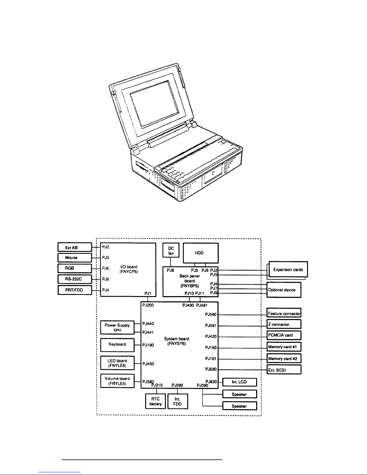
The T6600C Personal Computer is shown in Figure 1-1, and its system configuration is
illustrated in Figure 1-2.
Figure 1-1 T6600C Personal Computer
Figure 1-2 T6600C System Unit Configuration
T6600C, T6600C/CD, T6600C/CDV
1-5
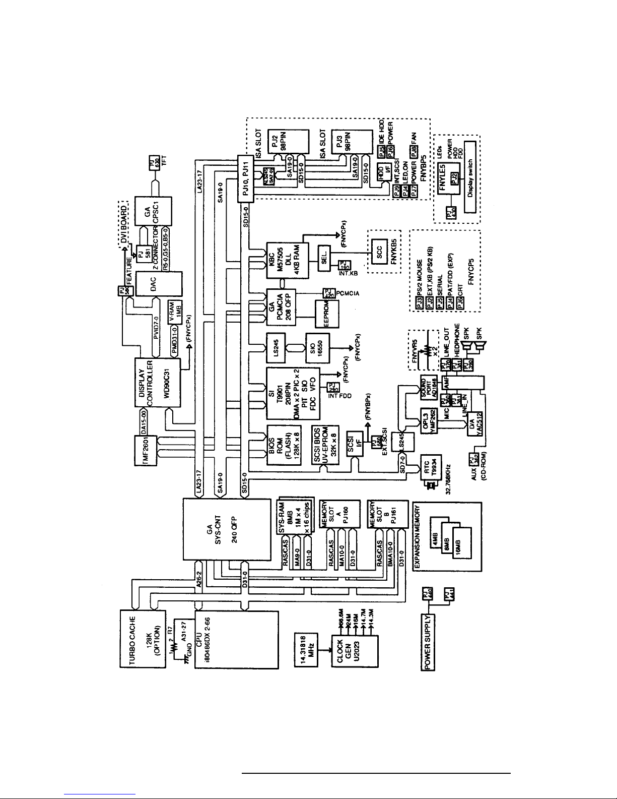
1.2 System Unit Block Diagram
Figure 1-3 shows a block diagram of the T6600C system unit.
Figure 1-3 T6600C System Board Block Diagram
T6600C, T6600C/CD, T6600C/CDV

1-6
The block diagram shown in Figure 1-3 is composed of the following major components:
❑ An i486DX2-66 CPU which incorporates a math co-processor and 8 KB cache
memory.
❑ The following memory components:
Standard RAM: 8 MB, 32-bit data width (70 ns)
Cache memory: 8 KB (inside CPU), a turbo cache memory module can be
installed, duplicating the CPU’s cache memory.
System, Video 128 KB (96 KB are used), 8-bit data width
BIOS: 1 Mbit flash ROM. (150 ns)
This ROM contains Initial Reliability Test (IRT), Basic Input/
Output System (BIOS), and video BIOS.
SCSI BIOS: 32 KB (16 KB are used), 8-bit data width
EROM is used. (150 ns)
Video RAM: 1 MB, 16-bit data width
(Eight 256Kx4 bit chips)
Memory card: 4, 8, or 16 MB memory card can be installed.
32-bit data width.
❑ Super Integration (SI) T9901, which stores the following components:
• Two Direct Memory Access Controllers (DMAC): . 82C37 equivalent
• Two Programmable Interrupt Controllers (PIC): ..... 82C59 equivalent
• One Programmable Interval Timer (PIT):................ 82C54 equivalent
• One Floppy Disk Controller (FDC): ........................ TC8565 equivalent
• One Serial Input/Output Controller (SIO): .............. TC8570 equivalent
(The T6600C does not use SIO inside the T9901.)
• One Variable Frequency Oscillator (VFO):.............. TC8568 equivalent
• One I/O Controller
• One Printer Port Controller
• One Speaker Controller
❑ Serial Input/Output Controller (SIO)
One NS16550 chip controls the internal serial port.
❑ Real Time Clock (RTC)
One T9934 chip is used (which has 128 bytes of memory). Fourteen bytes of memory
are used for the calendar and clock, and the remaining 114 bytes are used for system
configuration data.
T6600C, T6600C/CD, T6600C/CDV

1-7
❑ Keyboard Controller (KBC)
An M37506E1FP chip and an 8749 chip are used.
The M37506E1FP is a keyboard interface controller which controls the internal
keyboard, external keyboard port, and PS/2 mouse port. The 8749 chip is a keyboard
scan controller which is mounted inside the detachable keyboard unit.
❑ VGA Display Controller: WD90C31
This controller controls both internal and external VGA-compatible displays and
external SVGA-compatible displays with an Analog Digital Converter (DAC). The
controller can display data on the internal and external display simultaneously.
❑ SCSI Controller
An AIC6260 chip controls the internal Small Computer System Interface (SCSI) port.
❑ Sound Controller
An AD1848 chip controls the internal sound system.
❑ The Clock Generator receives 14.31818 MHz (X1) and generates the following
frequencies:
• 66 MHz for the CPU
• 14.7456 MHz for the COM
• 24 MHz for the FDC and VFO
• 16 MHz is used for KBC (8 MHz)
• 14.31818 MHz for VGA display controller
OSC (X3) generates 32.768 KHz for RTC
OSC (X) generates 24.576 MHz for sound system
OSC (X) generates 16.9344 MHz for sound system
❑ Gate Arrays
System Controller Gate Array
This gate array has the following functions:
• CPU Control
• Turbo Cache Control
• Memory Control
- DRAM Control
- Compatible Bus Interface Control
• Bus Controller
- Compatible Bus Interface Control
- Compatible Access Control
- DMAC Control
- I/O Control
T6600C, T6600C/CD, T6600C/CDV

1-8
• Address Latch Controller
- 32-bit to 16-bit Transfer
- Address Latch
- DMA Address Generation
- Refresh Address Generation
• I/O Register
- Compatible I/O Port
- Saving the data of the Register (in resume) Control
- Toshiba Special Register
• Processing Speed Control
• Data Bus Change Controller
• Data Latch
PCMCIA Controller Gate Array
This gate array has the following functions:
• PCMCIA Card Interface control
• HDD and FDD access control by security register
• Communication control between system and KBC
• EEPROM access
• SCSI interrupt control
• External SIO control
• Sound system control
• Display type determine
• DAC digital output on/off control
• Display signal on/off control
• Back light on/off control
• Feature connector and Z-connector connect detection
• External KB select signal control
Display Timing Controller Gate Array
This gate array controls the display timing of the internal display.
T6600C, T6600C/CD, T6600C/CDV
1-9
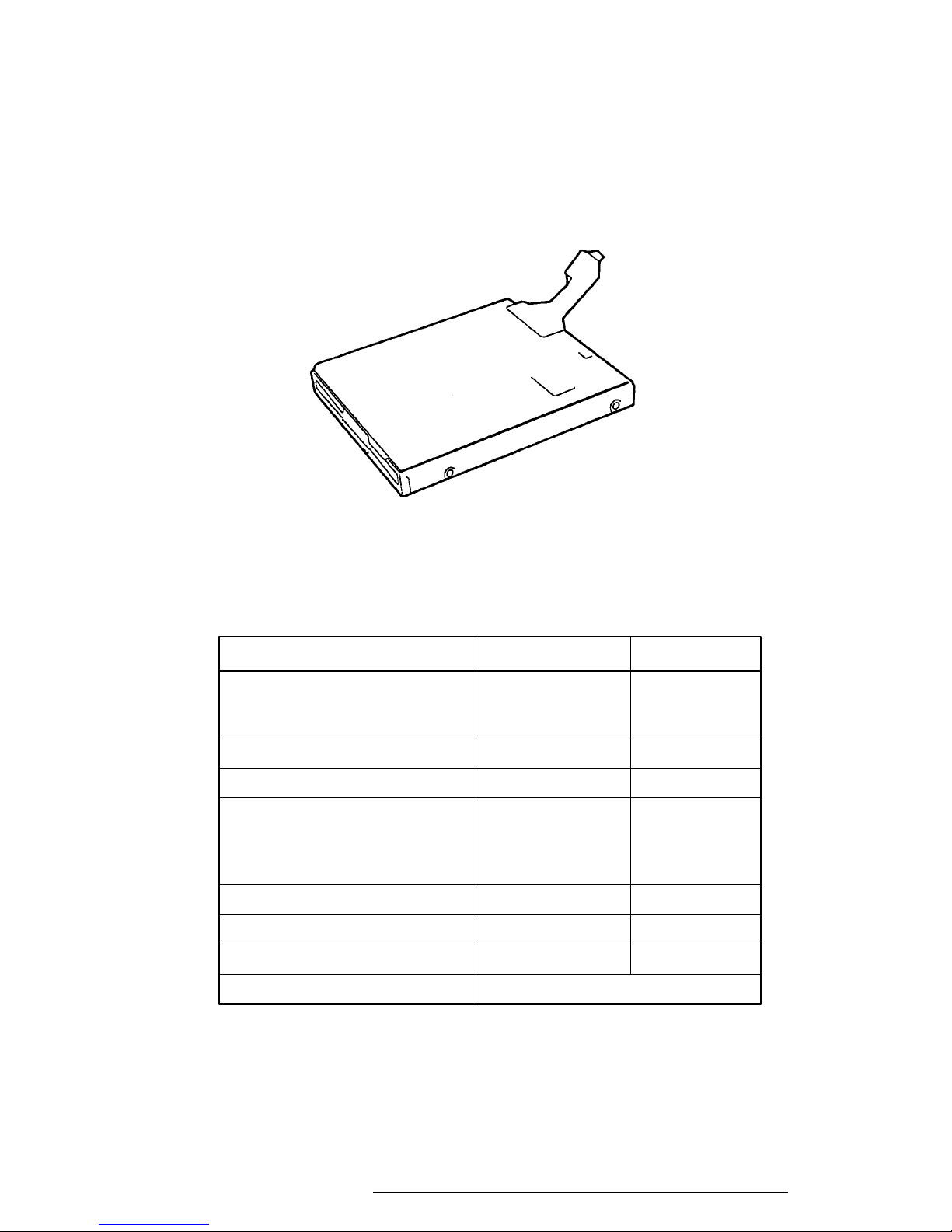
1.3 3.5-inch Floppy Disk Drive
The T6600C 3.5-inch Floppy Disk Drive (FDD) is a thin, high-performance reliable drive that
supports 720 KB (formatted) 2DD and 1.44 MB (formatted) 2HD 3.5-inch floppy disks.
The T6600C FDD is shown in Figure 1-4, and its specifications are described in Table 1-1.
Figure 1-4 3.5-inch FDD
Table 1-1 3.5-inch FDD Specifications
Item 2 MB Mode 1 MB Mode
Storage capacity (KB)
Unformatted 2,000 1,000
Formatted 1,440 720
Number of heads 2 2
Number of cylinders 80 80
Access time (ms)
Track to track 3 3
Average 181 181
Head settling time 15 15
Recording track density (tpi) 135 135
Data transfer rate (Kbps) 500 250
Rotation speed (rpm) 300 300
Recording method Modified Frequency Modulation (MFM)
T6600C, T6600C/CD, T6600C/CDV
1-10
1.4 3.5-inch Hard Disk Drive
The Hard Disk Drive (HDD) is a random access, non-volatile storage device. It has a nonremovable 3.5-inch magnetic disk and mini-Winchester type magnetic heads.
The T6600C supports a 510 MB HDD. The disk drive is shown in Figure 1-5, and its specifications are described in Table 1-2.
Figure 1-5 3.5-inch HDD
Table 1-2 3.5-inch HDD Specifications
Item Specification
Model Name CP30544
Storage capacity (MB)
Formatted 510.0
Number of disks 3
Data heads 6
Data surfaces 6
Tracks per surface 2243
Sectors per track 59 (60) to 89 (90)
Bytes per sector 512 to 520
Access time (ms)
Track to track 2
Average 10
Maximum 18
Rotation speed (rpm) 5,400
Data transfer rate (bps)
To/from media 3.22 M
Recording method 1-7 RLL
Interleave 1:1
T6600C, T6600C/CD, T6600C/CDV
1-11
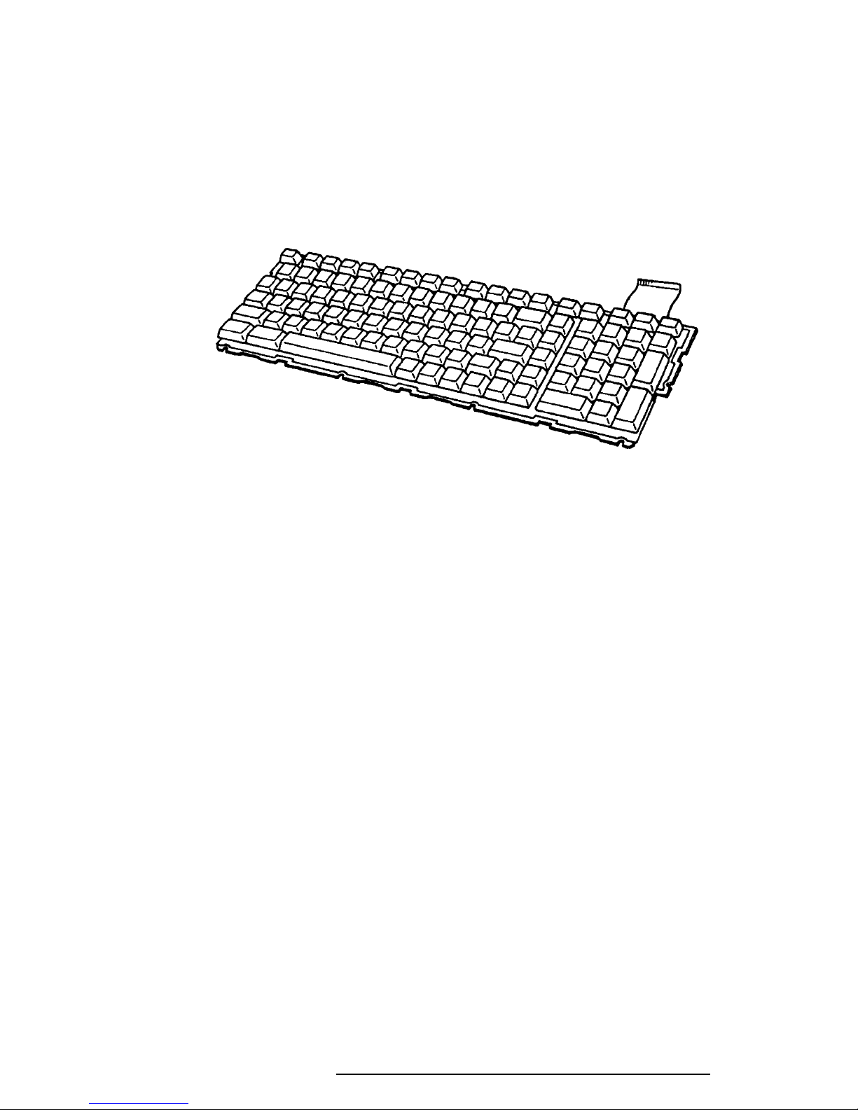
1.5 Keyboard
The 101-key (USA) or 102-key (European) keyboard is mounted on the T6600C’s system
unit, and is connected to the keyboard controller on the system board through a 19-pin flat
cable. The keyboard is shown in Figure 1-6.
See Appendix F for optional keyboard configurations.
Figure 1-6 Keyboard
T6600C, T6600C/CD, T6600C/CDV
1-12
1.6 Display
The T6600C display is a TFT Color Liquid Crystal Display (LCD) which contains an LCD
module, a Fluorescent Lamp (FL), and an FL inverter board.
1.6.1 TFT Color LCD Module
The T6600C TFT color LCD is backlit and supports 640x480 pixels with a High Resolution
Graphics Subsystem (HRGS) and 260 K colors for graphics and characters. The HRGS
includes the functions of the Video Graphics Array (VGA).
The LCD receives vertical and horizontal synchronizing signals, 9-bit data signals, data enable
signals, and shift clock for data transmission. All signals are CMOS-level compatible.
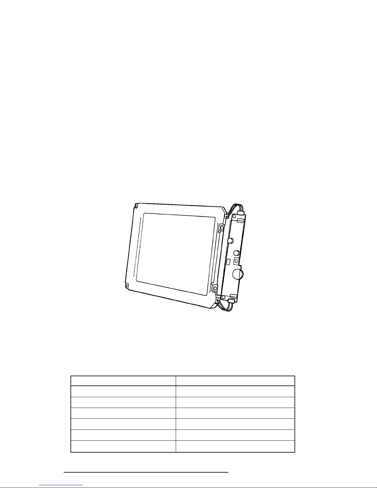
The TFT LCD and FL inverter board are shown in Figure 1-7, and specifications for the LCD
are described in Table 1-3.
Figure 1-7 TFT Color LCD and FL Inverter Board
Table 1-3 TFT Color LCD Specifications
Item Specifications
Number of Dots (dots) 640 x 480
Dot pitch (mm) 0.33 (W) x 0.33 (H)
Display area (mm) 211.2 (W) x 158.4 (H)
Contrast 60:1 (minimum)
FL current (mA) 7.0
FL frequency (KHz) 20 to 60
T6600C, T6600C/CD, T6600C/CDV
1-13
1.6.2 Fluorescent Lamp (FL) Inverter Board
The FL inverter board supplies high frequency current to the LCD’s Fluorescent Lamp.
Specifications for the FL inverter are described in Table 1-4.
Table 1-4 FL Inverter Board Specifications
Item Specifications
Input Voltage (VDC) 24
Power (W) 12.5
Output Voltage (VAC) 1,100 r.m.s
Current (mA) 7 mA r.m.s
Frequency (KHz) 36
Current limits(mA) 5.0 to 7.0
T6600C, T6600C/CD, T6600C/CDV
1-14
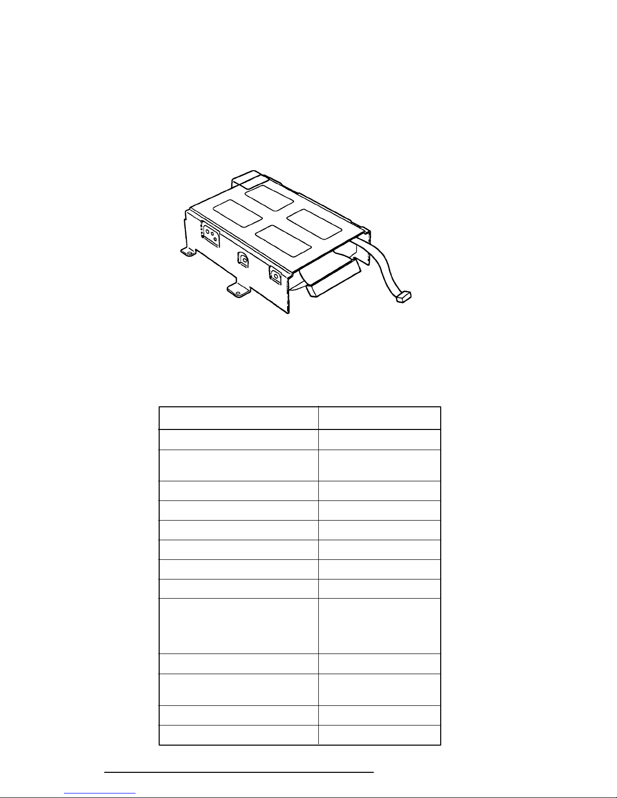
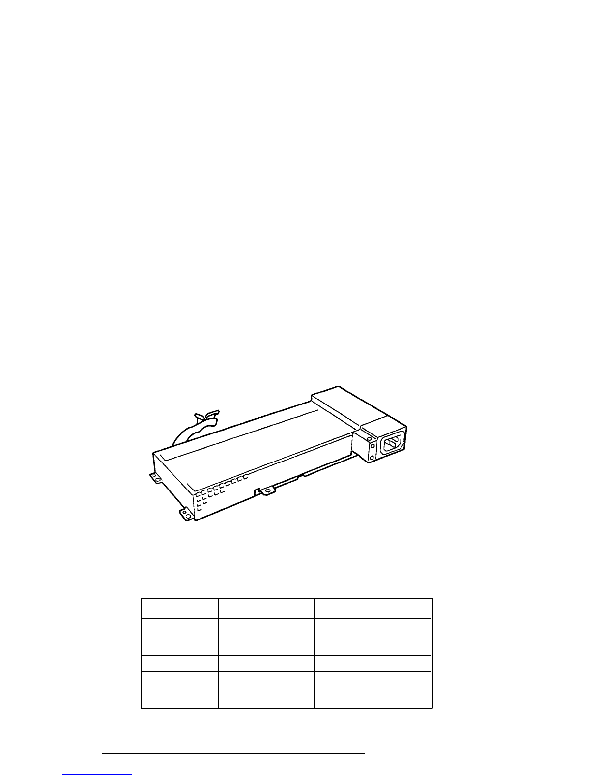
1.7 Power Supply
The universal auto-sensing power supply can be used worldwide. It supplies +5, –5, +12, +24
and –12 VDC to the system.
The power supply unit is housed in the system unit and supplies regulated power to the:
1) System board
2) Back panel board
3) 3.5-inch floppy disk drive (FDD)
4) 3.5-inch hard disk drive (HDD)
5) External keyboard port
6) Liquid crystal display (LCD)
7) Option slots
8) DC fans
9) PS/2 mouse port
The power supply unit includes an input line filter, line fuse, cooling fan, power conversion
circuitry and connectors.
Input ratings are: 115 VAC, 3.5 A or 230 VAC, 1.7 A.
The power supply unit is shown in Figure 1-8, and the output ratings are specified in Table
1-5.
Figure 1-8 Power Supply Unit
Table 1-5 Power Supply Unit Output Rating for the System
* DC Voltage (V) Maximum Current (A)
For system +5 11.8
+12 2.86
–5 0.3
–12 0.31
+24 0.5
* For identification of output voltage ratings, refer to Section C.11 in Appendix C.
T6600C, T6600C/CD, T6600C/CDV

2.1 Troubleshooting
2-1
Chapter 2 describes how to determine if a Field Replaceable Unit (FRU) in the T6600C is
causing the computer to malfunction. The FRUs covered are:
1. Power Supply
2. System Board
3. Back Panel Board
4. Floppy Disk Drive
5. Hard Disk Drive
6. Keyboard
7. Display
The Diagnostics Disk operations are described in Chapter 3 and detailed replacement procedures are given in Chapter 4.
The following tools are necessary for implementing the troubleshooting procedures:
1. A T6600C Diagnostics Disk
2. Two Phillips screwdrivers (3 mm and 2 mm)
3. A Toshiba MS-DOS system disk(s)
4. A 2DD or 2HD formatted work disk for floppy disk drive testing
5. A cleaning kit for floppy disk drive troubleshooting
6. A printer port LED
7. An RS-232-C wraparound connector
8. A printer wraparound connector
9. A multimeter
10. An external 5.25-inch floppy disk drive
11. An external CRT
12. MS-Windows V3.1 system disk
13. MS-Windows Sound system disk
14. Headphone
15. External speaker L, R (including the amplifier)
16. Microphone
17. Sound source (tape recorder, etc.)
18. Audio cable with standard 3.5 mm diameter stereo connector
19. Internal HDD (CP30544 for T6600C)
20. Internal HDD (MK-538FB)
21. External SCSI HDD
T6600C, T6600C/CD, T6600C/CDV

2-2
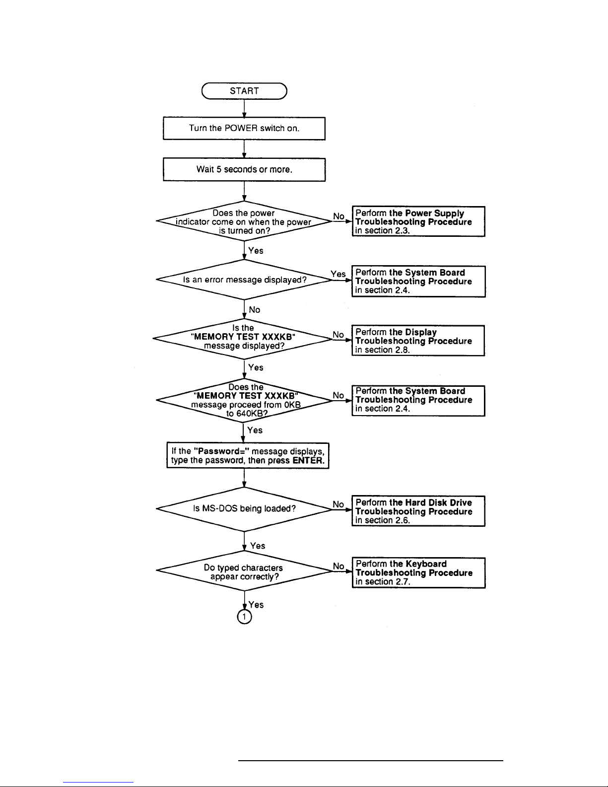
2.2 Troubleshooting Flowchart
Use the flowchart in Figure 2-1 as a guide for determining which troubleshooting procedures
to execute. Before going through the flowchart steps, verify the following:
❑ Ask the user if a password is registered, and if it is, ask him or her to enter the pass-
word. If the user has forgotten the password, refer to Appendix H for procedures on
how to delete it.
❑ Verify with the customer that Toshiba MS-DOS is installed on the hard disk. Non-
Toshiba operating systems can cause the computer to malfunction.
❑ Make sure all optional equipment is disconnected from the computer.
After removing all optional devices, if the T6600C is found to be operating properly,
then an optional device or a T6600C interface is causing the problem.
Check the following items:
For a memory card, PCMCIA card, turbo cache module, and connected I/O port
devices, check the T6600C with the optional device or with a wraparound board for
the I/O port using the test program.
If the T6600C works with no errors, the optional device is malfunctioning. If the
T6600C does not work or there is an error, the system board is malfunctioning.
For expansion slot cards, check the T6600C with a wraparound board for an expansion slot.
If the T6600C works with no errors, the expansion card is malfunctioning. If the
T6600C does not work or there is an error, the back panel board or system board is
malfunctioning.
❑ Make sure the floppy disk drive is empty.
T6600C, T6600C/CD, T6600C/CDV
2-3
Figure 2-1 Troubleshooting Flowchart (1/2)
T6600C, T6600C/CD, T6600C/CDV
2-4
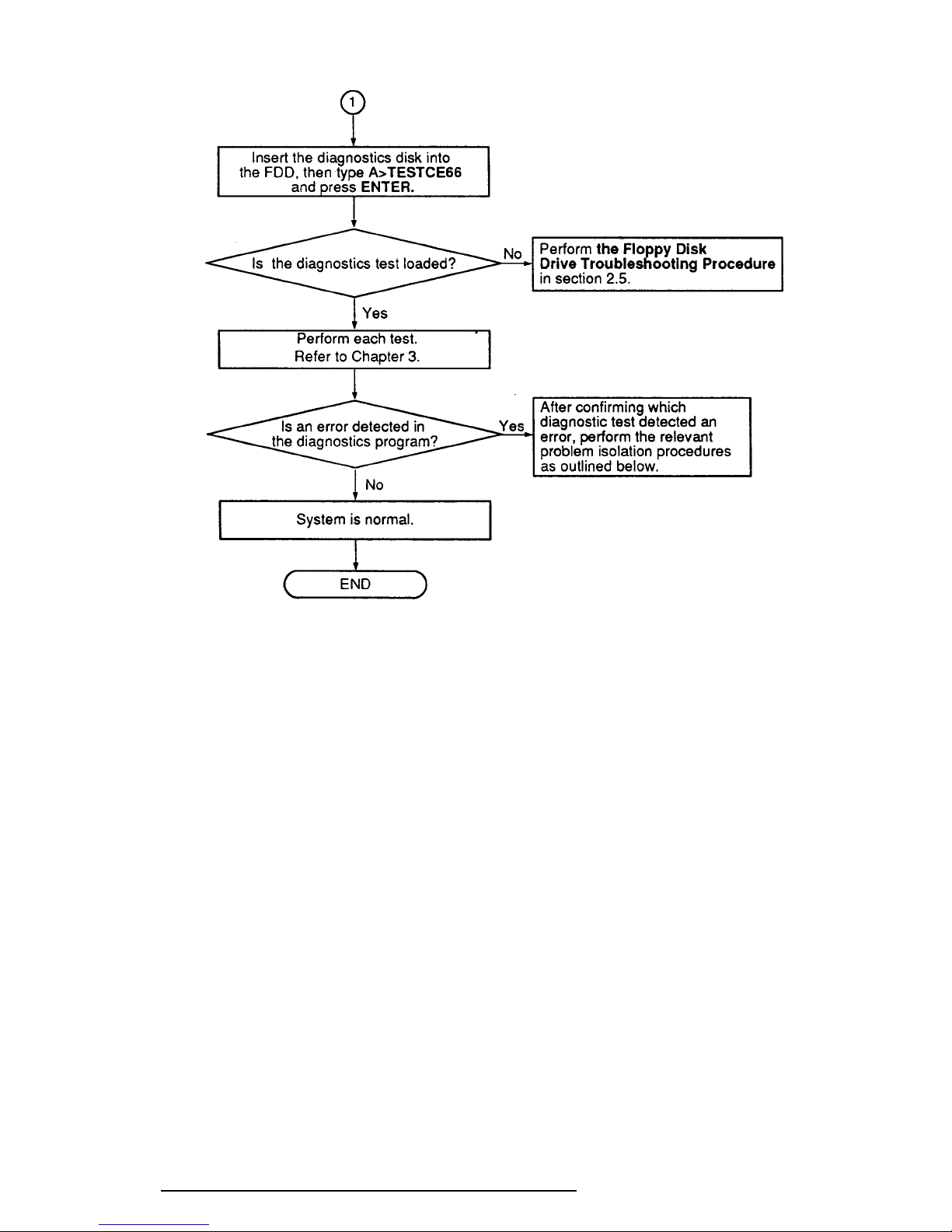
Figure 2-1 Troubleshooting Flowchart (2/2)
If the diagnostics program cannot detect an error, the problem may be intermittent. The
Running Test program should be executed several times to isolate the problem.
Check the Log Utilities function to confirm which diagnostic test detected an error(s), then
perform the appropriate troubleshooting procedures as follows:
1. If an error is detected on the System Test, Memory Test, Display Test, ASYNC
Test, Printer Test, or Real Timer Test, perform the System Board Troubleshooting
Procedures in Section 2.4.
2. If an error is detected on the Keyboard Test, perform the Keyboard Troubleshooting Procedures in Section 2.7.
3. If an error is detected on the Floppy Disk Test, perform the Floppy Disk Drive
Troubleshooting Procedures in Section 2.5.
4. If an error is detected on the Hard Disk Test, perform the Hard Disk Drive
Troubleshooting Procedures in Section 2.6.
T6600C, T6600C/CD, T6600C/CDV
2-5
2.3 Power Supply Troubleshooting
The T6600C’s power supply supplies the power to the components in the T6600C. To determine if the power supply is functioning properly, start with Procedure 1 and continue with the
other procedures as instructed. Procedures described in this section are:
Procedure 1: Power Cord Check
Procedure 2: Connector Check
Procedure 3: Output Voltage Check
Procedure 1 Power Cord Check
The T6600C’s power cord carries AC voltage to the power supply unit from a wall outlet.
Check 1 Turn off the power, make sure the power cord is firmly plugged into the AC IN
socket and into a working wall outlet. If the power cord is connected correctly,
go to Check 2.
Check 2 Disconnect the power cord from the T6600C. Use a multimeter to check the
output voltage from the wall outlet on the power cord.
If the output voltage is not correct, replace the power cord with a new one. If
output voltage is correct, perform Procedure 2.
Procedure 2 Connector Check
The power supply cables should be connected to the system board. These cables may be
disconnected or damaged. Open the keyboard cable cover following the steps described in
Chapter 4 to check the power supply cable connection to the system board.
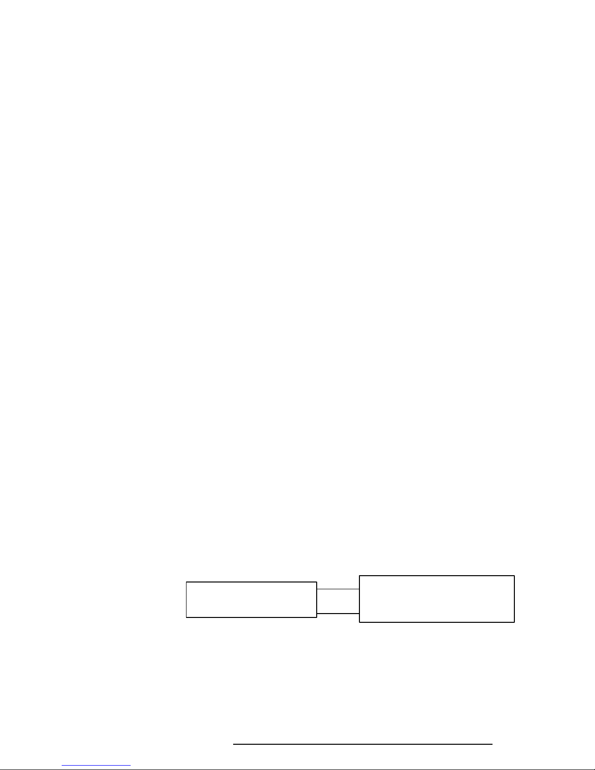
Check 1 Remove the keyboard cable cover. Make sure the power supply cables are con-
nected to the system board.
PJ440
Power supply unit System board
PJ441
If these cables are disconnected, connect them to the system board. If these cables
are damaged, replace the power supply unit.
If these cables are OK, perform Procedure 3.
T6600C, T6600C/CD, T6600C/CDV
2-6
Procedure 3 Output Voltage Checklist
The power supply supplies five voltages to the system board. Check the output voltage of the
power supply unit.
Check 1 Remove the keyboard cable cover, connect the power supply cables to the system
board, then connect the AC cord and turn on the power.
Use a multimeter to check the following voltages:
Table 2-1 Output Voltages
Connector Pin No. Voltage (V)
PJ440 1 GND
2 -5 (±10%)
3 GND
4 GND
5 GND
6 GND
7 GND
8 GND
9 GND
10 GND
11 -12 (±10%)
PJ441 1 +5 (±5%)
2 +5 (±5%)
3 +5 (±5%)
4 +5 (±5%)
5 +5 (±5%)
6 +5 (±5%)
7 +24 (+8V/-4V)
8 +12 (±5%)
9 +12 (±5%)
10 +12 (±5%)
If the output voltages are not correct, replace the power supply unit.
If the output voltages are correct, the system board may be damaged. Go to
Section 2.4, System Board Troubleshooting.
T6600C, T6600C/CD, T6600C/CDV

2-7
2.4 System Board Troubleshooting
This section describes how to determine if the system board is defective or not functioning
properly. Start with Procedure 1 and continue with the other procedures as instructed. The
procedures described in this section are:
Procedure 1: Message Check
Procedure 2: Printer Port LED Check
Procedure 3: Diagnostic Test Program Execution Check
Procedure 4: SCSI Logic Check
Procedure 5: Sound Logic Check
Procedure 6: System Board Replacement Check
T6600C, T6600C/CD, T6600C/CDV

2-8
Procedure 1 Message Check
When the power is turned on, the system performs the Initial Reliability Test (IRT) installed in
the BIOS ROM. The IRT tests each IC on the system board and initializes it.
❑ If an error message is shown on the display, perform Check 1.
❑ If there is no error message, go to Procedure 2.
❑ If Toshiba MS-DOS is properly loaded, go to Procedure 3.
Check 1 If one of the following error messages is displayed on the screen, press the F1 key
as the message instructs.
(a) *** Error in CMOS. Bad configuration type ***
Check system. Then press [F1] key ......
(b) *** Error in CMOS. Bad battery ***
Check system. Then press [F1] key ......
(c) *** Error in CMOS. Bad check sum ***
Check system. Then press [F1] key ......
(d) *** Error in CMOS. Bad memory size ***
Check system. Then press [F1] key ......
(e) *** Error in CMOS. Bad time function ***
Check system. Then press [F1] key ......
These errors occur when the system configuration preserved in the RTC memory
(CMOS-type memory) is not the same as the actual configuration or when data is
lost.
If you press the F1 key as the message instructs, the system configuration in the
RTC memory configuration is set to the default setting. If Error Message (b)
appears often when the power is turned on, replace the RTC battery. If any other
error message is displayed, perform Check 2.
Check 2 The IRT checks the system board, and when it detects an error, the system stops
or an error message appears. Refer to Table 2-2 for a list of error messages.
❑ If one of the following error messages displays, replace the system board:
Error Messages 1 through 23, 26, 30, or 31
❑ If Error Message 24 or 25 displays, go to the Keyboard Troubleshooting
Procedures in Section 2.7.
❑ If Error Message 27 or 28 is displayed, go to the HDD Troubleshooting
Procedures in Section 2.6.
❑ If Error Message 29 is displayed, go to the FDD Troubleshooting Proce-
dures in Section 2.5.
T6600C, T6600C/CD, T6600C/CDV
2-9
Table 2-2 IRT Error Messages
No. Error Message
1 CPU ERROR
2 SYSTEM BIOS CHECK SUM ERROR
3 TIMER CH.2 OUT ERROR
4 PIT ERROR
5 MEMORY REFRESH ERROR
6 FIRST 64KB MEMORY ERROR
7 FIRST 64KB MEMORY PARITY ERROR
8 RTC ERROR
9 RTC UPDATE ERROR
10 CRTC ERROR
11 VRAM ERROR
12 KBC ERROR
13 SYSTEM MEMORY ERROR
14 SYSTEM MEMORY PARITY ERROR
15 EXTENDED MEMORY ERROR
16 EXTENDED MEMORY PARITY ERROR
17 PROTECTED MODE ERROR
18 CPU EXCEPTION ERROR
19 DMA PAGE REGISTER ERROR
20 DMAC #1 ERROR
21 DMAC #2 ERROR
22 PIC #1 ERROR
23 PIC #2 ERROR
24 KEYBOARD ERROR
25 KBC ERROR
26 HDC ERROR
27 HDD #0 ERROR
28 HDD #1 ERROR
29 NO FDD ERROR
30 FDC ERROR
31 TIMER INTERRUPT ERROR
T6600C, T6600C/CD, T6600C/CDV
2-10
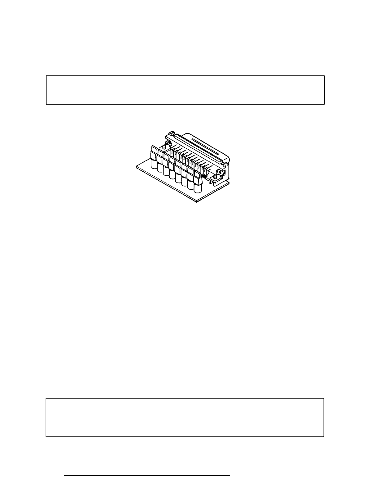
Procedure 2 Printer Port LED Check
The printer port LED displays the IRT status and test status by turning lights on and off as an
eight-digit binary value. Figure 2-2 shows the printer port LED.
NOTE: When you perform this check, the external FDD/PRT option in the SETUP
program must be set to PRT.
Figure 2-2 Printer Port LED
To use the printer port LED, follow these steps:
1. Turn off the T6600C’s power.
2. Plug the printer port LED into the computer’s PRT/FDD connector.
3. Hold down the space bar and turn on the T6600C’s power.
4. Read the LED status from left to right as you face the back of the computer.
5. Convert the status from binary to hexadecimal notation.
6. If the final LED status is FFh (normal status), go to Procedure 3.
7. If the final LED status matches any of the test status values in Table 2-3, perform
Check 1.
NOTE: If an error condition is detected by the IRT test, the printer port LED displays
an error code. For example, if the printer port LED displays 02H and halts, it indicates a PIT test error.
T6600C, T6600C/CD, T6600C/CDV
2-11
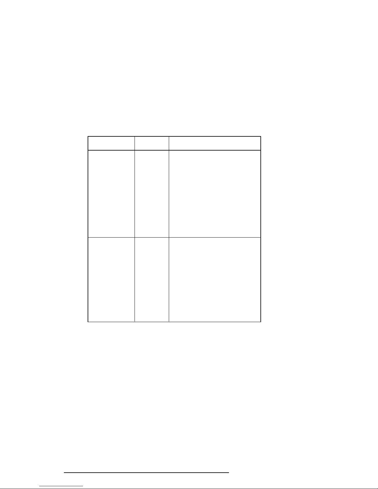
Table 2-3 Printer Port LED Boot Mode Error Statuses (1/2)
Error Status Test Item Message
01H CPU test CPU ERROR
System ROM
check sum test SYSTEM ROM CHECK SUM ERROR
02H PIT test TIMER CH.2 OUT ERROR
PIT ERROR
READ DATA = XXH
WRITE DATA = XXH
05H PIT initialization —
06H PIT function test MEMORY REFRESH ERROR
07H First 64KB memory test FIRST 64KB MEMORY ERROR
FIRST 64KB MEMORY PARITY ERROR
0AH System memory —
initialization
0CH Interrupt vector —
initialization
0DH RTC test RTC ERROR
READ DATA = XXH
WRITE DATA = XXH
RTC UPDATE ERROR
15H RTC initialization
16H PIC initialization
18H Display initialization CRTC ERROR
VRAM ERROR
READ DATA = XXXXXXXXH
WRITE DATA = XXXXXXXXH
1FH KBC test KBC ERROR
22H System memory test SYSTEM MEMORY ERROR
ADDRESS = XXXXXXXXH
READ DATA = XXXXXXXXH
WRITE DATA = XXXXXXXXH
SYSTEM MEMORY PARITY ERROR
ADDRESS = XXXX0000H - XXXXFFFFH
25H Extended memory test EXTENDED MEMORY ERROR
ADDRESS = XXXXXXXXH
READ DATA = XXXXXXXXH
WRITE DATA = XXXXXXXXH
EXTENDED MEMORY PARITY ERROR
ADDRESS = XXXX0000H - XXXXFFFFH
30H PROTECTED MODE ERROR
31H CPU EXCEPTION ERROR
33H DMA page register test DMA PAGE REGISTER ERROR
T6600C, T6600C/CD, T6600C/CDV
READ DATA = XXH
WRITE DATA = XXH
2-12
Table 2-3 Printer Port LED Boot Mode Error Statuses (2/2)
Error Status Test Item Message
40H DMAC test DMAC #1 ERROR
READ DATA = XXXXH
WRITE DATA = XXXXH
DMAC #2 ERROR
READ DATA = XXXXH
WRITE DATA = XXXXH
41H DMAC initialization 42H PIC test PIC #1 ERROR
READ DATA = XXH
WRITE DATA = XXH
PIC #2 ERROR
READ DATA = XXH
WRITE DATA = XXH
4AH Keyboard test KEYBOARD ERROR
54H KBC initialization KBC ERROR
55H Mouse initialization 5BH Password check
5DH HDD initialization HDC ERROR
HDC #0 ERROR
HDC #1 ERROR
60H FDD initialization NO FDD ERROR
FDD ERROR
65H Printer test -
70H SIO test -
80H Timer initialization TIMER INTERRUPT ERROR
RTC UPDATE ERROR
90H NDP initialization A0H Expansion I/O ROM A6H Others H/W initialization FEH Expansion system ROM -
FFH CMOS RAM test ****Error in CMOS. Bad battery****
****Error in CMOS. Bad check sum****
****Error in CMOS. Bad configuration****
****Error in CMOS. Bad time function****
Check system. Then press [F1] key
T6600C, T6600C/CD, T6600C/CDV

2-13
Check 1 If any of the following error codes are displayed, replace the system board with a
new one.
00h, 02h, 05h, 06h, 07h, 0Ah, 0Ch, 0Dh, 15h, 16h, 18h, 1Fh, 22h, 25h, 30h, 31h,
33h, 40h, 41h, 42h, 54h, 55h, 5Bh, 60h, 65h, 70h, 80h, 90h, A0h, A6h, FEh
Check 2 If Error Code 4Ah is displayed, go to the Keyboard Troubleshooting procedures
in Section 2.7.
Check 3 If Error Code 5Dh is displayed, go to the HDD Troubleshooting procedures in
Section 2.6.
Check 4 If Error Code 60h is displayed, go to the FDD Troubleshooting procedures in
Section 2.5.
Procedure 3 Diagnostic Test Program Execution Check
Execute the following tests from the Diagnostic Test Menu. Refer to Chapter 3, Tests and
Diagnostics, for more information on how to perform these tests.
1. System Test
2. Memory Test
3. Printer Test
4. ASYNC Test
If an error is detected during these tests, replace the system board with a new one.
T6600C, T6600C/CD, T6600C/CDV

2-14
Procedure 4 SCSI Logic Check
Execute the following tests from the Diagnostic Test Menu. Refer to Chapter 3, Tests and
Diagnostics, for more information on how to perform these tests.
Check 1 External SCSI interface check
Step 1 Make sure the internal SCSI connector is not connected to PJ9 on the
back panel board.
Step 2 Connect the SCSI terminator resister module to the RM 101 and RM
102 sockets on the back panel board.
Step 3 Make sure the RM 1 and RM 2 sockets are not connected to the
system board.
Step 4 Connect the external SCSI HDD to the external SCSI port (PJ680).
Step 5 Execute the HDD test of the diagnostic test program. Select 2: HDD2
for the Test drive number.
If an error is detected during the HDD tests, replace the system board
with a new one.
Check 2 Internal SCSI interface check
Step 1 Make sure the external SCSI port is not connected to PJ680 on the
system board.
Step 2 Connect the internal SCSI HDD to PJ9 on the back panel board and
SCSI HDD power cable to PJ6 or PJ7.
Step 3 Make sure RM 101 and RM 102 are not connected.
Step 4 Connect the SCSI terminator resister module to RM 1 and RM 2 on
the system board.
Step 5 Execute the HDD test in the diagnostic test program. Select 2:HDD2
for the Test drive number.
If an error is detected during the HDD tests, replace the system board
with a new one.
T6600C, T6600C/CD, T6600C/CDV

2-15
Procedure 5 Sound Logic Check
Follow these procedures to execute the sound controller test with a sound source, such as a
tape recorder. You will need to connect a mouse to execute this test.
Preparation of a Spare HDD
Step 1 Install Toshiba MS-DOS, Windows 3.1, Windows Sound System, and the
Logitech Trackman Portable Driver.
Step 2 Open the Windows file "WIN.INI" in a text editor.
Step 3 Edit the following lines under [windows] in the WIN.INI file in the order
indicated below:
load=C:\SNDSYS\QRECORD.EXE (about line five of the file)
run=C:\SNDSYS\SOUNDS\POPJAZ30.RMI (about line 90 of the
file)
Step 4 Insert the following lines under [sounds] in the WIN.INI file in the order
indicated below:
SystemStart=C:\SNDSYS\SOUNDS\WAGNER.WAV,Windows
Start
Step 5 Edit the AUTOEXEC.BAT file as follows:
rem c:\DOS\DOSSHELL (change)
WIN (add as the last line)
Preparation for the Test
Step 1 Remove any SCSI devices that may be connected. (Be sure to reinstall
them after completing the test.)
Step 2 Install the HDD prepared for conducting the sound system test. (After the
test, reinstall the original HDD.)
Step 3 Connect a Logitech Trackman Portable to the connector panel.
Step 4 Connect the following to the connector panel: mike to PJ360, speaker with
amplifier to PJ370, and sound source to PJ361.
T6600C, T6600C/CD, T6600C/CDV

2-16
Test Execution
Remove any floppy disk from the FDD and turn on the power. Follow the steps below
to execute the sound controller test:
Step 1 Confirm that Wagner’s Wedding March is played when power is turned on.
Step 2 Confirm that pops and jazz are played.
Step 3 While the music is playing, plug a headphone into jack PJ381 and confirm
Step 4 Before pops and jazz stop automatically, press Alt + S to halt sound
Step 5 Put on the headphones.
Step 6 Use the mouse to double click the Quick Recorder icon at the bottom left
Step 7 Click the red circle in the window and say “test, test” into the mike to
that sound from the speakers is turned off.
execution.
of the screen to display the Quick Recorder window.
record your voice.
Step 8 Click the black square to stop recording.
Step 9 Click the black triangle to check that your voice is played back.
Step 10 Click the black square and select Options.
Step 11 Select Set Recording Level.
Step 12 Select Line-in.
Step 13 Turn on the sound source.
Step 14 Click the Red circle to record the sound source.
Step 15 Click the black square to stop recording.
Step 16 Click the black triangle to check that the sound source is played back.
Step 17 Click the black square.
Step 18 Select Options.
Step 19 Select Set Recording Level.
Step 20 Select microphone.
T6600C, T6600C/CD, T6600C/CDV
 Loading...