

Toshiba T6400 Maintenance Manual

Chapter 1
Hardware Overview
1-1

This page intentionally left blank
1-2

Contents
1.1 General................................................................................................................................1-5
1.2 System Unit Block Diagram................................................................................................ 1-8
1.3 3.5-inch Floppy Disk Drive ............................................................................................... 1-10
1.4 3.5-inch Hard Disk Drive .................................................................................................. 1-11
1.5 Keyboard........................................................................................................................... 1-12
1.6 Gas Plasma Display ........................................................................................................... 1-13
1.7 Color Liquid Crystal Display ............................................................................................ 1-14
1.8 Power Supply Unit ............................................................................................................ 1-15
Tables
Table 1-1 T6400 models ........................................................................................................... 1-5
Table 1-2 3.5-inch FDD specifications .................................................................................... 1-10
Table 1-3 3.5-inch HDD specifications ................................................................................... 1-11
Table 1-4 Gas plasma display specifications ........................................................................... 1-13
Table 1-5 Color LCD specifications........................................................................................ 1-14
Table 1-6 Power supply unit output ratings............................................................................. 1-15
Figures
Figure 1-1 T6400 system unit..................................................................................................... 1-7
Figure 1-2 Block diagram ........................................................................................................... 1-8
Figure 1-3 3.5-inch FDD .......................................................................................................... 1-10
Figure 1-4 3.5-inch HDD..........................................................................................................1-11
Figure 1-5 Keyboard................................................................................................................. 1-12
Figure 1-6 Gas plasma display ................................................................................................. 1-13
Figure 1-7 Color LCD .............................................................................................................. 1-14
Figure 1-8 Power supply unit ................................................................................................... 1-15
1-3

This page intentionally left blank
1-4

UPDATE
1.1 General
The Toshiba T6400 is one of the lightest and most advanced portable computers available. Utilizing advanced technology and high speed components, the T6400 offers excellent display legibility
and IBM PC/AT compatibility.
There are four models of the T6400 depending on the CPU, display type, and HDD capacity. Refer
to Table 1-1 below.
Table 1-1 T6400 models
CPU Display Type HDD capacity (MB)
PDP 200
Intel
80486DX-33
TFT 200
PDP 120
Intel
80486SX-25
TFT 120
The T6400 system unit consists of the following features:
Microprocessor The T6400 model uses an 80486SX-25 microprocessor that operates at 25
MHz.
The T6400DX model uses an 80486DX-33 microprocessor that operates at
33 MHz.
Math co-processor The T6400DX model has a Numeric Data Processor (NDP) inside the CPU.
The T6400 comes with a built-in socket for an 80486DX-33 which incorporates a Numeric Data Processing Unit (NDP).
Cache memory The T6400 has an 8 KB cache memory which is stored in the microproces-
sor.
Disk storage The T6400 has an internal 120 or 200 Megabyte (MB) Hard Disk Drive
(HDD) with an average access time of 19 milliseconds. A 3.5-inch Floppy
Disk Drive (FDD) supports 2HD floppy disks (1.44 Mbytes) and 2DD
floppy disks (720 Kbytes).
1-5

Memory The T6400 comes standard with 4 MB of CMOS Random Access Memory
(RAM). This includes 640 KB of conventional memory and 3456 KB of
extended memory which can be utilized as expanded memory compatible
with the Lotus/Intel/Microsoft Expanded Memory Specifications (LIMEMS).
Display The T6400 has two types of internal displays. They are an active matrix
Thin Film Transistor (TFT) type color Liquid Crystal Display (LCD)
640x480 pixels, and a high resolution Plasma Display (PDP) 640x480
pixels with a 16-level gray scale.
The T6400 internal display controller supports Video Graphics Adapter
(VGA) functions on the internal display devices.
Keyboard The detachable easy-to-use 101/102-key keyboard with full size keys and
standard spacing is compatible with IBM standard software.
Power supply The universal auto-sensing power supply enables world-wide usage of the
T6400 as long as a compatible AC plug is available.
Battery The one Real Time Clock (RTC) battery keeps the date and time in addi-
tion to the system configuration parameters even if the system is powered
off.
Expansion slot The T6400 expansion slot is used to enhance the T6400 capabilities with
various ISA adapter cards, which fit in one 8-bit or 16-bit full-size industry
standard slot.
Parallel port A Centronics-compatible parallel interface port serves two purposes. The
port can be used to connect a Centronics-compatible printer or an external
floppy disk drive.
RS-232-C port The T6400 has one 9-pin serial interface port.
Keyboard port The T6400 has an external PS/2 keyboard interface port on the right side.
Mouse port The T6400 has one 6-pin mouse port on the back that can be used for
connecting a PS/2 mouse.
RGB port The T6400 has one 15-pin RGB port on the back that can be used for
connecting an external video display.
Ext. 3.5" FDD port The 26-pin FDD interface port allows you to connect the optional Toshiba
external 3.5" FDD unit.
Built-in modem port A Toshiba built-in modem can be installed inside the T6400.
1-6

Expansion port The 150-pin expansion bus connector port allows you to connect unique
optional Toshiba devices.
Memory slots The T6400 has two expansion memory slots for installing the optional 2, 4,
and/or 8 MByte memory cards.
The T6400 Personal Computer is shown in Figure 1-1.
Figure 1-1 T6400 system unit
1-7

1.2 System Unit Block Diagram
Figure 1-2 is a block diagram of the T6400 system unit.
1-8
Figure 1-2 Block diagram

The T6400 system board shown in Figure 1-2 is composed of the following major components:
❑ An 80486DX-33 or 80486SX-25 CPU
❑ Super Integration (SI) T9901 (208-pin), which stores the following components:
●
Two Direct Memory Access Controllers (DMACs): 82C37
●
Two Programmable Interrupt Controllers (PICs): 82C59
●
One Programmable Interval Timer (PIT): 82C54
●
One Floppy Disk Controller (FDC): TC8565
●
One Serial Input/Output controller (SIO): TC8570
●
One Variable Frequency Oscillator (VFO): TC8568
●
One I/O Controller
❑ A Real Time Clock (RTC): 146818AF
❑ A Keyboard Controller (KBC): 80C42
❑ Memory:
Standard RAM: 4 MB
Cache memory: 8 KB (inside CPU)
BIOS ROM: 1 MB
This ROM contains the Initial Reliability Test (IRT), Basic Input/Output
System (BIOS), and video BIOS.
Video RAM: 256 KB
Optional memory cards expand memory to a maximum of 20 MB.
❑ System controller gate array: SYS CNT-GA (240-pin)
❑ VGA display controller: PVGA1F: WD90C23 (132-pin)
❑ Color gray scale controller
gate array: CGSC-GA (60-pin)
❑ Digital analog converter: DAC (80-pin)
❑ The following Oscillators (OSC):
X1: 33.34 MHz or 25.0 MHz OSC is used for the CPU
X5: 14.31818 MHz OSC is used for the KBC
X6: 14.7456 MHz OSC is used for the SIO
X7: 24 MHz OSC is used for the FDC and VFO
X9: 44.9 MHz OSC is used for the display controller
X901: 28.322 MHz OSC is used for the display controller
X902: 25.175 MHz OSC is used for the display controller
X903: 32.768 KHz OSC is used for the RTC
X904: 36.0 MHz OSC is used for the display controller
1-9
1.3 3.5-inch Floppy Disk Drive
Recording method Modified Frequency Modulation (MFM)
The T6400 3.5-inch Floppy Disk Drive (FDD) is a thin, high-performance, reliable drive that
supports 720KB (formatted) 2DD and 1.44MB (formatted) 2HD 3.5-inch floppy disks.
The T6400 FDD is shown in Figure 1-3 and its specifications are described in Table 1-2.
Figure 1-3 3.5-inch FDD
Ite m 2-Mbyte mode 1-Mbyte mode
Storage capacity (Kbyte)
Unformatted
Formatte d
Number of heads 2 2
Number of cylinders 80 80
Access time (ms)
Track to trac k
Average
Head settling time
Recording trac k density (tpi) 135 135
Data transfer rate (Kbps) 500 250
Rotation speed (rpm) 300 300
2,000
1,475
3
94
15
1,000
737
3
94
15
1-10
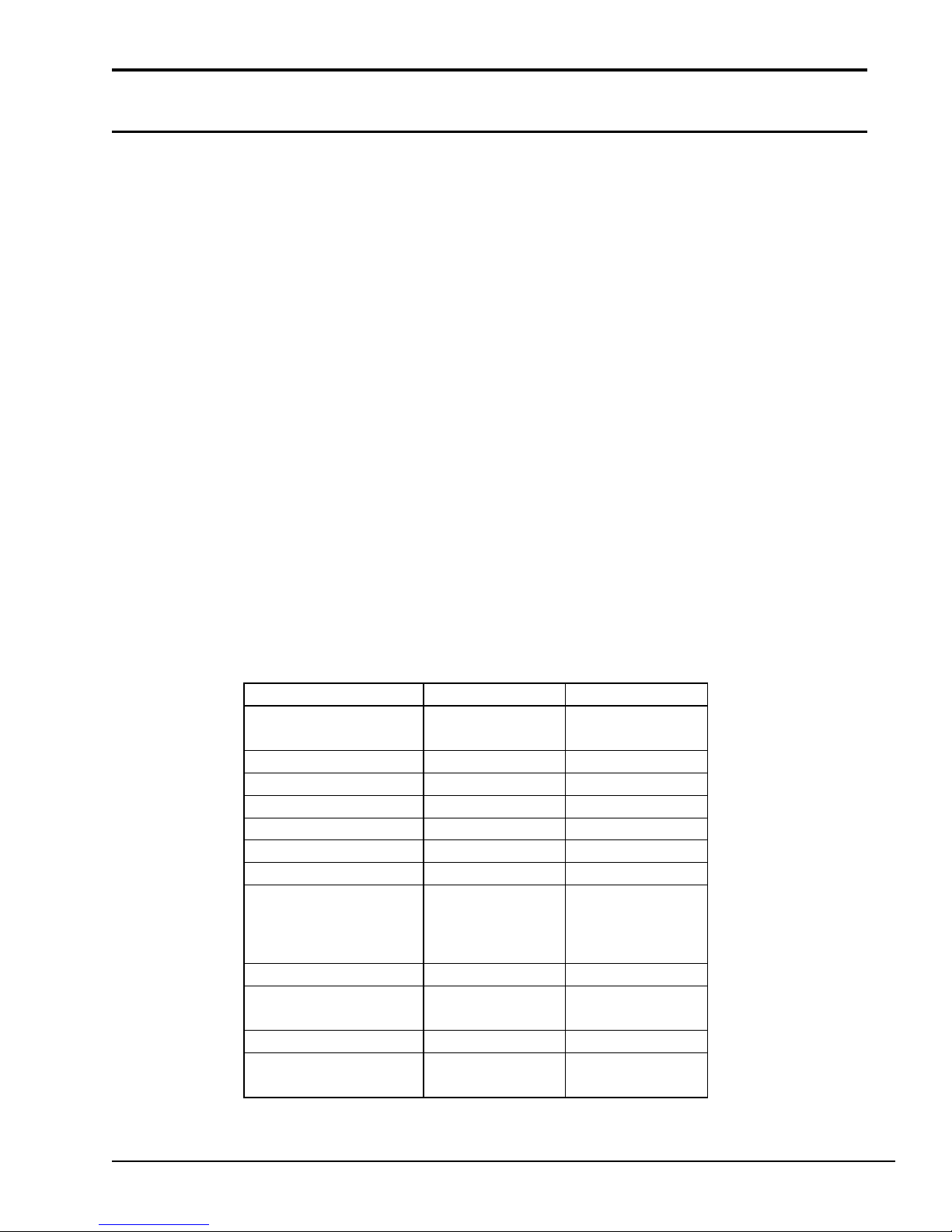
Table 1-2 3.5-inch FDD specifications
-7
-7
1.4 3.5-inch Hard Disk Drive
The T6400 120MB or 200MB (formatted) Hard Disk Drive (HDD) is a random access, non-volatile
storage device. It has a non-removable 3.5-inch magnetic disk and mini-Winchester type magnetic
heads.
The T6400 HDD is shown in Figure 1-4. Specifications for the HDD are described in Table 1-3.
Figure 1-4 3.5-inch HDD
Item 200MB ( CP-30204) 120MB ( CP-30104)
Storage capacity
For matted (MB)
Nu mber of disks 2 2
Data head s 4 4
Data surfaces 4 4
Tracks per sur fa ce 2,119 1,522
Sectors per track 4 9 39 (+1)
Bytes per sector 512 512
Access time (m s)
T rack to track
Averag e
Maximum
Rotation speed ( rpm) 4,498 3,400
Data transfer r ate (MB/S)
To/from media
Inter leave 1:1 1:1
Recording m ethod
212 .6 121.5
3
1 2
3 0
2.5 M 1.5M
2-7 RL L/
1
RL L
2-7 RL L/
1
8
1 9
4 0
RL L
1-11

Table 1-3 3.5-inch HDD specifications
1.5 Keyboard
The 101-key (USA) or 102-key (European) keyboard is mounted on the T6400’s system unit. The
keyboard is connected to the keyboard controller in the keyboard unit. The keyboard is shown in
Figure 1-5.
See Appendix E for optional keyboard configurations.
Figure 1-5 Keyboard
1-12
1.6 Gas Plasma Display
Mea n time between failure (MTBF) (hours) 20,000
The gas plasma display is composed of a display panel and driver circuits. It receives vertical and
horizontal synchronizing signals, four-bit data signals, and shift clock for data transmission. All
signals are TTL-level compatible. The display has 16 levels of gray scale and the display quality
can be adjusted with the contrast control.
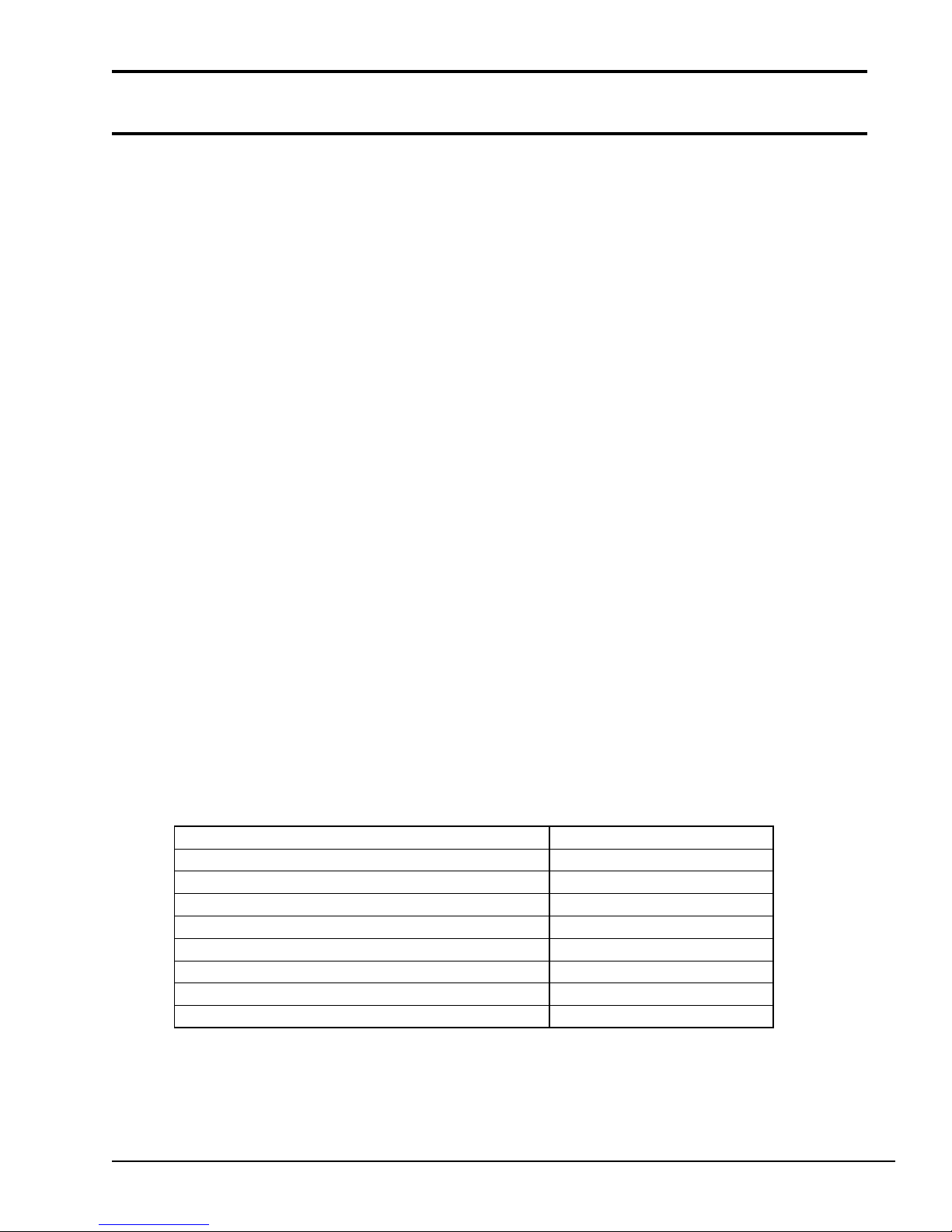
The gas plasma display is shown in Figure 1-6 and its specifications are described in Table 1-4.
Figure 1-6 Gas plasma display
Item Specifications
Numbe r of dots (dots) 640 x 480
Dot pitc h (mm) 0.33 (W) x 0.33 (H)
Display are a (mm) 158.4 (W) x 211.2 (H)
Color Neon-Orange
Contrast ratio 100:1
Gray scale 16 levels
Power (maximum) 20 watts
1-13
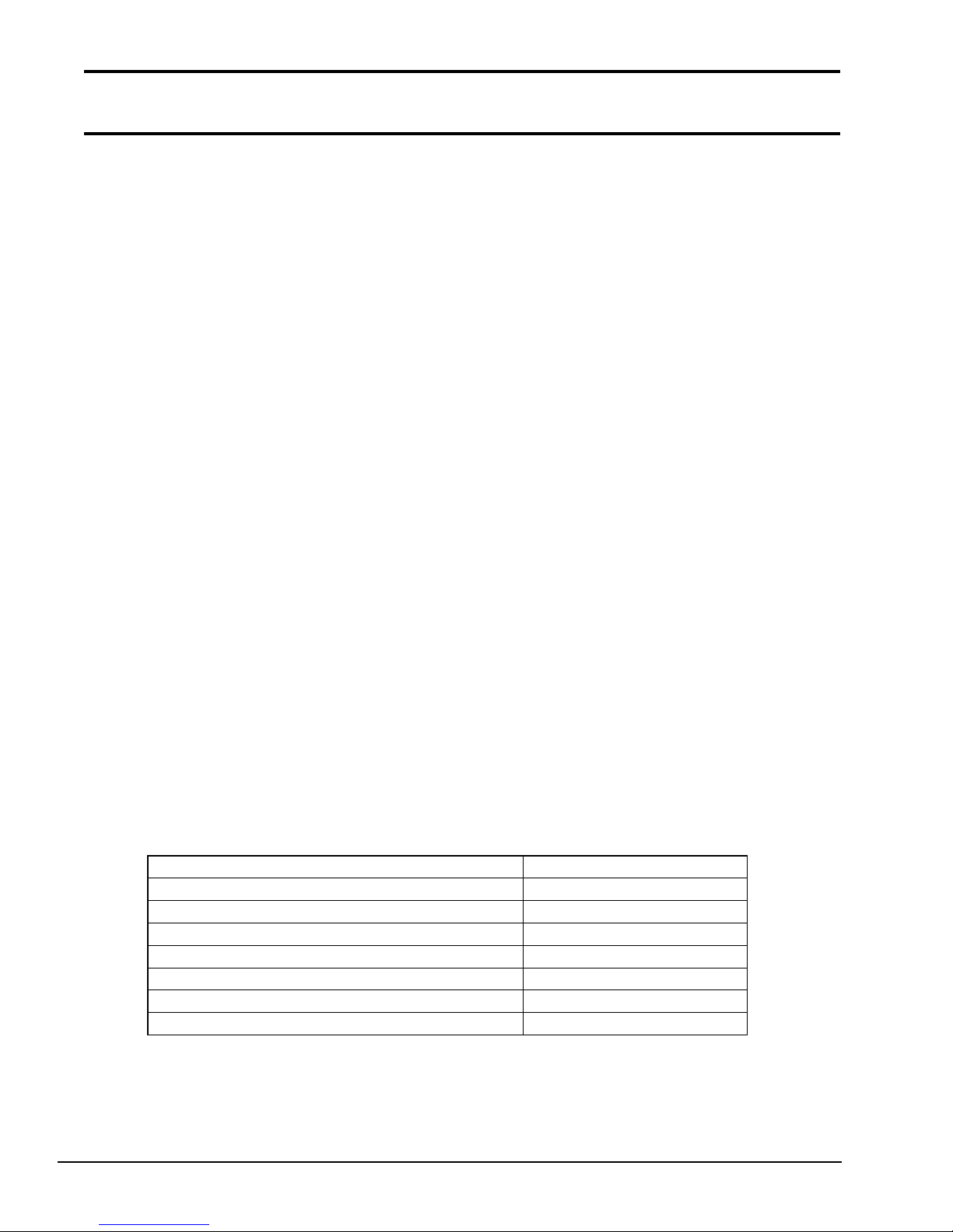
Table 1-4 Gas plasma display specifications
Power (maximum) 19 watts
1.7 Color Liquid Crystal Display
The color liquid crystal display (LCD) is composed of an LCD module, fluorescent lamps (FLs),
and an FL inverter board. The thin film transistor (TFT) LCD is illuminated from the back. Thus,
you can read its display clearly even in poorly lit conditions. It receives vertical and horizontal
synchronizing signals, 9-bit data signals, and shift clock signals for data transmission. All signals
are TTL-level compatible. The LCD specifications are described in Table 1-5.
The LCD has 512-color capability. The high frequency current is supplied by the FL inverter board
to illuminate the FLs. The color LCD is shown in Figure 1-7.
1-14
Figure 1-7 Color LCD
Item Specifications
Numbe r of dots (dots) 640 x 480
Dot pitc h (mm) 0.33 (W) x 0.33 (H)
Display are a (mm) 211.2 (W) x 158.4 (H)
Color 512 colors
Contrast ratio 60:1
Gray scale 8 leve ls for each gun (RGB)

Table 1-5 Color LCD specifications
+24 20 (17)
1.8 Power Supply Unit
The universal auto-sensing power supply can be used world-wide and supplies +5, -5, +12, and -12
VDC to the system.
The power supply unit is housed in the system unit and it supplies regulated power to the:
●
System board
●
Memory board
●
3.5-inch floppy disk drive (FDD)
●
3.5-inch hard disk drive (HDD)
●
External keyboard
●
Liquid crystal display (LCD) or plasma display (PDP)
●
Option boards
●
Cooling fans
The power supply unit includes an input line filter, line fuse, cooling fans, power conversion
circuitry, and connectors.
Input ratings are: 115 VAC, 1.5 A or 230 VAC, 1.0 A
The power supply unit is shown in Figure 1-8 and the output ratings are specified in Table 1-6.
Figure 1-8 Power supply unit
DC voltage (V) Maximum current (A)
+5 6.09
+12 0.9 (1.32)
For system
-5 0.15
-12 0.25
Table 1-6 Power supply unit output ratings
1-15

This page intentionally left blank
1-16

Chapter 2
Troubleshooting Procedures
2-1

This page intentionally left blank
2-2

Contents
2.1 T6400 Troubleshooting........................................................................................................2-5
2.2 Troubleshooting Flowchart ..................................................................................................2-6
2.3 Power Supply Unit Troubleshooting Procedures .................................................................. 2-8
Procedure 1 AC Cord Check..............................................................................................2-9
Procedure 2 Connector Check ......................................................................................... 2-10
Procedure 3 Output Voltage Check ................................................................................. 2-11
2.4 System Board Troubleshooting Procedures........................................................................2-12
Procedure 1 Message Check ............................................................................................ 2-13
Procedure 2 Printer Port LED Check...............................................................................2-15
Procedure 3 Diagnostic Test Program Execution Check.................................................. 2-19
2.5 Floppy Disk Drive Troubleshooting Procedures................................................................. 2-20
Procedure 1 FDD Head Cleaning Check..........................................................................2-21
Procedure 2 External 5-1/4" FDD Check.........................................................................2-22
Procedure 3 Diagnostic Test Program Execution Check.................................................. 2-23
Procedure 4 Connector and Replacement Check ............................................................. 2-24
2.6 Hard Disk Drive Troubleshooting Procedures .................................................................... 2-25
Procedure 1 Message Check ............................................................................................ 2-26
Procedure 2 Partition Check ............................................................................................ 2-27
Procedure 3 Format Check .............................................................................................. 2-28
Procedure 4 Diagnostic Test Program Execution and Replacement Check...................... 2-29
2.7 Keyboard Troubleshooting Procedures .............................................................................. 2-30
Procedure 1 Diagnostic Test Program Execution Check.................................................. 2-31
Procedure 2 Connector and Replacement Check ............................................................. 2-32
2.8 Display Troubleshooting Procedures ................................................................................. 2-33
Procedure 1 Brightness Volume Check (for Plasma Type)..............................................2-34
Procedure 2 External CRT Check....................................................................................2-35
Procedure 3 Diagnostic Test Program Execution Check.................................................. 2-36
Procedure 4 Connector Check ......................................................................................... 2-37
Procedure 5 Replacement Check ..................................................................................... 2-38
Tables
Table 2-1 Output voltages ........................................................................................................ 2-11
Table 2-2 Printer port LED test status ...................................................................................... 2-16
Table 2-3 Floppy disk drive error codes and status .................................................................. 2-23
Table 2-4 Hard disk drive error codes and statuses .................................................................. 2-28
Figures
Figure 2-1 Troubleshooting flowchart .........................................................................................2-6
Figure 2-2 Printer port LED ...................................................................................................... 2-15
2-3

This page intentionally left blank
2-4

2.1 T6400 Troubleshooting
Chapter 2 describes how to determine if a Field Replaceable Unit (FRU) in the T6400 is causing
the computer to malfunction. The FRUs covered are:
1. Power supply unit
2. System board
3. Floppy Disk Drive
3. Hard Disk Drive
4. Keyboard
5. Display
The following tools will assist you in performing the T6400 troubleshooting procedures.
1. T6400 Diagnostic Disk
2. Phillips head screwdriver (2 mm)
3. Toshiba MS-DOS system disk
4. 2DD or 2HD formatted work disk for the floppy disk drive troubleshooting
5. Cleaning disk kit for the floppy disk drive troubleshooting
6. Printer port LED
7. RS-232-C wraparound connector
8. Printer wraparound connector
9. Expansion slot wraparound board (F32BUS)
10. Multimeter
11. External 5.25" and 3.5" floppy disk drives
12. External CRT
13. External keyboard
14. PS/2 mouse and driver software
2-5
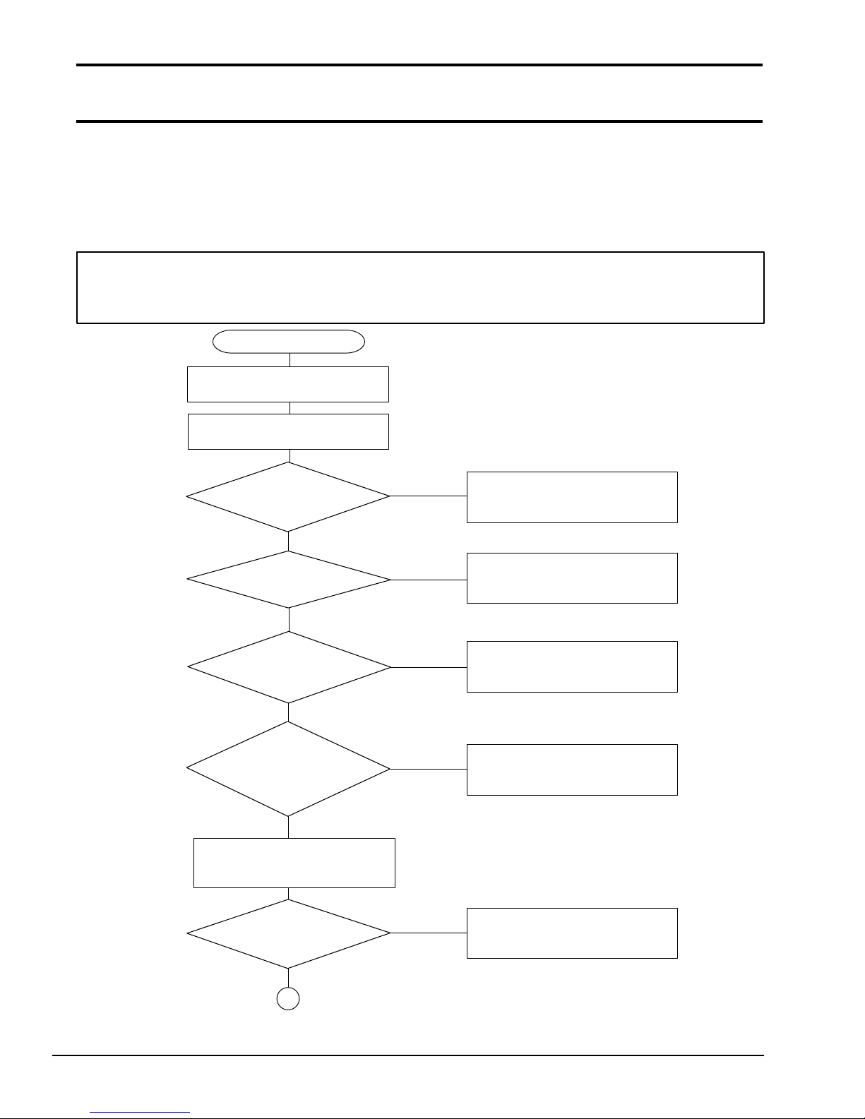
2.2 Troubleshooting Flowchart
Use the flowchart in Figure 2-1 as a guide to determine which FRU troubleshooting procedures to
execute. Before performing the flowchart procedures, perform the following:
❑ Disconnect all optional equipment from the T6400.
❑ Remove any diskette in the FDD.
NOTE: If you forget the password and cannot start up the computer, connect the printer
port wraparound board (F31PRT), then turn the POWER switch on. The computer will skip
the password function.
START
Insert the Toshiba MS-DOS diskette
into the FDD.
Turn the Power Switch ON
and wait 5 seconds.
Does the
POWER INDICATOR
illuminate?
YES
Is an
Error Message
displayed?
NONO
Is the
MEMORY TEST XXXXKB
message displayed
?
YES
Does the
MEMORY TEST XXXKB
message proceed from
0KB to 640KB?
YES
If the Password = prompt is
displayed, type in the user password
and press Enter.
NO
YES
NO
NO
Perform Power Supply Board
Troubleshooting Procedures in
Section 2.3.
Perform System Board
Troubleshooting Procedures in
Section 2.4.
Perform Display Troubleshooting
Procedures in Section 2.8.
Perform System Board
Troubleshooting Procedures in
Section 2.4.
Is Toshiba
MS-DOS being
loaded?
1
Figure 2-1 Troubleshooting flowchart
2-6
YES
NO
Perform Floppy Disk Drive
Troubleshooting Procedures in
Section 2.5.
1
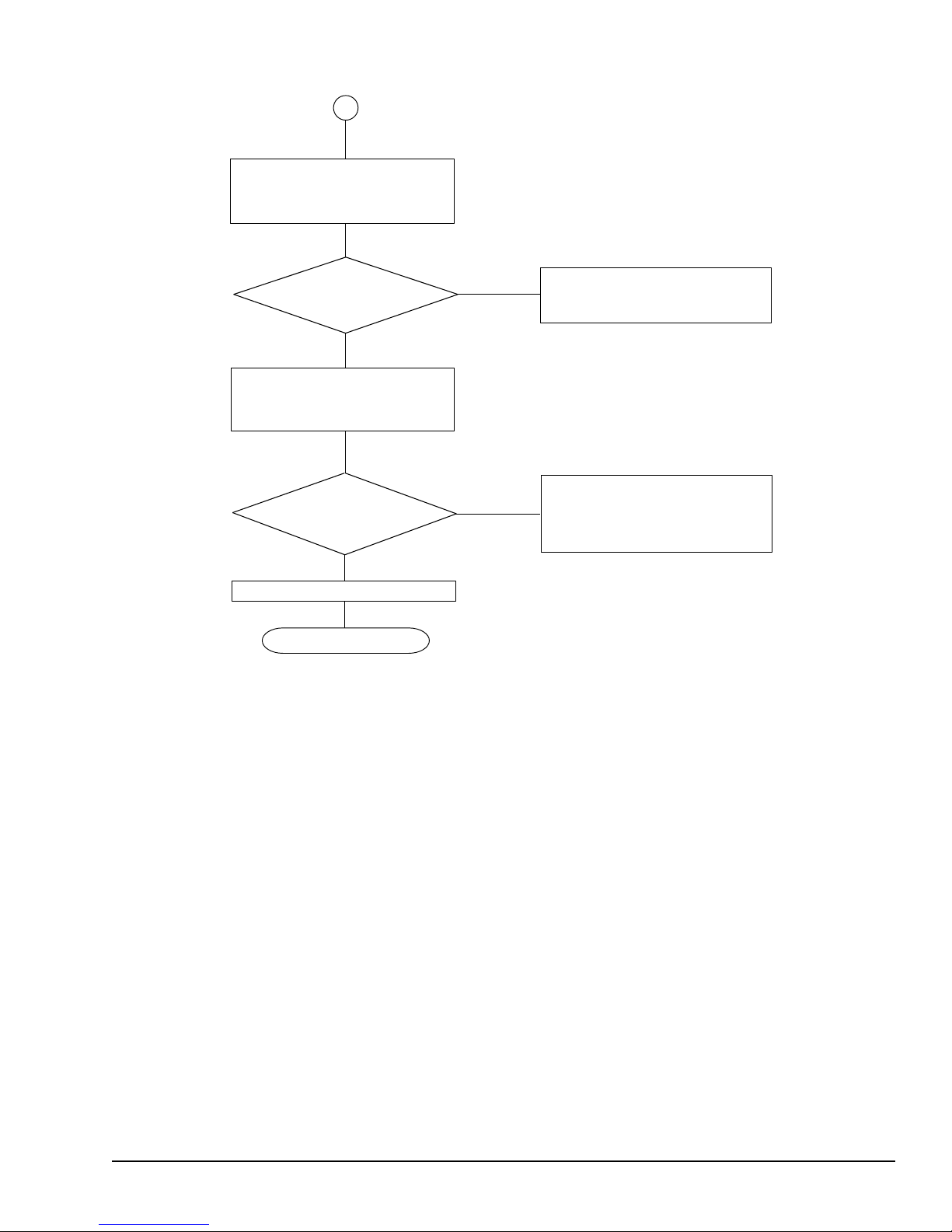
Insert the ASP Diagnostics diskette
into the FDD, type A:TESTCE64,
and press ENTER.
Do typed
characters appear
correctly?
YES
Connect wraparound connectors.
Execute the Running Test
several times.
Is an error
detected by the
Running Test
?
NO
System is normal.
END
Figure 2-1 Troubleshooting flowchart (continued)
NO
YES
Perform Keyboard
Troubleshooting Procedures in
Section 2.7.
After confirming which test has
detected an error, perform the
appropriate troubleshooting procedures.
If the Diagnostic Program does not detect any errors, the problem may be an intermittent one.
Execute the running test program several times to isolate the problem.
After confirming which diagnostic test detected an error by checking the Log Utilities function,
perform the appropriate troubleshooting procedures as follows.
1. If an error is detected on the system test, memory test, display test, ASYNC test, printer
test, real timer test, or expansion test, perform the system board troubleshooting procedures
in Section 2.4.
2. If an error is detected on the keyboard test, perform the keyboard troubleshooting proce-
dures in Section 2.7.
3. If an error is detected on the floppy disk test, perform the floppy disk drive troubleshooting
procedures in Section 2.5.
4. If an error is detected on the hard disk test, perform the hard disk drive troubleshooting
procedures in Section 2.6.
2-7

2.3 Power Supply Unit Troubleshooting
Procedures
WARNING: Dangerously high voltage is supplied to the power supply unit. Be extremely
cautious when handling this unit. Wait a few minutes after turning the power off to allow
the electricity to discharge.
The T6400’s power supply unit generates a variety of voltages for each component. To determine
if the power supply unit is functioning properly, perform the following checks as required. Start
with Procedure 1 and continue with the other procedures as instructed.
Procedure 1: AC Cord Check
Procedure 2: Connector Check
Procedure 3: Output Voltage Check
2-8

Procedure 1 AC Cord Check
The T6400’s AC cord carries AC voltage to the T6400’s power supply unit from a wall outlet.
Check 1 Turn off the power, then disconnect the AC cord from the T6400. Use a multimeter to
check the output voltage from the wall outlet and on the AC cord.
If the output voltages are different, replace the AC cord. If the output voltages are the
same, perform Procedure 2.
2-9

Procedure 2 Connector Check
The T6400’s power supply cables are connected on the system board. These cables may be disconnected from the system board or damaged. Disassemble the T6400 following the steps described in
Chapter 4 to check the power supply cables and their connections to the system board.
Check 1 Remove the system board cover. Make sure the power supply cables are connected to
the system board.
Power supply unit System board
If these cables are disconnected, connect them to the system board. If these cables are
damaged, replace the power supply unit.
If these cables are OK, perform Procedure 3.
2-10

Procedure 3 Output Voltage Check
The T6400’s power supply supplies five voltages to the system board. Check the output voltages
of the power supply unit.
Check 1 Remove the system board cover, connect the power supply cables to the system unit,
connect the AC Cord, and turn on the power.
Use a multimeter to check the following voltages.
Table 2-1 Output voltages
Pin numbe r
Connector
Voltage (V)
+ -
1 3 or 4 +5 (±5%)
PJ1
2 3 or 4 +5 (±5%)
1 GND -5 (±5%)
2 GND +12 (±5%)
3 GND -12 (±5%)
PJ2
4 GND +24 (±10%)
5 GND +12 (±10%)
6 GND +12 (±8/-4)
If the output voltages are not correct, replace the power supply unit.
2-11

2.4 System Board Troubleshooting
Procedures
To determine if the system board is defective or not functioning properly perform the following
procedures beginning with Procedure 1 and continue with the other Procedures as required.
Procedure 1: Message Check
Procedure 2: Printer Port LED Check
Procedure 3: Diagnostic Test Program Execution Check
2-12

Procedure 1 Message Check
When the power is turned on, the system performs the Initial Reliability Test (IRT) installed in the
BIOS ROM. The IRT tests each IC on the system board and initializes it.
If an error message is displayed, perform Check 1. If not, go to Procedure 2. If Toshiba MS-DOS
is properly loaded, go to Procedure 3.
Check 1 If the following error message is displayed on the screen for one second, the external
FDD is not connected, even though the external FDD/PRT option in the SETUP
program is set to FDD A.
Set the external FDD/PRT option to FDD B or PRT, or connect the external FDD and
restart the system. If any other error message appears, execute Check 2.
*** FDD A is not installed ***
Check 2 If one of the following error messages is displayed on the screen, press any key as the
message instructs.
These errors occur when the system configuration stored in the RTC memory (CMOS
type memory) is not the same as the actual one or the data is lost.
If you press any key as the message instructs, the system configuration in the RTC
memory configuration is set to the default setting. If error message (b) appears often
when the power is turned on, replace the RTC battery. If any other error message is
displayed, perform Check 3.
(a) *** Error in CMOS. Bad HDD type ***
Check system. Then press any key ......
(b) *** Error in CMOS. Bad battery ***
Check system. Then press any key ......
(c) *** Error in CMOS. Bad check sum ***
Check system. Then press any key ......
(d) *** Error in CMOS. Bad memory configuration ***
Check system. Then press any key ......
(e) *** Error in CMOS. Bad time function ***
Check system. Then press any key ......
2-13

Check 3 The IRT tests the system board. When the IRT detects an error, the system stops or an
error message appears. Refer to the messages in Table 2-2 to determine which test
item failed.
If one of the following (a) through (r) error messages is displayed, replace the system
board.
If error message (s) is displayed, go to the Keyboard Troubleshooting Procedures in
Section 2.7.
If error message (t) or (u) is displayed, go to the HDD Troubleshooting Procedures in
Section 2.6.
If error message (v) is displayed, go to the FDD Troubleshooting Procedures in Section 2.5.
If none of these error messages appears, go to Procedure 2.
(a) TIMER CH.2 OUT ERROR
(b) PIT ERROR
(c) MEMORY REFRESH ERROR
(d) TIMER CH.2 OUT ERROR
(e) FIRST 64KB MEMORY ERROR
(f) CRTC ERROR
(g) VRAM ERROR
(h) KBC ERROR
(i) SYSTEM MEMORY ERROR
(j) SYSTEM MEMORY PARITY ERROR
(k) EXTENDED MEMORY ERROR
(l) EXTENDED MEMORY PARITY ERROR
(m) DMA PAGE REGISTER ERROR
(n) DMAC #x ERROR
(o) PIC #x ERROR
(p) FDC ERROR
(q) RTC UPDATE ERROR
(r) TIMER INTERRUPT ERROR
(s) KEYBOARD ERROR
(t) HDC ERROR
(u) HDD #x ERROR
(v) NO FDD ERROR
2-14
 Loading...