


1.1 Features
The Toshiba T4500/T4600 Family is one of the lightest and most advanced portable computers
available. Utilizing advanced technology and high-speed components, the T4500/T4600 Family
offers excellent display legibility, battery operation and IBM PC/AT compatibility. The T4500/
T4600 Family system unit consists of the following features:
❑ Microprocessor
The T4500 and T4500C uses an i486SX-20 microprocessor that operates at 20 MHz, 3.3
Volts. The T4600 and T4600C uses an i486SL-33 microprocessor that operates at 33 MHz,
3.3 Volts.
❑ Cache memory
The T4500/T4600 Family utilizes an 8 KB cache memory stored in either the i486SX or
i486SL microprocessor.
❑ Disk storage
The T4500 and T4500C have an internal 80, 120, or 200 Megabyte (MB) Hard Disk Drive
(HDD) with an average access time of 19 milliseconds. The T4600 and T4600C have an
internal 120, 200, or 320 MB HDD. A 3.5-inch Floppy Disk Drive (FDD) supports 2HD
floppy disks (1.44 Mbytes) and 2DD floppy disks (720 Kbytes).
❑ Memory
The T4500/T4600 Family comes standard with 4 MB of CMOS Random Access Memory
(RAM) 3.3 Volts. This includes 640 KB of conventional memory and 3,456 KB of extended
memory which can be utilized as expanded memory compatible with the Lotus/Intel/
Microsoft Expanded Memory Specifications (LIM-EMS).
❑ Monochrome LCD (T4500/T4600)
A high-resolution, Liquid Crystal Display (LCD) displays 640 x 480 pixels with a 64-level
gray scale. The T4500 and T4600 internal display controller supports Video Graphics
Adapter (VGA) functions on the internal display device.
❑ TFT color LCD (T4500C/T4600C)
A high-resolution, Thin Film Transistor (TFT) color Liquid Crystal Display (LCD) displays
640 x 480 pixels with 512 colors for both graphics and characters. The T4500C has an 8.4inch TFT color display, and the T4600C has a 9.5-inch TFT color display. The T4500C and
T4600C internal display controller supports Video Graphics Adapter (VGA) functions on
the internal display devices.
❑ Keyboard
An easy-to-use 82/84-key enhanced keyboard with full-size keys and standard spacing is
compatible with IBM standard software.
1-1

❑ Batteries
The T4500/T4600 Family has three different batteries: a main battery, a backup battery,
and a Real Time Clock (RTC) battery.
❑ Expansion port
The T4500/T4600 Family has a unique 150-pin expansion port which attaches to a Desk
Station IV or Desk Station IV Plus.
❑ Personal Computer Memory Card International Association (PCMCIA) card slot
The T4500 and T4500C each have one PCMCIA slot, and the T4600 and T4600C each have
two PCMCIA slots which enable you to install a Toshiba MiNC card modem or other
industry standard PCMCIA card.
❑ Parallel port
The T4500/T4500C’s Centronics-compatible parallel interface port serve two purposes.
The port can be used to connect a Centronics-compatible printer or an external 5.25-inch
floppy disk drive. T4600/T4600C’s port is a parallel interface only and does not support an
external floppy disk drive.
❑ RS-232-C port
The T4500/T4600 Family has one 9-pin serial interface port.
❑ Mouse port
The T4500/T4600 Family has one 6-pin mouse port on the back that can be connected to an
IBM PS/2 mouse.
❑ Keyboard port
The T4500/T4600 Family has one 6-pin keyboard port on the back that can be connected to
an IBM PS/2 keyboard.
❑ Microsoft Ball Point mouse with Quick Port (BPQP) connection
The T4500/T4600 Family has one BPQP port on the right.
❑ RGB port
The T4500/T4600 Family has one 15-pin RGB port on the back that can be connected to an
external video display.
❑ Memory card slot
The T4500/T4600 Family has one Toshiba optional memory card slot which enables you to
install an optional Toshiba memory card.
1-2
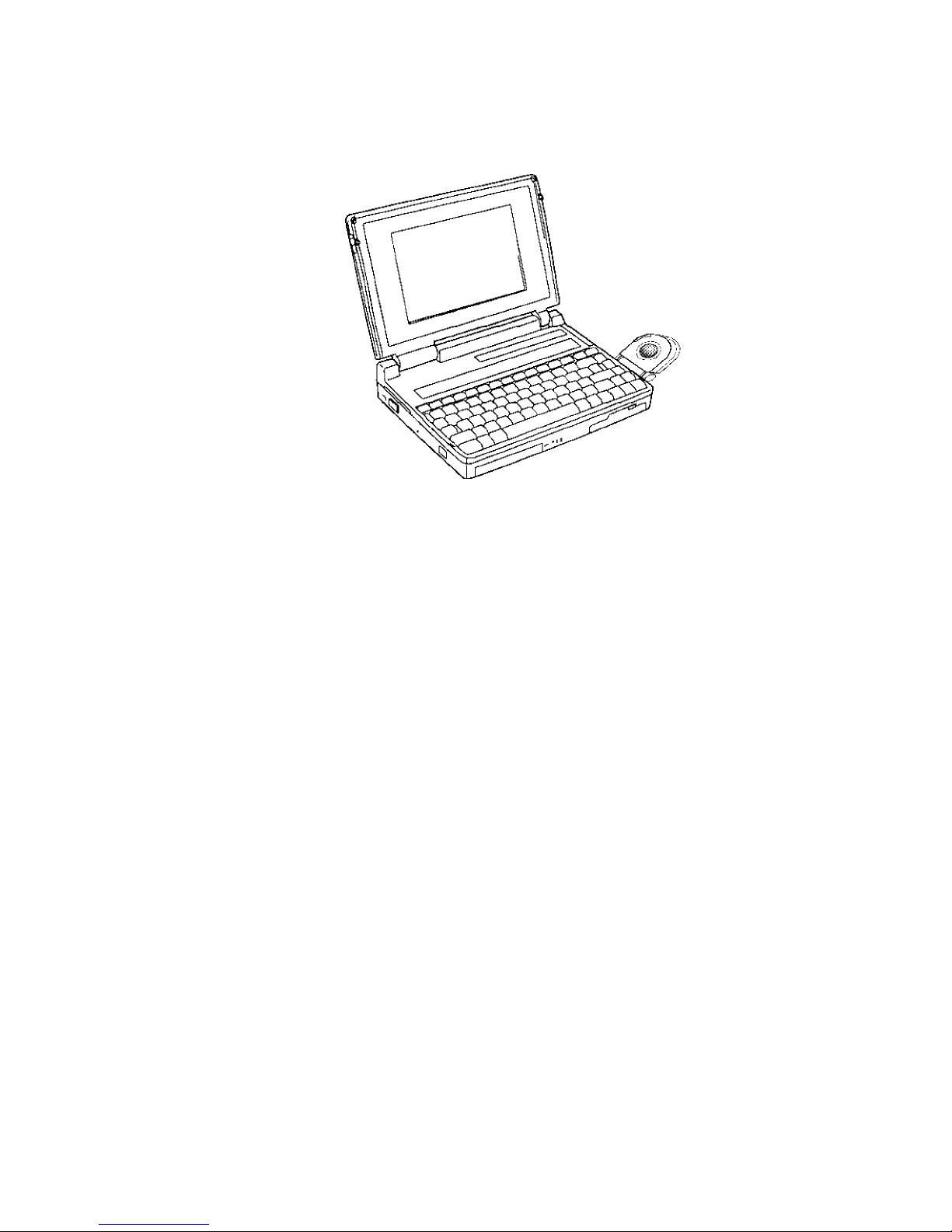
The T4500/T4600 Family Personal Computer is shown in Figure 1-1. The T4500/T4500C system
configuration is shown in Figure 1-2, and the T4600/T4600C system configuration is shown in
Figure 1-3.
Figure 1-1 T4500/T4600 Family Personal Computer
Figure 1-2 T4500/T4500C System Unit Configuration
1-3
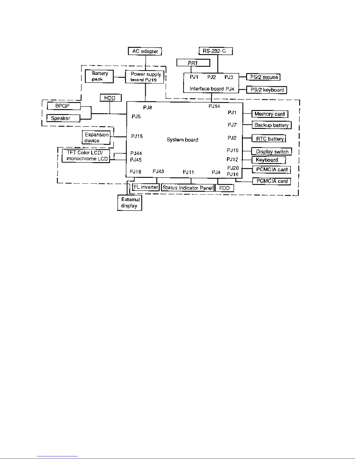
Figure 1-3 T4600/T4600C System Unit Configuration
1-4

1.2 System Unit Block Diagram
Figure 1-4 is a block diagram of the T4500/T4500C system unit.
Figure 1-4 T4500/T4500C System Board Block Diagram
1-5

The T4500 and T4500C system board shown in Figure 1-4 is composed of the following major
components:
❑ An i486SX-20 CPU
❑ Super Integration (SI) T9901, which stores the following components:
●
Two Direct Memory Access Controllers (DMAC): 82C37
●
Two Programmable Interrupt Controllers (PIC): 82C59
●
One Programmable Interval Timer (PIT): 82C54
●
One Floppy Disk Controller (FDC): TC8565
●
One Serial Input/Output Controller (SIO): TC8570
●
One Variable Frequency Oscillator (VFO): TC8568
●
One I/O Controller
●
One Printer Port Controller
●
One Speaker Controller
❑ A Real Time Clock (RTC)
One T9934 chip is used. The T9934 has 128 bytes of memory. Fourteen bytes of memory
are used for the calendar and clock. The remaining 114 bytes are used for the system
configuration data.
❑ A Keyboard Controller (KBC)
One M37452M4 chip is used. This KBC includes the keyboard scan controller and keyboard interface controller. The KBC controls the internal keyboard, external keyboard port,
PS/2 mouse port, and ball point quick port.
❑ Memory configurations
Standard RAM: 4 MB
Cache memory: 8 KB (inside CPU)
BIOS ROM: 128 KB (96 KB are used)
This Read Only Memory (ROM) contains Initial Reliability Test (IRT),
Basic Input/Output System (BIOS), and video BIOS.
Video RAM: 512 KB
Optional memory cards expand memory to a maximum of 20 MB.
❑ VGA display controller: WD90C26A (144-pin) (3.3 volt operation)
This controller controls internal and external VGA compatible display. It can display the
internal and external display at the same time.
1-6

❑ Clock Generator receives 14.31818 MHz (X1) and generates the following frequencies:
●
20 MHz for the CPU
●
14.7456 MHz for the COM
●
24 MHz for the FDC and VFO
●
16 MHz is used for GA
●
14.31818 MHz for WD90C26A (for VGA)
OSC (X3) generates 32.768 KHz for RTC.
❑ Gate Array
System Controller Gate Array
This gate array has the following functions:
●
Memory Controller
- DRAM Controller
- CPU Controller
- Compatible Bus Interface Controller
●
Bus Controller
- Compatible Bus Interface Controller
- Compatible Access Controller
- DMAC Controller
- I/O Controller
●
Address Latch Controller
- 32-Bit → 16-Bit Controller
- Address Latch
- DMA Address Generator
- Refresh Address Generator
●
I/O Register
- Compatible I/O Port
- Saving the data of the Register (in resume) Controller
- Toshiba Special Register
●
20 MHz/10 MHz Controller
- Data Bus Change Controller
- Data Latch
Sub LCD Controller Gate Array
This gate array has the following functions:
●
Status Indicator Panel Controller
- LCD Segment Flashing Controller
●
Internal Communication Controller
- KBC/Power Supply Micro Processor/Main CPU Communication
Controller
- KBC/Power Supply Micro Processor Interrupt Controller
1-7

IC Card Controller Gate Array
This gate array has the following functions:
●
IC Card Controller
- PCMCIA IC Card Controller
- Toshiba Modem Card Controller
●
EEPROM (for security) Controller
- KBC-Security-EEPROM Communication Controller
●
Others
- KBC Communication Controller
- Disable the PRT/FDD Port, HDD Access Controller
- Suspend/Resume Controller
The block diagram of the T4600 and T4600C system board is shown in Figure 1-5.
Figure 1-5 T4600/T4600C System Board Block Diagram
1-8

The T4600 and T4600C system board shown in Figure 1-5 is composed of the following major
components:
❑ An i486SL-33 CPU
❑ One Intel 82360SL
This component is super set with the i486SL microprocessor and stores the following CPU
peripheral components:
●
Two DMACs 8237 equivalent
●
Two PICs 8259 equivalent
●
Two PITs 8254 equivalent (T4600 and T4600C uses one PIT.)
●
Two SIOs 16450 equivalent (T4600 and T4600C uses one SIO.)
●
One RTC MC146818AF equivalent
●
One EPP (Enhanced Parallel Port) controller
❑ One super integration (SI) T9920
The components include the following:
●
One FDC TC8565 equivalent
●
One VFO TC8568 equivalent
●
One speaker controller
❑ A Keyboard Controller (KBC): M37452M4
This KBC includes the keyboard scan controller and keyboard interface controller. The
KBC controls the internal keyboard, external keyboard port, PS/2 mouse port, and ball point
quick port.
❑ The following memories:
Standard RAM: 4 MB
Cache memory: 8 KB (inside CPU)
BIOS ROM: 128 KB (96 KB are used)
This Read Only Memory (ROM) contains Initial Reliability Test (IRT),
Basic Input/Output System (BIOS), and video BIOS.
Video RAM: 512 KB
Optional memory cards expand memory to a maximum of 20 MB.
❑ VGA display controller: WD90C26A (144-pin) (3.3 volt operation)
This controller controls internal and external VGA compatible displays. It can display the
internal and external displays at the same time.
1-9

❑ Clock Generator receives 14.31818 MHz (X1) and generates the following frequencies:
●
66.6 MHz for the CPU
●
14.7456 MHz for the COM
●
24 MHz for the FDC and VFO
●
16 MHz is used for GA
●
14.31818 MHz for WD90C26A (for VGA)
OSC (X3) generates 32.768 KHz for RTC (inside of the 82360SL).
❑ A Power Supply Controller (PSC): TMP90PH48
❑ Gate Array
Sub LCD Controller Gate Array
This gate array has the following functions:
●
Status Indicator Panel Controller
- LCD Segment Flashing Controller
●
Internal Communication Controller
- KBC/Power Supply Micro Processor/Main CPU Communication
Controller
- KBC/Power Supply Micro Processor Interrupt Controller
IC Card Controller Gate Array
This gate array has the following functions:
●
IC Card Controller
- Two cards support PCMCIA Card Controller
- Toshiba Modem Card Controller
●
EEPROM (for security) Controller
- KBC-Security-EEPROM Communication Controller
●
Others
- KBC Communication Controller
- Disable the HDD/FDD/SIO Access Controller
- Suspend/Resume Controller
1-10
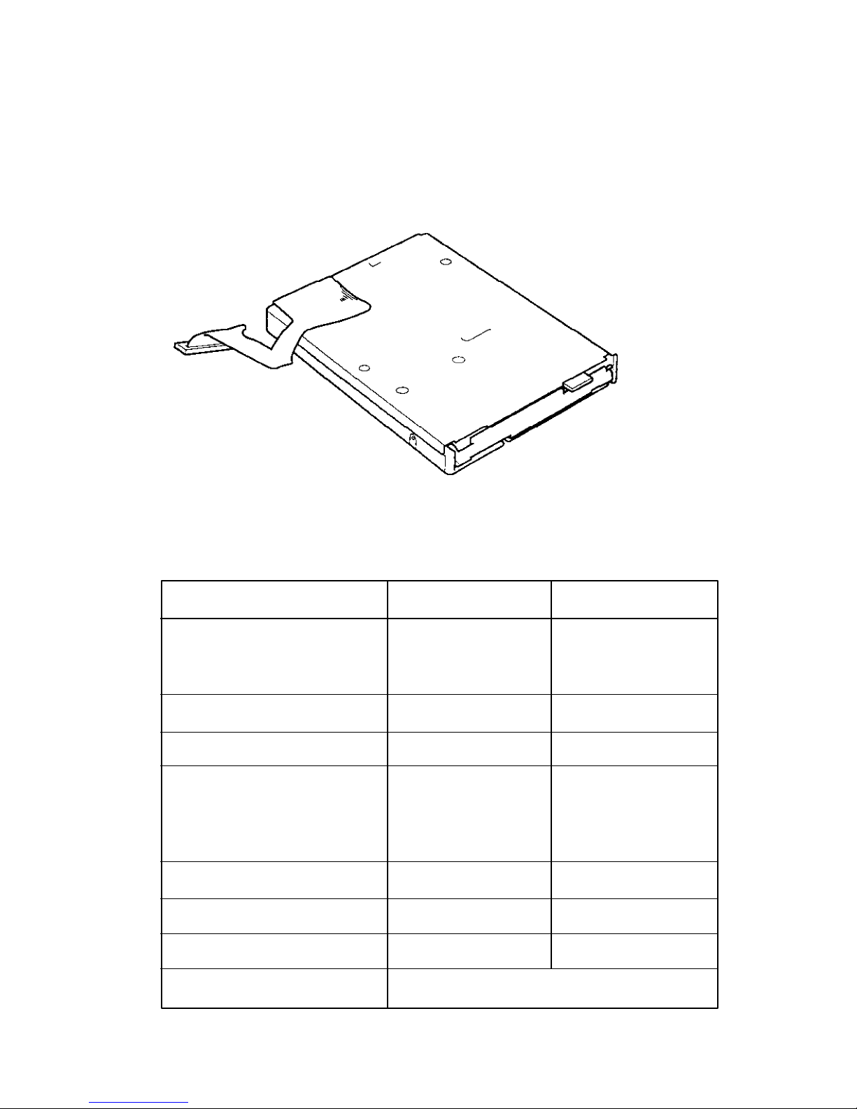
1.3 3.5-inch Floppy Disk Drive
The T4500/T4600 Family 3.5-inch Floppy Disk Drive (FDD) is a thin, high-performance reliable
drive that supports 720-KB (formatted) 2DD and 1.44-MB (formatted) 2HD 3.5-inch floppy disks.
The T4500/T4600 Family FDD is shown in Figure 1-6. The specifications for the FDD are described in Table 1-1.
Figure 1-6 3.5-inch FDD
Table 1-1 3.5-inch FDD Specifications
Item 2-MB mode 1-MB mode
Storage capacity (KB)
Unformatted 2,000 1,000
Formatted 1,311 737
Number of heads 2 2
Number of cylinders 80 80
Access time (ms)
Track to track 3 3
Average 181 181
Head settling time 15 15
Recording track density (tpi) 135 135
Data transfer rate (Kbps) 500 250
Rotation speed (rpm) 300 300
Recording method Modified Frequency Modulation (MFM)
1-11
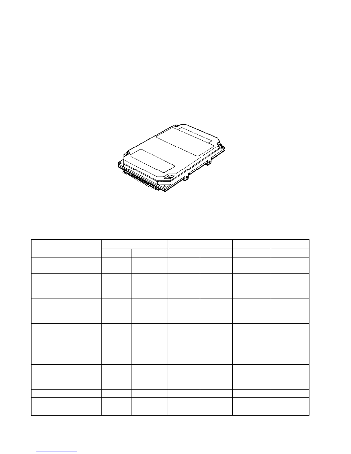
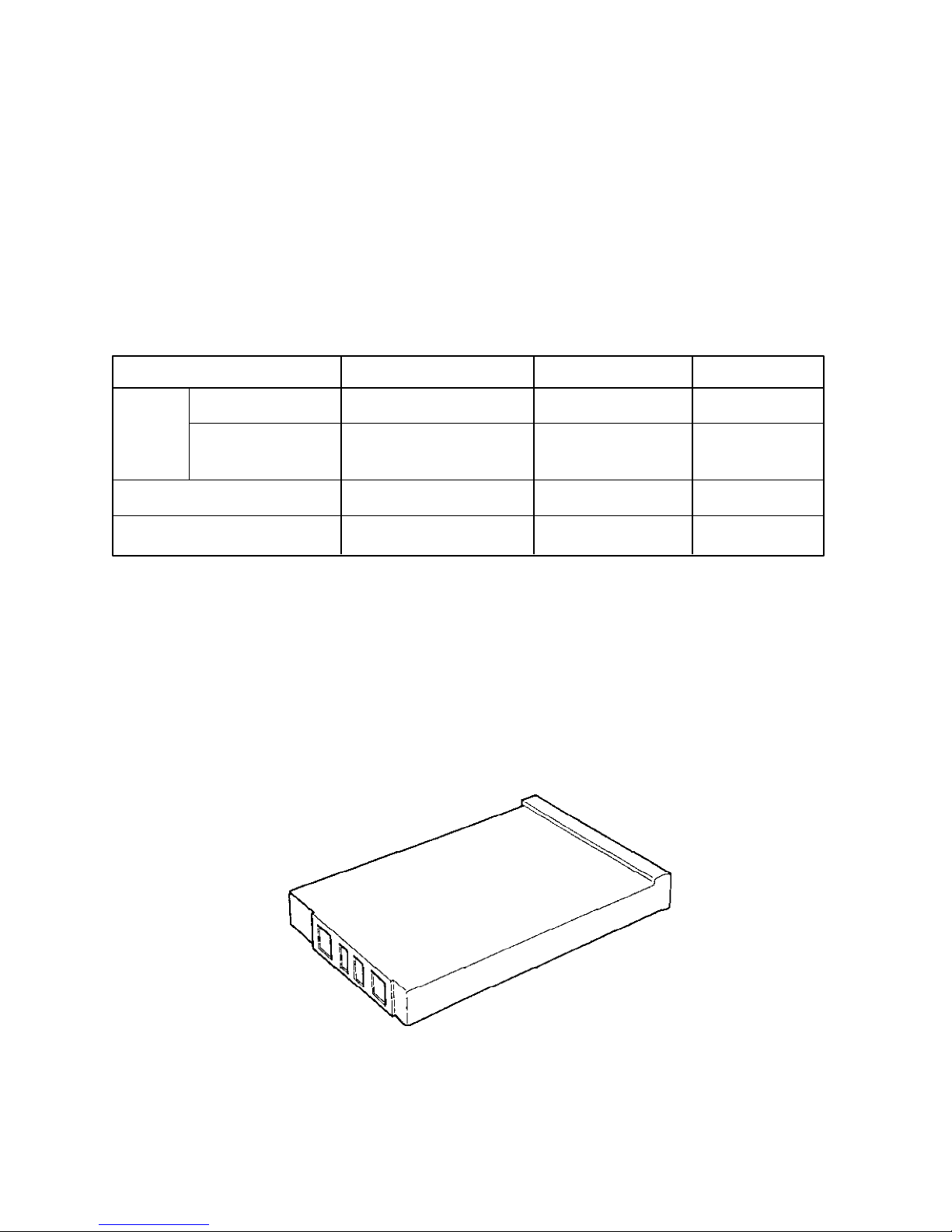
1.4 2.5-inch Hard Disk Drive
The Hard Disk Drive (HDD) is a random access non-volatile storage device. It has a non-removable 2.5-inch magnetic disk and mini-winchester type magnetic heads.
T4500 and T4500C supports the 80 MB, 120 MB, and 200 MB. T4600 and T4600C supports the
120 MB, 200 MB, and 320 MB.
The T4500/T4600 Family HDD is shown in Figure 1-7. Specifications for the HDD are described
in Table 1-2.
Figure 1-7 2.5-inch HDD
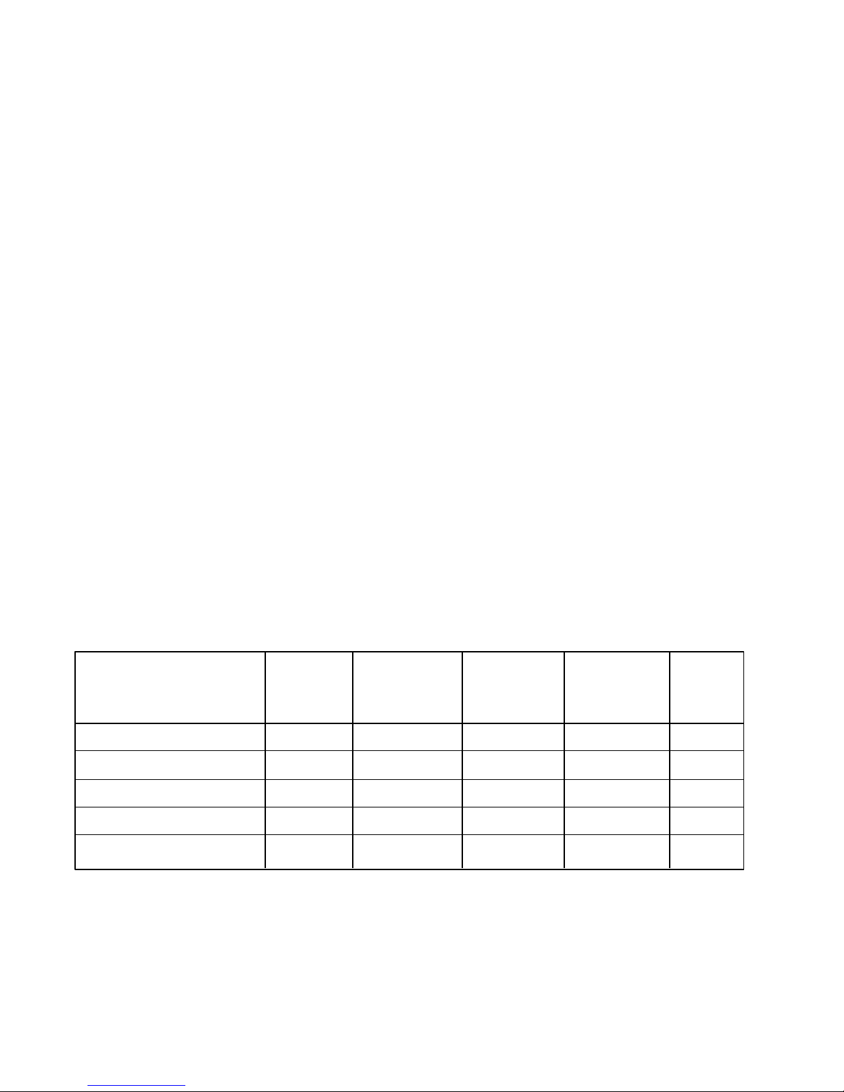
Table 1-2 2.5-inch HDD Specifications
80MB 120 MB 200 MB 320 MB
(CP2084)(MK1422FCV)(CP2124)(MK2124FC)(MK2224FC)(MK2326FC)
Storage capacity (MB)
Formatted 85.4 86.0 121.6 130.1 213.0 340.0
Number of disks 2 1 2 2 2 3
Data heads 4 2 4 4 4 6
Data surfaces 4 2 4 4 4 6
Tracks per surface 1,150 1,501 1,123 1,155 1,560 1,830
Sectors per track 38 (+1) 56 (+1) 53 (+1) 55 (+1) – –
Bytes per sector 512 512 512 512 512 512
Access time (ms)
Track to track 5 3 3 5 3 3
Average 19 15 16 17 12 12
Maximum 40 25 30 36 25 25
Rotation speed (rpm) 3,486 3,600 3,743 3,200 4,000 4,200
Data transfer rate (bps)
To/from media 12 M 17.6 M 18 M 15.3 M 18.9 to 18.7 to
31.6 M 29.6 M
Interleave 1:1 1:1 1:1 1:1 1:1 1:1
Recording method 2-7RLL/ 1-7 RLL 2-7 RLL/ 1-7 RLL 1-7 RLL 1-7 RLL
1-7 RLL 1-7 RLL
1-12
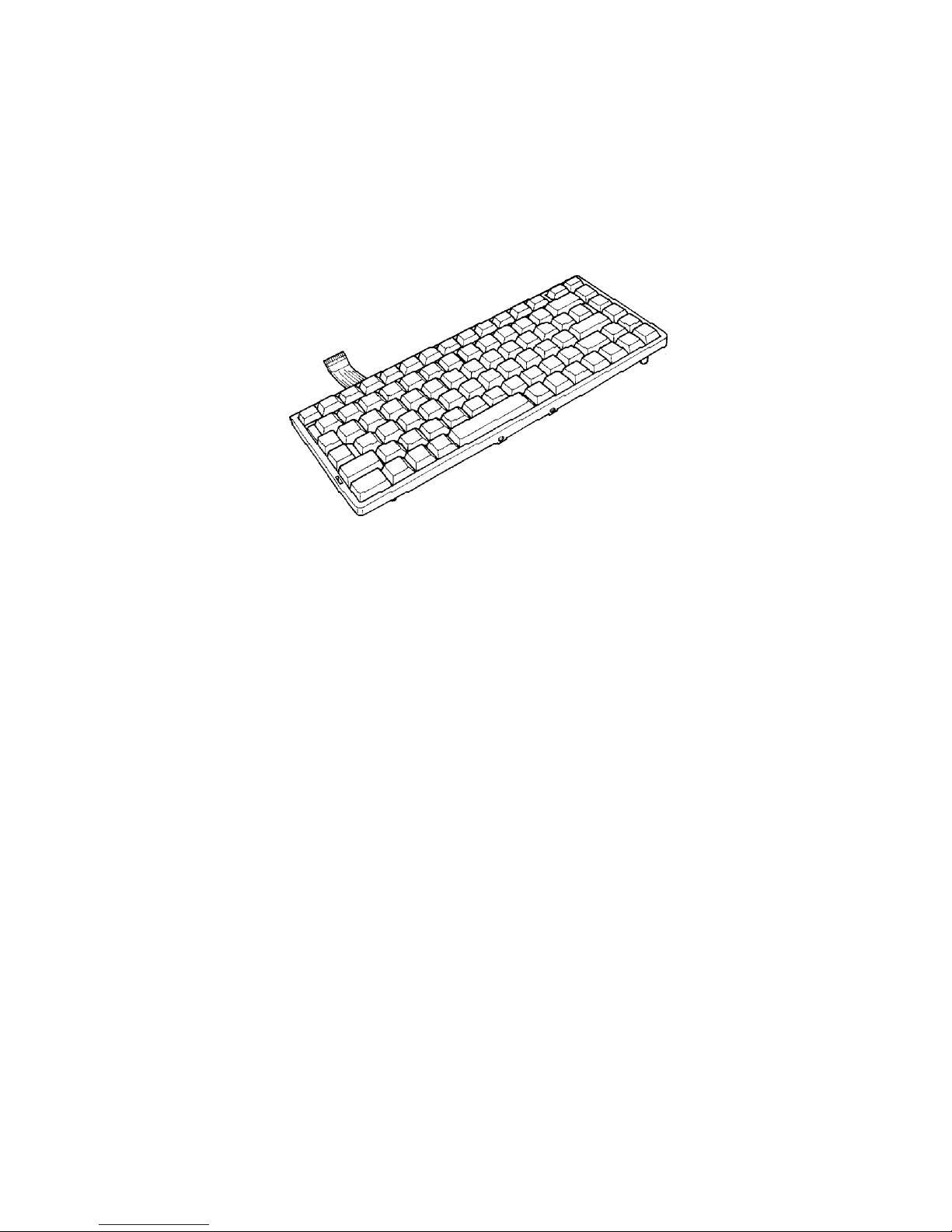
1.5 Keyboard
The 82-(USA) or 84-(European) keyboard is mounted on the T4500/T4600 Family system unit.
The keyboard is connected to the keyboard controller on the system board through a 19-pin flat
cable. The keyboard is shown in Figure 1-8.
See Appendix F for optional keyboard configurations.
Figure 1-8 Keyboard
1-13

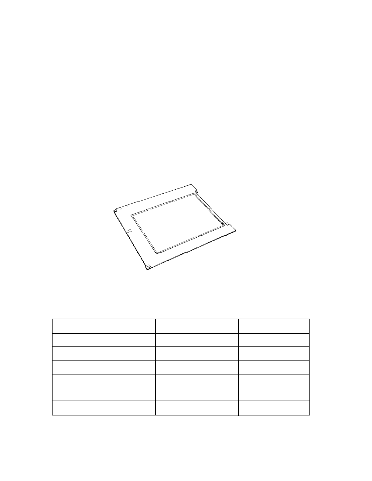
1.6 Sidelit Liquid Crystal Display (T4500 & T4600)
The sidelit Liquid Crystal Display (LCD) is composed of an LCD module, a Fluorescent Lamp
(FL), and an FL inverter board.
1.6.1 LCD Module (T4500 & T4600)
The T4500/T4600 sidelit LCD supports 640 x 480 pixels with a High Resolution Graphics Subsystem (HRGS) and 64 levels of gray. The HRGS includes the functions of the Video Graphics
Array (VGA).
The LCD receives vertical and horizontal synchronizing signals, 8-bit data signals (4-bit upper data
signal and 4-bit lower data signal), and shift clock for data transmission. All signals are CMOSlevel compatible.
The sidelit LCD is shown in Figure 1-9 and its specifications are described in Table 1-3.
Table 1-3 Sidelit LCD Specifications
Item Specifications
Number of Dots (dots) 640 x 480
Dot pitch (mm) 0.30 (W) x 0.30 (H)
Display area (mm) 192 (W) x 144 (H)
Contrast 17:1 (typically)
FL current (mA) 5.0
FL frequency (KHz) 42
1-14
Figure 1-9 Sidelit LCD
1.6.2 Fluorescent Lamp (FL) Inverter Board (T4500 & T4600)
The FL inverter board supplies the high frequency current needed to illuminate the FL.
The specifications for the FL inverter board are described in Table 1-4.
Table 1-4 FL Inverter Board Specifications
Item Specifications
Input Voltage (VDC) 10
Power (W) 2.6
Output Voltage (VAC) 1,100
Current (mA) 5.0
Frequency (KHz) 42
Current limits (mA) 2.5 ~ 5.0
1-15
1.7 TFT Color LCD Display (T4500C & T4600C)
The TFT Color Liquid Crystal Display (LCD) contains an LCD module, a Fluorescent Lamp (FL),
and an FL inverter board.
1.7.1 TFT Color LCD Module (T4500C & T4600C)
The T4500C and T4600C TFT color LCD is backlit and supports 640 x 480 pixels with a High
Resolution Graphics Subsystem (HRGS) and 512 colors for graphics and characters. This HRGS
includes the functions of Video Graphics Array (VGA).
The T4500C’s LCD receives vertical and horizontal synchronizing signals, 9-bit data signals, data
enable signals, and shift clock for data transmission. The T4600C’s LCD receives 9-bit data
signals, data enable signals, and shift clock for data transmission. All signals are CMOS-level
compatible.
The TFT LCD is shown in Figure 1-10. The specifications for the LCD are described in Table 1-5.
1-16
Figure 1-10 TFT Color LCD
Table 1-5 TFT Color LCD Specifications
Item T4500C T4600C
Number of Dots (dots) 640 x 480 640 x 480
Dot pitch (mm) 0.267 (W) x 0.27 (H) 0.3 (W) x 0.3 (H)
Display area (mm) 171 (W) x 130 (H) 192 (W) x 144 (H)
Contrast 60:1 (minimum) 60:1 (minimum)
FL current (mA) 5.0 5.0
FL frequency (KHz) 47 47
1.7.2 Fluorescent Lamp (FL) Inverter Board (T4500C & T4600C)
The FL inverter board supplies high frequency current to light the LCD’s Fluorescent Lamp.
The specifications for the FL inverter are described in Table 1-6.
Table 1-6 FL Inverter Board Specifications
Item T4500C T4600C
Input Voltage (VDC) 10 18
Power (W) 6 6
Output Voltage (VAC) 1,100 1,100
Current (mA) 5.0 5.0
Frequency (KHz) 47 47
Current limits (mA) 3.0 to 5.0 3.0 to 5.0
1-17
1.8 Power Supply Board
The power supply board supplies five kinds of voltages to the T4500/T4600 Family system board.
The T4500/T4600 Family power supply board has one microprocessor and it operates at 500 KHz
(power off) or 20 MHz (power on).
The power supply board performs the following functions:
1. Determines if the AC adapter or battery is connected to the computer.
2. Detects DC output and circuit malfunctions.
3. Controls the LED indicator and speaker.
4. Controls the Battery capacity icon, Power on icon and AC adapter icon on the status indicator panel.
5. Turns the battery charging system on and off and detects a fully charged battery.
6. Determines if the power can be turned on and off.
7. Provides more accurate detection of a low battery.
8. Calculates the remaining battery capacity.
The power supply board output rating is specified in Table 1-7.
Table 1-7 Power Supply Board Output Rating
DC Regulation Maximum
Use for Name voltage tolerance current Ripple
(V) (%) (mA) (mV)
System logic, FDD, HDD VCC +5 ±5 2,600 100
RS-232-C, Flash ROM 12V +12 ±5 120 240
Display DSPV +7.5 to +23 – 7W –
RAM, CPU B3V +3.3 ±5 755 66
RS-232-C M12V –7 to –12.6 – 10 –
1-18
1.9 Batteries
The T4500/T4600 Family has three types of batteries:
❑ Main battery pack
❑ Backup battery
❑ Real Time Clock (RTC) battery
Specifications for these batteries are listed in Table 1-8.
Table 1-8 Battery Specifications
Main
Battery
Backup battery Nickel Metal Hydride 1.2 V 1,100 mAH
RTC battery Lithium-Vanadium 3.0 V 50 mAH
Battery name Material Output voltage Capacity
T4500 Nickel Cadmium 9.6 V 2,400 mAH
T4500C, Nickel Metal Hydride 9.6 V 3,000mAH
T4600, T4600C
1.9.1 Main Battery
The removable main battery pack is the computer’s main power source when the AC adapter is not
attached. The main battery recharges the backup battery when the system’s power is on. The
backup and main battery maintain the state of the computer when you enable AutoResume, and
they maintain the information in Hard RAM.
The main battery is shown in Figure 1-11.
Figure 1-11 Main Battery
1-19

Battery Indicator LED
The Battery Indicator LED is located next to the battery pack slot on the front of the T4500/T4600
Family computer and is identified by a battery icon. The indicator shows the status of the removable battery pack, power supply, and AC adapter.
The status of each can be determined by color:
Orange The battery is being charged. (AC adapter is attached.)
Green The battery is fully charged. (AC adapter is attached.)
No light The AC adapter is disconnected from the computer or the AC adapter is attached,
but it cannot charge the battery for one of the following reasons:
❑ The battery is extremely hot. Allow the computer and the battery to reach room
temperature before attempting to charge the battery.
❑ The battery is almost fully discharged. The battery will not begin charging
immediately in this state, it will begin charging a few minutes after the AC
adapter is connected.
Main Battery’s Overload Protective Circuit
The main battery circuit is shown below:
Figure 1-12 Main Battery Circuit (Nickel Cadmium)
1-20
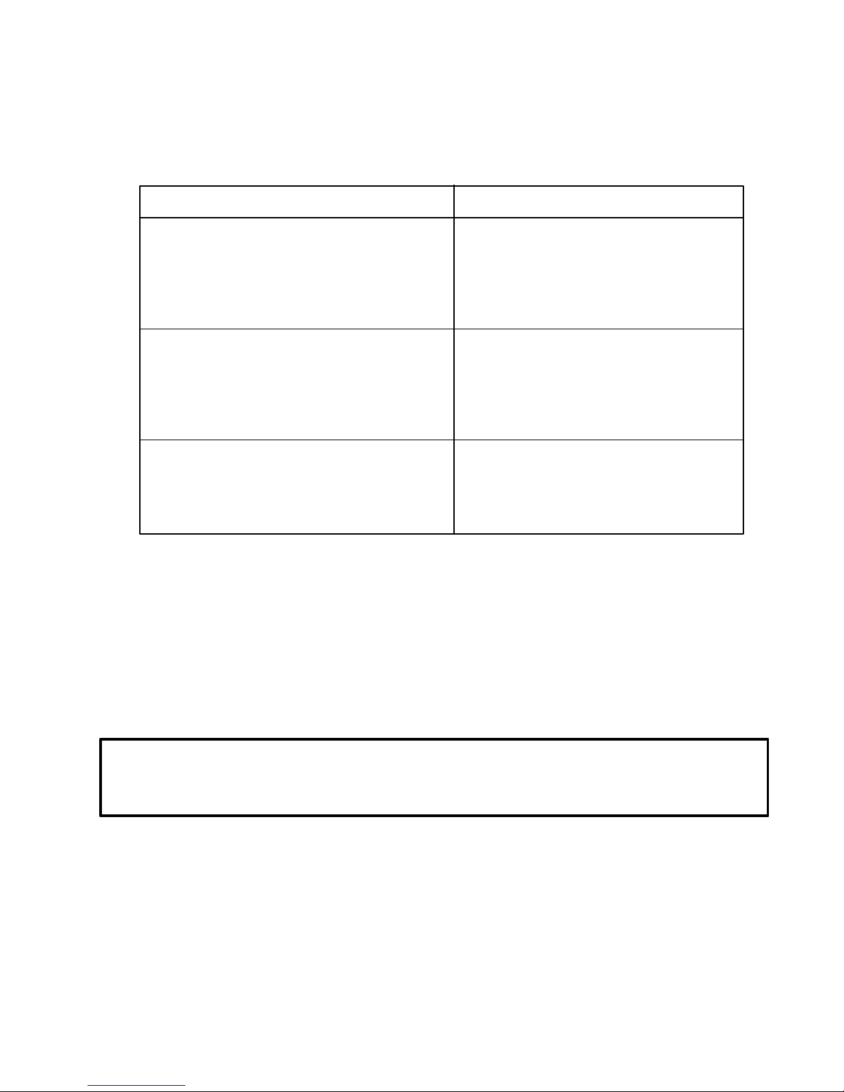
Figure 1-13 Main Battery Circuit (Nickel Metal Hydride)
The T4500/T4600 Family’s main battery has three devices to prevent circuit overload. Table 1-9
shows the overload specifications.
Table 1-9 Circuit Overload Protection Devices for Main Battery
(Nickel Cadmium/Nickel Metal Hydride)
Protection Method Rating/Function
➊ Thermal protector
Electrical rating 12 VDC, 3 A
Maximum circuit breaker current 12 VDC/120 A
Allowable operating temperature 60° ~ 75°
➋ Thermal fuse
Current rating 10 A
Voltage rating 250 V
Temperature rating 91° C
➌ Thermal sensor (Monitors the battery’s temperature)
Load resistance 10 kΩ ±1% (at 25° C)
Operating temperature limits -50° ~ 100° C
➊ Thermal protector
When the temperature falls outside the operating range of 60° to 75° C, the thermal protector reduces the current by increasing the internal resistance.
➋ Thermal Fuses
If the temperature exceeds 91° C, the thermal fuses may blow to protect the battery and the
system.
WARNING: Never try to use a battery unless its fuses are intact. Do not try to replace a
battery fuse or try to bypass a fuse. Using a defective battery can permanently damage the
system and can cause injury.
➌ Thermal sensor
The thermal sensor monitors the temperature of the battery.
➍ T line
The thermal sensor monitors the temperature of the battery and changes the voltage in the T
line accordingly. The power supply microprocessor monitors the voltage changes in the T
1-21
line.
➎ S line
The power supply microprocessor determines the type of battery by whether the S line is
connected to the battery circuit. If the S line is connected to the negative line, the power
supply microprocessor determines that a Nickel Metal Hydride Battery is installed in the
computer. If the S line is not connected, the power supply microprocessor determines that a
Nickel Cadmium Battery is installed in the computer.
1.9.2 Battery Charging Control
Battery charging is controlled by a power supply microprocessor that is mounted on the power
supply. The microprocessor controls whether the charge is on or off and detects a full charge when
the AC adapter and battery are attached to the computer. The system charges the battery using
quick charge or trickle charge.
Quick Battery Charge
When the AC adapter is attached, there are two types of quick charge: quick charge 1 when the
system is powered off, and quick charge 2 when the system is powered on.
Table 1-10 Quick Charge Times
Kind of battery Charging time
Quick charge 1 Nickel Cadmium About 1 hour, 10 minutes
(power off) Nickel Metal Hydride About 1 hour, 30 minutes
Quick charge 2 Nickel Cadmium 1.5 to 4 hours (typical: 2 hours)
(power on) Nickel Metal Hydride 1.5 to 5 hours (typical: 3 hours)
NOTES 1: The time required for quick charge 2 is affected by the amount of power the
system is consuming. Use of the fluorescent lamp and frequent disk access
diverts power and lengthens the charge time.
2: Using quick charge 1, the system CPU automatically stops the charge after
two hours regardless of the condition of the battery.
If one of the following occurs, the battery quick-charge process stops.
1. The battery becomes fully charged
2. The AC adapter or battery is removed.
1-22
3. The battery or output voltage is abnormal.
Data preservation period (full charge) 1 month
Trickle Battery Charge
When the main battery is fully charged and the AC adapter is attached, the microprocessor automatically changes quick charge 1 or 2 to trickle charge.
Detection of full charge
A full charge is detected only when the battery is charging at quick charge. A full charge is detected under any of the following conditions:
1. A battery voltage fall is detected.
2. The charging time exceeds the fixed limit.
3. The thermal rise (+DT) exceeds the fixed limit.
4. The battery’s temperature is over 60°C.
1.9.3 Backup Battery
The backup battery maintains data for AutoResume and Hard RAM. The power source used to
back up the AutoResume or Hard-RAM data is determined according to the following priority:
AC adapter > Main battery > Backup battery
The backup battery is charged by the main battery or AC adapter when the system is powered on.
Table 1-11 shows the charging time and data preservation period of the backup battery.
Table 1-11 Backup Battery Charging/Data Preservation Time
Time
Charging Time Power On 20 H
Power Off Doesn’t charge
Data preservation period (full charge) 8.0 H
1.9.4 RTC battery
The RTC battery provides power to keep the current date, time and other setup information in
memory while the computer is turned off. Table 1-12 shows the charging time and data preservation period of the RTC battery.
Table 1-12 RTC Battery Charging/Data Preservation Time
Charging Time Power On 24 H
Time
Power Off 24 H
1-23

1-24

2.1 T4500/T4600 Family Troubleshooting
Chapter 2 describes how to determine if a Field Replaceable Unit (FRU) in the T4500/T4600
Family is causing the computer to malfunction. The FRUs covered are:
❑ System PCB
❑ Floppy Disk Drive
❑ Hard Disk Drive
❑ Keyboard
❑ Display
❑ Status Indicator Panel
The Diagnostics Disk operations are described in Chapter 3, Tests and Diagnostics and detailed
disassembly and reassembly procedures are given in Chapter 4, Replacement Procedures.
The following tools are necessary for implementing the troubleshooting procedures:
1. A T4500/T4500C Diagnostics Disk or T4600/T4600C Diagnostics Disk
2. A Phillips head screwdriver (2 mm)
3. A Toshiba MS-DOS system disk
4. A 2DD or 2HD formatted work disk for floppy disk drive testing
5. A cleaning kit for floppy disk drive troubleshooting
6. A printer port LED
7. An RS-232-C wraparound connector
8. A printer wraparound connector
9. A multimeter
10. An external 5.25-inch floppy disk drive (only T4500 and T4500C)
11. An external CRT
2-1

2.2 Troubleshooting Flowchart
Use the flowchart in Figure 2-1 as a guide for determining which troubleshooting procedures to
execute. Before going through the flowchart steps, verify the following:
❑ Ask the user if a password is registered, and if it is, ask him or her to enter it. If the user
has forgotten the password, refer to Appendix H for information on password deletion.
❑ Verify with the customer that Toshiba MS-DOS is installed on the hard disk. Non-Toshiba
operating systems can cause the computer to malfunction.
❑ Make sure all optional equipment is disconnected from the computer.
❑ Make sure the floppy disk drive is empty.
2-2
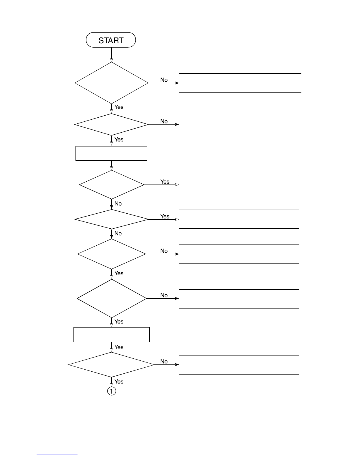
Is the
AC adapter
icon displayed on the Status
Indicator Panel when the AC
adapter is con-
nected?
Perform the Power Supply Troubleshooting
procedures in Section 2.3.
Does
the Battery LED
glow?
Turn the power switch on while
pressing the spacebar.
Is
the P** mes-
sage displayed on the SUB
error message displayed?
LCD?
Is an
Is
the
"MEMORY TEST
XXXKB" message
displayed?
Perform the Power Supply Troubleshooting
procedures in Section 2.3.
Perform the Power Supply Troubleshooting
procedures in Section 2.3.
Perform the System PCB Troubleshooting
procedures in Section 2.4.
Perform the Display Troubleshooting procedures in Section 2.8.
Does
the "MEMORY
TEST XXXKB" message pro-
ceed from 0KB and
640KB?
If the "Password=" message displays,
type the password, then press
Is
Toshiba MS-DOS
being loaded?
Figure 2-1 Troubleshooting Flowchart (1 of 2)
Enter
Perform the System PCB Troubleshooting
procedures in Section 2.4.
.
Perform the Hard Disk Drive Trouble-
shooting procedures in Section 2.6.
2-3
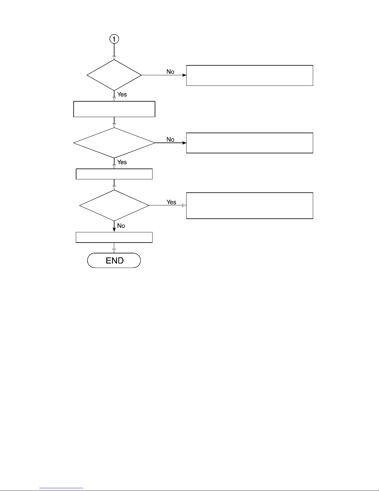
Do typed
characters appear
correctly?
Insert the diagnostics disk into the FDD,
then run the diagnostics test program.
Perform the Keyboard Troubleshooting
procedures in Section 2.7.
Did
the diagnostics
test program load
properly?
Perform each test.
Is
an error
detected by any of the
diagnostic tests?
The system is normal.
Figure 2-1 Troubleshooting Flowchart (2 of 2)
Perform the Floppy Disk Drive Troubleshooting procedures in Section 2.5.
After confirming which diagnostic test has
detected an error, perform the appropriate
procedures as outlined below.
If the diagnostics program cannot detect an error, the problem may be intermittent. The Running
Test program should be executed several times to isolate the problem.
Check the Log Utilities function to confirm which diagnostic test detected an error(s), then perform the appropriate troubleshooting procedures as follows:
1. If an error is detected on the system test, memory test, display test, ASYNC test, printer
test, or real timer test, perform the System PCB Troubleshooting procedures in Section 2.4.
2. If an error is detected on the keyboard test, perform the Keyboard Troubleshooting procedures in Section 2.7.
3. If an error is detected on the floppy disk test, perform the Floppy Disk Drive Troubleshoot-
ing procedures in Section 2.5.
4. If an error is detected on the hard disk test, perform the Hard Disk Drive Troubleshooting
procedures in Section 2.6.
2-4
2.3 Power Supply Troubleshooting
The T4500/T4600 Family’s power supply controls many functions and components. To determine
if the power supply is functioning properly, start with Procedure 1 and continue with the other
procedures as instructed. The procedures described in this section are:
Procedure 1: Power Status Check on the Status Indicator Panel
Procedure 2: Battery LED Indicator Check
Procedure 3: Battery Power Check
Procedure 4: System PCB Replacement Check
Procedure 1 Power Status Check on the Status Indicator Panel
The Status Indicator Panel displays the status of the following power-related items:
❑ AC adapter or Desk Station IV connection status
❑ System power-on status
❑ Remaining battery power
If an error status is displayed on the Status Indicator Panel, perform Check 1. If the Battery LED
Indicator is flashing red or not glowing, go to Procedure 2. If the three icons listed above are not
displayed, go to Procedure 3.
NOTE: The power supply microprocessor monitors the status of the power supply. When it
detects an error, the error is displayed on the Status Indicator Panel.
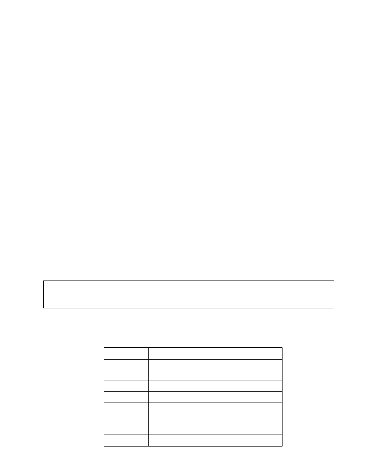
Check 1: Read the error status in the battery power indicator area on the Status Indicator Panel.
Table 2-1 Outline of Power Supply Error Status
Status Source of Error
P0* AC Adapter or Desk Station IV error
P1* Battery error
P2* VCC Output error
P3* B3V Output error
P4* 12V Output or M12V Output error
P5* Power Supply Microcomputer error
P6* Power On error
P8* Environment
2-5
❑ Adapter (AC Adapter or Desk Station)
Status Meaning
P01 AC Adapter Voltage is over the maximum allowable limit.
P02 Desk Station Voltage is over the maximum allowable limit.
❑ Battery
Status Meaning
P10 Charge current is over the maximum allowable limit.
❑ VCC Output
Status Meaning
P20 VCC Voltage is over the maximum allowable limit.
P21 VCC Voltage is below the minimum allowable limit.
P22 VCC Voltage is output at a low level (does not fall to zero) while the
power is off.
❑ B3V Output
Status Meaning
P30 B3V Voltage is over the maximum allowable limit.
P31 B3V Voltage is below the minimum allowable limit.
P32 B3V Voltage is not within the normal range while the system is on.
P33 B3V Voltage is not within the normal range while the system is in
the resume mode or Hard-RAM is enabled.
❑ Output Voltage (12V or M12V)
Status Meaning
P40 12V Voltage is over the maximum allowable limit.
P41 12V Voltage is below the minimum allowable limit.
P42 M12V Voltage is not within the normal range
2-6

❑ Power Supply Microprocessor
Status Meaning
P50 Firmware error.
P52 Program error.
❑ Power Supply On/Off Sequence
Status Meaning
P60 VCC and B3V error.
❑ Environment
Status Meaning
P80 Temperature is over 70°C or under –20°C
Check 2: When P02 is displayed, perform the following steps:
1. Make sure the Desk Station IV is firmly connected to the computer’s expansion bus
port. If this port is connected correctly, proceed to step 2:
2. Replace the Desk Station IV with a new one. If the status still exists, go to Check 4.
Check 3: When P01 is displayed, perform the following steps:
1. Make sure the AC adapter’s cable and AC cord are firmly plugged into the DC IN 15 V
socket and wall outlet. If these cables are connected correctly, proceed to step 2:
2. Connect a new AC adapter. If the status still exists, go to Check 4.
Check 4: When P10 is displayed, perform the following steps:
1. Make sure the battery pack is correctly installed in the computer. If the battery pack is
correctly installed, proceed to step 2:
2. Replace the battery pack with a new one. If the status still exists, go to Procedure 4.
2-7

Check 5: When P80 is displayed, perform the following steps:
1. Move the computer to an area where the temperature is between 20°C and 70°C. If the
status still exists, go to Procedure 4.
Check 6: When P20, P21, P22, P30, P31, P32, P33, P40, P41, P42, P50 or P60 is displayed, go
to Procedure 4.
Procedure 2 Battery LED Check
The Battery LED, identified by a battery icon on the front of the T4500/T4600 Family computer,
indicates the battery charging status.
❑ If the Battery LED indicator glows green, the AC adapter is connected and the battery is
fully charged.
❑ If the Battery LED indicator glows amber, the AC adapter is connected and the battery
is being charged.
❑ If the Battery LED indicator flashes red only 10 times, the sub LCD (Status Indicator
Panel) controller gate array on the System PCB or Power supply microprocessor may be
malfunctioning. Go to Procedure 4.
❑ If the Battery LED indicator does not glow, go to Check 1.
Check 1: Make sure the AC adapter’s cable and AC cord are firmly plugged into the DC IN 15V
socket and wall outlet. If these cables are connected correctly, go to Check 2.
Check 2: Connect a new AC adapter. If the Battery LED indicator still does not glow, go to
Check 3.
Check 3: Make sure the battery pack is installed in the computer correctly. If the battery
pack is installed correctly, go to Check 4.
Check 4: Install a new battery pack. If the Battery LED indicator still does not glow, go to
Procedure 4.
2-8

Procedure 3 Battery Power Check
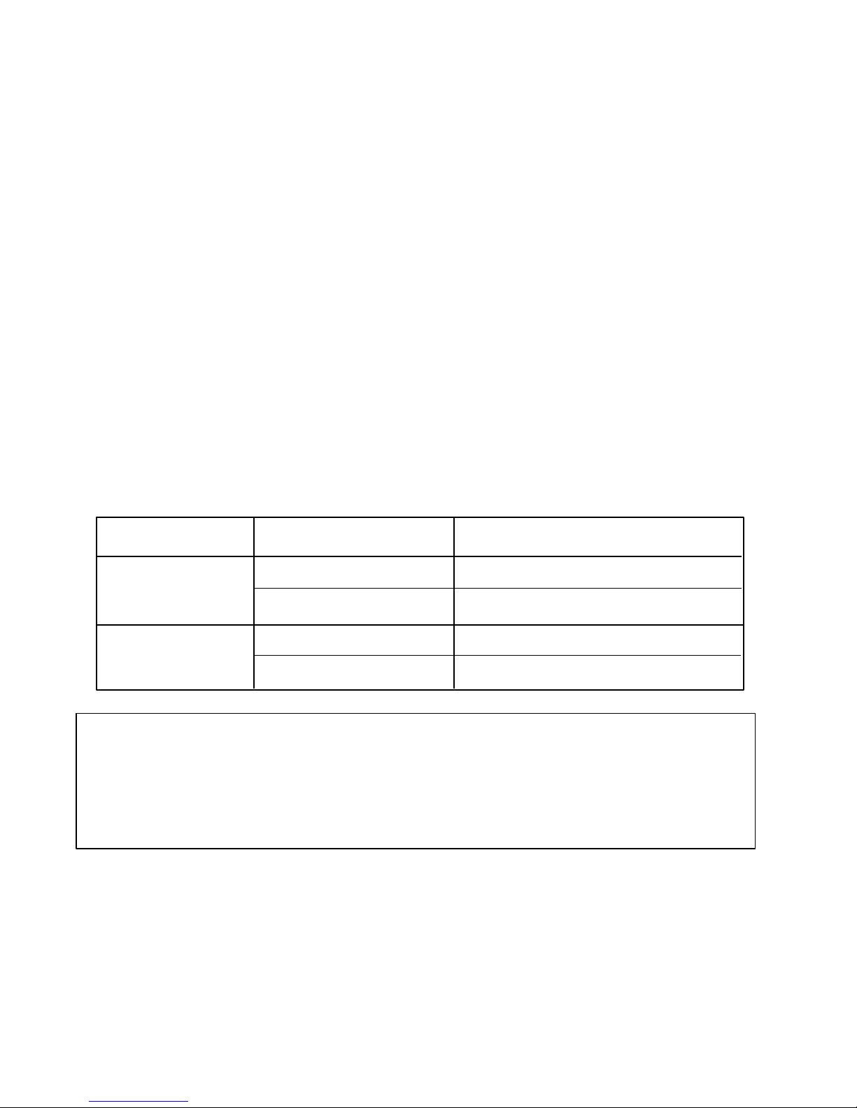
The Status Indicator Panel displays the remaining battery power as shown in Table 2-2.
Table 2-2 Battery Power Status
Battery AC adapter Battery Power (Status Indicator Panel)
Not installed – Does not display
Installed Not connected Time or percent (selected in Setup program)
Connected Only percent
If the battery power is not displayed as indicated in Table 2-2, go to Check 1.
Check 1: Make sure the AC adapter’s cable and AC cord are firmly plugged into the DC IN 15V
socket and wall outlet. If these cables are connected correctly, go to Check 2.
Check 2: Connect a new AC adapter. If the Status Indicator Panel does not change, go to Check 3.
Check 3: Make sure the battery pack is installed in the computer correctly. If the battery pack
is installed correctly, go to Check 4.
Check 4: Install a new battery pack. If the Battery Charging Status indicator still does not
change, go to Section 2.9, Status Indicator Panel Troubleshooting.
Procedure 4 System PCB Replacement Check
The System PCB incorporates both the system board and the power supply board into one unit.
Power is transferred to the power supply board through the DC IN 15 V plug located on the power
supply board. If either the power supply board or the system board is damaged, replace the System
PCB.
Refer to Chapter 4, Replacement Procedures, for instructions on how to disassemble the T4500/
T4600 Family computer, and then perform the following check:
Check 1: Replace the System PCB with a new one and restart the system. If the problem still
exists, other FRUs may be damaged.
2-9

2.4 System PCB Troubleshooting
This section describes how to determine if the system board is defective or not functioning properly. Start with Procedure 1 and continue with the other procedures as instructed. The procedures
described in this section are:
Procedure 1: Message Check
Procedure 2: Printer Port LED Check
Procedure 3: Diagnostic Test Program Execution Check
Procedure 4: System PCB Replacement Check
Procedure 1 Message Check
When the power is turned on, the system performs the Initial Reliability Test (IRT) installed in the
BIOS ROM. The IRT tests each IC on the system board and initializes it.
❑ If an error message is shown on the display, perform Check 1.
❑ If there is no error message, go to Procedure 2.
❑ If the Toshiba MS-DOS is properly loaded, go to Procedure 3.
Check 1: If one of the following error messages is displayed on the screen, press the F1 key as
the message instructs. These errors occur when the system configuration preserved in
the RTC memory (CMOS type memory) is not the same as the actual configuration or
when the data is lost.
If you press the F1 key as the message instructs, the system configuration in the RTC
memory configuration is set to the default setting. If error message (b) appears often
when the power is turned on, replace the RTC battery. If any other error message is
displayed, perform Check 2.
(a) *** Error in CMOS. Bad HDD type ***
Check system. Then press [F1] key ......
(b) *** Error in CMOS. Bad battery ***
Check system. Then press [F1] key ......
(c) *** Error in CMOS. Bad check sum ***
Check system. Then press [F1] key ......
(d) *** Error in CMOS. Bad memory configuration ***
Check system. Then press [F1] key ......
(e) *** Error in CMOS. Bad time function ***
Check system. Then press [F1] key ......
2-10

Check 2: If the following (a) or (b) error message is displayed on the screen, press any key as
the message instructs.
Error message (a) appears when data stored in RAM under the resume function is lost
because the battery has become discharged.
Error message (b) appears when the error is detected during a read test of the Hard
RAM or the data in the Hard RAM is lost because the battery has become discharged.
If any other message appears, perform Check 3.
(a) WARNING: RESUME FAILURE.
PRESS ANY KEY TO CONTINUE.
(b) WARNING: DATA IN HARD-RAM WAS LOST.
YOU MUST FORMAT HARD-RAM BEFORE USE.
PRESS ANY KEY TO CONTINUE.
Check 3: The IRT checks the system board. When the IRT detects an error, the system stops or
an error message appears.
If one of the following error messages (1) through (17), (19), (20), (25) or (26) is
displayed, replace the System PCB.
If error message (18) is displayed, go to the Keyboard Troubleshooting procedures in
section 2.7.
If error message (21) or (22) is displayed, go to the Hard Disk Drive Troubleshooting
procedures in section 2.6.
If error message (23) or (24) is displayed, go to the Floppy Disk Drive Troubleshooting procedures in section 2.5.
(1) TIMER CH.2 OUT ERROR
(2) PIT ERROR
(3) MEMORY REFRESH ERROR
(4) FIRST 64KB MEMORY ERROR
(5) RTC ERROR
(6) CRTC ERROR
(7) VRAM ERROR
(8) KBC ERROR
(9) SYSTEM MEMORY ERROR
2-11

(10) SYSTEM MEMORY PARITY ERROR
(11) EXTENDED MEMORY ERROR
(12) EXTENDED MEMORY PARITY ERROR
(13) DMA PAGE REGISTER ERROR
(14) DMAC #1 ERROR
(15) DMAC #2 ERROR
(16) PIC #1 ERROR
(17) PIC #2 ERROR
(18) KEYBOARD ERROR
(19) KBC ERROR
(20) HDC ERROR
(21) HDD #0 ERROR
(22) HDD #1 ERROR
(23) NO FDD ERROR
(24) FDD ERROR
(25) TIMER INTERRUPT ERROR
(26) RTC UPDATE ERROR
Procedure 2 Printer Port LED Check
The printer port LED displays the IRT status and test status by turning lights on and off as an eightdigit binary value. Figure 2-2 shows the printer port LED.
NOTE: When you perform this check, the external FDD/PRT (T4500 and T4500C) or
parallel port (T4600 and T4600C) option in the SETUP program must be set to PRT (T4500
and T4500C) or LPT1 (T4600 and T4600C).
2-12
Figure 2-2 Printer Port LED

To use the printer port LED, follow these steps:
1. Turn off the computer’s power.
2. Plug the printer port LED into the T4500 and T4500C’s PRT/FDD connector or T4600 and
T4600C’s printer connector.
3. Hold down the space bar and turn on the computer’s power.
4. Read the LED status from left to right as you are facing the back of the computer.
5. Convert the status from binary to hexadecimal notation.
6. If the final LED status is FFh (normal status), go to Procedure 3.
7. If the final LED status matches any of the test status values in Table 2-2, perform Check 1.
NOTE: If an error condition is detected by the IRT test, the printer port LED displays an
error code after the IRT test ends. For example, when the printer port LED displays 22 and
halts, the IRT test has already completed the KBC test. In this instance, the IRT indicates an
error with the system memory test.
2-13

Table 2-3 Printer Port LED Error Status (1 of 2)
zation
Erro r status Test item Messag e
01H Pre-init for warm start test
05H PIT test
06H PIT initialization
07H PIT function test
0AH Fir st 64KB memory test
0BH System memory initialization
0DH Interrupt vector initialization
15H RTC test
16H CMOS RAM test
18H PIC initialization
1FH Display initialization
22H KBC test
25H System memor y test
30H Extended memory test
40H DMA page r egister test
41H DMAC test
42H DMAC initiali
-TIMER CH.2 OUT ERROR
PIT ERROR
READ DATA = XXH
WRITE DATA = XXH
-MEMORY REFRESH ERROR
FIRST 64KB MEMORY ERROR
--
-RTC ERROR
READ DATA = XXH
WRITE DATA = XXH
****Error in CMOS. Bad battery****
****Error in CMOS. Bad check sum****
****Error in CMOS. Bad configuration****
****Error in CMOS. Bad memory size****
****Error in CMOS. Bad HDD type****
****Error in CMOS. Bad time function****
Check system. Then press [F1] key
-CRTC ERROR
VRAM ERROR
READ DATA = XXXXXXXXH
WRITE DATA = XXXXXXXXH
KBC ERROR
SYSTEM MEMORY ERROR
ADDRESS = XXXXXXXXH
READ DATA = XXXXXXXXH
WRITE DATA = XXXXXXXXH
SYSTEM MEMORY PARITY ERROR
ADDRESS = XXXX0000H - XXXXFFFFH
EXTENDED MEMORY ERROR
ADDRESS = XXXXXXXXH
READ DATA = XXXXXXXXH
WRITE DATA = XXXXXXXXH
EXTENDED MEMORY PARITY ERROR
ADDRESS = XXXX0000H - XXXXFFFFH
DMA PAGE REGISTER ERROR
READ DATA = XXH
WRITE DATA = XXH
DMAC #1 ERROR
READ DATA = XXXXH
WRITE DA = XXXXH
DMAC #2 ERROR
READ DATA = XXXXH
WRITE DATA = XXXXH
--
2-14

Table 2-3 Printer Port LED Error Status (2 of 2)
xpansion system
Erro r status Test item Messag e
4AH PIC test
54H Keyboard test
55H KBC initialization
5AH Mouse initialization
60H HDD initialization
65H FDD initialization
70H Printer test
80H RS-232-C test
90H Timer initialization
A0H NDP initialization
A6H Expansion I/O ROM
FFH E
RO M
PIC #1 ERROR
READ DATA = XXH
WRITE DATA = XXH
PIC #2 ERROR
READ DATA = XXH
WRITE DATA = XXH
KEYBOARD ERROR
KBC ERROR
-HDC ERROR
HDC #0 ERROR
HDC #1 ERROR
NO FDD ERROR
FDD ERROR
--
-TIMER INTERRUPT ERROR
RTC UPDATE ERROR
--
--
--
Check 1: If any of the following error codes are displayed, replace the System PCB with a new
one.
01h, 05h, 06h, 07h, 0Ah, 0Bh, 0Dh, 15h, 16h, 18h, 1Fh, 22h, 25h,
30h, 40h, 41h, 42h, 54h, 55h, 65h, 70h, 80h, 90h, A0h, A6h
Check 2: If Error Code 4Ah is displayed, go to the Keyboard Troubleshooting procedures in
Section 2.7.
Check 3: If Error Code 5Ah is displayed, go to the Hard Disk Drive Troubleshooting procedures
in Section 2.6.
Check 4: If Error Code 60h is displayed, go to the Floppy Disk Drive Troubleshooting proce-
dures in Section 2.5.
2-15

Procedure 3 Diagnostic Test Program Execution Check
Execute the following tests from the Diagnostic Test Menu. Refer to Chapter 3, Tests and Diagnostics, for more information on how to perform these tests.
1. System test
2. Memory test
3. Printer test
4. ASYNC test
If an error is detected during these tests, replace the System PCB with a new one.
Procedure 4 System PCB Replacement Check
The System PCB may be damaged. Disassemble the T4500/T4600 Family computer following the
steps described in Chapter 4, Replacement Procedures, and perform the following checks:
Check 1: Replace the System PCB. Refer to Chapter 4 for instructions on how to remove
and replace the unit.
Check 2: If normal operation is restored after replacing the System PCB, the original unit is
probably defective.
Check 3: If normal operation is not restored, another FRU is probably defective. The de-
fective unit must be isolated by performing the T4500 series (T4500/C) Diagnostics
Program or the T4600 series (T4600/C) Diagnostics Program on the ASP Diagnostics
Diskette.
2-16

2.5 Floppy Disk Drive Troubleshooting
This section describes how to determine if the T4500/T4600 Family’s internal 3.5-inch floppy disk
drive is functioning properly. Perform the steps below starting with Procedure 1 and continuing
with the other procedures as required.
Procedure 1: FDD Head Cleaning Check
Procedure 2: External 5.25-inch FDD Check (T4500 or T4500C only)
Procedure 3: Diagnostic Test Program Check
Procedure 4: Connector Check and Replacement Check
Procedure 1 FDD Head Cleaning Check
FDD head cleaning is one option available in the diagnostic program. Detailed operation is given
in Chapter 3, Tests and Diagnostics.
After loading Toshiba MS-DOS, run the diagnostic program and then clean the FDD heads using
the cleaning kit. If the FDD still does not function properly, go to Procedure 3.
If the test program cannot be executed on the T4500 series, go to Procedure 2. If the test program
cannot be executed on the T4600 series, go to Procedure 4.
Procedure 2 External 5.25-inch FDD Check (T4500 or T4500C only)
NOTE: The T4600 or T4600C (T4600 series) does not support an external FDD. Therefore,
all references to an external FDD (3.5-inch or 5.25-inch) relate to the T4500 or T4500C
(T4500 series) computer.
The floppy disk controller on the computer’s system board controls the internal and external FDD.
To determine if either the system board or the internal FDD is defective, check the following
items:
Check 1 Connect the external 5.25-inch FDD to the PRT/FDD port and make sure it functions
properly. If it does, perform Procedure 4. If it doesn’t, perform Check 2.
NOTE: To use the external 5.25-inch FDD, set the external FDD/PRT option in the SETUP
program to FDD A or FDD B.
Check 2 Replace the System PCB with a new one following the steps in Chapter 4, Replace-
ment Procedures.
2-17

Procedure 3 Diagnostic Test Program Execution Check
The floppy disk drive diagnostic test program is stored on the ASP Diagnostics Diskette. After
loading Toshiba MS-DOS, run the diagnostic program. Refer to Chapter 3, Tests and Diagnostics,
for more information about the diagnostic test procedures.
Floppy disk drive test error codes and their status names are described in Table 2-3. Make sure the
floppy disk in the FDD is formatted correctly and that the write protect tab is disabled. If any other
errors occur while executing the FDD diagnostics test, go to Check 1.
Table 2-4 Floppy Disk Drive Error Code and Status
Code Status
01h Bad command
02h Address mark not found
03h Write protected
04h Record not found
06h Media removed on dual attach card
08h DMA overrun error
09h DMA boundary error
10h CRC error
20h FDC error
40h Seek error
60h FDD not drive
80h Time out error (Not ready)
EEh Write buffer error
FFh Data compare error
Check 1: If the following message is displayed, disable the write protect tab on the floppy disk.
If any other message appears, perform Check 2.
Write protected
2-18

Check 2: Make sure the floppy disk is formatted correctly. If it is, go to Procedure 4.
Procedure 4 Connector Check and Replacement Check
The 3.5-inch Floppy Disk Drive is connected to the System PCB by the FDD cable. This cable may
be disconnected from the system board or damaged. Disassemble the computer following the steps
described in Chapter 4, Replacement Procedures and perform the following checks:
Check 1: Make sure the FDD cable is firmly connected to the system board.
FDD PJ4
System board
If this cable is disconnected, connect it to the System PCB and repeat Procedure 3. If
the FDD is still not functioning properly, perform Check 2.
Check 2: The FDD or its attached cable may be defective or damaged. Replace the FDD with a
new one following the steps in Chapter 4, Replacement Procedures. If the FDD is still
not functioning properly, perform Check 3.
Check 3: Replace the System PCB with a new one following the steps in Chapter 4, Replace-
ment Procedures.
2-19

2.6 Hard Disk Drive Troubleshooting
To determine if the hard disk drive is functioning properly, perform the procedures below starting
with Procedure 1. Continue with the other procedures as instructed.
Procedure 1: Partition Check
Procedure 2: Message Check
Procedure 3: Format Check
Procedure 4: Diagnostic Test Program Execution Check
CAUTION: The contents of the hard disk will be erased when the HDD troubleshooting
procedures are executed. Transfer the contents of the hard disk to a floppy disk(s) using the
Toshiba MS-DOS BACKUP command. Refer to the Toshiba MS-DOS Manual for more
information about how to perform hard disk BACKUP procedures.
Procedure 1 Partition Check
Insert the Toshiba MS-DOS system disk and turn on the computer. Then perform the following
checks:
Check 1: Type C: and press Enter. If you cannot change to Drive C, go to Check 2. If you can
change to Drive C, go to Procedure 2.
Check 2: Type FDISK and press Enter. Choose Display Partition Information from the FDISK
menu. If Drive C is listed, go to Check 3. If Drive C is not listed, return to the FDISK
menu and choose the option to create a DOS partition on Drive C. Then recheck the
system. If the problem still exists, go to Procedure 2.
Check 3: If Drive C is listed as active in the FDISK menu, go to Check 4. If Drive C is not
listed as active, return to the FDISK menu and choose the option to set the active
partition for Drive C. Then recheck the system. If the problem still exists, go to
Procedure 2.
Check 4: Remove the system disk from the FDD and cold boot the computer. If the problem
still exists, go to Procedure 2. Otherwise, the HDD is operating normally.
2-20

Procedure 2 Message Check
When the computer’s HDD does not function properly, some of the following error messages may
appear on the display. Start with Check 1 below and perform the other checks as instructed.
Check 1: If any of the following messages appear, perform Check 2. If the following messages
do not appear, perform Check 4:
HDC ERROR
(After 5 seconds this message will disappear.)
or
HDD #0 ERROR
(After 5 seconds this message will disappear.)
or
HDD #1 ERROR
(After 5 seconds this message will disappear.)
Check 2: If either of the following messages appears, perform Procedure 3. If the following
messages do not appear, perform Check 3.
Insert system disk in drive
Press any key when ready .....
or
Non-System disk or disk error
Replace and press any key
Check 3: Using the Toshiba MS-DOS system disk, install a system program on the hard disk
using the SYS command.
If the following message appears on the display, the system program has been trans-
ferred to the HDD. Restart the computer. If the error message still appears, perform
Check 4.
System transferred
Check 4: The HDD is connected to the system board through an HDD flexible cable. This cable
can become disconnected or damaged. Disassemble the computer as described in
Chapter 4, Replacement Procedures. If the HDD is not connected, connect it to the
system board and return to Procedure 1. If the HDD is firmly connected to the system
board, perform Procedure 3.
HDD PJ5
2-21

System Board
Procedure 3 Format Check
The computer’s HDD is formatted using the low level format program and the MS-DOS FORMAT
program. To format the HDD, start with Check 1 below and perform the other steps as required.
Check 1: Using the Toshiba MS-DOS system disk, partition the hard disk using the FDISK
command. Format the hard disk using FORMAT C:/S/U to transfer the system
program to the HDD. If the following message appears on the display, the HDD is
formatted.
Format complete
If any other error message appears on the display, refer to the Toshiba MS-DOS
Manual for more information and perform Check 2.
Check 2: Using the T4500/T4600 Family Diagnostic Disk, format the HDD with a low level
format option. Refer to Chapter 3, Tests and Diagnostics for more information about
the diagnostic program.
If the following message appears on the display, the HDD low level format is complete. Partition and format the HDD using the MS-DOS FORMAT command.
Format complete
If you cannot format the HDD using the Test and Diagnostic program, go to Procedure 4.
Procedure 4 Diagnostic Test Program Execution Check
The HDD test program is stored on the ASP Diagnostics Diskette. Perform all of the HDD tests in
the Hard Disk Drive Test. Refer to Chapter 3, Tests and Diagnostics, for more information about
the HDD test program.
If an error is detected during the HDD test, an error code and status will be displayed; perform
Check 1. The error codes and statuses are described in Table 2-4. If an error code is not generated,
the HDD is operating properly.
Table 2-5 Hard Disk Drive Error Code and Status
Code Status Code Status
01h Bad command 20h HDC error
02h Bad address mark 40h Seek error
04h Record not found 80h Time-out error
05h HDC not reset AAh Drive not ready
07h Drive not initialized BBh Undefined error
09h DMA boundary error CCh Write fault
0Ah Bad sector error DDh Total time-out error
0Bh Bad track error E0h Status error
2-22
10h ECC error FFh Data compare error

11h ECC recover enable
Check 1: Replace the HDD unit with a new one following the instructions in Chapter 4, Re-
placement Procedures. If the HDD is still not functioning properly, perform Check 2.
2-23

Check 2: Replace the System PCB with a new one following the instructions in Chapter 4,
Replacement Procedures.
2.7 Keyboard Troubleshooting
To determine if the computer’s keyboard is functioning properly, perform the following procedures. Start with Procedure 1 and continue with the other procedures as instructed.
Procedure 1: Diagnostic Test Program Execution Check
Procedure 2: Connector and Replacement Check
Procedure 1 Diagnostic Test Program Execution Check
Execute the Keyboard Test in the Diagnostic Program. Refer to Chapter 3, Tests and Diagnostics,
for more information on how to initiate the test program.
If an error occurs, go to Procedure 2. If an error does not occur, the keyboard is functioning properly.
Procedure 2 Connector and Replacement Check
The keyboard is connected to the system board by a 19-pin flat cable. This cable may be disconnected or damaged. Disassemble the computer as described in Chapter 4, Replacement Procedures,
and perform the following checks:
Check 1: Make sure the keyboard cable is not damaged and is connected to the system board.
Keyboard cable PJ12
System board
If this cable is damaged, replace the keyboard with a new one. If the cable is disconnected, firmly connect it. Perform Procedure 1 again. If the keyboard is still not
functioning properly, perform Check 2.
2-24

Check 2: The keyboard controller on the system board may be damaged. Replace the System
PCB, which contains the system board, with a new one. Refer to Chapter 4, Replace-
ment Procedures for more information about how to replace the System PCB.
2.8 Display Troubleshooting
This section describes how to determine if the T4500/T4600 Family’s display is functioning
properly. Start with Procedure 1 and continue with the other procedures as instructed.
Procedure 1: Brightness and Contrast Control Check
Procedure 2: External CRT Check
Procedure 3: Diagnostic Test Program Execution Check
Procedure 4: Connector Check
Procedure 5: Replacement Check
Procedure 1 Brightness and Contrast Control Check
Brightness and contrast may be changed by using Hot keys. If the display is blank, go to Check 1.
If you cannot change the brightness and contrast, go to Check 3.
NOTE: The contrast control is effective only on the T4500 or T4600 monochrome LCD. You
cannot change the contrast on the T4500C or T4600C Color LCD.
If the contrast does not change when you execute the following checks, perform Procedure 2.
Check 1: Pressing Fn + F5 selects the active display device. Each time you press Fn + F5, the
active display device changes in the following order: LCD; Dual Display (which
activates both the LCD and CRT); and CRT.
If the display is still blank, go to Check 2.
Check 2: Pressing Fn + F1 sets the computer in the instant security mode. Once set in this
mode, the display becomes blank and the keyboard is locked to prevent others from
gaining access to your computer. To restore the computer from the instant security
mode, enter the instant password or turn the power off and back on.
2-25

Check 3: Pressing the Fn + arrow key increases or decreases the brightness of both the color
and monochrome LCD panel and the contrast on the monochrome LCD panel.
Increases the brightness of the LCD panel.
Decreases the brightness of the LCD panel.
Increases the contrast of the LCD panel. This key is
effective only on the T4500/T4600 monochrome LCD.
Decreases the contrast of the LCD panel. This key is
effective only on the T4500/T4600 monochrome LCD.
Procedure 2 External CRT Check
Connect the external CRT to the computer’s external monitor port, then press Fn + F5.
If the external CRT works correctly, the internal LCD display may be damaged. Go to Procedure 4.
If the external CRT appears to have the same problem as the internal LCD, the display controller
may be damaged. Go to Procedure 3.
Procedure 3 Diagnostic Test Program Execution Check
The Display Test program is stored on the ASP Diagnostics Diskette. This program checks the
display controller on the system board. After loading Toshiba MS-DOS, run the Diagnostics
2-26

Program. Refer to Chapter 3, Tests and Diagnostics, for details.
Procedure 4 Connector Check
The Display unit has an LCD module, FL unit (T4500 and T4500C), LED board, Display switch,
and FL inverter board. The FL unit (T4500C) and FL inverter board are connected by two cables.
The LCD module and system board are connected by two signal cables as shown below. Any of
these cables may be disconnected.
Disassemble the display unit and check the following cable connections. Refer to Chapter 4,
Replacement Procedures, for more information about how to disassemble the computer.
System
PCB
FL
PJ6/PJ43
PJ11
PJ13 (T4500)
PJ44 (T4600)
PJ17/PJ45
PJ10
CN2
CN1
FL Inverter board
Status indicator Panel
LCD Unit
System
PCB
Display switch
Figure 2-3 T4500/T4600 Display Connection
FL Unit
PJ6/PJ43
PJ11
PJ13 (T4500C)
PJ44 (T4600C)
PJ17/PJ45
PJ10
CN3
CN2
CN1
Status indicator Panel
Display switch
FL Inverter board
LCD Unit
Figure 2-4 T4500C/T4600C Display Connection
2-27

If any of these cables are not connected, firmly reconnect them and repeat Procedures 1 and 2. If
the problem still exists, perform Procedure 5.
Procedure 5 Replacement Check
The FL or FL unit, FL inverter board, LCD module, LED board, and System PCB are connected to
the display circuits. Any of these components may be damaged. Refer to Chapter 4, Replacement
Procedures, for instructions on how to disassemble the computer, and then perform the following
checks:
❑ If the FL or FL unit does not light, perform Check 1.
❑ If characters are not displayed clearly, perform Check 3.
❑ If some screen functions do not operate properly, perform Check 3.
❑ If the FL or FL unit remains lit when the display is closed, perform Check 4.
Check 1: Replace the FL (T4500 or T4600) or FL unit (T4500C or T4600C) with a new one and
test the display again. If the problem still exists, perform Check 2.
Check 2: Replace the FL inverter board with a new one and test the display again. If the prob-
lem still exists, perform Check 3.
Check 3: Replace the LCD module with a new one and test the display again. If the problem
still exists, perform Check 6.
Check 4: Replace the display switch with a new one and test the display again. If the problem
still exists, perform Check 5.
Check 5: Replace the LED board with a new one and test the display again. If the problem still
exists, perform Check 6.
Check 6: Replace the display cable with a new one and test the display again. If the problem
still exists, perform Check 7.
2-28

Check 7: The system board may be damaged. Replace the System PCB with a new one and test
the display again.
2.9 Status Indicator Panel Troubleshooting
To determine if the T4500/T4600 Family’s Status Indicator Panel is functioning properly, perform the
following procedures. Start with Procedure 1 and continue with the other procedures as instructed.
Procedure 1: Diagnostic Test Program Execution Check
Procedure 2: Connector and Replacement Check
Procedure 1 Diagnostic Test Program Execution Check
Execute the Status Indicator Panel Test in the Diagnostic Program. Refer to Chapter 3, Tests and
Diagnostics, for more information on how to perform the test program.
If an error occurs, go to Procedure 2. If an error does not occur, the keyboard is functioning properly.
Procedure 2 Connector and Replacement Check
The status indicator panel is connected to the system board. This cable may be disconnected or
damaged. Disassemble the computer as described in Chapter 4, Replacement Procedures, and
perform the following checks:
Check 1: Make sure the keyboard cable is not damaged and is connected to the System PCB.
Status Indicator Panel Cable PJ11 System PCB
If this cable is damaged, replace the status indicator panel with a new one. If the
cable is disconnected, firmly connect it. Repeat Procedure 1. If the keyboard is still
not functioning properly, perform Check 2.
Check 2: The status indicator panel controller on the system board may be damaged. Replace
the System PCB with a new one. Refer to Chapter 4, Replacement Procedures for
more information about how to replace the System PCB.
2-29

3.1 The Diagnostic Test
This chapter explains how to use the T4500/T4600 Family computer’s Diagnostic Test program
(TESTCE45 for T4500/T4500C, TESTCE46 for T4600/T4600C) to test the functions of the computer’s hardware modules. The Diagnostics Program is stored on the ASP Diagnostics Diskettes,
which are updated with every new product release. We encourage you to copy and distribute this
diskette within your organization. The Diagnostic Test consists of 17 programs that are grouped
into the Service Program Module (DIAGNOSTIC MENU) and the Test Program Module (DIAGNOSTIC TEST).
The DIAGNOSTIC MENU consists of the following eight functions.
DIAGNOSTIC TEST
❑
❑ HARD DISK FORMAT
❑ HEAD CLEANING (For FDD)
❑ LOG UTILITIES
❑ RUNNING TEST
❑ FDD UTILITIES
❑ SYSTEM CONFIGURATION
❑ SETUP
The DIAGNOSTIC TEST option contains the following nine functional tests:
SYSTEM TEST
❑
❑ MEMORY TEST
❑ KEYBOARD TEST
❑ DISPLAY TEST
❑ FLOPPY DISK TEST
❑ PRINTER TEST
❑ ASYNC TEST
❑ HARD DISK TEST
❑ REAL TIMER TEST
You will need the following equipment to perform some of the Diagnostic test programs.
❑ The ASP Diagnostics Diskette (all tests)
❑ A formatted working disk for the floppy disk drive test (all tests)
❑ 3.5-inch 2HD/2DD disk for internal 3.5-inch FDD
❑ 5.25-inch 2D disk for external 5.25-inch FDD (T4500/4500C only)
❑ A cleaning kit to clean the floppy disk drive heads (Head Cleaning)
❑ A printer wraparound connector for the printer wraparound test (Printer test)
❑ An RS-232-C wraparound connector for the RS-232-C port wraparound test (Async test)
The following sections detail the tests within the Diagnostic Test function of the DIAGNOSTIC
TEST MENU. Refer to Sections 3.16 through 3.22 for detailed information on the remaining seven
Service Program Module functions.
3-1

3.2 Executing the Diagnostic Test
➞
➞
➞
Toshiba MS-DOS is required to run the diagnostics program. To start the diagnostics program,
follow these steps:
1. Turn on the computer, and allow the computer to boot. Insert the ASP Diagnostics
diskette in the computer’s internal floppy disk drive.
2. At the system prompt, change to drive A and type TESTCE45 for T4500/T4500C or
TESTCE46 for T4600/T4600C, and press Enter.
NOTE: You cannot run the diagnostics program on a computer that has loaded an expanded memory manager such as EMM386 or Quarterdeck’s QEMM into memory. If you
try to run diagnostics with EMM386 loaded, you will get the following message:
Cannot execute in a virtual 8086 mode.
To run the diagnostics program, you must:
❑ Deactivate the line in the CONFIG.SYS file that loads the device driver for the expanded
memory manager by using the DOS batch command “REM.” You may also rename the
CONFIG.SYS file (to keep it from executing upon bootup).
❑ Reboot the computer.
❑ Insert the ASP Diagnostics diskette into the FDD and continue with Step 2 above.
When testing is complete, don’t forget to restore the CONFIG.SYS file to its original state.
TOSHIBA personal computer T4xxx DIAGNOSTICS
version X.XX (c) copyright TOSHIBA Corp. 19XX
DIAGNOSTICS MENU :
1 - DIAGNOSTIC TEST
2 - HARD DISK FORMAT
3 4 - HEAD CLEANING
5 - LOG UTILITIES
6 - RUNNING TEST
7 - FDD UTILITIES
8 - SYSTEM CONFIGURATION
9 - EXIT TO MS-DOS
0 - SETUP
➞
Enter : Specify
Esc : Exit
: Select items
NOTE: To exit the DIAGNOSTIC TEST MENU, press the Esc key. If a test program is in
progress, press Ctrl + Break to exit the test program, or press Ctrl + C to stop the test
program.
3-2

3. To display the DIAGNOSTIC TEST MENU from the DIAGNOSTICS MENU, set the
➞
➞
➞
➞
➞
➞
highlight bar to 1, and press Enter. The following DIAGNOSTIC TEST MENU will
appear:
TOSHIBA personal computer T4X00 DIAGNOSTICS
version X.XX (c) copyright TOSHIBA Corp. 19XX
DIAGNOSTIC TEST MENU :
1 - SYSTEM TEST
2 - MEMORY TEST
3 - KEYBOARD TEST
4 - DISPLAY TEST
5 - FLOPPY DISK TEST
6 - PRINTER TEST
7 - ASYNC TEST
8 - HARD DISK TEST
9 - REAL TIMER TEST
10 - NDP TEST (T4600/T4600C only)
11 - EXPANSION TEST (T4600/T4600C only)
88 - FDD & HDD ERROR RETRY COUNT SET
99 - EXIT TO DIAGNOSTICS MENU
Refer to Sections 3.4 through 3.13 for detailed descriptions of Diagnostic Tests 1
through 10. Function 88 sets the floppy disk drive and hard disk drive error retry
count. Function 99 exits the submenus of the Diagnostic Test and returns to the
Diagnostic Menu.
4. Select the option you want to execute and press Enter. The following message will
appear:
SYSTEM TEST XXXXXXX
SUB-TEST : XX
PASS COUNT: XXXXX ERROR COUNT : XXXXX
WRITE DATA: XX READ DATA : XX
ADDRESS : XXXXXX STATUS : XXX
SUB-TEST MENU :
01 - ROM checksum
02 - HW status
99 - Exit to DIAGNOSTIC TEST MENU
➞
: Select items
Enter : Specify
Esc : Exit
T4X00 DIAGNOSTIC TEST VX.XX
[Ctrl]+[Break] ; test end
[Ctrl]+[C] ; key stop
➞
: Select items
Enter : Specify
Esc : Exit
NOTE: The menu displayed by your computer may be slightly different from the one shown above.
3-3

5. Select the desired subtest number from the subtest menu and press Enter.
The following message will appear:
TEST LOOP : YES
ERROR STOP: YES
Use the arrow keys to move the cursor to the desired options and press Enter.
Selecting YES for the TEST LOOP sets the test to run continuously until it is halted by the
user. Selecting NO returns the sub-test menu to the main menu after the test is complete.
Selecting Yes for ERROR STOP stops the test program when an error is found and desplays
the operation guide on the right side of the display screen as shown below:
ERROR STATUS NAME [[ HALT OPERATION ]]
1: Test end
2: Continue
3: Retry
These three selections have the following functions:
1: Terminates the test program and exits to the subtest menu.
2: Continues the test.
3: Restarts the test from the beginning.
Use the arrow keys to move the cursor to the desired option and press Enter. Selecting NO
for ERROR STOP keeps the test running even if an error is found.
Table 3-1 in Section 3.3 describes the function of each test on the subtest menu, and Table 3-3 in
Section 3.13 describes the error codes and error status for each error.
3-4

3.3 Subtest Names
Table 3-1 lists the subtest names for each test program in the DIAGNOSTIC TEST MENU.
Table 3-1 Subtest Names (1 of 2)
No. Test name Subtest # Subtest item
1 SYSTEM 01 ROM checksum
02 H/W status
03 Version check
2 MEMORY 01 RAM constant data
(T4500/T4500C 02 RAM address pattern data
only) 03 RAM refresh
04 Protected mode
05 Memory module
06 Backup memory
07 Hard-RAM
08 Cache memory
09 PCMCIA memory (1 MB SRAM)
2 MEMORY 01 RAM constant data
(T4600/T4600C 02 RAM address pattern data
only) 03 RAM refresh
04 Protected mode
05 Memory module
07 Hard-RAM
08 Cache memory
3 KEYBOARD 01 Pressed key display (82/84)
02 Pressed key code display
03 PS/2 Mouse connect check
04 DCBP connect check
4 DISPLAY 01 VRAM write/read
02 Character attributes
03 Character set
04 80*25/30 Character display
05 320*200 Graphics display
06 640*200 Graphics display
07 640*350/400/480 Graphics display
08 Display page
09 “H” pattern display/Border color
10 LCD/DAC pallet
11 TFT color display
12 Status indicator panel
3-5

Table 3-1 Subtest Names (2 of 2)
No. Test name Subtest # Subtest item
5 FDD 01 Sequential read
02 Sequential read/write
03 Random address/data
04 Write specified address
05 Read specified address
6 PRINTER 01 Ripple pattern
02 Function
03 Wraparound
7 ASYNC 01 Wraparound (board)
02 Board (#1) <=> board (#2) (T4500/4500C only)
03 Point to point (send)
04 Point to point (receive)
05 Card modem loopback (2400BPS)
06 Interrupt test
8 HDD 01 Sequential read
02 Address uniqueness
03 Random address/data
04 Cross talk & peak shift
05 Write/read/compare (CE)
06 Write specified address
07 Read specified address
08 ECC circuit
09 Sequential write
10 W-R-C specified address
9 REAL TIMER 01 Real time
02 Backup memory
03 Real time carry
10 NDP 01 Co-processor
(T4600/T4600C
only)
3-6

3.4 System Test
To execute the System Test, select 1 from the DIAGNOSTIC TEST MENU, press Enter and
follow the directions displayed on the screen. Move the highlight bar to the subtest you want to
execute and press Enter.
Subtest 01 ROM checksum
The ROM checksum tests the system board from address F0000h to FFFFFh
(64KB).
Subtest 02 H/W status
This test reads and displays the hardware status as shown below:
76543210
H/W status = 10001000
Bit7 — =
Bit6 — CPU clock = xxMHz
Bit5 — Notch signal = 2HD
Bit4 — FDD type = 2MB
Bit3 — =
Bit2 — Drive A/B = Ext. = B
Bit1 — External FDD = OFF
Bit0 — Internal FDD = 2HD
Table 3-2 describes the hardware bit status for each bit tested. Pressing Enter
returns you to the Sub-Test Menu.
Table 3-2 Hardware Bit Status
Bit H/W status 1 0
7 Reserved — —
6 CPU clock speed
(T4600/T4600C) 17 MHz 33 MHz
(T4500/T4500C) 10 MHz 20 MHz
5 Media type 2DD 2HD
4 FDD type 1.6 MB 2 MB
3 Reserved — —
2 Drive A/B Ext. = A Ext. = B
1 External FDD ON OFF
3-7

0 Internal FDD 2DD 2HD
Subtest 03 Version check
This subtest checks the version level of the following four items:
❑ BIOS ROM
❑ BOOT ROM
❑ KBC version
❑ PS microprocessor version
This subtest compares the current data version to the reference data version which is stored
in the test program. When the read information is lower than the reference data, the test
program displays the following screen image. To exit this screen, press the S key. When
the read information is higher, it indicates nothing.
ROM-BIOS = V1.00 : OK V1.10
ROM(BOOT) = V1.00 : OK V1.00
KBC Version = V1.26 : NG V1.00
PS Micom Version = V1.35 : OK V1.35
Reference data
3-8

Current data
3.5 Memory Test
To execute the Memory Test, select 2 from the DIAGNOSTIC TEST MENU, press Enter and
follow the directions displayed on the screen. Move the highlight bar to the subtest you want to
execute and press Enter.
Subtest 01 RAM Constant Data (Real Mode)
This subtest writes constant data to conventional memory (0 to 640 KB). Then reads
the new data and compares the result with the original data. The constant data is
FFFFh, AAAAh, 5555h, and 0000h.
Subtest 02 RAM Address Pattern Data (Real Mode)
This subtest writes address pattern data created by the exclusive-ORing (XORing),
to the address segment and address offset in conventional memory (0 program
end to 640 KB), then reads the new data and compares the result with the original
data.
Subtest 03 RAM Refresh (Real Mode)
This subtest writes a 256-byte unit of constant data to conventional memory (0 to
640 KB) then reads the new data and compares the result with the original data.
The constant data is AAAAh and 5555h.
NOTE: There is a short delay between write and read operations, depending on the size of
the data.
Subtest 04 Protected Mode
NOTE: The CONFIG.SYS file must be configured without expanded memory manager
programs such as EMM386.EXE, EMM386.SYS or QEMM386.SYS. Also, the HIMEM.SYS
must be deleted from the CONFIG.SYS file.
This subtest writes constant data and address data to extended memory (maximum
address 100000h) then reads new data and compares the result with the original data.
3-9

The constant data is FFh, AAh, 55h, and 00h.
Subtest 05 Memory Module
NOTE: To execute this subtest, an optional memory card must be installed in the computer.
This subtest functions the same as Subtest 04, except it is used for testing an optional memory card. Memory module capacity is 2 , 4, 8, and 16 MB. After selecting Subtest 05, the following message will appear:
Extended memory size (1:2 MB,2:4 MB,3:8 MB,4:16 MB) ?
Select the number that corresponds to the memory card installed in the computer.
Subtest 06 T4500/T4500C Backup Memory
This subtest writes constant data to memory from address C8000h to CFFFFh, then
reads new data and compares the result with the original data. The constant data is
0000h, 5555h, AAAAh, and FFFFh.
T4600/T4600C: (No test item)
Subtest 07 Hard-RAM
This subtest writes a word unit of constant data to memory (address E0000h to
E7FFFh), then reads the new data and compares the result with the original data.
The constant data is 0000h, 5555h, AAAAh, and FFFFh. Also, this subtest executes
the paging test for page data.
Subtest 08 Cache Memory
To test the cache memory, a pass-through write-read comparison of '5A' data is run
repeatedly to test area ('7000':'Program' size to '7000':=7FFF' (32 KB)) to check the
hit-miss ratio (on/off status). One test takes three seconds.
Number of miss hit < Number of hit ➝ OK
Number of miss hit ¯ Number of hit ➝ Fail
Subtest 09 T4500/T4500C PCMCIA Memory (1 MB SPRAM)
NOTE: To execute this test, a PCMCIA memory card must be installed in the computer.
This subtest divides the PCMCIA window (D0000h to DFFFFh) into 64 KB increments. It then executes the subtest by writing constant data to the PCMCIA
memory, reads the data, then compares it with the original data.
3-10

T4600/T4600C: (No test item)
3.6 Keyboard Test
To execute the Keyboard Test, select 3 from the DIAGNOSTIC TEST MENU, press Enter and
follow the directions displayed on the screen. The Keyboard test contains four subtests that test the
computer’s keyboard actions. Move the highlight bar to the subtest you want to execute and press
Enter.
Subtest 01 Pressed Key Display (82/84)
NOTE: The “Num Lock” and the “Overlay” mode must be off to execute this subtest.
When you execute this subtest, the keyboard layout is drawn on the display as shown
below. When any key is pressed, the corresponding key on the screen changes to an
“*” character. Holding a key down enables the auto-repeat function which causes
the key’s display character to blink.
KEYBOARD TEST IN PROGRESS 301000
PrtSc : [Alt] + [SysReq]
Pause : [Ctrl]+[Break] to test end
3-11

If test is OK, Press [Del] then [Enter] Key
Subtest 02 Pressed Key Code Display
When a key is pressed, the scan code, character code, and keytop name are displayed
on the screen in the format shown below. The Ins, Caps Lock, Num Lock,
Scroll Lock, Alt, Ctrl, Left Shift, and Right Shift keys are displayed in reverse
screen mode when pressed. The scan codes, character codes, and keytop names are
shown in Appendix E.
KEYBOARD TEST IN PROGRESS 302000
Scan code =
Character code =
Keytop =
Ins Lock Caps Lock Num Lock Scroll Lock
Alt Ctrl Left Shift Right Shift
PRESS [Enter] KEY
Subtest 03 PS/2 Mouse Connection Check
NOTE: To execute the PS/2 mouse connection check, a PS/2 mouse must be connected to the
PS/2 mouse port.
This subtest checks whether a PS/2 mouse is connected or not.
If this test does not detect an error, it returns to the subtest menu. If it detects an
error, the following message appears:
KBD - MOUSE INTERFACE ERROR
[[ HALT OPERATION ]]
1: Test end
3-12

2: Continue
3: Retry
Subtest 04 DCBP Connection Check
NOTE: To execute the DCBP mouse connection check, a ball-point mouse must be connected to the Ball-point Quick Port (BPQP).
This subtest checks whether a ball-point mouse is connected or not.
If this test does not detect an error, it returns to the subtest menu. If it detects an error, the
following message appears:
KBD-DCBP INTERFACE ERROR
[[ HALT OPERATION ]]
1: Test end
3-13

2: Continue
3: Retry
3.7 Display Test
To execute the Display Test, select 4 from the DIAGNOSTIC TEST MENU, press Enter and
follow the directions displayed on the screen. The Display test contains twelve subtests that test
the computer’s display in various modes. Move the highlight bar to the subtest you want to execute and press Enter.
Subtest 01 VRAM Read/Write
This subtest writes constant data FFFFh, AAAAh, 5555h, 0000h and address data to
video RAM (256KB). This data is then read from the video RAM and compared to
the original data.
Subtest 02 Character Attributes (mode 1, 13h)
This subtest displays the following character attribute modes; normal, intensified,
reverse, and blinking as shown in the display below. The character attribute modes
display the foreground color and intensified color (16 colors or 16-level gray scale)
using black, blue, red, magenta, green, cyan, yellow, and white from the color
display. The display below appears on the screen when this subtest is executed.
CHARACTER ATTRIBUTES
NEXT LINE SHOWS NORMAL DISPLAY.
NNNNNNNNNNNNNNNNNNNNNNNNNNNNNN
NEXT LINE SHOWS INTENSIFIED DISPLAY.
IIIIIIIIIIIIIIIIIIIIIIIIIIIIII
NEXT LINE SHOWS REVERSE DISPLAY.
RRRRRRRRRRRRRRRRRRRRRRRRRRRRRR
NEXT LINE SHOWS BLINKING DISPLAY
BBBBBBBBBBBBBBBBBBBBBBBBBBBBBB
00 08 ; BLACK
01 09 ; BLUE
04 0C ; RED
05 0D ; MAGENTA
02 0A ; GREEN
03 0B ; CYAN
06 0E ; YELLOW
07 0F ; WHITE
3-14

After pressing Enter, 16 colors or 16 gray scales of mode 13h appear in the
320x200 graphics mode as shown below:
320*200 GRAPHICS DISPLAY [ 13 ]
BLACK
BLUE
GREEN
CYAN
RED
MAGENTA
BROWN
WHITE
GRAY
LIGHT BLUE
LIGHT GREEN
LIGHT CYAN
LIGHT RED
LIGHT MAGENTA
YELLOW
INTENSE WHITE
PRESS [ENTER] KEY
Pressing Enter toggles between the two tests.
To exit this subtest and return to the DISPLAY TEST menu, press Ctrl + Break.
Subtest 03 Character Set
In this subtest, the character set (addressed 00h to FFh) is displayed in the 40*25
character mode as shown below.
To exit this subtest and return to the DISPLAY TEST menu, press Ctrl + Break.
3-15

Subtest 04 80x25/30 Character Display (mode 12)
80*XX CHARACTER DISPLAY
012345678901234567890123456789012345678901234567890123456789012345678901234567
!”#$%&’()*+,-./0123456789:;<=>?@ABCDEFGHIJKLMNOPQRSTUVWXYZ[\]^_‘abcdefghijklm
!”#$%&’()*+,-./0123456789:;<=>?@ABCDEFGHIJKLMNOPQRSTUVWXYZ[\]^_‘abcdefghijklmn
“#$%&’()*+,-./0123456789:;<=>?@ABCDEFGHIJKLMNOPQRSTUVWXYZ[\]^_`abcdefghijklmno
#$%&’()*+,-./0123456789:;<=>?@ABCDEFGHIJKLMNOPQRSTUVWXYZ[\]^_‘abcdefghijklmnop
$%&’()*+,-./0123456789:;<=>?@ABCDEFGHIJKLMNOPQRSTUVWXYZ[\]^_‘abcdefghijklmnopq
%&’()*+,-./0123456789:;<=>?@ABCDEFGHIJKLMNOPQRSTUVWXYZ[\]^_‘abcdefghijklmnopqr
&’()*+,-./0123456789:;<=>?@ABCDEFGHIJKLMNOPQRSTUVWXYZ[\]^_‘abcdefghijklmnopqrs
‘()*+,-./0123456789:;<=>?@ABCDEFGHIJKLMNOPQRSTUVWXYZ[\]^_`abcdefghijklmnopqrst
()*+,-./0123456789:;<=>?@ABCDEFGHIJKLMNOPQRSTUVWXYZ[\]^_‘abcdefghijklmnopqrstu
)*+,-./0123456789:;<=>?@ABCDEFGHIJKLMNOPQRSTUVWXYZ[\]^_‘abcdefghijklmnopqrstuv
*+,-./0123456789:;<=>?@ABCDEFGHIJKLMNOPQRSTUVWXYZ[\]^_‘abcdefghijklmnopqrstuvw
+,-./0123456789:;<=>?@ABCDEFGHIJKLMNOPQRSTUVWXYZ[\]^_‘abcdefghijklmnopqrstuvwx
,-./0123456789:;<=>?@ABCDEFGHIJKLMNOPQRSTUVWXYZ[\]^_‘abcdefghijklmnopqrstuvwxy
-./0123456789:;<=>?@ABCDEFGHIJKLMNOPQRSTUVWXYZ[\]^_‘abcdefghijklmnopqrstuvwxyz
./0123456789:;<=>?@ABCDEFGHIJKLMNOPQRSTUVWXYZ[\]^_‘abcdefghijklmnopqrstuvwxyz{
/0123456789:;<=>?@ABCDEFGHIJKLMNOPQRSTUVWXYZ[\]^_‘abcdefghijklmnopqrstuvwxyz{|
0123456789:;<=>?@ABCDEFGHIJKLMNOPQRSTUVWXYZ[\]^_‘abcdefghijklmnopqrstuvwxyz{|}
123456789:;<=>?@ABCDEFGHIJKLMNOPQRSTUVWXYZ[\]^_‘abcdefghijklmnopqrstuvwxyz{|}~
23456789:;<=>?@ABCDEFGHIJKLMNOPQRSTUVWXYZ[\]^_‘abcdefghijklmnopqrstuvwxyz{|}~•
3456789:;<=>?@ABCDEFGHIJKLMNOPQRSTUVWXYZ[\]^_‘abcdefghijklmnopqrstuvwxyz{|}~•Ç
456789:;<=>?@ABCDEFGHIJKLMNOPQRSTUVWXYZ[\]^_‘abcdefghijklmnopqrstuvwxyz{|}~•Çü
PRESS [ENTER] KEY
Pressing Enter toggles between tests. To exit this subtest and return to the
DISPLAY TEST menu, press Ctrl + Break.
Subtest 05 320x200 Graphics Display (mode 4,D)
This subtest displays two color sets for the color display in 320x200 dot graphics
mode 4 and D. One example is shown below:
320*200 GRAPHICS DISPLAY
COLOR SET X : [X]
GREEN RED YELLOW
CYAN MAGENTA WHITE
PRESS [ENTER] KEY
Pressing Enter toggles between tests. To exit this subtest and return to the
DISPLAY TEST menu, press Ctrl + Break.
3-16

PRESS [Enter] KEY
Subtest 06 640x200 Character Display (mode 6, E)
This subtest displays even dots, odd dots, and all dots in the 640x200 dot graphics
640*400 GRAPHICS DISPLAY : [XX]
mode 6 and E as shown below:
EVEN DOTS ODD DOTS ALL DOTS
DRIVEN DRIVEN DRIVEN
PRESS [ENTER] KEY
To exit this subtest and return to the DISPLAY TEST menu, press Ctrl + Break.
Subtest 07 640x350/400/480 Character Display (mode 10, 74, 12)
This subtest displays even dots, odd dots, and all dots in the 640¥350, 640¥400 and
640x480 dot graphics mode 10, 12 as shown below:
640*XXX GRAPHICS DISPLAY : [XX]
EVEN DOTS ODD DOTS ALL DOTS
DRIVEN DRIVEN DRIVEN
PRESS [ENTER] KEY
3-17

Pressing Enter changes the size of the displayed image. To exit this subtest and
return to the DISPLAY TEST menu, press Ctrl + Break.
Subtest 08 Display Page
This subtest confirms that the pages can be changed in order from Pages 0 through 7
in 40*25 character mode.
DISPLAY PAGE 0
0000000000000000000000000000000000000000
0 0
0 0
0 0
0 0
0 0
0 0
0 0
0 0
0 0
0 0
0000000000000000000000000000000000000000
Upon completion of this test, press Ctrl + Break to exit this subtest and return to
the DISPLAY TEST menu.
Subtest 09 H Pattern Display/Border Color
This subtest displays 2000 H characters on the entire screen, as shown below.
HHHHHHHHHHHHHHHHHHHHHHHHHHHHHHHHHHHHHHHHHHHHHHHHHHH
HHHHHHHHHHHHHHHHHHHHHHHHHHHHHHHHHHHHHHHHHHHHHHHHHHH
HHHHHHHHHHHHHHHHHHHHHHHHHHHHHHHHHHHHHHHHHHHHHHHHHHH
HHHHHHHHHHHHHHHHHHHHHHHHHHHHHHHHHHHHHHHHHHHHHHHHHHH
HHHHHHHHHHHHHHHHHHHHHHHHHHHHHHHHHHHHHHHHHHHHHHHHHHH
HHHHHHHHHHHHHHHHHHHHHHHHHHHHHHHHHHHHHHHHHHHHHHHHHHH
HHHHHHHHHHHHHHHHHHHHHHHHHHHHHHHHHHHHHHHHHHHHHHHHHHH
HHHHHHHHHHHHHHHHHHHHHHHHHHHHHHHHHHHHHHHHHHHHHHHHHHH
HHHHHHHHHHHHHHHHHHHHHHHHHHHHHHHHHHHHHHHHHHHHHHHHHHH
HHHHHHHHHHHHHHHHHHHHHHHHHHHHHHHHHHHHHHHHHHHHHHHHHHH
HHHHHHHHHHHHHHHHHHHHHHHHHHHHHHHHHHHHHHHHHHHHHHHHHHH
HHHHHHHHHHHHHHHHHHHHHHHHHHHHHHHHHHHHHHHHHHHHHHHHHHH
HHHHHHHHHHHHHHHHHHHHHHHHHHHHHHHHHHHHHHHHHHHHHHHHHHH
Pressing Enter displays the following message:
Setting the color CRT (1:yes/2:no)
If an external CRT display is connected to the computer, choose 1 to display the
following message:
[Border color test (7 times press [Enter] key]
Press Enter to execute the border color test. To exit this subtest and return to the
3-18

DISPLAY TEST menu, press Ctrl + Break.
Subtest 10 LCD/DAC Pallet
This subtest checks the icon of sub LCD (Arrow, Caps Lock, Scroll Lock and Num
Lock) by key operation.
[ Caps/Arrow/Num/Scroll LED test ]
(1) Press [ Caps Lock ] key !...Caps (on/off)
(2) Press [ Fn + F10 ] key !...Arrow (on/off)
(3) Press [ Fn + F11 ] key !...Num (on/off)
(4) Press [ Fn + F12 ] key !...Scroll (on/off)
PRESS [Enter] KEY
After pressing Enter, the subtest writes '2Ah' and '15h' data to 6 bits of 256x3
(RGB). This data is then read and compared to the original data. The following
messages will be displayed.
[ DAC pallet W-R-CMP test ] = (about 5 seconds)
[ Processor latch test ] =
Processor latch test (1:256 times, 2:endless) ?
To exit, press Ctrl + Break. Then press Enter.
Subtest 11 TFT color display
This subtest displays seven screens. The first shows many colors at once, the next
three display 64 shades of red, green, and blue successively and the last three display 256 shades of red, green and blue.
Press Enter to change the display. Press Ctrl + Break to exit.
Subtest 12 Status Indicator Panel (Sub LCD)
This subtest turns the status indicator panel icons on and off.
[SUB LCD display]
SUB LCD ALL ON
PRESS [Enter]key
Press Enter to turn the status indicator panel icon on or off.
To exit this subtest and return to the DISPLAY TEST menu, press Ctrl + Break.
3-19

3.8 Floppy Disk Test
CAUTION: Before running the floppy disk test, prepare a formatted work disk. Remove
the Diagnostics Diskette and insert the work disk into the FDD. The contents of the floppy
disk will be erased.
To execute the Floppy Disk Test, select 5 from the DIAGNOSTIC TEST MENU, press Enter and
follow the directions displayed on the screen. The Floppy Disk test contains five subtests that test
the computer’s internal floppy disk drive. The following messages will appear after selecting the
Floppy Disk Test from the DIAGNOSTIC TEST MENU. Answer each question with an appropriate response to execute the test.
1. Select the test drive number of the floppy disk drive to be tested and press Enter.
Test drive number select (1:FDD#1,2:FDD#2,0:FDD1&2) ?
2. Select the media type of the floppy disk in the test drive to be tested, and press
Enter.
Media in drive #X mode (0:2DD,1:2D,2:2D-2HD/2DD,3:2HD) ?
3. Select the track you want the test to start on and press Enter. Simply pressing Enter
sets the start track to zero.
Test start track (Enter:0/dd:00-79) ?
4. The floppy disk test menu will appear after you select the start track number. Select
the number of the subtest you want to execute and press Enter. The following
message will appear during the floppy disk test.
FLOPPY DISK XXXXXXX
T4X00 DIAGNOSTIC TEST VX.XX
[Ctrl]+[Break} ; test end
[Ctrl]+[C] ; key stop
SUB-TEST : XX
PASS COUNT: XXXXX ERROR COUNT: XXXXX
WRITE DATA: XX READ DATA : XX
ADDRESS : XXXXXX STATUS : XXX
The first three digits in the ADDRESS number indicate which cylinder is being tested. The
fourth digit indicates the head, and the last two digits indicate the sector being tested.
The first digit in the STATUS number indicates the drive being tested and the last two
3-20

digits indicate the error status code as explained in Table 3-3 in Section 3.14.
Subtest 01 Sequential Read
This subtest performs a Cyclic Redundancy Check (CRC), that continuously reads
all the tracks on a floppy disk. The following tracks are read according to the media
type in the floppy disk drive:
❑ Double-sided, double-density (2D): Tracks 0 to 39.
❑ Double-sided, double-density, double-track (2DD) and double-sided,
high-density, double-track (2HD): Tracks 0 to 79.
The start track is specified when the FDD test is started from the Diagnostic Test
Menu. Refer to Step 3 at the beginning of this section to set the start track.
Subtest 02 Sequential Read/Write
This Subtest continuously writes data pattern B5ADADh to all the specified tracks
selected in subtest 01. The data is then read and compared to the original data.
Subtest 03 Random Address/Data
This Subtest writes random data to random addresses on all tracks defined in subtest
01. The data is then read and compared to the original data.
Subtest 04 Write Specified Address
This subtest writes specified data to a specified track, head, and address.
Subtest 05 Read Specified Address
3-21

This subtest reads data from a specified track, head, and address.
3.9 Printer Test
To execute the Printer Test, select 6 from the DIAGNOSTIC TEST MENU, press Enter and follow
the directions displayed on the screen. The Printer Test contains three subtests that test the output
of the printer connected to the computer.
NOTE: An IBM-compatible printer must be connected to the system to execute this test.
Make sure the setup option External FDD/PRT is set to Printer.
The following message will appear when the printer test is selected:
channel#1 = XXXXh
channel#2 = XXXXh
channel#3 = XXXXh
Select the channel number (1-3) ?
The printer I/O port address is specified by the XXXXh number. The computer supports three
printer channels. Select the printer channel number, and press Enter to execute the selected
subtest.
Subtest 01 Ripple Pattern
!”#$%&’()*+,-./0123456789:;<=>?@ABCDEFGHIJKLMNOPQRSTUVWXYZ[\]^_‘abcdefghijklm
This subtest prints characters for codes 20h through 7Eh line-by-line while shifting
!”#$%&’()*+,-./0123456789:;<=>?@ABCDEFGHIJKLMNOPQRSTUVWXYZ[\]^_‘abcdefghijklmn
“#$%&’()*+,-./0123456789:;<=>?@ABCDEFGHIJKLMNOPQRSTUVWXYZ[\]^_`abcdefghijklmno
one character to the left at the beginning of each new line.
#$%&’()*+,-./0123456789:;<=>?@ABCDEFGHIJKLMNOPQRSTUVWXYZ[\]^_‘abcdefghijklmnop
$%&’()*+,-./0123456789:;<=>?@ABCDEFGHIJKLMNOPQRSTUVWXYZ[\]^_‘abcdefghijklmnopq
%&’()*+,-./0123456789:;<=>?@ABCDEFGHIJKLMNOPQRSTUVWXYZ[\]^_‘abcdefghijklmnopqr
&’()*+,-./0123456789:;<=>?@ABCDEFGHIJKLMNOPQRSTUVWXYZ[\]^_‘abcdefghijklmnopqrs
‘()*+,-./0123456789:;<=>?@ABCDEFGHIJKLMNOPQRSTUVWXYZ[\]^_`abcdefghijklmnopqrst
()*+,-./0123456789:;<=>?@ABCDEFGHIJKLMNOPQRSTUVWXYZ[\]^_‘abcdefghijklmnopqrstu
)*+,-./0123456789:;<=>?@ABCDEFGHIJKLMNOPQRSTUVWXYZ[\]^_‘abcdefghijklmnopqrstuv
*+,-./0123456789:;<=>?@ABCDEFGHIJKLMNOPQRSTUVWXYZ[\]^_‘abcdefghijklmnopqrstuvw
3-22

Subtest 02 Function
This subtest is for IBM-compatible printers, and tests the following functions:
❑ Normal print
❑ Double-width print
❑ Compressed print
❑ Emphasized print
❑ Double-strike print
❑ All characters print
PRINTER TEST
1. THIS LINES SHOWS NORMAL PRINT.
The subtests print the various print types shown below:
2. THIS LINE SHOWS DOUBLE WIDTH PRINT.
3. THIS LINE SHOWS COMPRESSED PRINT.
4. THIS LINE SHOWS EMPHASIZED PRINT.
5. THIS LINE SHOWS DOUBLE STRIKE PRINT.
6. ALL CHARACTERS PRINT
!"#$%&'()*+,./0123456789:;<=>?@ABCDEFGHIJKLMNOPQRSTUVWXYZ[\]^_`abcdefghijklmn
opqrstuvwxyz{|}~
Subtest 03 Wraparound
NOTE: To execute this subtest, a printer wraparound connector must be connected to the
computer’s printer port. The wiring diagram for the printer wraparound connector
(34M741986G01)can be found in Appendix G.
3-23

This subtest checks the output and bidirectional modes of the data control and status
lines through the printer wraparound connector.
3.10 Async Test
To execute the Async Test, select 7 from the DIAGNOSTIC TEST MENU, press Enter and follow
the directions displayed on the screen. The async test contains six subtests that test the computer's
asynchronous communication functions. Move the highlight bar to the subtest you want to execute
and press Enter.
Subtests 01 through 04 require the following data format:
Method: Asynchronous
Speed: 9600BPS
Data: 8 bits and one parity bit (EVEN)
Data pattern: 20h to 7Eh
The following message will appear at the bottom of the screen when Subtests 01, 03, 04, and 05 are
selected:
Channel#1 = XXXXh
Channel#2 = XXXXh
Channel#3 = XXXXh
Select the Channel number (1 - 3)
The serial I/O port address is specified by the XXXXh number. Select the serial port channel
number, and press Enter to start the subtest.
Subtest 01 Wraparound (board)
NOTE: To execute this subtest, an RS-232-C wraparound connector (34M741621G01) must
be connected to the RS-232-C port. The wiring diagram for the RS-232-C wraparound
connector can be fournd in Appendix G.
This subtest checks the data send/receive function through the wraparound connector.
Subtest 02 Board (#1) <=> Board (#2) (T4500/T4500C only)
NOTE: To execute this subtest, an RS-232-C cable (9-pin to 9-pin) must be connected to
Boards 1 and 2. The wiring diagram for the RS-232-C direct cable wiring diagram can be
found in Appendix G.
3-24

This subtest checks the data send/receive function through the RS-232-C direct
cable.
Subtest 03 Point to Point (Send)
NOTE: To execute this subtest, two machines must be connected with an RS-232-C direct
cable. One machine should be set as “send” (Subtest 03) and the other set as “receive”
(Subtest 04). The wiring diagram for the RS-232-C direct cable can be found in Appendix
G.
This subtest sends 20h through 7Eh data to the receive side, then receives the sent
data and compares it to the original data.
Subtest 04 Point to Point (Receive)
This subtest, used with Subtest 03 described above, receives the data from the send
side, then sends the received data.
Subtest 05 Card Modem Loopback (2400BPS)
NOTES: 1. To execute this subtest, a 2400 bps card modem must be installed.
2. You do not have to turn on power to the modem at the Setup option. When you
select this subtest, the modem is powered on automatically.
3. To execute this subtest, you need to set the “PCMCIA Slot” to “Others” in
the SETUP program.
This subtest sends data from the RS-232-C port to the built-in modem. The same
data is then sent from the modem to the RS-232-C port and compared to the original
data.
When you select the channel number of the serial port and press Enter, the following message appears:
Baud rate select (1: 300BPS, 2: 1200BPS, 3: 2400BPS) ?
3-25

Select the baud rate for the serial port and press Enter to execute this subtest.
Subtest 06 Interrupt Test
This subtest checks the Interrupt Request Level of IRQ 4, 3 and 5 from the send
side.
3.11 Hard Disk Test
To execute the Hard Disk Test, select 8 from the DIAGNOSTIC TEST MENU. Press Enter, and
follow the directions displayed on the screen. The hard disk test contains 10 subtests that test the
computer's hard disk drive functions. The following messages appear after selecting the hard disk
test from the DIAGNOSTIC TEST MENU. Answer each of the questions with an appropriate
response to execute the test:
CAUTION: The contents of the hard disk will be erased when Subtest 02, 03, 04, 05, 06, 08,
09, or 10 is executed. This test should only be executed after all other possibilities have
been explored. Before running the test, transfer the contents of the hard disk to a backup
system.
After the hard disk test is completed, execute the Toshiba MS-DOS FDISK command, which
will set the partition. Then execute the Toshiba MS-DOS FORMAT command. Refer to the
Toshiba MS-DOS manual for details on all DOS commands.
1. When you select the hard disk test from the DIAGNOSTIC TEST MENU, the following
message will appear:
Test drive number select (1:HDD#1,2:HDD#2,0:HDD1&2) ?
2. Select the hard disk drive number to be tested and press Enter. The following message will
appear:
HDC F/W error retry (1:yes,2:no) ?
3. This message is used to select the retry operation when the hard disk controller detects an
error. Select 1 or 2 and press Enter. The following message will appear:
Data compare error dump (1:no,2:yes) ?
4. This message is used to select the error dump operation when a data compare error is
3-26

detected. Select 1 or 2 and press Enter. The following message will appear:
Detail status display (1:no,2:yes) ?
5. This message is used to select whether or not the HDD status is displayed on the screen.
The HDD status is described in Section 3.15. Select 1 or 2 and press Enter.
6. The Hard Disk Test message will appear after you respond to the Detail Status prompt.
Select the number of the subtest you want to execute and press Enter. The following
message will appear during each subtest.
HARD DISK TEST XXXXXXX
SUB-TEST : XX
PASS COUNT : XXXXX ERROR COUNT : XXXXX
WRITE DATA : XX READ DATA : XX
ADDRESS : XXXXXX STATUS : XXX
The first three digits of the ADDRESS indicate which cylinder is being tested, the fourth
digit indicates the head, and the last two digits indicate the sector.
The first digit of the STATUS number indicates the drive being tested, and the last two
digits indicate the error status code as explained in Table 3-3, in Section 3.14.
Subtest 01 Sequential Read
This subtest is a sequential reading of all the tracks on the HDD starting at Track 0.
When all the tracks on the HDD have been read, the test starts at the maximum track
and reads the tracks on the HDD sequentially back to Track 0.
Subtest 02 Address Uniqueness
This subtest writes unique address data to each sector of the HDD track-by-track.
The data written to each sector is then read and compared with the original data.
There are three ways the HDD can be read:
❑ Forward sequential
❑ Reverse sequential
❑ Random
Subtest 03 Random Address/Data
This subtest writes random data to random addresses on the HDD cylinder, head and
sector. This data is then read and compared to the original data.
3-27

Subtest 04 Cross Talk & Peak Shift
This subtest writes eight types of worst pattern data (shown below) to a cylinder,
then reads the data while moving from cylinder to cylinder.
Worst pattern data: B5ADADh, 4A5252h, EB6DB6h, 149249h, 63B63Bh, 9C49C4h,
2DB6DBh, D24924h.
Subtest 05 Write /Read/Compare (CE)
This subtest writes B5ADADh worst pattern data to the CE cylinder on the HDD,
then reads the data from the CE cylinder and compares it with the original data.
Subtest 06 Write Specified Address
This subtest writes specified data to a specified cylinder and head on the HDD.
Subtest 07 Read Specified Address
This subtest reads data which has been written to a specified cylinder and head on
the HDD.
Subtest 08 ECC Circuit
This subtest checks the Error Check and Correction (ECC) circuit functions of the
specified cylinder and head on the HDD.
Subtest 09 Sequential Write
3-28

This subtest writes specified 2-byte data to all of the cylinders on the HDD.
Subtest 10 W-R-C Specified Address
This subtest writes data to a specified cylinder and head on the HDD, then reads the
data and compares it to the original data.
3.12 Real Timer Test
To execute the Real Timer Test, select 9 from the DIAGNOSTIC TEST MENU, press Enter and
follow the directions on the screen. The real timer test contains three subtests that test the computer’s real timer functions. Move the highlight bar to the subtest you want to execute and press
Enter.
Subtest 01 Real Time
A new date and time can be input during this subtest. To execute the real time
subtest, follow these steps:
1. Select Subtest 01 and the following message will appear:
Current date : XX-XX-XXXX
Current time : XX:XX:XX
Enter new date:
PRESS [ENTER] KEY TO EXIT TEST
2. If the current date is not correct, input the correct date at the “Enter new
date” prompt and press Enter. The following prompt will appear:
Enter new time :
3. If the current time is not correct, input the correct time in 24-hour format.
Pressing Enter toggles between the time and the date. To exit, press Ctrl +
Break.
Subtest 02 Backup Memory
This subtest performs the following backup memory check:
❑ Writes 1-bit of “on” data to address 01h through 80h
3-29

❑ Writes 1-bit of “off” data to address FEh through 7Fh
❑ Writes the data pattern AAh through 55h to the RTC 50-byte memory
(address 0Eh to 3Fh)
Then the subtest reads and compares this data with the original data.
To exit, press Ctrl + Break.
Subtest 03 Real Time Carry
CAUTION: When this subtest is executed, the current date and time are erased.
This subtest checks the real time clock increments, making sure the date and time are
displayed in the following format:
Current date : 01-01-1989
Current time : 00:00:37
Pressing Enter displays the following:
3-30

Current date : 12-31-1988
Current time : 23:59:58
PRESS [Enter] KEY TO EXIT TEST
Press Ctrl + Break to exit.
3.13 Co-Processor Test
NOTE: Only the T4600 series has a built-in co-processor; therefore only the T4600 Series
can execute the co-processor test.
Subtest 01 Co-Processor Test
This test checks the following functions of the co-processor:
3-31

❑ Control word
❑ Status word
❑ Bus
❑ Addition
❑ Multiplication
To exit, press Ctrl + Break.
3.14 Error Code and Error Status Names
Table 3-3 lists the error codes and error status names for the Diagnostic Tests.
Table 3-3 Error Codes and Error Status Names (1 of 2)
Device name Error code Error status name
(COMMON) FF Data Compare Error
SYSTEM 01 ROM Checksum Error
MEMORY 01 Parity Error
02 Protected Mode Not Change
14 Memory Read/Write Error
1B H-RAM Mapping Error
1C H-RAM Read/Write Error
29 No PCMCIA Card
2A PCMCIA Card Different
2B PCMCIA Mapping Error
2C PCMCIA Read/Write Error
DD Cache Memory Error
KEYBOARD 03 Mouse Interface Error
04 DCBP Interface Error
FDD 01 Bad Command
02 Address Mark Not Found
03 Write Protected
04 Record Not Found
06 Media Removed
08 DMA Overrun Error
09 DMA Boundary Error
10 CRC Error
20 FDC Error
40 Seek Error
60 FDD Not Drive Error
80 Time Out Error
3-32

EE Write Buffer Error
PRINTER 01 Time Out
08 Fault
10 Select Line
20 Out Of Paper
40 Power Off
80 Busy Line
Table 3-3 Error Codes and Error Status Names (2 of 2)
Device name Error code Error status name
ASYNC 01 DSR On Time Out
02 CTS On Time Out
04 RX-READY Time Out
08 TX-BUFFER Full Time Out
10 Parity Error
20 Framing Error
40 Overrun Error
80 Line Status Error
88 Modem Status Error
33 No Carrier (Card Modem)
34 Error (Card Modem)
36 No Dial Tone (Card Modem)
HDD 01 Bad Command Error
02 Bad Address Mark Error
04 Record Not Found
05 HDC Not Reset Error
07 Drive Not Initialized
09 DMA Boundary Error
0A Bad Sector
0B Bad Track Error
10 ECC Error
11 ECC Recover Enable
20 HDC Error
40 Seek Error
80 Time Out Error
AA Drive Not Ready
BB Undefined Error
3-33

CC Write Fault
E0 Status Error
NDP 01 No CO-PROCESSOR
(T4600/T4600C 02 Control Word Error
only) 03 Status Word Error
04 Bus Error
05 Addition Error
06 Multiplication Error
3.15 Hard Disk Test Detail Status
When an error occurs in the hard disk test, the following message is displayed:
HDC status = XXXXXXXX
Detailed information about the hard disk test error is displayed on the screen by an eight-digit
number. The first four digits represent the hard disk controller (HDC) error status number and the
last four digits are not used.
The hard disk controller error status is composed of 2 bytes. The first byte displays the contents of
the HDC status register in hexadecimal form and the second byte displays the HDC error register.
The contents of the HDC status register and error register are described in Tables 3-4 and 3-5.
Table 3-4 Hard Disk Controller Status Register Contents
Bit Name Description
7 BSY “0” ---HDC is busy.
(Busy) “1” ---HDC is ready.
6 DRDY “0” ---Hard disk drive is not ready to accept any command.
(Drive ready) “1” ---Hard disk drive is ready.
5 DWF “0” ---DWF error is not detected.
(Drive write fault) “1” ---Write fault condition occurred.
4 DSC “0” ---The hard disk drive heads are not settled over a track.
(Drive seek “1” ---The hard disk drive heads are settled over a track.
complete)
3 DRQ “0” ---Drive is not ready for data transfer.
3-34

(Data request) “1” ---Drive is ready for data transfer.
2 CORR “0” ---Other
(Corrected data) “1” ---Correctable data error is corrected.
1 IDX “0” ---Other
(Index) “1” ---Index is sensed.
0 ERR “0” ---Other
(Error) “1” ---The previous command was terminated with some error.
Table 3-5 Error Register Contents
Bit Name Description
7 BBK1 “0” ---Other
(Bad block mark) “1” ---A bad block mark is detected.
6 UNC “0” ---There is no uncorrectable data error.
(Uncorrectable) “1” ---Uncorrectable data error has been detected.
5 —— Not used
4 IDNF “0” ---Other
3-35

(Identification) “1” ---There was no ID field in the requested sector.
3 —— Not used
2 ABRT “0” ---Other
(Abort) “1” ---Illegal command error or a drive status error occurred.
1 TK00 “0” ---The hard disk found Track 0 during a recalibrate command.
(Track 0) “1” ---The hard disk couldn't find Track 0 during a recalibrate command.
0 —— Not used.
3.16 Hard Disk Format
The hard disk format function performs a low level (physical ) format of the hard disk and executes
the following track formats and check:
1. All Track FORMAT
2. Good Track FORMAT
3. Bad Track FORMAT
4. Bad Track CHECK
CAUTION: The contents of the hard disk will be erased when this program is executed.
Before executing the function, transfer the contents of the hard disk onto a backup system.
This can be done with the Toshiba MS-DOS BACKUP command. See the Toshiba MS-DOS
manual for details about using the BACKUP command.
3.16.1 Function Description
1. All Track FORMAT
This option performs a low-level format of all the tracks on the hard disk as shown in
Table 3-6 below:
NOTE: Before executing the all track format option, check for bad tracks using the Bad
Track CHECK option or display a list of bad tracks on the HDD.
Table 3-6 Hard Disk Formatting Sequence
80 MB 120 MB 200 MB 340 MB
Items (CP2084) (MK1422FCV) (CP2124) (MK2124FC) (MK2224FC) (MK2326FC)
Sector sequences 1 1 1 1 1 1
Cylinders 0~548 0~987 0~761 0~933 0~683 0~968
Heads 0~7 0~9 0~7 0~15 0~15 0~13
Sectors 1~38 1~17 1~39 1~17 1~38 1~49
Sector length (bps) 512 512 512 512 512 512
3-36

T4500/T4500C ... 80, 120, 200 MB
T4600/T4600C ... 120, 200, 320 MB
2. Good Track FORMAT
This option formats a specified cylinder and track as a good track. If a good track is
formatted as a bad track, use this option to change the track to a good track.
3. Bad Track FORMAT
This option formats a specified cylinder and track as a bad track. If a bad track is
detected, use this option to label it as a bad track.
4. Bad Track CHECK
This option searches the hard disk for bad tracks by reading data to all the tracks on the
hard disk. A list of bad tracks is displayed when the program is complete. If an error
other than a bad track is detected, the program is automatically terminated.
3.16.2 Operations
CAUTION: The contents of the hard disk will be erased when this program is executed.
Before executing the function, transfer the contents of the hard disk onto a backup system.
This can be done with the Toshiba MS-DOS BACKUP command. See the Toshiba MS-DOS
manual for details about using the BACKUP command.
Select Test 2 (Hard Disk Format) from the DIAGNOSTIC MENU and press Enter. The
following messages display:
DIAGNOSTICS - HARD DISK FORMAT : VX.XX
1 - All track FORMAT
2 - Good track FORMAT
3 - Bad track FORMAT
4 - Bad track CHECK
9 - Go to Test MENU
Press [NUMBER] key
1. All Track FORMAT
Pressing 1 selects All track FORMAT, which lets you format the entire disk.
3-37

[All track FORMAT]
Drive : #1 = HDD #2 = Non
Cylinder : XXXX
Head : XX
Sector : XX
<<< Model name = >>>
The following selections appear at the bottom of the screen in succession:
Drive number select (1:#1,2:#2) ?
Select a drive number and press Enter. The following message will appear:
Interleave number (1/1 ~ 8) ?
Select an interleave number, 1 ~ 8 and press Enter. Pressing only Enter selects 1.
Unlock format select (1:no/2:yes)
Select whether the disk has an unlock format.
NOTE: This option appears only when an HDD manufactured by JVC is installed. For JVC
HDDs, which are the only disks with unlock formats, you must select 2 (yes). If 1 is selected
with a JVC disk, an error will be generated. The system defaults to 1 and this message does
not appear when other disks are installed.
Bad Track Register
The bad track register prompt will appear as shown below. Enter the cylinder and head
numbers of bad tracks and press Enter. Note that if there are no bad tracks, pressing
Enter alone is the same as executing all track format described below.
[ WARNING : Current DISK data will be
completely destroyed ]
Press Bad cylinder number (dddd)] key ?
Press Bad head number (dd)] key ?
Enter the cylinder and head number in the format above in decimal notation. Repeat for
each bad track you want to format.
After entering the bad tracks, press Enter to execute the format.
3-38

All Track Format
All tracks are formatted as good tracks except those registered as bad tracks (described
above) or those identified as bad tracks in track verification described below.
Track Verification
A check is made of all tracks and if an ECC error, ECC-correctable-data error or recordnot-found error is detected at a track, that track is formatted as a bad track automatically.
2. Good Track FORMAT
If a good track has been erroneously formatted as a bad track, you can use this subtest to
reformat the track as a good track. To format a track as a good track, enter the number for
the drive, interleave, cylinder and head as indicated in the screen prompts shown below.
Drive number select (1:#1, 2:#2) ?
Interleave number (1 / 1 - 8) ?
Press [Cylinder number (dddd)] ?
Press [Head number (dd)] ?
Press Enter to return to the Hard Disk Format menu.
3. Bad Track FORMAT
To format a track as a bad track, enter the number for the drive, interleave, cylinder and
head as indicated in the screen prompt shown below.
Drive number select (1:#1, 2:#2) ?
Interleave number (1 / 1 - 8) ?
Press [Cylinder number (dddd)] ?
Press [Head number (dd)] ?
Press Enter to return to the Hard Disk Format menu.
4. Bad track CHECK
This subtest reads the entire disk and displays a list of bad tracks. The test is terminated in
case of a bad track check error. To initiate the subtest, enter the drive number at the prompt
shown below.
Drive number select (1:#1, 2:#2) ?
Bad tracks will be displayed in the format shown below.
3-39

[[cylinder, head = 0123 03]]
Press Enter to return to the Hard Disk Format menu.
CAUTION: After the HDD has been formatted, execute the Toshiba MS-DOS FDISK command, to partition the HDD. Next, execute the Toshiba MS-DOS FORMAT command. Refer
to the Toshiba MS-DOS manual for more information about using these commands.
3.17 FDD Head Cleaning
3.17.1 Function Description
This function cleans the heads in the FDD by executing a series of head load/seek and read operations. A cleaning kit is necessary to perform this function.
3.17.2 Operations
1. Selecting Test 4 from the DIAGNOSTIC MENU and pressing Enter displays the
following messages:
DIAGNOSTICS - FLOPPY DISK HEAD CLEANING : VX.XX
Mount cleaning disk(s) on drive(s).
Press any key when ready.
3-40

2. Remove the Diagnostics Disk from the FDD, then insert the cleaning disk and press
Enter.
3. When the cleaning start message appears, the FDD head cleaning has begun.
4. The display automatically returns to the DIAGNOSTIC MENU when the program is
completed.
3.18 Log Utilities
3.18.1 Function Description
This function logs error information generated while a test is in progress and stores the results in
RAM. This function can store data on a floppy disk or output the data to a printer. If the power
switch is turned off, the error information will be lost. The error information is displayed in the
following order:
1. Error count (CNT)
2. Test name (TS-NAME)
3. Subtest number (TS-NAME)
4. Pass count (PASS)
5. Error status (STS)
6. FDD/HDD or memory address (ADDR)
7. Write data (WD)
8. Read data (RD)
9. HDC status (HSTS)
10. Error status name ( ERROR STATUS NAME)
3.18.2 Operations
1. Selecting 5 and pressing Enter in the DIAGNOSTIC MENU logs error information into
RAM or onto a floppy disk. The error information is displayed in the following format:
XXXXX ERRORS
CNT TS-NAME PASS STS ADDR WD RD HSTS [STATUS NAME]
001 FDD 02 0000 103 00001 00 00 FDD - WRITE PROTECTED
00 FDD 01 0000 180 00001 00 00 FDD - TIME OUT ERROR
3-41

Address
Error status
Pass count HDC status
Subtest number Read data
Test name Write data
Error count Error status name
[
[1:Next,2:Prev,3:Exit,4:Clear,5:Print,6:FD Log Read,7:FD Log Write]]
2. The error information displayed on the screen can be manipulated by the following
number keys:
❑ The 1 key scrolls the display to the next page.
❑ The 2 key scrolls the display to the previous page.
3-42

❑ The 3 key returns to the Diagnostic Menu.
❑ The 4 key erases all error log information in RAM.
❑ The 5 key outputs the error log information to a printer.
❑ The 6 key reads the log information from a floppy disk.
❑ The 7 key writes the log information to a floppy disk.
3. In the case of “error retry OK,” a capital “R” will be placed at the beginning of the error
status. However, it is not added to the error count.
3.19 Running Test
NOTE: The running test executes key diagnostic tests covering the complete system. It can
be used to verify reported, undetected, or intermittent problems. We recommend that the
running test be allowed to run several passes during the initial diagnosis. We also recommend several passes of the test as a final check or “burn-in” to ensure no other malfunction
exists.
3.19.1 Function Description
This function automatically executes the following tests in sequence:
1. System test (Subtest 01)
2. Memory test (Subtest 01, 02, 04, 06, and 07)
3. Display test (Subtest 01 to 08)
4. FDD test (Subtest 02)
5. HDD test (Subtest 01 and 05)
6. Real timer test (Subtest 02)
7. Printer test (Subtest 03)
8. Async test (Subtest 01)
The system automatically detects the number of floppy disk drives connected to the computer for
the FDD test.
3.19.2 Operations
CAUTION: Do not forget to load a work disk in the FDD. If a work disk is not loaded, an
error will be generated during the FDD testing.
1. Remove the diagnostics disk from the floppy disk drive and insert the work disk.
3-43

2. Select 6 from the Diagnostic Menu and press Enter, the following message will be
displayed:
Printer wraparound test (Y/N) ?
Selecting Y (yes) executes the printer wraparound test. A printer wraparound connector
must be connected to the printer port on the back of the computer to properly execute
this test.
3. Select Y or N and press Enter. The following message will appear:
Serial #A wraparound test (Y/N) ?
Selecting Y (yes) executes the Async wraparound test. An RS-232-C wraparound
connector must be connected to the serial port on the back of the computer to properly
3-44

execute this test.
4. Select Y or N and press Enter. The following message will be appear :
Mount the work disk(s) on the drive(s), then press [Enter] key.
[Warning] : The contents of the disk(s) will be destroyed.]
5. This program is executed continuously. To terminate the program, press Ctrl + Break.
3.20 Floppy Disk Drive Utilities
3.20.1 Function Description
This function formats the FDD, copies the floppy disk and displays the dump list for both the FDD
and HDD. Note that the T4600/T4600C does not support an external FDD. Therefore, all references to an external FDD (3.5-inch or 5.25-inch) relate to the T4500/T4500C Computer.
❑ FORMAT
NOTE: This program is only for testing a floppy disk drive. This option is different from
the Toshiba MS-DOS FORMAT command.
This program can format a external 5.25-inch (T4500/T4500C) or internal 3.5-inch
floppy disk in the following formats:
●
2D: Double-sided, double-density, 48/67.5 TPI, MFM mode, 512 bytes, 9 sectors/
track.
●
2DD: Double-sided, double-density, double-track, 96/135 TPI, MFM mode, 512
bytes, 9 sectors/track.
●
2HD: Double-sided, high-density, double-track, 96/135 TPI, MFM mode, 512 bytes,
18 sectors/track.
❑ COPY
This program copies data from a source floppy disk to a target floppy disk.
❑ DUMP
This program displays the contents of the floppy disk (both 3.5-inch and 5.25-inch) and
the designated sectors of the hard disk on the display.
3-45

3.20.2 Operations
Selecting 7 from the DIAGNOSTIC MENU and pressing Enter, displays the following
message:
[ FDD UTILITIES ]
1 - FORMAT
2 - COPY
3 - DUMP
9 - EXIT TO DIAGNOSTICS MENU
❑ FORMAT Program
1. Selecting FORMAT displays the following message:
DIAGNOSTICS - FLOPPY DISK FORMAT : VX.XX
Drive number select (1:A, 2:B) ?
2. Select a drive number to display the following message:
Type select (0:2DD-2D,1:2D1-2D,2:2D-2HD,3:2HD-2HD) ?
3. Select a media/drive type number and press Enter. A message similar to the one below
will be displayed:
Warning : Disk data will be destroyed.
Insert work disk into drive A:
Press any key when ready.
4. Remove the Diagnostics Disk from the FDD, insert a work disk and press any key.
The following message will be displayed when the FDD format is executed:
[ FDD TYPE ] : TRACK = XXX
[ FDD TYPE ] : HEAD = X
[ FDD TYPE ] : SECTOR = XX
Format start
[[track, head = XXX X]]
After the floppy disk is formatted, the following message will appear:
Format complete
Another format (1:Yes/2:No) ?
5. Selecting 1, displays the message from Step 3 above. Selecting 2 returns the test
program to the DIAGNOSTIC MENU.
3-46

❑ COPY Program
1. When COPY is selected, the following message appears:
FLOPPY DISK FORMAT & COPY : VX.XX
Type select (0:2DD-2DD,1:2D-2D,2:2D-2HD,3:2HD-2HD) ?
2. Selecting a media/drive type number will display a message similar to the one below:
Insert source disk into drive A:
Press any key when ready.
3. Remove the Diagnostics Disk from the FDD, insert the source disk and press any key.
The following message will appear, indicating the program has started.
[ FDD TYPE ] : TRACK = XXX
[ FDD TYPE ] : HEAD = X
[ FDD TYPE ] : SECTOR = XX
Copy start
[[ track,head = XXX X ]]
4. Remove the source disk from the FDD, insert a formatted work disk and press any key.
The [[ track, head = XXX X ]] message will appear and start copying to the target disk.
When the amount of data is too large to be copied in one operation, the message from
Step 2 is displayed again. After the floppy disk has been copied, the following message
will appear:
Copy complete
Another copy (1:Yes/2:No) ?
5. To copy another disk, select 1 and the message from Step 1 will be displayed again.
Entering 2 returns the test program to the DIAGNOSTIC MENU.
❑ DUMP Program
1. When DUMP is selected, the following message appears:
DIAGNOSTICS-HARD DISK & FLOPPY DISK DUMP : VX.XX
Drive type select (1:FDD, 2:HDD) ?
2. Select a format type number. If 2 is selected, the display will go to the step (5).
3-47
 Loading...