

Toshiba T4400SXC Maintenance Manual
1.1 General
The Toshiba T4400SXC Personal Computer uses extensive Large Scale Integration (LSI), and
Complementary
Meta1~Oxide
Semiconductor (CMOS) technology to provide minimum size
and weight, low power usage and high reliability. The
T4400SXC incorporates the following
features and benefits:
o
~croprocessor
The T4400SXC uses an 80486SX-25 microprocessor that operates at 25 MHz.
o Math co-processor
The
T4400SXC comes with a built-in socket for an 80486DX-25 which has a
Numeric Data Processing Unit
(NDP).
o Cache memory
The
T4400SXC has an 8 KB cache memory which is stored in the 80486SX
microprocessor.
o Disk storage
The
T4400SXC has an internal 80 or 120 Megabyte (MB) Hard Disk Drive
(HDD) with an average access time
of
19 milliseconds. A 3.5-inch Floppy Disk
Drive (FDD) supports 2HD floppy disks (1.44 Mbytes) and 2DD floppy disks
(720 Kbytes).
o Memory
The
T4400SXC comes standard with 4 MB
of
CMOS Random Access Memory
(RAM). This includes
640 KB
of
conventional memory and 3,456 KB
of
extended memory which can be utilized as expanded memory compatible with
the Lotus/lntel/Microsoft Expanded Memory Specifications (LIM-EMS).
o
TFf
color LCD
A high resolution Liquid Crystal Display (LCD)
640x480 pixels 512 colors for
both graphics and characters.
The
T4400SXC internal display controller supports Video Graphics Adapter
(VGA) functions on the internal display devices.
o Keyboard
An easy to use 82/84-key keyboard with full-size keys and standard spacing is
compatible with IBM standard software.
(]
Batteries
The
T4400SXC has three different batteries: a main battery, a backup battery,
and a Real Time Clock (RTC) battery.
o Expansion port
The T4400SXC has one unique 150-pin expansion port.
o Parallel port
A centronics compatible parallel interface port serves two purposes. The port
can
be
used to connect a centronics compatible printer
or
an external floppy disk
drive.
(]
RS-232-C port
The
T4400SXC has one 9-pin serial interface port.
1-5
o Tenkey port
The
T4400SXC has a tenkey pad interface connector on the left side that can be
connected to an external ten key pad.
o Mouse port.
The
T4400SXC has
mM
an
PS/2 mouse.
one
6-pin mouse port on the back that can
o RGB port
The
T4400SXC has
external video display.
one
I5-pin ROB port on the back that can be connected to an
be
connected to
1-6
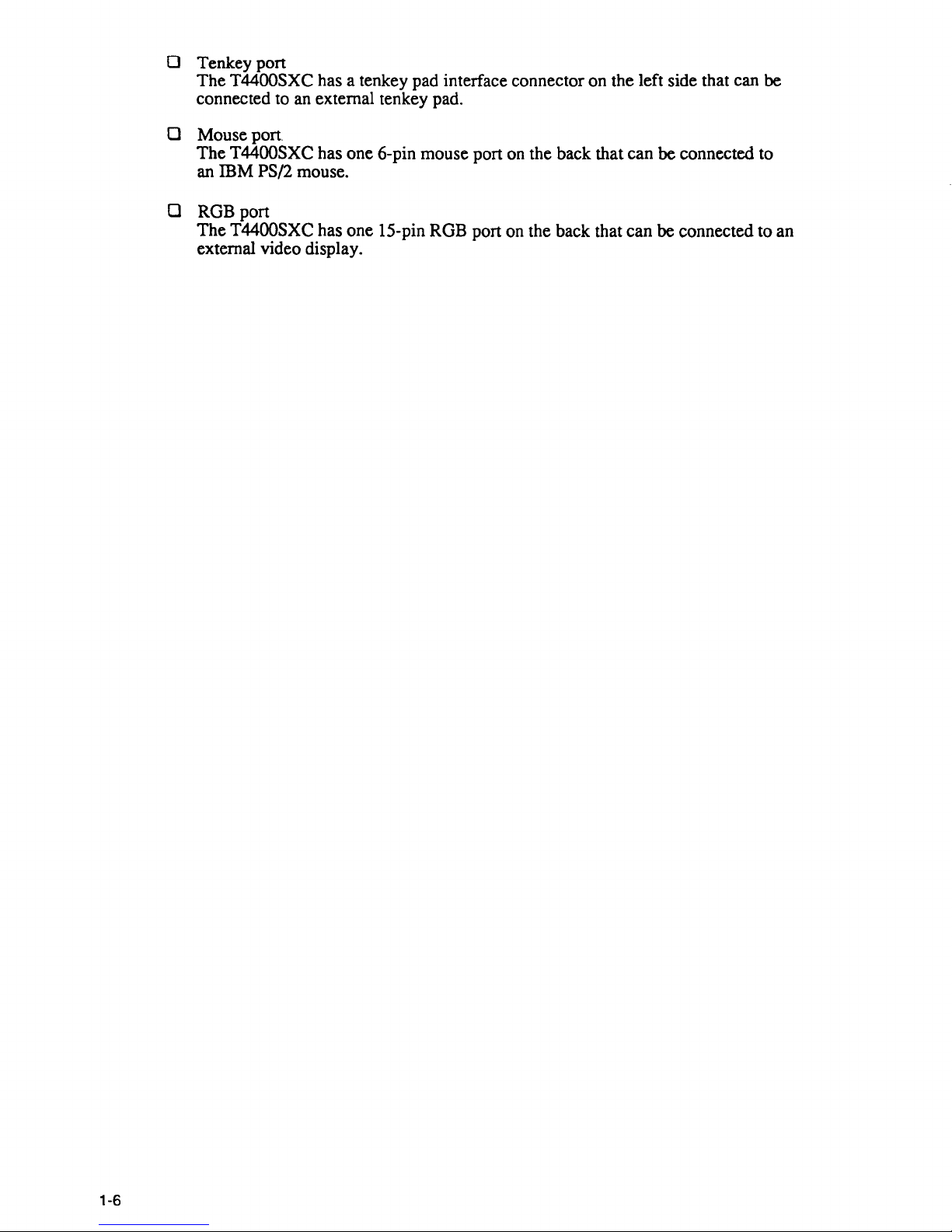
The T4400SXC Personal Computer is shown in figure 1-1. Its system configuration is shown
in figure 1-2.
Battery pack
Figure 1-1 T4400SXC system unit
PJ27
PJ19
PJ4
PJ5
PJ17
PJ18
PJ14
PJ9
Built-in modem
RS-232-C
PJ7 PJ25
PJ13
I--!--....I
P J12 I--+---I
PJ21----I
Sub
battery
PJ1
~--I
RTC
battery
PJ3
Figure 1-2 System unit configuration
1-7
.....
Co
"-':I
ciQ'
c
~
~
I
(M
t=
~
~
Co
;'
(JQ
r3
S
...--
LA23·17
----------~~~----------------------::::============:::::::::::g~~.1~7::~
SA19·0
SAUI·O
SOls.o
OSC
(20M)
CLKGEN
SOls.o
l.J
l
~=~-""l~
25M
44.9M
~
EXP
,
24M
28.322M
-=-,5:.0
A1'.M..5.
HOD
I/F
--
HOD
;
14.745M
25.175M
Dul
14.318M
l---'"
FY4H01
32.768K
RTC
BACK
UP
BATTERY
PVGA1
F
~
-.J
RAMV-
1:1->-=--
__
----1
PS/2
MOUSE
1r:i)8~~
KBC
-IEiIl TENKEY
RAMV-~
LJ
D
RAMV-~
:::>
80PIN
KB
L..-
___
----I
GA
~
I
ED
t----mIiD PANEL ONIOFF
SYS-
LA23·17
FY4LE2
CONT
FDD
CPU
A23.2
344PIN
SI
SERIAL
80486SXI
S015.0
'=>
T9901'1 P PRT/FDD
(EXP)
80486DXf-.-.,Q,31~
L
20BPIN
(*1) :
DMA
x 2
(25MHz)/
PIC
x 2
P23T
SA19.0
~
PIT
x 1
r-
-
SIOx2
~s
SPEAKER
FDC
x 1
L...-
__
..... I
VFO
x 1
-B-I-O-S-
....
I(
S015-O
~
~~KUP
ROM
L---I
r----
32K
x B
12BKxB
V
SA19-O
1.
r
~
.....
RAMV
II
~
+5V
(VCC)
............
-S-Y-S--...,L----J
uBUILT-INMOOEM
I
~
~5V
(RAMV)
+--OCIN
r
RAM
~
~TYPEE
.
-<~
~12V
+--MAINBATTER'
512KxB
L.
RAMV
T E
+--BACKUPBAn
MEMORY
JiJV
~
(DRAM
CARD)
t;
PS
031-0
~
-'
~~~1~
~r=S=P=V===-
__
.J
:!1
I-l
(1Q
N
a
....
I
Vl
1-3
~.
:r'
V)
~
nl
a-
00
-
~
g
~
-
~
nl
&.
9
~
~
~
a
=
....
-
0
=
......
...
-
::r
0
0
t")
t
~
~
8
_.
D)
en
(fQ
><
..,
(")
D)
V)
9
'<
V)
...
0
3
c:
~.
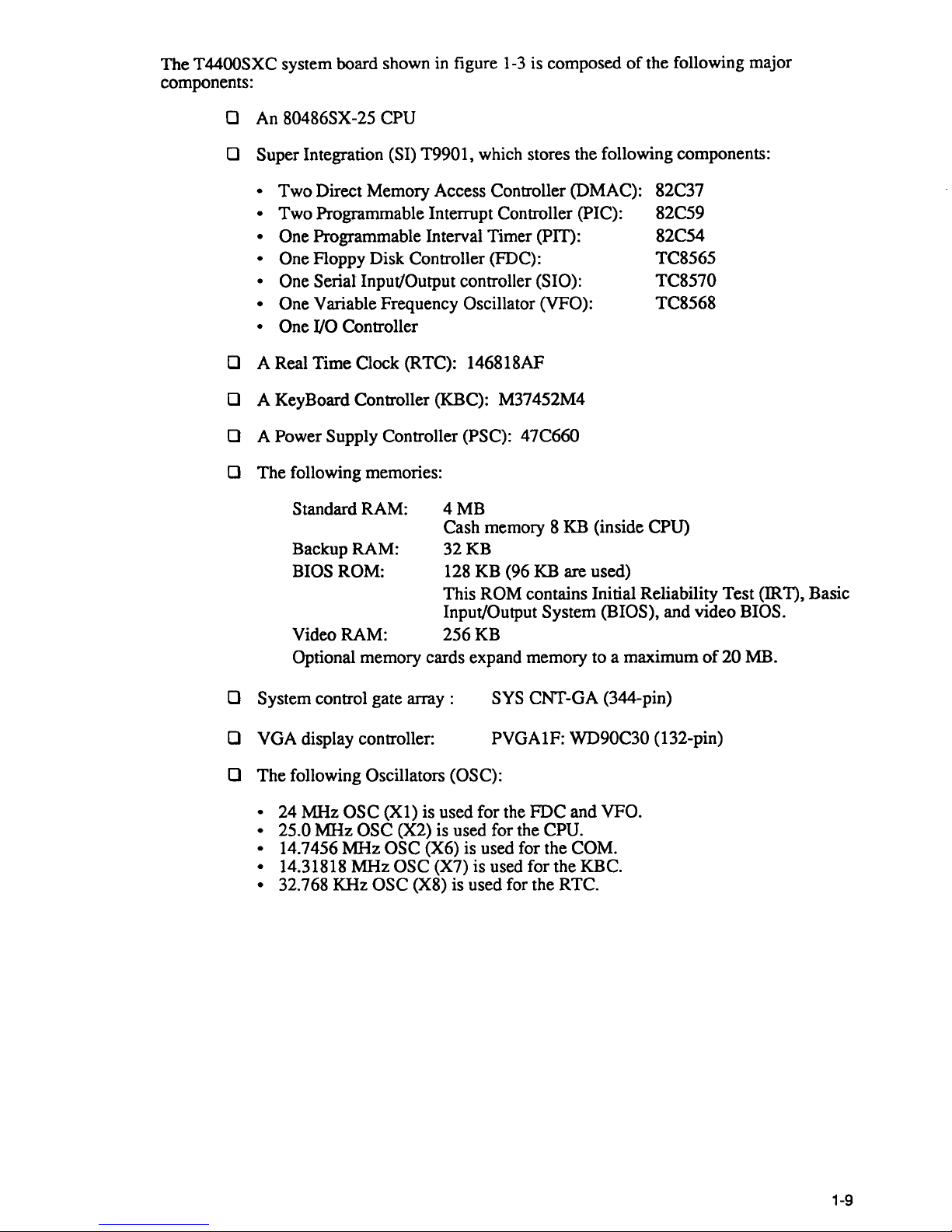
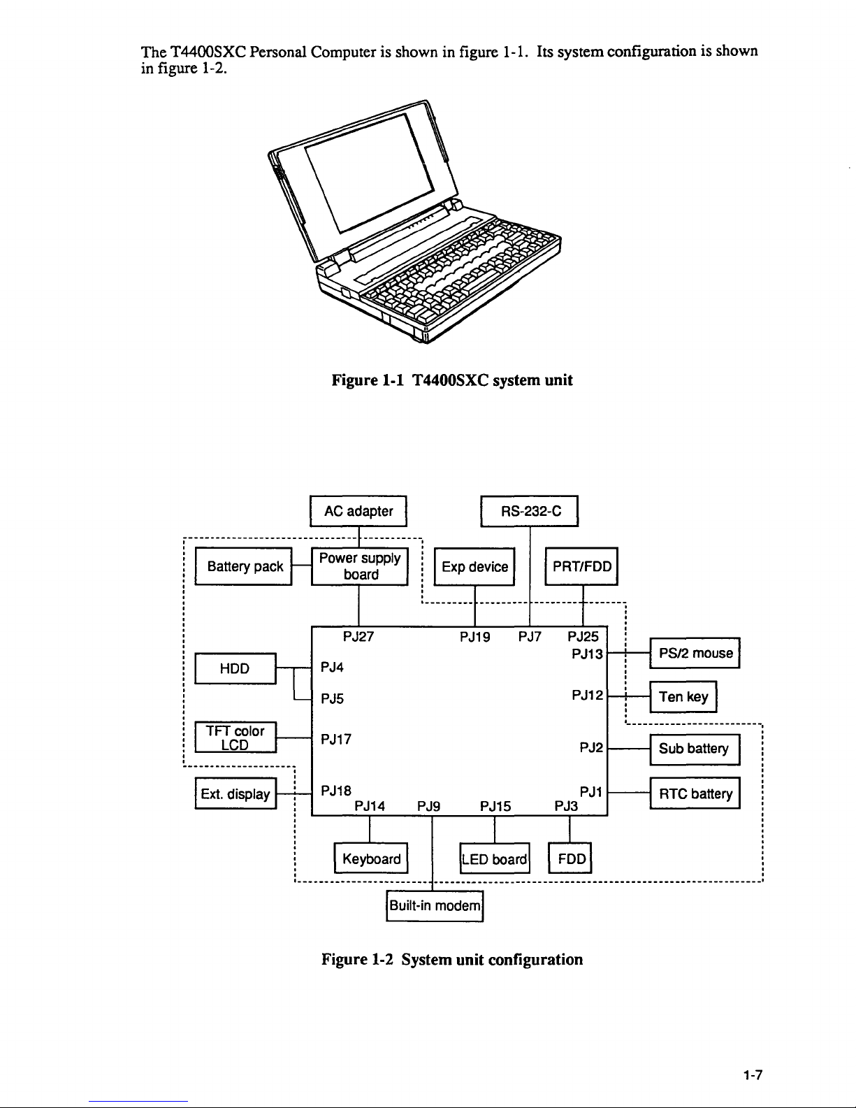
The T4400SXC system board shown in figure
1-3
is composed
of
the following major
components:
o An 80486SX-25 CPU
o Super Integration (SI) T9901, which stores the following components:
• Two Direct Memory Access Controller (DMAC):
• Two Programmable Interrupt Controller (PIC):
• One Programmable Interval Timer (PIT):
• One Floppy Disk Controller (FDC):
• One Serial Input/Output controller (SIO):
• One
Variable Frequency Oscillator (VFO):
• One I/O
Controller
o A Real Time Clock (RTC): 146818AF
o A KeyBoard Controller (KBC): M37452M4
o A Power Supply Controller (PSC): 47C660
o The following memories:
Standard RAM:
4MB
82C37
82C59
82C54
TC8565
TC8570
TC8568
Cash memory 8 KB (inside
CPU)
Backup RAM:
32KB
BIOS ROM: 128 KB (96 KB are used)
This
ROM contains Initial Reliability Test (IRT), Basic
Input/Output
System (BIOS), and video BIOS.
Video RAM:
256KB
Optional memory cards expand memory to a maximum
of
20 MB.
o System control gate array :
o VGA display controller:
SYS CNT-GA (344-pin)
PVGA1F:
WD90C30 (132-pin)
o The following Oscillators (OSC):
•
24 MHz OSC
(Xl)
is used for the FDC and VFO.
• 25.0
MHz OSC (X2) is used for the CPU.
•
14.7456 MHz OSC (X6) is used for the COM.
•
14.31818 MHz OSC (X7) is used for the KBC.
• 32.768 KHz OSC (X8) is used for the RTC.
1-9
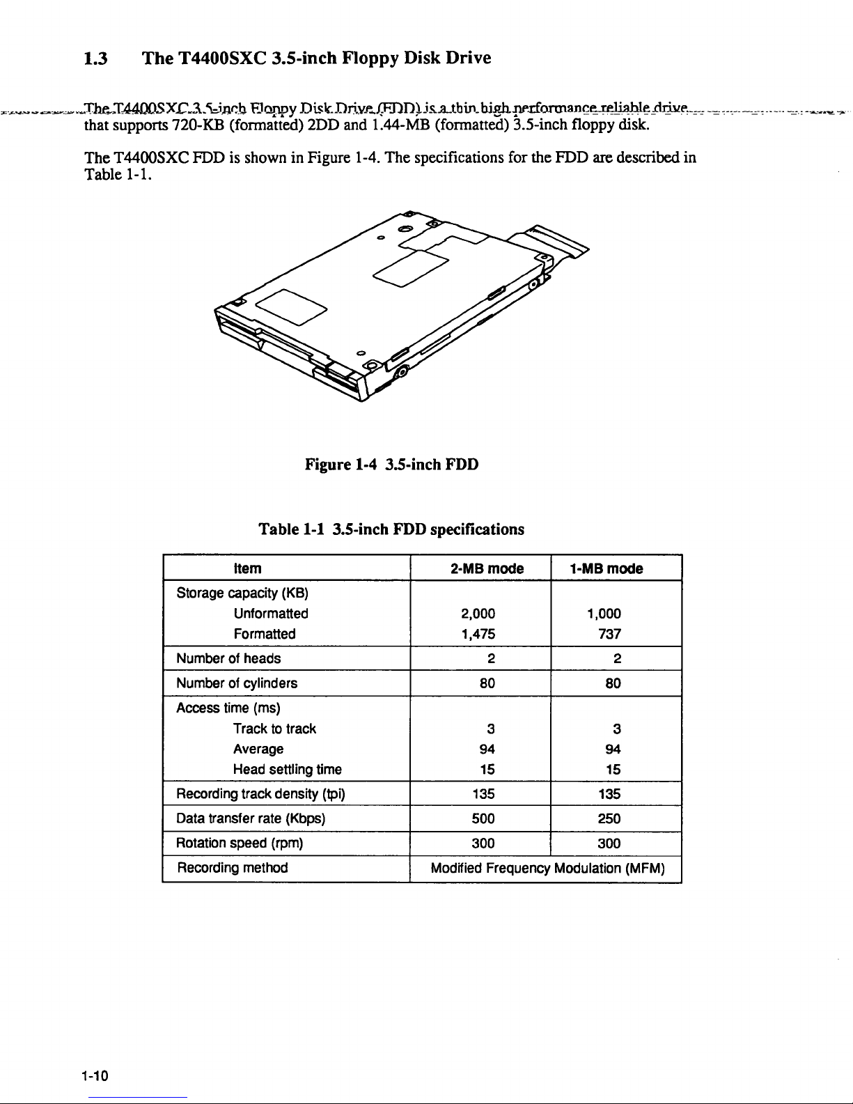
1.3
The
T4400SXC 3.S-inch Floppy Disk Drive
"'-.<-
....
~~~~_,_.~Tht-
..
I-4400SX..c~3._'\:.iJlr.]3,F.JappyDiskDrivJ"
...
f:FDn~js...a..tbin_bie.h-!1""rlOl1Jlan~ereli~hl~prjllf",_=-=-=c--_-----=--:------c=:-~~.",-
....
·
that supports 720-KB (fonnatted) 2DD and 1.44-MB (fonnatted) 3.5-inch floppy disk.
The
T4400SXC FDD is shown in Figure 1-4. The specifications for the FDD are described in
Table 1-1.
Figure 1-4 3.5-inch FDD
Table 1-1 3.5-inch FDD specifications
Item 2·MB mode 1-MB mode
Storage capacity (KB)
Unformatted
2,000 1,000
Formatted 1,475 737
Number of heads 2 2
Number of cylinders
80
80
Access time (ms)
Track
to
track
3
3
Average
94 94
Head settling time 15
15
Recording track density (tpi) 135
135
Data transfer rate (Kbps)
500
250
Rotation speed (rpm)
300 300
Recording method
Modified Frequency Modulation (MFM)
1-10
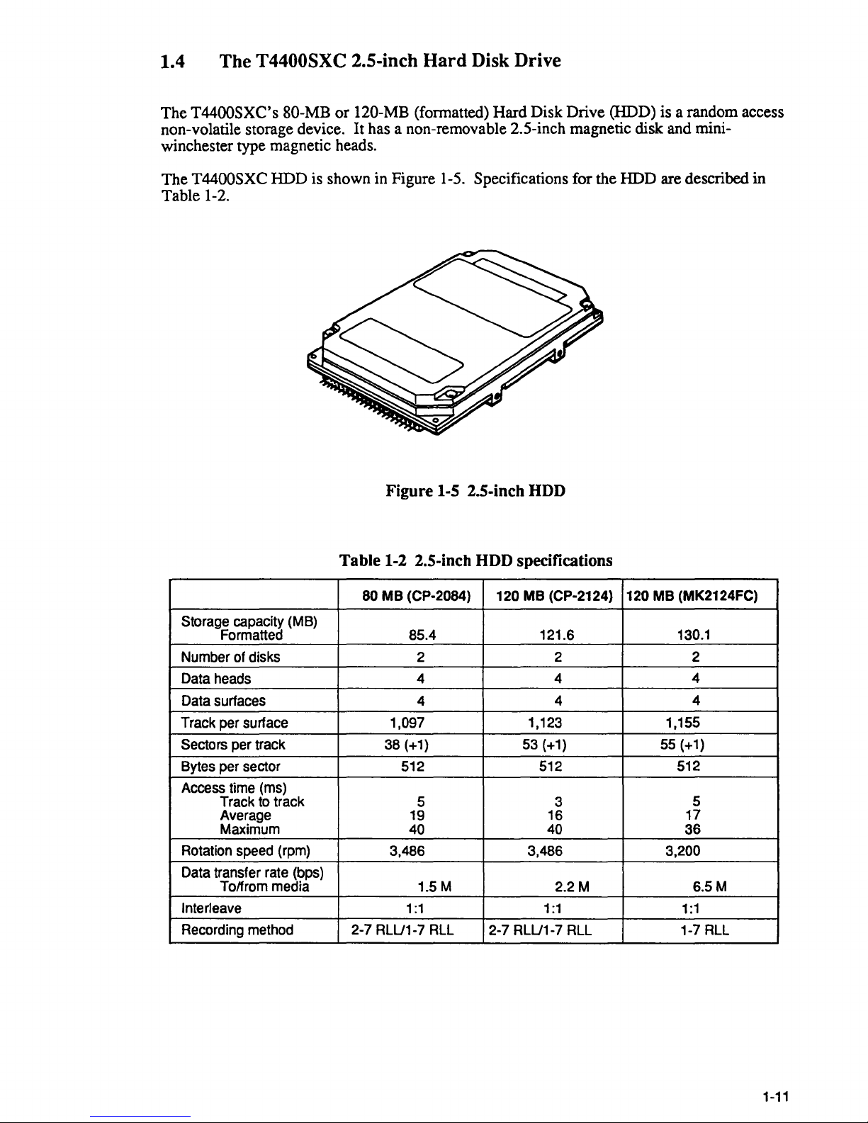
1.4 The T4400SXC 2.S-inch
Hard
Disk Drive
The T4400SXC's 80-MB
non-volatile storage device.
or
120-MB (formatted) Hard Disk Drive (HDD) is a random access
It
has a non-removable 2.5-inch magnetic disk and mini-
winchester type magnetic heads.
The
T4400SXC HDD is shown in Figure 1-5. Specifications for the HDD are described in
Table 1-2.
Figure
I-S 2.S-inch HDD
Table
Storage capacity (MB)
Formatted 85.4 121.6
Number of disks 2
Data heads
Data surfaces
Track per surface
Sectors per track
Bytes per sector 512 512
Access time (ms)
Track to track
Average 19
Maximum
Rotation speed (rpm) 3,486 3,486
Data transfer rate (bps)
Tolfrom media
Interleave
Recording method
1-2 2.S-inch HDD specifications
120
MB
80
MB
(CP-2084)
4 4
4 4
1,097 1,123 1,155
38 (+1)
5 3
40
1.5M
1:1
2-7 RLU1-7 RLL 2-7 RLU1-7 RLL 1-7 RLL
(CP-2124) 120
53 (+1) 55 (+1)
16
40
1:1 1:1
MB
(MK2124FC)
130.1
2 2
4
4
512
17
36
3,200
2.2M
5
6.5M
1-11
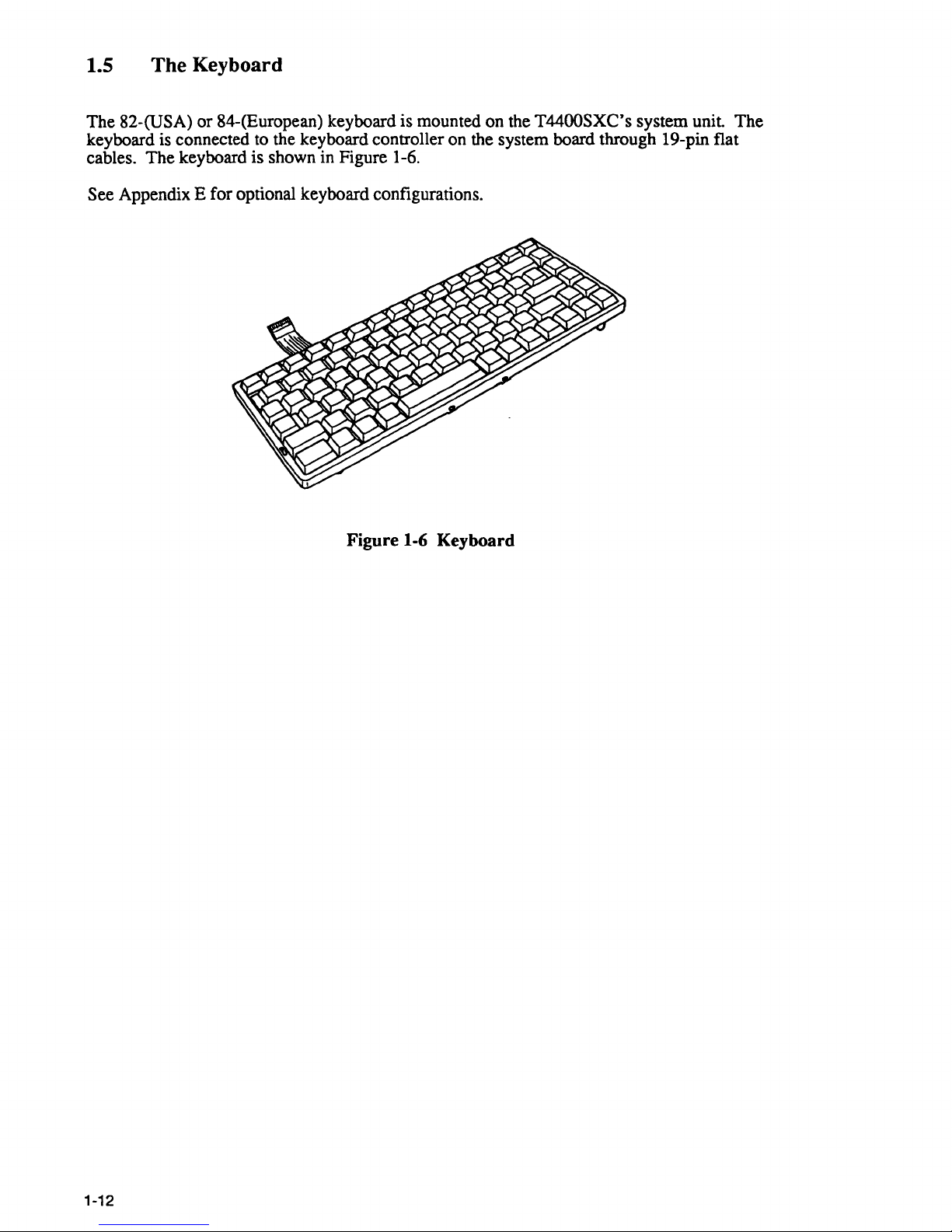
1.5 The Keyboard
The 82-(USA)
or
84-(European) keyboard is mounted on the T4400SXC's system
unit
The
keyboard is connected to the keyboard controller on the system board through 19-pin flat
cables. The keyboard is shown in Figure 1-6.
See Appendix E for optional keyboard configurations.
Figure 1-6 Keyboard
1-12
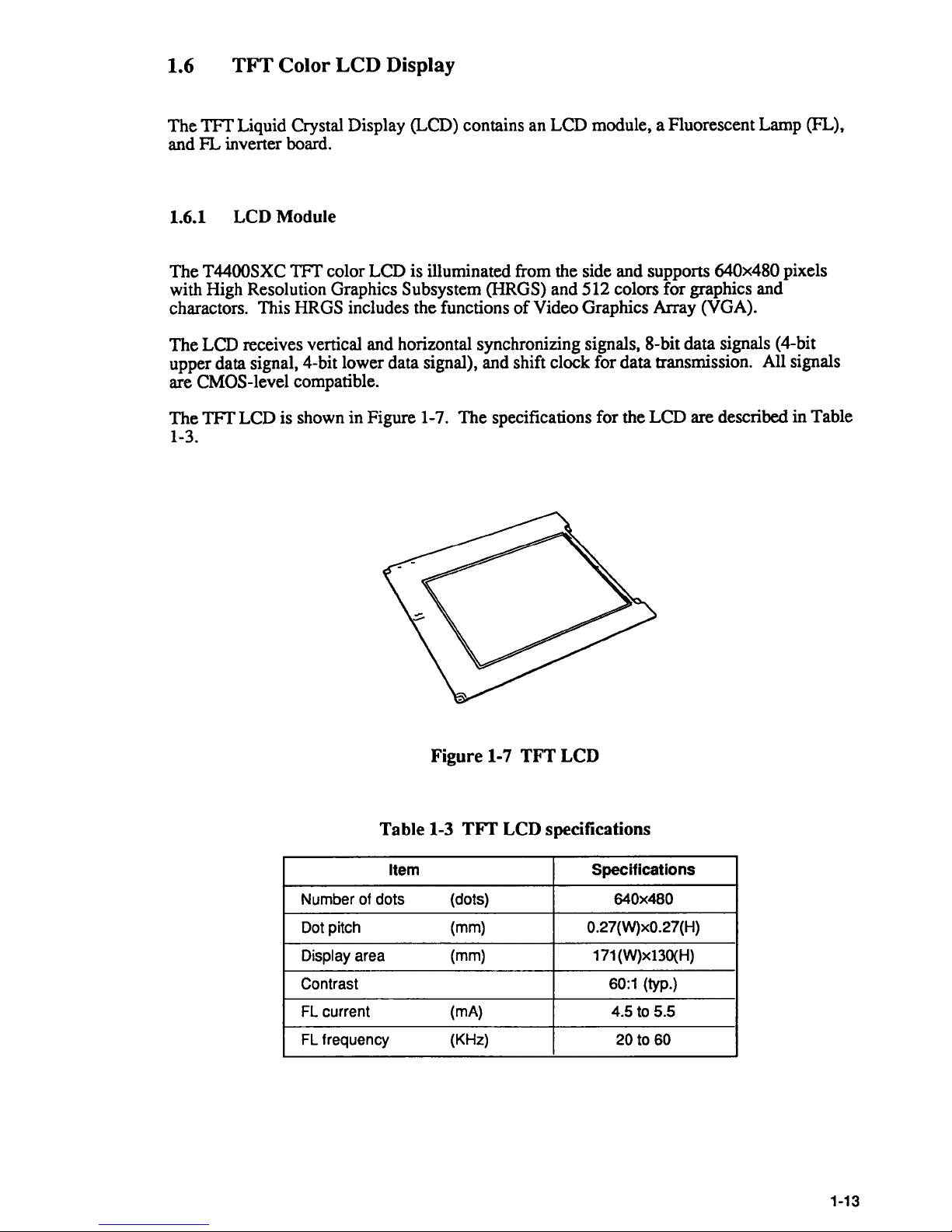
1.6
TFT
Color LCD Display
The
TFf
Liquid Crystal Display (LCD) contains an LCD module, a Fluorescent Lamp (FL),
and
FL
inverter board.
1.6.1 LCD Module
The T4400SXC
TFf
color LCD is illuminated from the side and supports 640x480 pixels
with High Resolution Graphics Subsystem (HRGS) and 512 colors for graphics and
charactors. This HRGS includes the functions
of
Video Graphics Array (VGA).
The LCD receives vertical and horizontal synchronizing signals, 8-bit data signals (4-bit
upper data signal, 4-bit lower data signal), and shift clock for data transmission. All signals
are CMOS-level compatible.
The
TFf
LCD is shown in Figure 1-7. The specifications for the LCD are described in Table
1-3.
Figure 1-7 TFT LCD
Table
1-3
TIT
LCD specifications
Item
Specifications
Number of dots
(dots)
640x480
Dot pitch (mm)
0.27(W)xO.27(H)
Display area
(mm) 171 (W)x13O(H)
Contrast 60:1 (typ.)
FL current (mA) 4.5 to 5.5
FL frequency (KHz)
20 to 60
1-13
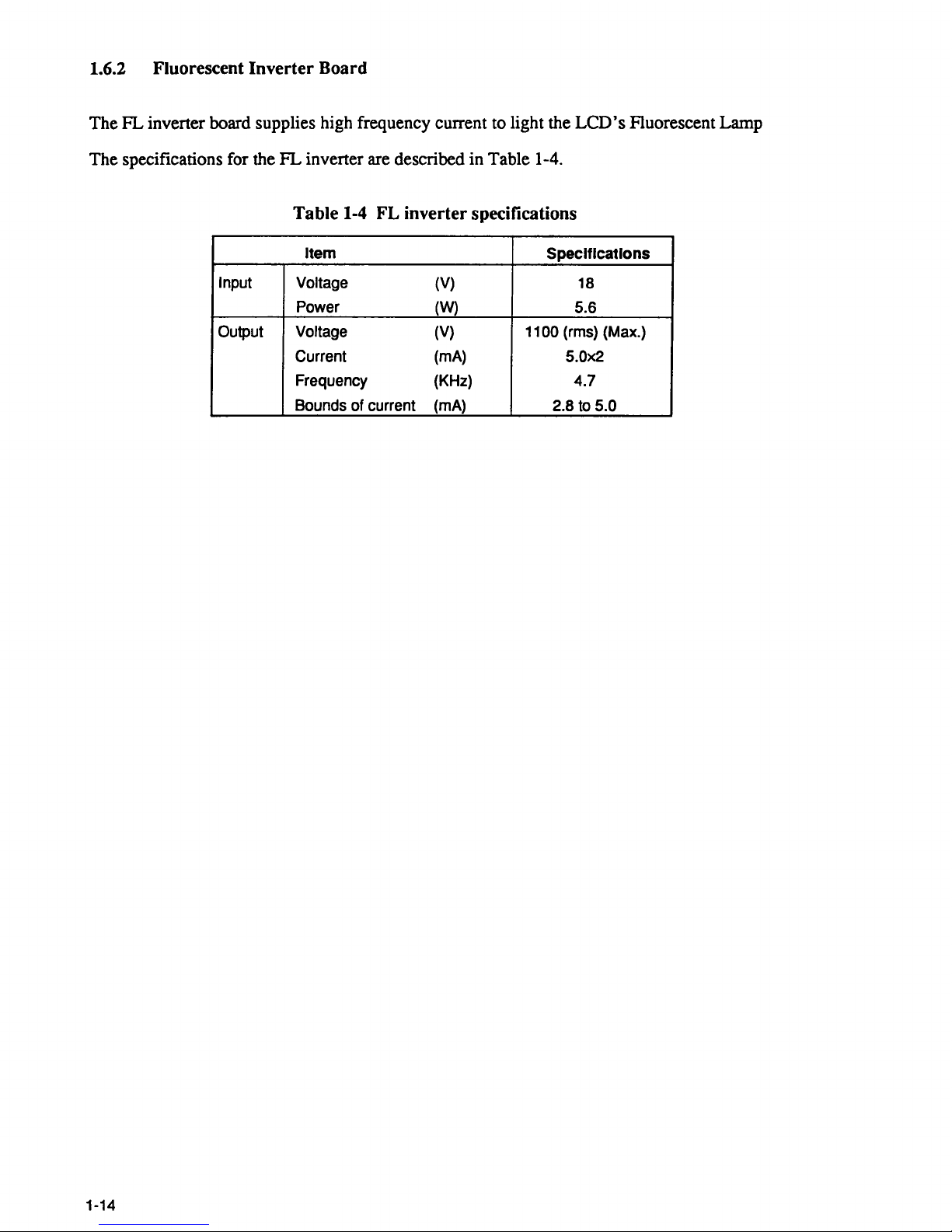
1.6.2 Fluorescent Inverter Board
The
FL
inverter board supplies high frequency current to light the
LCD's
Fluorescent Lamp
The specifications for the
FL
inverter are described in Table 1-4.
Table
1-4
FL inverter specifications
Item
Specifications
Input
Voltage
(V)
18
Power
(W) 5.6
Output
Voltage (V) 1100 (rrns) (Max.)
Current (rnA)
5.0x2
Frequency
(KHz)
4.7
Bounds of current (rnA)
2.8 to
5.0
1-14
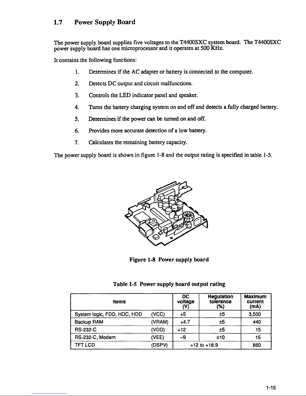
1.
7 Power Supply
The
power supply board supplies five voltages to the T4400SXC system board. The T4400SXC
power supply board has one microprocessor and
Board
it
operates at 500 KHz.
It contains the following functions:
1.
Determines
2.
Detects
3.
Controls the LED indicator panel and speaker.
if
the AC adapter
DC
output and circuit malfunctions.
or
battery is connected to the computer.
4. Turns the battery charging system on and
5. Determines
6.
Provides more accurate detection
7.
Calculates the remaining battery capacity.
The
power supply board is shown in figure 1-8 and the output rating is specified
if
the power can be turned on and off.
of
off
and detects a fully charged battery.
a low battery.
in
table 1-5.
System logic,
Backup
RS-232-C
RS-232-C, Modem
TFT LCD
RAM
Figure 1-8 Power supply board
Table
Items
FOO,
1-5
HOC, HOD (VCC)
Power supply board output rating
DC
voltage
(V) (%)
+5
(VRAM) +4.7
(VOO)
(VEE)
(OSPV)
+12
-9
+12 to +18.9
Regulation
tolerance
±5
±5 440
±5
±10
Maximum
current
(mA)
3,500
15
15
860
1-15

1-16
2.1 T4400SXC Troubleshooting
Pan
2 describes how to determine
causing the computer to malfunction.
1.
Power supply board
2.
System board
3. Floppy
Disk
Drive
4. Hard Disk Drive
5.
Keyboard
6.
Display
The
following tools are required to perform the T4400SXC troubleshooting steps.
1.
A T4400SXC Diagnostics Disk
2.
A Phillips head screwdriver (2 mm)
3.
An MS-DOS system disk
4. An 2DD
or
2HD
5. A Cleaning disk kit for the floppy disk drive troubleshooting
6.
A Printer port LED
7. An RS-232-C wraparound connector
8.
A Printer wraparound connector
9. A Multimeter
10.
External RGB monitor
11. External
5-1/4" floppy disk drive
if
a Field Replaceable Unit (FRU)
The
FRUs covered are:
in
formatted work disk for floppy disk drive testing
the T44QOSXC is
2-5
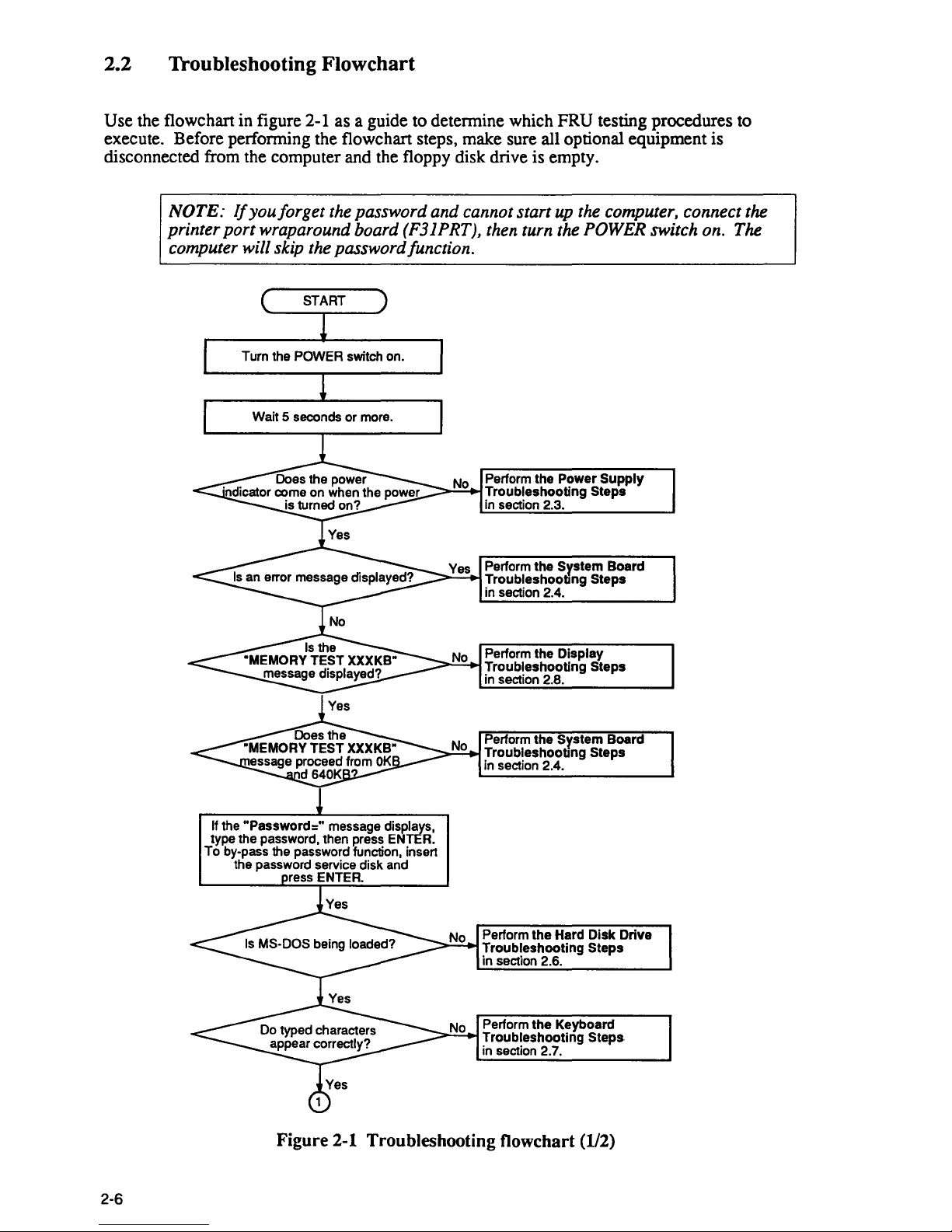
2.2 Troubleshooting Flowchart
Use the flowchart in figure 2-1 as a guide to detennine which FRU testing procedures to
execute. Before perfonning the flowchart steps, make sure all optional equipment is
disconnected from the computer and the floppy disk drive is empty.
2-6
NOTE:
Ifyou/orget
the password and cannot start up the computer, connect the
printer port wraparound board (F31PRT), then turn the
POWER switch on. The
computer will skip the password/unction.
Turn the POWER switch on.
Wait 5 seconds or more.
Perform the Power
Supply
~":"::=+I
Troubleshooting Steps
in
section 2.3.
Perform the
System Board
=::::"':"';-+1 Troubleshooting Steps
in section 2.4.
Perform the
Display
----.
Troubleshooting Steps
in
section 2.8.
Perform the
System Board
-----"-"""--' Troubleshooting Steps
in section 2.4.
If
the
"Password="
message displays,
type the password, then press ENTER.
To
by·pass the password function, insen
the password service disk and
ress ENTER.
Perform the Hard Disk Drive
Troubleshooting Steps
in section 2.6.
Perform the Keyboard
~>'-'-::,.j
Troubleshooting Steps
in section 2.7.
Figure
2-1
Troubleshooting flowchart (1/2)
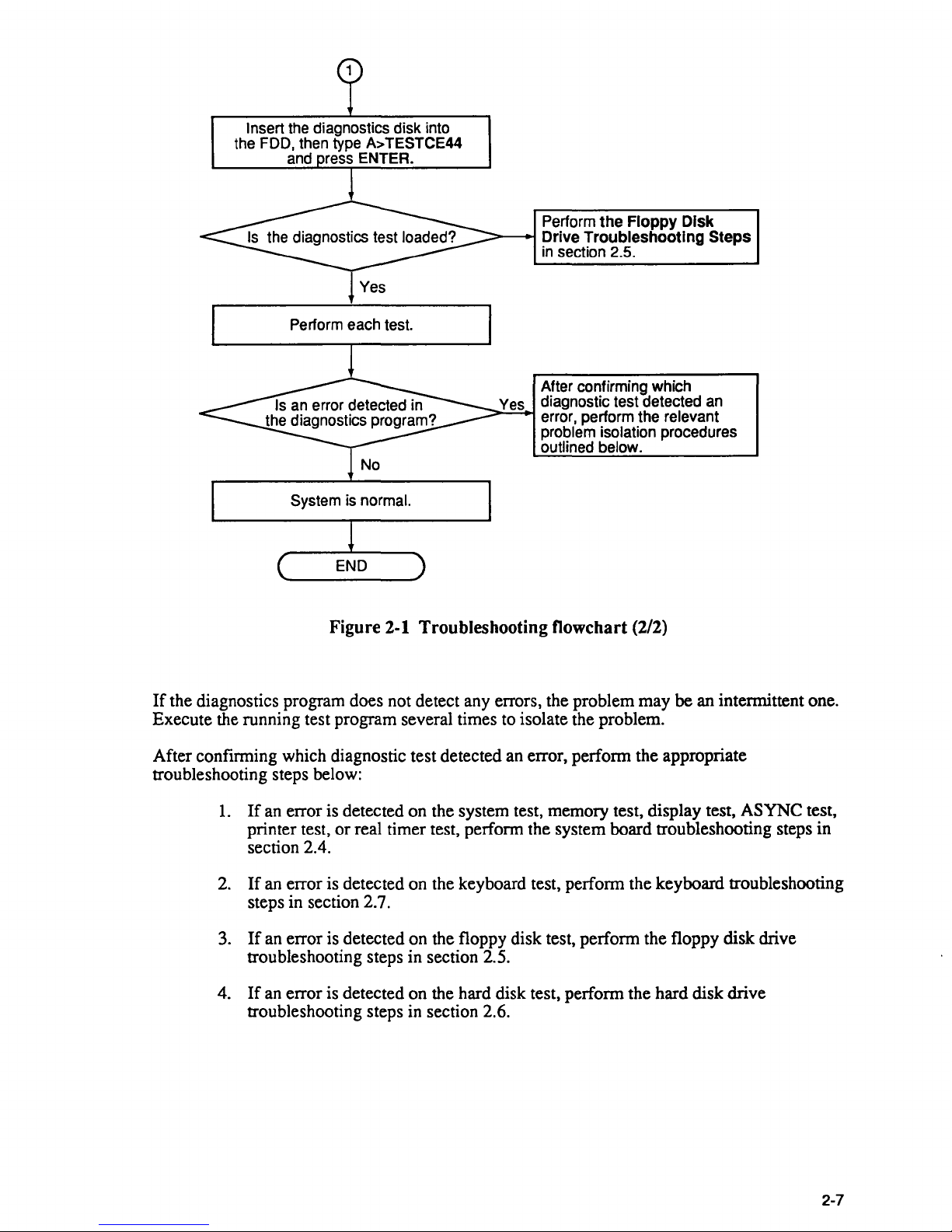
Insert the diagnostics disk into
the FDD, then type
A>
TESTCE44
and ress ENTER.
Perform each test.
System is normal.
Perform
the
Floppy
Disk
~-~
Drive
Troubleshooting
Steps
in
section 2.5.
After confirming which
Yes diagnostic test detected
an
error, perform the relevant
problem isolation procedures
outlined below.
Figure
2-1 Troubleshooting flowchart (2/2)
If
the diagnostics program does not detect any errors, the problem may be an intermittent one.
Execute the running test program several times to isolate the problem.
After confirming which diagnostic test detected an error, perform the appropriate
troubleshooting steps below:
1.
If
an
error is detected on the system test, memory test, display test, ASYNC test,
printer test, or real timer test, perform the system board troubleshooting steps in
section 2.4.
2.
If
an error is detected on the keyboard test, perform the keyboard troubleshooting
steps in section 2.7.
3.
If
an error is detected on the floppy disk test, perform the floppy disk drive
troubleshooting steps in section 2.5.
4.
If
an
error is detected on the hard disk test, perform the hard disk drive
troubleshooting steps in section 2.6.
2-7
2.3 Power Supply Board Troubleshooting Steps
The T4400SXC's power supply board controls many functions and components in the
T4400SXC. To determine
following checks as required. Start with step 1 and continue with the other steps
to.
if
the power supply board is functioning properly, perform the
if
you need
Step
Step
Step
1:
2:
3:
Battery Indicator Checklist
Power Supply Board Connector Checklist
System Board and Power Supply Board Replacement Checklist
Step 1 Battery Indicator Checklist
The T4400SXC's AC adapter convens AC power to
which charges
the back
off, the AC adapter charges the
The battery indicator displays the status
T4400SXC's batteries. The adapter connects to the DC IN
of
the computer. When the AC adapter is connected and the T4400SXC power is
T4400SXC's batteries.
of
the battery pack's charge and whether
AC adapter is connected and suppling power. The indicator labeled
when the AC adapter is charging the
The indicator labeled
"Battery" lights red
you connect the AC adapter to the
or
voltage is abnormal
the power supply malfunctions, this indicator blinks red
T4400SXC's battery pack.
if
power is supplied from the
T4400SXC and a wall outlet.
glow.
DC
and contains a charging circuit
If
21
V connector on
or
not the
"Battery"
AC
glows amber
adapter when
the AC adapter's output
or
does not
(1)
If
(2)
(3)
the battery indicator blinks red, see check
If
the battery indicator blinks yellow, see check 2.
If
the battery indicator does not glow, see check
1.
3.
Check 1 When tum on the power and battery indicator blinks once on a time on battery
operation, main battery will be fully discharged. Charge the main battery, then
again.
When the battery indicator informs the repeatedly blinking,
or
supply board,
status
of
power supply.
battery will be damaged. The repeatedly blinking is an error
AC
adapter, power
The battery indicator repeatedly informs the 4-bit status that is varied the blinking
of
interval with change
The battery indicator is put out two seconds at first, and
second with an interval
indicator glows 1 second, it shows the
second, it shows the
problem.
of
a half second in tum from bit 0 to bit
"1."
If
the battery indicator glows 0.5
"0."
it
lights one
3.
If
or
a half
the battery
try
2-8
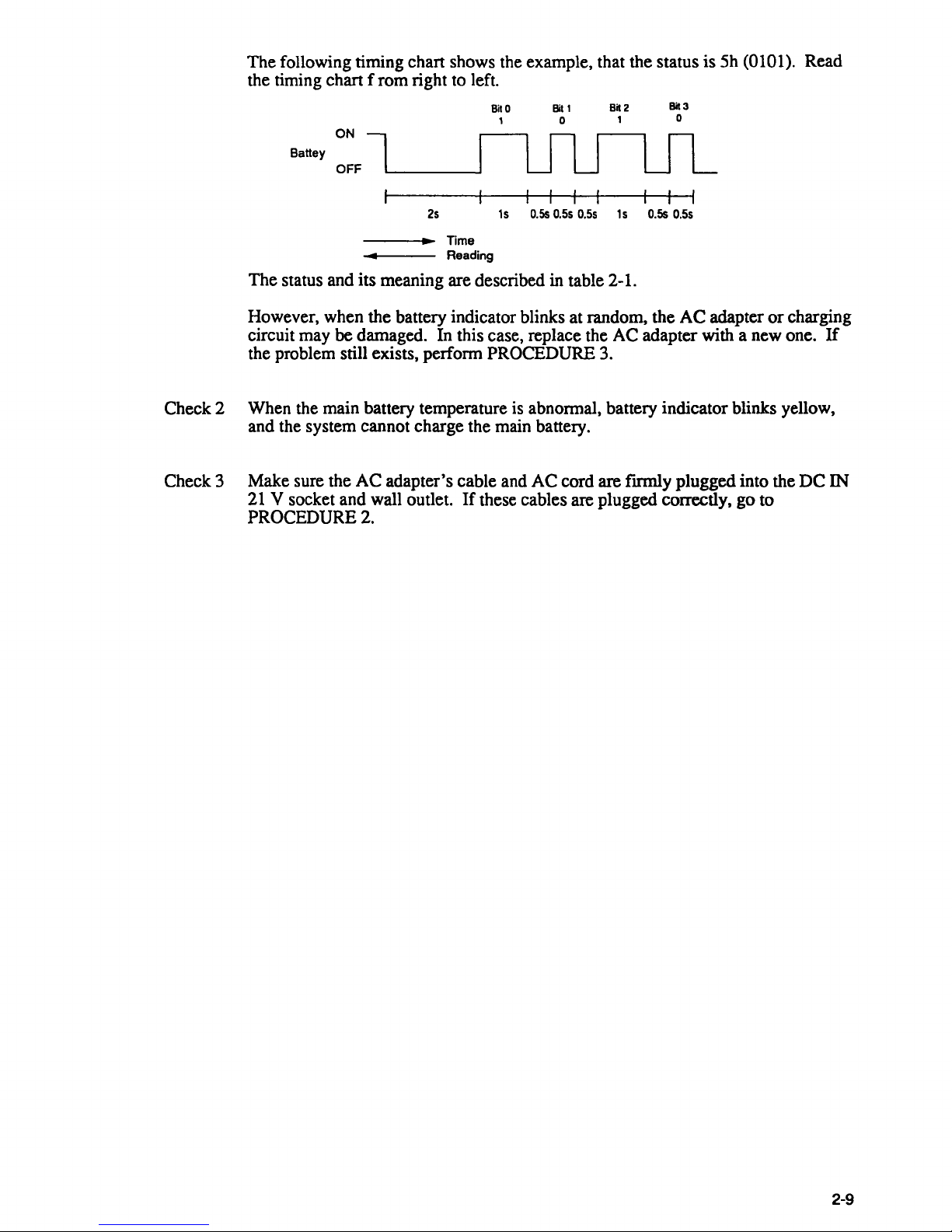
The
following timing chart shows the example, that the status
the timing chart f
Battey
ON
OFF
rom
right to left.
BilO
,
Bil'
o
Bk2
,
Bk3
o
is
5h
(0101). Read
The
status and
However, when
circuit may
be damaged. In this case, replace the
25
---i~~
• Reading
its
meaning are described in table 2-1.
the
battery indicator blinks at random,
Time
15
O.Ss
0.55
0.55
15
O.Ss
0.55
the
AC
adapter
AC
adapter with a new one.
or
charging
If
the problem still exists, perform PROCEDURE 3.
Check 2 When the main battery temperature is abnormal, battery indicator blinks yellow,
and the system cannot charge the main battery.
Check 3
Make
21
PROCEDURE
sure the
AC
adapter's
V socket and wall outlet.
2.
cable and
If
these cables are plugged correctly,
AC
cord are fIrmly
plugged
into the
go
to
DC
IN
2-9
Step 2 Power Supply Board Connector Checklist
_
____
The.
JlID'lecSllppJ}'-.iIDarcLis.
connector can become disconnected from the power supply board causing the T4400SXC to
To
malfunction.
check these connections, it is necessary to disassemble the T4400SXC.
Refer to part 4, Replacing T4400SXC Field Replaceable Units for more information about
how to disassemble the
When the T4400SXC is disassembled, make sure the following connections are secure and
the cables are not disconnected, pinched
connectors with new ones, connect any disconnected cables and assemble the
Execute the same procedures that were causing the T4400SXC to malfunction.
computer is still not functioning properly, go to step 3.
con
nec.te.dJo
T4400SXC.
.the-
syste.m.boaro.by.one.
or
broken. Replace any broken
fleyibk...cab1e-.-
or
damaged
T4400SXC.
-This cable ------------,--
If
the
------,,--.~.-=--=-=-~--=---
-
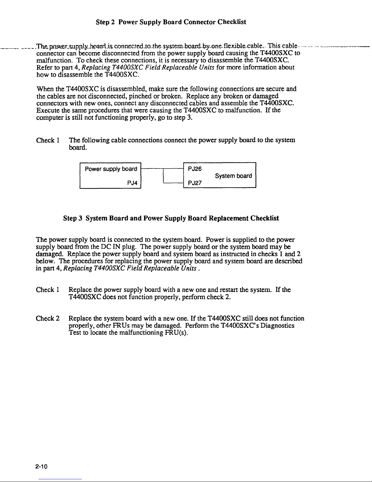
Check
1 The following cable connections connect the power supply board to the system
board.
Power supply board PJ26
PJ4 PJ27
I
System board
Step 3 System Board and Power Supply Board Replacement Checklist
The
power supply board is connected to the system board. Power is supplied to the power
DC
supply board from the
IN plug. The power supply board
damaged. Replace the power supply board and system board as instructed in checks 1 and 2
below. The procedures for replacing the power supply board and system board are described
in part 4,
Replacing T4400SXC Field Replaceable Units.
Check 1 Replace the power supply board with a new one and restart the system.
T4400SXC does not function properly, perform check 2.
or
the system board may be
If
the
Check 2 Replace the system board with a new one.
properly, other
FRUs may be damaged. Perform the T4400SXC's Diagnostics
Test to locate the malfunctioning FRU(s).
2-10
If
the T4400SXC still does not function
2.4 System Board Troubleshooting Steps
To determine
if
the system board is defective or not functioning properly, perform the
following set
of
steps beginning with step 1 and continue with the other steps as required.
Step
1:
Message Checklist
Step
2:
Printer Port LED Checklist
Step
3:
Diagnostic Test Program Execution Checklist
Step
4:
LED Board and RTC Battery Checklist
Step 5:
System Board Replacement Checklist
Step 1
Message Checklist
1.
Turn on the T4400SXC's power.
2.
If
the system is loaded normally, go to step
3.
3.
If
any
of
the following messages are displayed on the screen, press the
Fl
key to ex-
ecute the
SETUP program. Refer to part 3, Test and Diagnostics for more information
about the
T4400SXC's SETUP program.
****
Error
in
CMOS.
Bad
battery
****
Check
system.
Then
press
[Fl]
key
****
Error
in
CMOS.
Bad
check
sum
****
Check
system.
Then
press
[Fl]
key
****
Error
in
CMOS.
Bad
configuration
****
Check
system.
Then
press
[Fl]
key
· .
****
Error
in
CMOS.
Bad
memory
size
****
Check
system.
Then
press
[Fl]
key
· .
****
Error
in
CMOS.
Bad
HDD
type
****
Check
system.
Then
press
[Fl]
key
· .
****
Error
in
CMOS.
Bad
time
function
****
Check
system.
Then
press
[Fl]
key
· .
2-11
4.
If the following message is displayed
on
the screen, tum off the power. Wait five
seconds or more, and tum on the power again. If
the
same message reappears, go to
section 2.6,
Hard Disk Drive Troubleshooting Steps.
Insert
system
disk
in
drive
Press
any
key
when
ready
.....
5.
If
any
of
the following messages are displayed
on
the screen, go to step 4.
CPU
ERROR
SYSTEM
ROM
CHECK
SUM
ERROR
TIMER
CH.2
OUT
ERROR
PIT
ERROR
MEMORY
REFRESH
ERROR
FIRST
64KB
MEMORY
ERROR
RTC
ERROR
CRTC
ERROR
VRAM
ERROR
KBC
ERROR
SYSTEM
MEMORY
ERROR
SYSTEM
MEMORY
PARITY
ERROR
PROTECTED
MODE
ERROR
CPU
EXCEPTION
ERROR
EXTENDED
MEMORY
ERROR
EXTENDED
MEMORY
PARITY
ERROR
EMS
PAGE
REGISTER
ERROR
EXPANDED
MEMORY
ERROR
EXPANDED
MEMORY
PARITY
ERROR
DMA
PAGE
REGISTER
ERROR
DMAC
#1
ERROR
DMAC
#2
ERROR
PIC
#1
ERROR
PIC
M#2
ERROR
KEYBOARD
ERROR
KBC
ERROR
HDC
ERROR
HDD
#0
ERROR
HDD
#1
ERROR
NO
FDD
ERROR
FDC
ERROR
TIMER INTERRUPT
ERROR
RTC
UPDATE
ERROR
6.
If
none
of
these messages are displayed and you have a printer port LED, go to step
2.
2-12
Step 2
Printer
Port
LED Checklist
1.
Turn offthe power
to
the T4400SXC.
2.
Plug the printer port LED into the PRT/FDD port on the back
of
the T4400SXC.
3.
Watch the printer port LED, and turn on the power. The printer port LED will light
when the power switch is turned on.
4.
Read the LED status from left to right
as
a hexadecimal value.
5.
If
the final LED status matches any
of
the error status values in the table 2-1,
go
to step
4.
6.
If
the final LED status is FFH,
go
to step
3.
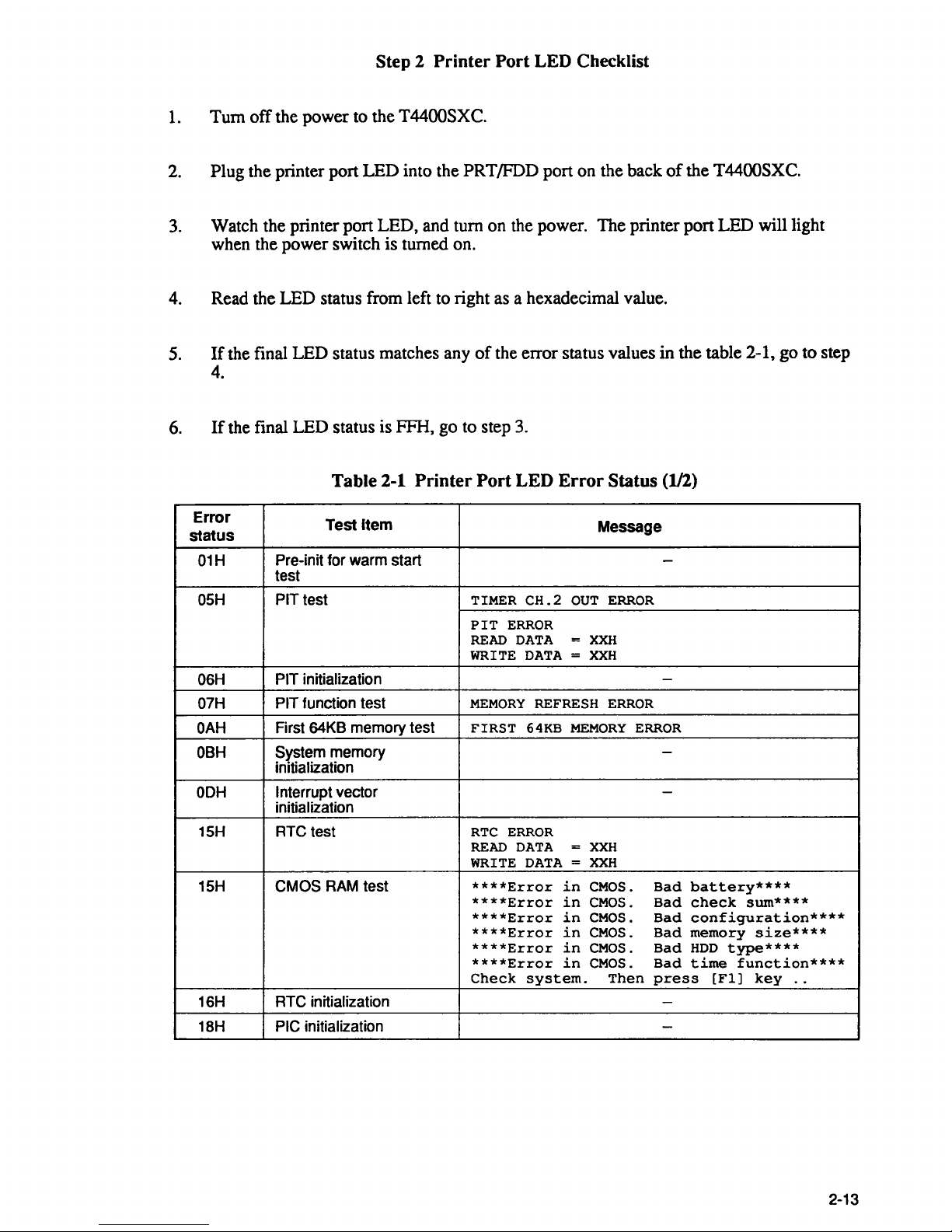
Table 2-1
Printer
Port
LED
Error
Status
(112)
Error
status
Test
Item
Message
01H
Pre-in it for warm start
-
test
05H
PIT
test TIMER
CH.2
OUT
ERROR
PIT
ERROR
READ
DATA
=
XXH
WRITE
DATA = XXH
06H
PIT initialization
-
07H PIT function test
MEMORY
REFRESH
ERROR
OAH
First 64KB memory test
FIRST
64KB
MEMORY
ERROR
OBH
System memory
-
initialization
OOH
Interrupt vector
-
initialization
15H RTC test
RTC
ERROR
READ
DATA = XXH
WRITE
DATA = XXH
15H CMOS
RAM
test
****Error
in
CMOS.
Bad
battery****
****Error
in
CMOS.
Bad
check
sum****
****Error
in
CMOS.
Bad
configuration****
****Error
in
CMOS.
Bad
memory
size****
****Error
in
CMOS.
Bad
HOD
type****
****Error
in
CMOS.
Bad
time
function****
Check
system.
Then
press
[Fl]
key
..
16H RTC initialization
-
18H PIC initialization
-
2-13
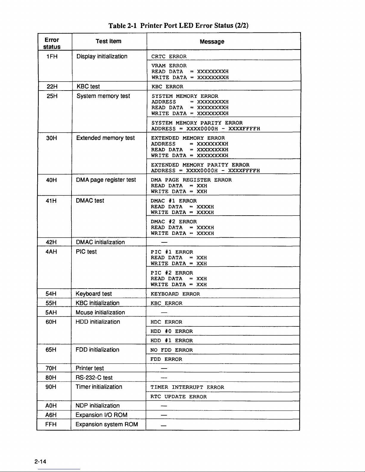
Table
2-1
Printer
Port
LED
Error
Status (2/2)
Error
status
Test
item
Message
1FH
Display
initialization
CRTC
ERROR
VRAM
ERROR
READ
DATA
=
XXXXXXXXH
WRITE
DATA = XXXXXXXXH
22H
KBC test
KBC
ERROR
25H
System memory test
SYSTEM
MEMORY
ERROR
ADDRESS
=
XXXXXXXXH
READ
DATA
=
XXXXXXXXH
WRITE
DATA = XXXXXXXXH
SYSTEM
MEMORY
PARITY
ERROR
ADDRESS = XXXXOOOOH -XXXXFFFFH
30H
Extended memory test
EXTENDED
MEMORY
ERROR
ADDRESS
=
XXXXXXXXH
READ
DATA = XXXXXXXXH
WRITE
DATA = XXXXXXXXH
EXTENDED
MEMORY
PARITY
ERROR
ADDRESS = XXXXOOOOH -XXXXFFFFH
40H
DMA page register test
DMA
PAGE
REGISTER
ERROR
READ
DATA
=
XXH
WRITE
DATA = XXH
41H
DMAC test
DMAC
#1
ERROR
READ
DATA
=
XXXXH
WRITE
DATA = XXXXH
DMAC
#2
ERROR
READ
DATA
=
XXXXH
WRITE
DATA = XXXXH
42H
DMAC initialization
-
4AH PIC test
PIC
U
ERROR
READ
DATA
=
XXH
WRITE
DATA
=
XXH
PIC
#2
ERROR
READ
DATA
=
XXH
WRITE
DATA = XXH
54H Keyboard test
KEYBOARD
ERROR
55H
KBC initialization
KBC
ERROR
5AH Mouse initialization
-
60H
HDD initialization
HDC
ERROR
HDD
#0
ERROR
HDD U ERROR
65H
FDD initialization
NO
FDD
ERROR
FDD
ERROR
70H Printer test
-
BOH
RS-232-C test
-
90H
Timer initialization TIMER
INTERRUPT
ERROR
RTC
UPDATE
ERROR
AOH
NDP initialization
-
A6H
Expansion
I/O ROM -
FFH Expansion system
ROM
-
2-14
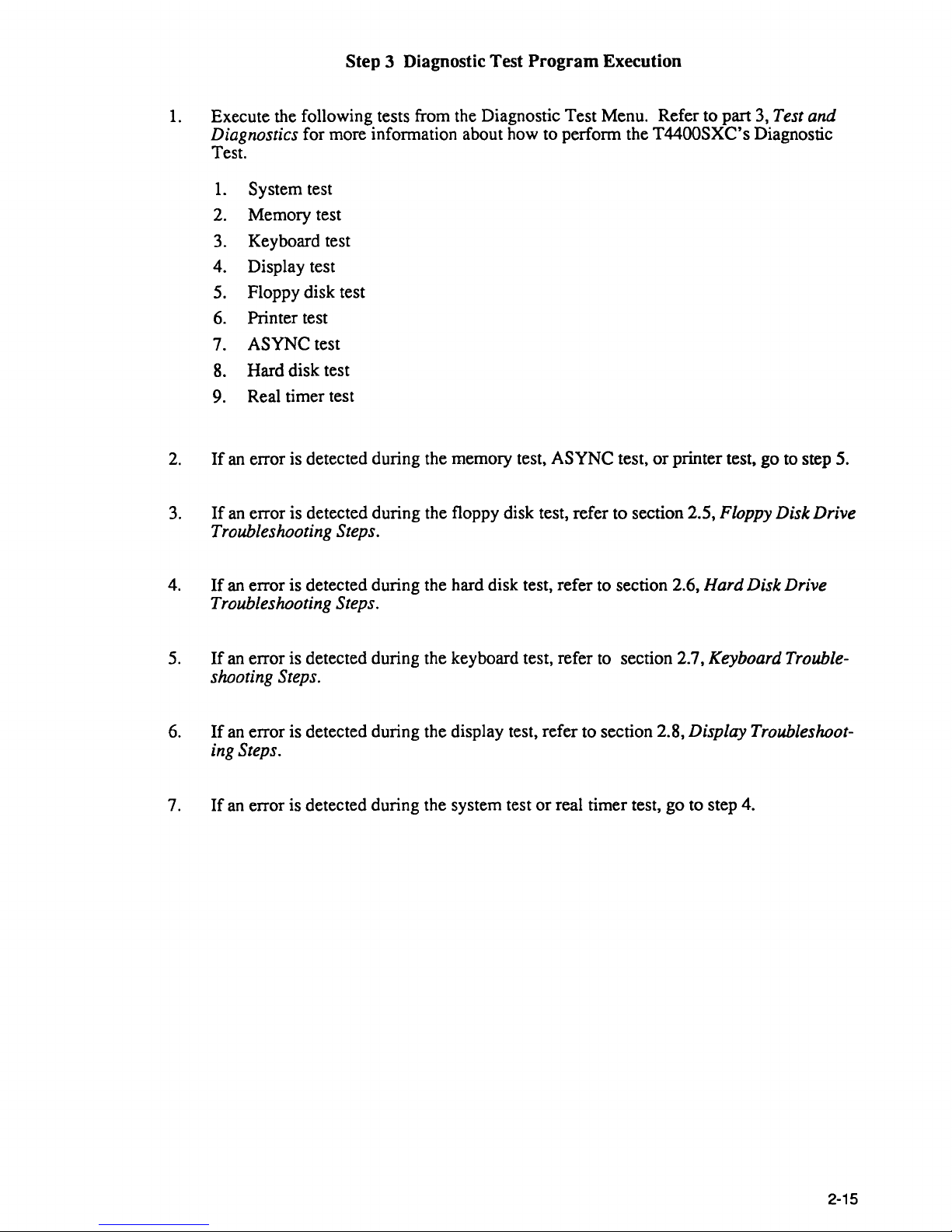
Step 3 Diagnostic Test
Program
Execution
1.
Execute the following tests from the Diagnostic Test Menu. Refer to part 3, Test and
Diagnostics
for more information about how to perform the
T4400SXC's
Diagnostic
Test.
1.
System test
2.
Memory test
3.
Keyboard test
4.
Display test
5.
Floppy disk test
6.
Printer test
7.
ASYNC
test
8.
Hard disk test
9.
Real timer test
2.
If
an
error is detected during the memory test,
ASYNC
test,
or
printer test, go to step 5.
3.
If
an
error is detected during the floppy disk test, refer to section 2.5, Floppy Disk Drive
Troubleshooting Steps.
4.
If
an error is detected during the hard disk test, refer to section 2.6, Hard Disk Drive
Troubleshooting Steps.
5.
If
an error is detected during the keyboard test, refer to section 2.7, Keyboard Trouble-
shooting Steps.
6.
If
an error is detected during the display test, refer to section 2.8, Display Troubleshoot-
ing Steps.
7.
If
an
error is detected during the system test
or
real timer test, go to step 4.
2-15
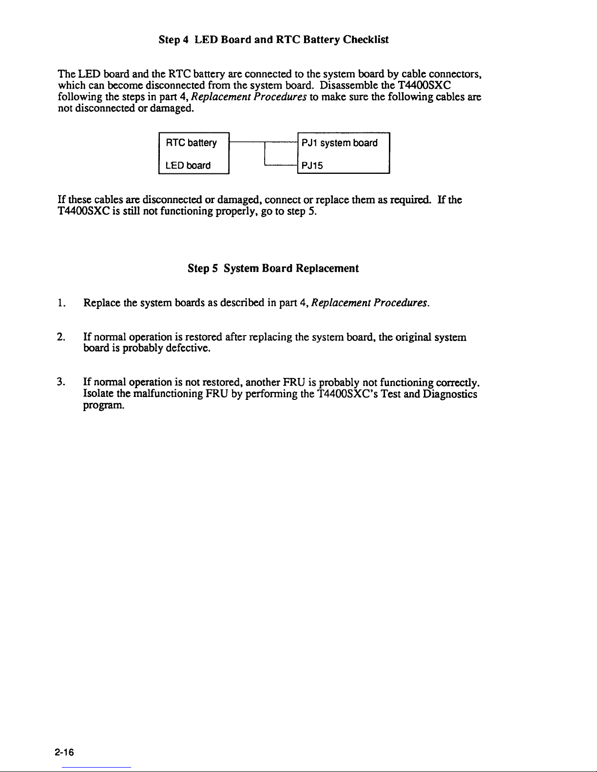
Step 4 LED Board
and
RTC
Battery Checklist
The LED board and the RTC battery are connected to the system board by cable connectors,
which can become disconnected from the system board. Disassemble the
T4400SXC
following the steps in part 4, Replacement Procedures
to
make sure the following cables are
not disconnected or damaged.
RTe battery
PJ1
system board
l
LED board PJ15
If
these cables are disconnected
or
damaged, connect or replace them as required.
If
the
T4400SXC is still not functioning properly, go to step
5.
Step 5 System Board Replacement
1.
Replace the system boards as described in part 4, Replacement Procedures.
2.
If
normal operation is restored after replacing the system board, the original system
board is probably defective.
3.
If
normal operation is not restored, another FRU is probably not functioning correctly.
2-16
Isolate the malfunctioning FRU by performing the T4400SXC's Test and Diagnostics
program.
2.5 Floppy Disk Drive Troubleshooting Steps
~~··~;~~=-
..
~~~~~.,:-:..-:-~----~---~-~~~~~~-,-,~~J~~~sn
rl·~ri!;;~M~-t~--33~~~~T4~.xc.r4nt2mr;J
l~.!:
..
~~p~~.&i~!~~~:c~~~~~~-.£i';:~"'~~u_So-~
functioning properly. Perfonn the steps below starting with Step 1 and continuing with the
other steps
as
required
Step
1:
FDD Head Cleaning Checklist
Step
2:
Extemal5-l/4"
FDD Checklist
Step
3:
Test Program Checklist
Step
4:
Connector Check and Replacement Checklist
Step 1 FDD Head Cleaning Checklist
FDD head cleaning is one
of
the menus on the test program.
After loading
MS-DOS, run the test program and then clean the FDD head using the cleaning
kit.
If
the FDD still does not function properly after cleaning, go to Step
3.
Detailed operation is described in part 3, "Test and Diagnostics."
If
the test program cannot be run, go to Step
2.
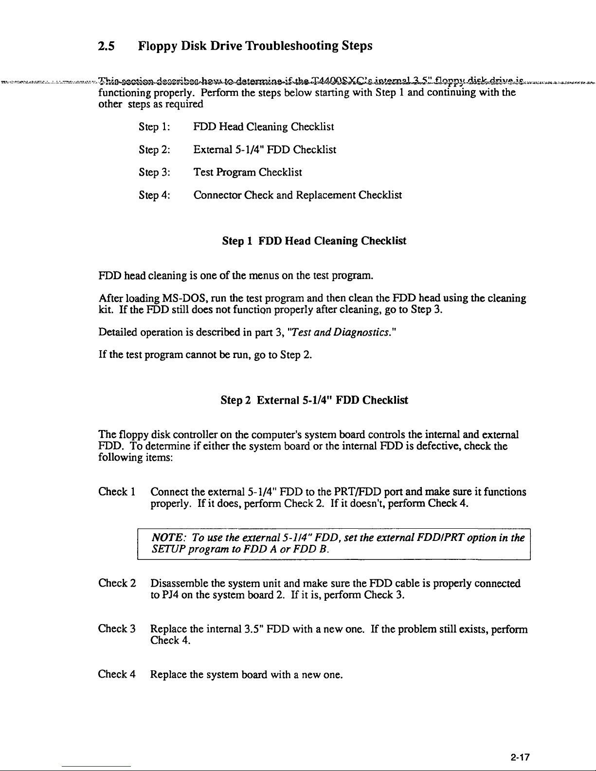
Step 2 External 5-1/4" FDD Checklist
The floppy disk controller on the computer's system board controls the internal and external
FDD. To determine
if
either the system board or the internal FDD is defective, check the
following items:
Check 1 Connect the external 5-1/4" FDD to the
PRT/FDD port and make sure
it
functions
properly.
If
it
does, perfonn Check
2.
If
it doesn't, perfonn Check 4.
NOTE: To use the external 5-114" FDD,
set
the external FDDIPRT option in the
SETUP program to FDD A
or
FDD B.
Check 2 Disassemble the system unit and make sure the FDD cable is properly connected
to
PJ4 on the system board
2.
If it is, perfonn Check
3.
Check 3 Replace the internal 3.5" FDD with a new one.
If
the problem still exists, perfonn
Check 4.
Check 4 Replace the system board with a new one.
2-17
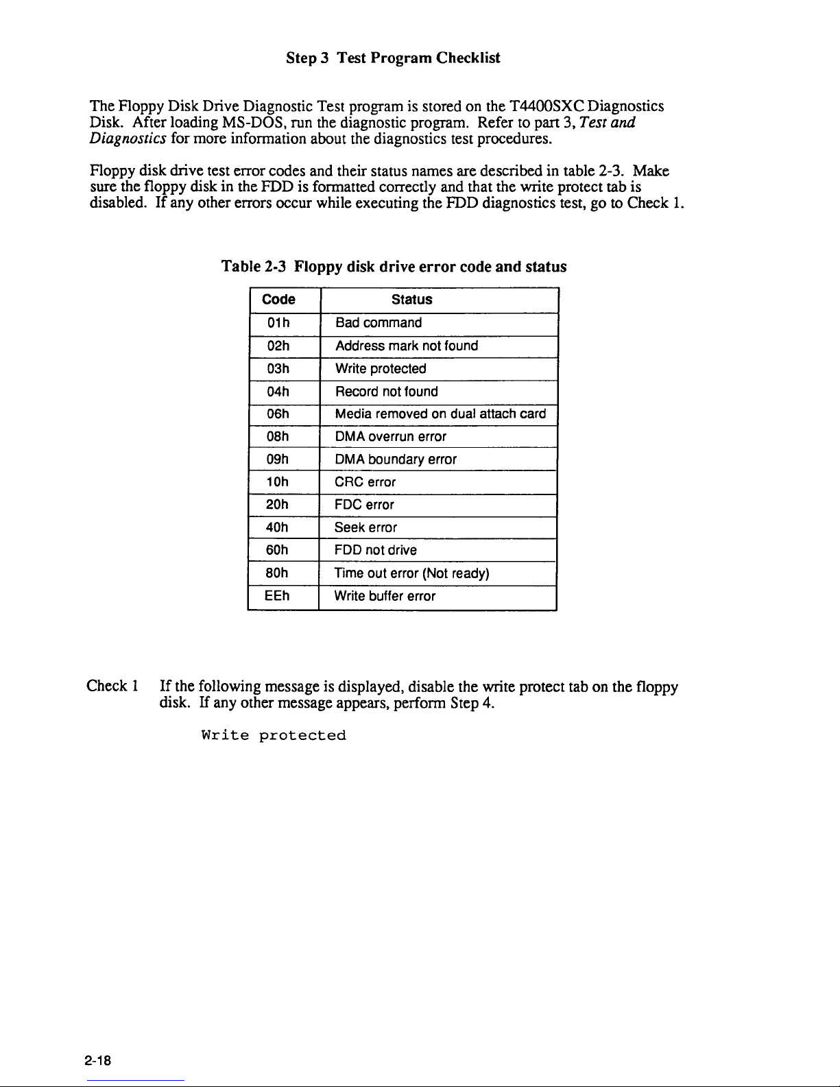
Step 3 Test Program Checklist
The Floppy Disk Drive Diagnostic Test program is stored on the T4400SXC Diagnostics
Disk. After loading
MS-DOS, run the diagnostic program. Refer to part 3, Test and
Diagnostics
for more information about the diagnostics test procedures.
Floppy disk drive test error codes and their status names are described in table 2-3. Make
sure the floppy disk in the FDD is formatted correctly and that the write protect tab is
disabled.
If
any other errors occur while executing the FDD diagnostics test, go to Check
1.
Table 2-3 Floppy disk drive
error
code
and
status
Code Status
01h
Bad command
02h Address mark not found
03h Write protected
04h
Record not found
06h Media removed on dual attach card
08h DMA overrun error
09h DMA boundary error
10h CRC error
20h
FDC error
40h Seek error
60h FDD not drive
80h
Time out error (Not ready)
EEh Write buffer error
Check 1
If
the following message is displayed, disable the write protect tab on the floppy
disk. If any other message appears, perform Step 4.
Write
protected
2-18
Step 4
Connector
Check
and
Replacement Checklist
The 3.5" Floppy Disk Drive is connected
to
the system unit by the FDD cable. This cable
may be disconnected from the system unit or damaged. Disassemble the
T4400SXC
following the steps described
in
part 4, Replacement Procedures to check the FDD's cable
and its connection to the system unit. Follow the checks below when replacing the FDD.
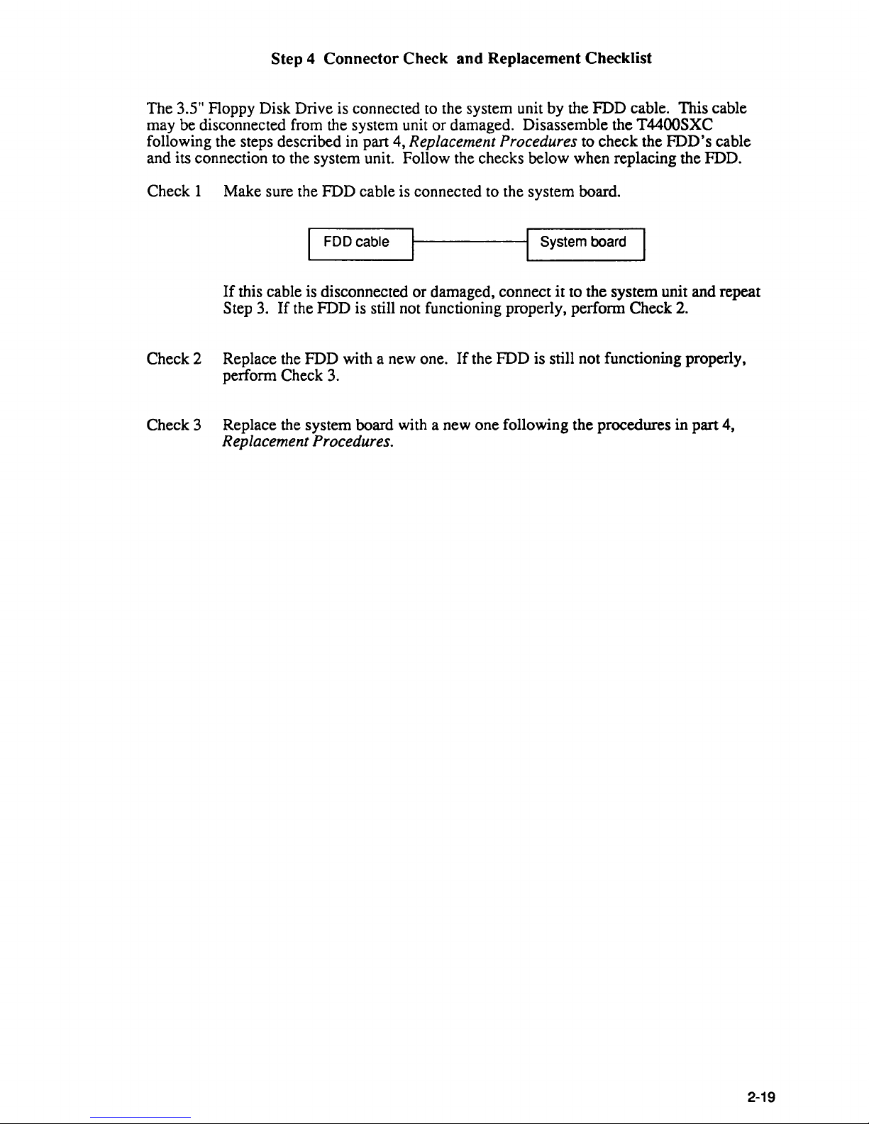
Check
1 Make sure the FDD cable is connected to the system board.
1 FDD cable
1---------11
System board
If
this cable is disconnected or damaged, connect it to the system unit and repeat
Step
3.
If
the FDD is still not functioning properly, perfonn Check
2.
Check 2 Replace the FDD with a new one.
If
the FDD is still not functioning properly,
perfonn Check
3.
Check 3 Replace the system board with a new one following the procedures in part 4,
Replacement Procedures.
2-19
2.6
Hard
Disk Drive Troubleshooting Steps
To detennine
if
the hard disk drive is functioning properly, follow the steps below starting
with
Step
1.
Continue with the other steps as required
Step
1:
Step
2:
Step
3:
Message Checklist
Fonnat Checklist
T~st
Program and Replacement Checklist
CA UTION: The contents
of
the hard disk will be erased when the HDD
troubleshooting steps are executed. Transfer the contents
of
the hard disk to
floppy disk using the MS-DOS
BACKUP command. Refer to the MS-DOS
manual
for
more information about how to perform the BACKUP command.
Step 1 Message Checklist
When the T4400SXC's HDD is not functioning properly, some
of
the following error
messages may appear on the display, start with Check 1 below and perfonn the other checks
as required.
Check 1
If
the following messages appear, perfonn Check
2.
If
the following messages do
not appear, perfonn Check
4.
HDC
ERROR
(After
5
seconds
this
message
will
disappear.)
or
HDD
#0
ERROR
(After
5
seconds
this
message
will
disappear.)
or
HDD
#1
ERROR
(After
5
seconds
this
message
will
disappear.)
Check 2
If
the following messages appear, perfonn Step
2.
If
the following messages do
not appear, perfonn Check
3.
2-20
Insert
system
disk
in
drive
Press
any
key
when
ready
.....
or
Non-System
disk
or
disk
error
Replace
and
press
any
key
when
ready.
Check 3 Using the MS-DOS system disk, install a system program on the hard disk using
the SYS command.
If
the following message appears on the display, the system program has been
transferred to the HDD. Restart the T4400SXC.
If
the error message still appears
perform Check 4.
System
transferred
If
an error message appears on the display, refer to the MS-DOS Manual for more
information about the error message and perform Check 4.
Check 4 The HDD is connected to the system board through an HDD interface cable and
power cable. These cables can become disconnected
or
damaged. Disassemble
the T4400SXC as described in part 4, Replacing
T4400SXC Field Replaceable
Units.
If
the HDD is not connected, connect it to the system board.
If
the HDD is
connected correctly to the system board, perform Step
2.
2-21
Step 2
Format
Checklist
The
T4400SXC's HDD is formatted using the low level format program and the MS-DOS
format
program. To format the HDD, start with Check 1 below and perform the other steps as
required.
Check 1 Using the
MS-DOS system disk, make a partition on the hard disk command using
the
FDISK command. Format the hard disk using the FORMAT
C:/S
to transfer
the system program to the HDD. If the following message appears on the display,
the HDD is
fermatted.
Format
complete
If
any other error messages appear on the display, refer to the MS-DOS Manual for
more information about the error message and perform Check
2.
Check 2 Using the T4400SXC test and diagnostic disk, format the HDD with a low level
format. Refer to part 3,
Test and Diagnostics for more information about the test
and diagnostic program.
2-22
If
the following message appears
on
the display, the HDD low level format is
complete. Make a partition and format the HDD using the
MS-DOS format
command.
Format
complete
If
you cannot format the HDD using the test and diagnostic program, perform Step
4.
 Loading...