

Toshiba T42#3F750XAXXN, T42#3F750FAXXN, T42#3F800XAXXN, T42#3F800FAXXN. User Manual
TOSHIBA
4200FA
UNINTERRUPTIBLE POWER SYSTEM
THREE-PHASE 75 / 80 kVA UPS
MANUFACTURED IN THE U.S.A.
Document Number: 56418-002
Date: December, 2004
USERS MANUAL

TOSHIBA
4200FA
THREE-PHASE 75/80 kVA
UNINTERRUPTIBL E POWER SYSTEM
OPERATION MANUAL
FOR MODELS
T42#3F750XAXXN, T42#3F750FAXXN,
T42#3F800XAXXN, T42#3F800FAXXN.
TOSHIBA
INTERNATIONAL CORPORATION
INDUSTRIAL DIVISION
13131 West Little York Rd., Houston, Texas 77041
TOSHIBA
IMPORTANT NOTICE
The Instructi ons cont ained in this manual are not int ended to cover all of
the details or vari ations in equipment or to provide for every possible
contingency to be m et in connec tion with installation, operation, or
maintenance. Should further information be required or should particular
problems arise which are not covered sufficiently the matter should be
referred to the local Toshiba sales office.
The contents of this instruction manual shall not become a part of or
modify any prior or exi sting equipment, commitment, or relationship. The
sales contract contains the entire obligat ion of Toshiba Internati onal
Corporation’s UPS Division. The warranty contained in the contract
between the parties is the sole warranty of Toshiba International
Corporation’s UPS Division, and any statement s cont ained herein do not
create new warranti es or modify the existing warranty.
Any Electrical or mechanical modifications to this equipment
without prior written consent of Toshiba International
Corporation will void all warranties and may void UL/CUL
listing. Unauthorized modifications may also result in
equipment damage, personal injury, or loss of life.
UNINTERRUPTIBLE POWER SYSTEM
If additional i nformation or technical assistance is required call Toshiba’s
Customer Serv ic e Depar tment toll free at 1-800-231-1412, or write to: Toshiba
International Corporation, 13131 W. Littl e Y or k Rd., Houston, TX 77041-9990.
Please complete the following inform ation f or your rec or ds. Unless otherwise
specified on the warranty c ar d, the warranty period for the UPS or UPS part is
36 months from the shipment date (see TIC bill of lading).
Unless otherwise speci fied on the warranty card, the warranty period for a
UPS battery is 24 months from the shipm ent date (see TIC bill of lading).
Keep this manual with the UPS equipment.
Job Number:
Model Number:
Serial Number:
Application:
Shipping Date:
Date of Installation:
Inspected By:
2
TOSHIBA
TABLE OF CONTENTS
IMPORTANT NOTICE.......................................................................................................2
TABLE OF CONTENTS....................................................................................................3
Purpose and Scope of Manual .......................................................................................5
Contacting Toshiba’ s Customer Support Center..........................................................5
GENERAL SAFETY INSTRUCTIONS..............................................................................6
EQUIPMENT WARNING LABELS....................................................................................8
IMPORTANT SAFETY INSTRUCTIONS.........................................................................10
1.0 Product Description.............................................................................................13
1.1 Theory of Operati on ...................................................................................................................13
1.2 Application and use.................................................................................................................... 13
1.3 Power Backup............................................................................................................................13
1.4 Power Conditioning....................................................................................................................13
2.0 Unpacking/Inspection/Storage/Disposal............................................................14
2.1 Unpacking the new UPS equipment:...........................................................................................14
2.2 Inspection of the new UPS equipment ........................................................................................15
2.3 Storage of UPS equipm ent.........................................................................................................15
2.4 Disposal.....................................................................................................................................15
3.0 Precautions...........................................................................................................16
3.1 Installation Precautions................................................................................................................16
3.2 Pre-start Precautions..................................................................................................................17
3.3 Ope r a ting P re c a u t io n s................................................................................................................17
4.0 UPS Connections .................................................................................................18
4.1 UPS Power and Control Connections........................................................................................ 18
4.1.1...Recommended Wir e Size and Tightening Torque For UPS Input and Output Terminals.........19
4.1.2...Power Connection Cable Routing..........................................................................................20
4.1.3...Dual Input Configuration........................................................................................................28
4.2 Control Circ uit and Ex ternal Battery Interface Connections .........................................................29
4.2.1...Recommended Wir e Size and Tightening Torque UPS Control and B att er y Interface.............29
4.3 Communication Interface............................................................................................................30
4.3.1...Remote Contact....................................................................................................................30
4.3.2...RS-232C............................................................................................................................... 31
4.3.3...UPS Shutdown (v i a RS-232C)...............................................................................................31
5.0 Specifications.......................................................................................................32
5.1 Specifications – 4200FA 75kVA with Internal T r ansformer..........................................................32
5.2 Specifications – 4200FA 75kVA without Inter nal Transformer .....................................................33
5.3 Specifications – 4200FA 80kVA with Internal T r ansformer..........................................................34
5.4 Specifications – 4200FA 80kVA without Inter nal Transformer .....................................................35
6.0 Operating the UPS................................................................................................36
6.1 Ope r a ting th e UPS..................................................................................................................... 36
6.1.1...AC Input Mode (normal operation).........................................................................................36
6.1.2...Circuit-bypass Mode..............................................................................................................36
6.1.3...Battery Back u p Mod e............................................................................................................37
6.2 Battery Backup Time and Discharge Process .............................................................................38
6.3 Battery Low Voltage T ol er anc es .................................................................................................38
6.4 Battery Recharging.....................................................................................................................39
6.5 Front Panel Layout (All Units).....................................................................................................40
6.6 EPO ( Emergen cy P o wer Off) Function .......................................................................................41
6.7 Au d ible Ala rm Functions.............................................................................................................41
6.8 Light Emitting Di ode ( LE D) Functions......................................................................................... 42
6.8.1...Light Emitting Di ode ( LE D) System S tatus.............................................................................42
6.9 Liquid Crystal Display (LCD) Functions.......................................................................................43
3
TOSHIBA
6.9.1...Line-1 System Messages...................................................................................................... 43
6.9.2...Line-2 System Fault Messages ............................................................................................. 43
6.9.3...Line-3 System Messages...................................................................................................... 43
6.9.4...Line-4 System Messages...................................................................................................... 44
6.10 Initial Battery Charge ................................................................................................................. 45
6.11 S tart-up Procedure..................................................................................................................... 46
6.12 S hutdown Procedure..................................................................................................................47
6.13 K ey pad Overview....................................................................................................................... 48
6.14 Key Functions............................................................................................................................49
6.14.1.MONI.................................................................................................................................... 49
6.14.2.IN..........................................................................................................................................49
6.14.3.OUT...................................................................................................................................... 49
6.14.4.BATT Key............................................................................................................................. 50
6.14.5.MENU, F1, ENTER, UP, & DOWN Keys...............................................................................50
6.14.6.BATT TEST Key...................................................................................................................50
6.14.7.BUZZ STOP Key...................................................................................................................51
6.14.8.RESET Key..........................................................................................................................51
6.15 M enu Data Screens................................................................................................................... 52
6.15.1. Setti ngs for Calendar and Clock............................................................................................52
6.15.2.Adjusting Buzzer Volume......................................................................................................52
6.15.3.Settings for Display Duration................................................................................................. 53
6.15.4.Run Switch Select ................................................................................................................. 53
6.15.5.Serial Com Station Address..................................................................................................54
6.15.6. Output Voltage Adjustment ................................................................................................... 54
6.15.7. Charge Mode Select ............................................................................................................. 55
6.15.8.Reset to Default Settings.......................................................................................................55
6.16 Overload Operation....................................................................................................................56
6.17 Backup History & Faul t History...................................................................................................57
7.0 UPS Protection System........................................................................................59
7.1 System Protection Features.......................................................................................................59
7.2 System Protection Functi ons...................................................................................................... 59
8.0 Preventive and Scheduled Maintenance / Part Replacement............................60
8.1 Preventiv e Maintenance............................................................................................................. 60
8.2 Parts Replacement....................................................................................................................60
9.0 External Dimensions / Shipping Weights ...........................................................61
9.1 External Dimensions..................................................................................................................61
9.2 Shipping Dimensions.................................................................................................................62
9.3 Sh ipping Weigh ts....................................................................................................................... 62
4
TOSHIBA
Purpose and Scope of Manual
This manual provides information on how to safely i nstall, operate, and maint ain y our TIC power electronics
product. Thi s manual includes a section on General Safety Instructions that describes the warning label s
and symbols that are used throughout the manual. Read the m anual c om pletely before installing,
operating, or performing maintenance on t his equi pment.
This manual and the acc om panyi ng dr awings should be considered a permanent part of the equipment and
should be readil y av ailable for reference and review. Dimensions shown in the manual ar e in m etric and/or
the English equivalent.
Toshiba Inter national Corporation r eserves the right, without prior notice, to update inform ation, make
product changes, or t o discontinue any product or service identified in this publ ic ation.
TOSHIBA is a registered t r adem ar k of the Toshiba Corporation. All other product or trade refer enc es
appearing in this manual are registered tr adem arks of their respective owners.
Toshiba International Corporation (TIC) shall not be liable for technical or editorial omissions or
mistakes in this manual. Nor shall it be liable for incidental o r consequential damages result ing
from the use of information contained in this manual.
This manual is copyri ghted. No part of this manual may be photocopied or reproduced in any form without
the prior written consent of Toshiba Inter national Corporation.
© Copyright 2004 Toshi ba International Corporation.
All rights reserved.
Printed in the U.S.A.
Contacting Toshiba’s Customer Support Center
Toshiba’s Customer Support Center can be cont acted to obtain help in resolving any Uninterruptible
Power System problem that you may experi enc e or to pr ov ide application inform ation.
The center is open from 8 a.m. to 5 p.m. (CST ), Monday t hrough Friday. The Support Cent er ’s toll free
number is US (800) 231-1412/Fax (713) 846-5212.
You may contact Toshiba by wri ting to:
Toshiba Inter national Corporation
13131 West Little York Road
Houston Texas 77041-9990
Attn: UPS Product Manager
For further inf ormation on Toshiba’s products and services, please visit our website at
www.tic.toshiba.com.
5
TOSHIBA
GENERAL SAFETY INSTRUCTIONS
DO NOT attempt to install, operate, maintain or di spose of this equipment until you have read and
understood all of the product safety inf ormati on and dir ections that are cont ained in this manual.
Safety Alert Symbol
The Safety Alert Symbol indicates that a potenti al per sonal injury hazard exists. The symbol is comprised
of an equilateral tr iangle enclosing an excl am ation mark.
Signal Words
Listed below are the signal words that are used throughout this manual followed by their descriptions and
associated sym bols. When the words DANGER, WARNING and ATTENTION are used in this manual they
will be foll owed by important safety informati on that must be carefully adhered to.
Warnings in this manual may appear in any of the following ways:
1) Danger warning
precedes the word “DANGE R.” The Danger warning symbol is used to indicate situations,
locations, and conditions that exist and will cause serious injury or deat h.
─
The danger symbol is an exclamation mar k enclosed in a triangle, which
DANGER
2) Caution warning ─ The caution symbol is an exclamati on m ark enclosed in a triangle, which
precedes the word “CAUTION.” The Caution warning sym bol is used to i ndicate situations and
conditions that c an c ause operat or injury and/or equipm ent damage.
CAUTION
3) Attention warning ─ The attention warning symbol is an exclamation mark enclosed in a
triangle which pr ec edes the word “ATTENTION.” The Att ention warning symbol is used to
indicate situations and conditions that c an c ause operat or injury and/or equi pm ent damage.
ATTENTION
Other warning symbols may appear along with the Danger and Caution symbol and are used to specif y
special hazards. These warnings describe particular areas where special care and/or procedures are
required i n order t o pr ev ent seri ous injury and possible death.
1) Electrical w ar ning
Electri c al warni ng symbol is used to indicate high voltage locations and conditi ons that may
cause serious inj ur y or death if the proper precautions are not observed.
2) Explosion warning
triangle. The Explosion warning symbol i s used to indicate locations and condi tions where
─
The electrical warning sym bol is a lighting bolt enclosed i n a tri angle. The
─
The explosion warning sym bol is an explosion image enclosed in a
6
TOSHIBA
molten exploding parts that may cause serious inj ur y or death if the proper precautions are not
observed.
7
TOSHIBA
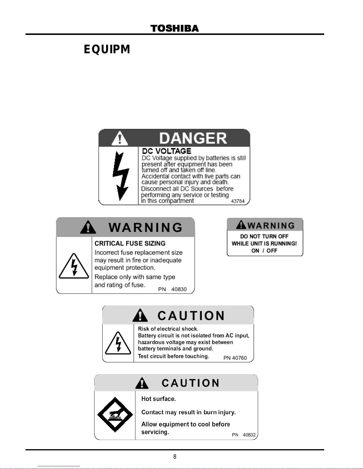
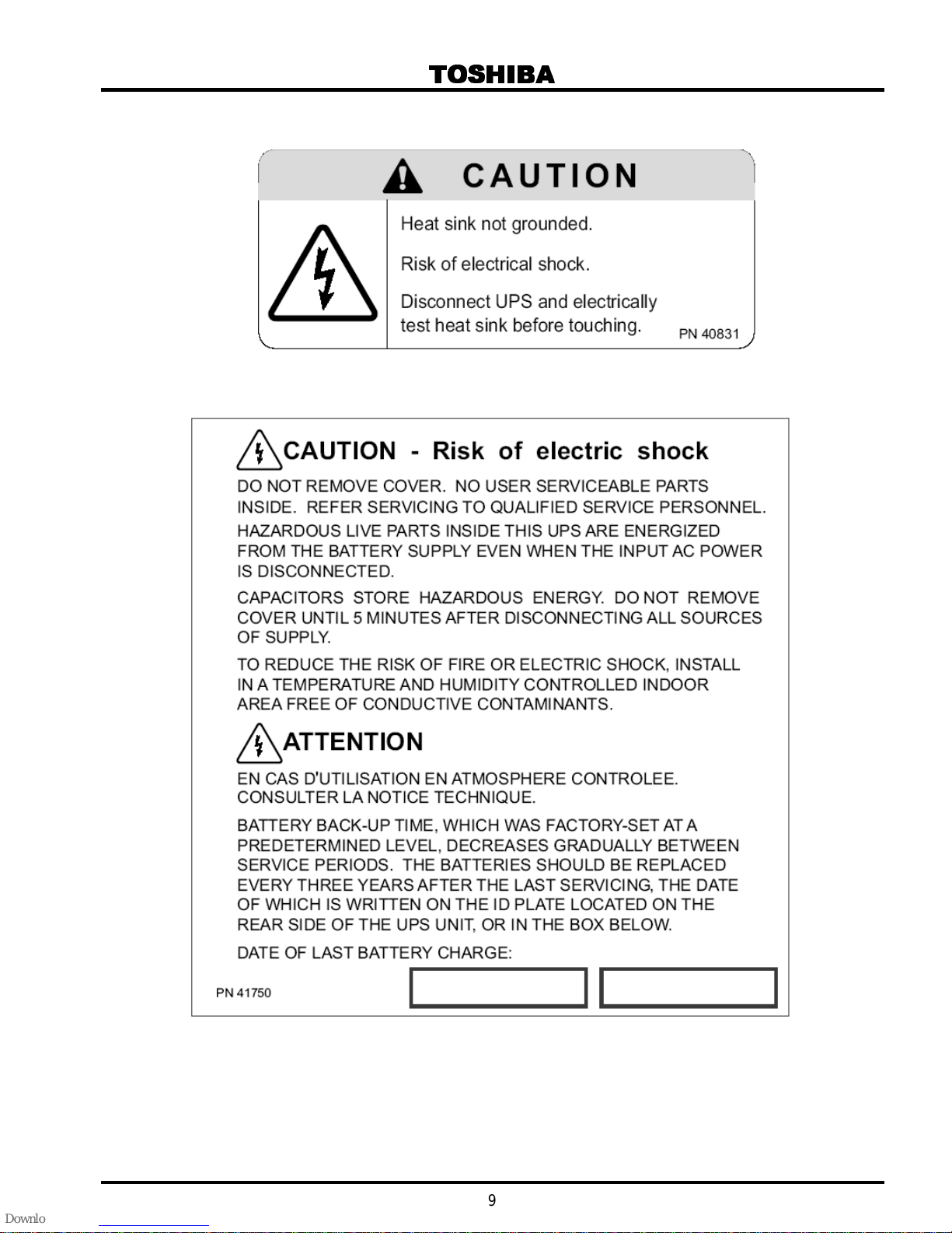
EQUIPMENT WARNING LABELS
DO NOT attempt to install, operate, maintain or di spose of this equipment until you have read and
understood all of the product warnings and user direct ions that are contai ned in this instruction manual.
Shown below are examples of warni ng labels that may be found attached to the equipment. DO NOT
remove or cover any of the labels. If the labels are damaged or if additional labels are required, contact
your Toshiba representative for additional labels.
The following ar e ex am ples of the warning labels that may be found on the equipment. The labels are ther e
to provide useful information or to indic ate an imminently hazardous situat ion that may result in serious
injury, severe property and equipment damage, or death if the instructions are not followed.
8
TOSHIBA
9
TOSHIBA
SAVE THESE INSTRUCTIONS
IMPORTANT SAFETY INSTRUCTIONS
This manual contains important instructions
that should be followed during the
installation, operation, and maintenance of the UPS and its batteries. Turn off, lockout, and tagout all
power sources befor e pr oc eeding to connect the power wiring t o the equipment or when performing
maintenance. Hardwire type UPS units are not equipped wit h an over-current protection device nor an
output disconnect for the AC output. Theref or e, a cir c ui t breaker should be provided by the user
between the UPS output and t he l oad input. This device should be rat ed as follows:
Device Type 75kVA 80kVA
Rated Output 208/120VAC 208/120VAC
Device Rating 240V, 270A 240V, 300A
The maximum ambient t em per ature in which the UPS unit should be operated is 40°C (104°F).
The nominal batter y v oltage is 288VDC.
Only a qualified Toshi ba Repr esentative who is knowledgeable in batteries and the required precautions
should only perf orm bat tery servicing. Keep unauthorized personnel away fr om batt eries. To arrange for
battery replac em ent, contact your nearest Toshi ba authorized service c enter.
Qualified Personnel ONLY
A Qualified Person i s one that has the skills and knowledge relating the construction, installation, operation
and maintenance of the elec trical equipment and has received safety training on the hazar ds i nvolved
(Refer to the latest edition of NFPA 70E for additional safety requirements).
Qualified Personnel Shall:
1) Have carefully read t he entire operation manual.
2) Be trained and authorized to safely energize, de-ener gize, ground, l ockout/tagout circuits and
equipment, and clear faults in accordance with established safety practices.
3) Be trained in the proper c ar e and use of pr otective equipment such as safety shoes, rubber gloves,
hard hats, safety glasses, face shields, fl ash clothing, etc., in acc or danc e with established safety
practices.
4) Be trained in rendering first aid.
5) Be knowledgeable of batteries and the requir ed pr ec autions.
For further info rmat io n of workpl ace saf ety visit www.osha.go v.
Refer to the Battery System M anual when scheduling batter y maintenance or battery replacem ent.
DANGER
indirect, or c onsequential damage or injury that may result from the use of this equipm ent.
Misuse of this equi pm ent could result in injury and equi pm ent damage.
In no event will Toshi ba Cor por ation be responsible or l iable for direct,
CAUTION
CAUTION
Do not open or mutilat e the bat teries. Released elect r ol yte is tox ic and
harmful to the eyes and skin.
Do not dispose of the batteries in a fire. The batteri es may
explode.
10
TOSHIBA
CAUTION
and/or flam e. An author iz ed technician must perform annual pr ev entative maintenanc e.
CAUTION
resulting in secondary faults such as odor, smoke, and fire.
CAUTION
unauthorized per sonnel away from the batteries.
CAUTION
reliability of your UPS system. Refer to service manual.
DANGER
when working with batteries:
This unit contains sealed lead acid batteries. Lac k of prev entative
maintenance could result in batteri es exploding and emitting gasses
Failure to replace a battery before it becomes exhausted may cause
the case to crack; possibl y r eleasi ng electrolyte f r om the batt er y
Only personnel knowledgeable of batteries and the r equired
precautions should perform install ation and servicing of batt eri es. K eep
Proper maintenance to the battery system of this unit m ust be done by
a qualified service technician. Thi s is essential to the safety and
A battery can present a risk of electrical shock and high short
circuit current .
The following pr ec autions should be observed
TO BE PERFORMED BY QUALIFIED PERSONNEL ONLY!
1) Verify that t he UPS is off and i s di sconnected from the power source.
2) Remove watches, rings, or other metal objects.
3) Use tools with insulated handles to prevent inadv er tent shorts.
4) Wear rubber gl ov es and boots.
5) Do not place tools or m etal parts on top of the batteries.
6) Determine if the batt ery is inadvertently grounded. If inadvertently gr ounded, remove
source of ground.
electrical shock.
removed during installation and maintenance.
7) Verify circ uit polarities prior to maki ng c onnec tions.
8) Disconnect charging source and load prior t o connecting or disconnecting t erminals.
9) VRLA batteries cont ain an explosive mixture of hydr ogen gas. Do not smoke, or create a flame
or spark in the immedi ate area of the batteries. This inc ludes stat ic electricity from the body.
10) Do not attempt to open the batteries in order to add water or sample the specific gravit y of t he
electroly te. The batteries are valve- r egulated lead acid type and such servici ng is not possible
without damagi ng the battery.
11) Use proper lifting means when moving bat teries and wear all appropriate safety clothing and
equipment.
12) Do not dispose of lead acid batteries except through channels in accordance with local, state
and federal regulations.
Contact with any part of a grounded b at tery can result in
The likelihood of such shock will be reduced if such grounds are
11
TOSHIBA
INSTRUCTIONS IMPORTANTES CONCERNANT
LA SÉCURITÉ
CONSERVER CES INSTRUCTIONS
ATTENTION
ATTENTION
Un battery puet présenter un r isque de choc électri que, de brûlure
par transfer t d’ énergie.
L’élimination des batteries est règl em entèe. Consultar les codes
locaux à cet effet
Cette notice contient des
instructions importantes
concernant la sécur té
12
1.0 Product Description
1.1 Theory of Operation
An Uninterruptible Power System (UPS) is a system t hat is installed between the commerci al
power and the load equi pment. The UPS provides steady AC output power duri ng c om m er ci al
power fluctuations and interruptions.
During normal operation the UPS receives comm ercial AC power and removes any high
voltage spik es and tr ansi ents caused by switching or faults on the main utility. The result of this
process is maxim um power conditioning and regul ation of the power applied to the load.
If the AC power supplied t o the UPS dr ops bel ow a specif ied voltage level, the batteries of the
UPS are automati c ally switc hed on and will supply power to the load. This insures that the
loads connected to t he UPS c ontinue to receive power with no inter r uption. This power is
provided for a peri od long enough to ensure that the load can be shut down in an orderly
fashion. This prevents loss of data and possible damage to the hardware or software.
When AC input power becom es available again, normal system oper ation resumes and the
UPS battery-char ge c y cl e r esumes.
1.2 Application and use
Toshiba's 4200FA Uninterruptible Power Systems (UPS) pr ov ide c ontinuous computer grade
AC power in a compact and effi ci ent high-performance unit. The UPS assures safe, reliable
operation of critical office equipment, ranging from personal c om puters to mini-computers to
local area networks (LAN). All units feature an audible alarm that sounds if the batt er y v oltage
drops below standard during use. This is an additional ai d to help in retaining the valuable
office data banks, and all units allow for computer interfacing.
TOSHIBA
1.3 Power Backup
During an electri c al power failure the batteries of the UPS unit supply DC power to the inverter
that supports the l oad equipment automatically , without interrupti on. For example, when used
to support a computer , a UPS backup assures addi tional time to complete your activity and
store data after a power f ailure occurs.
1.4 Power Conditioning
While commercial power i s present, the UPS supplies conditioned power to the load while
maintaining the batteries in a charged condi tion. The UPS protects the connect ed load against
the normal everyday pr oblems associated with heav y use of raw commerci al power, including
power sags, surges, signal interference, and spi kes. This protection keeps power-l ine problems
from reaching your load where i t can cause equipment to operate erratically, or damage
software or hardware.
13
TOSHIBA
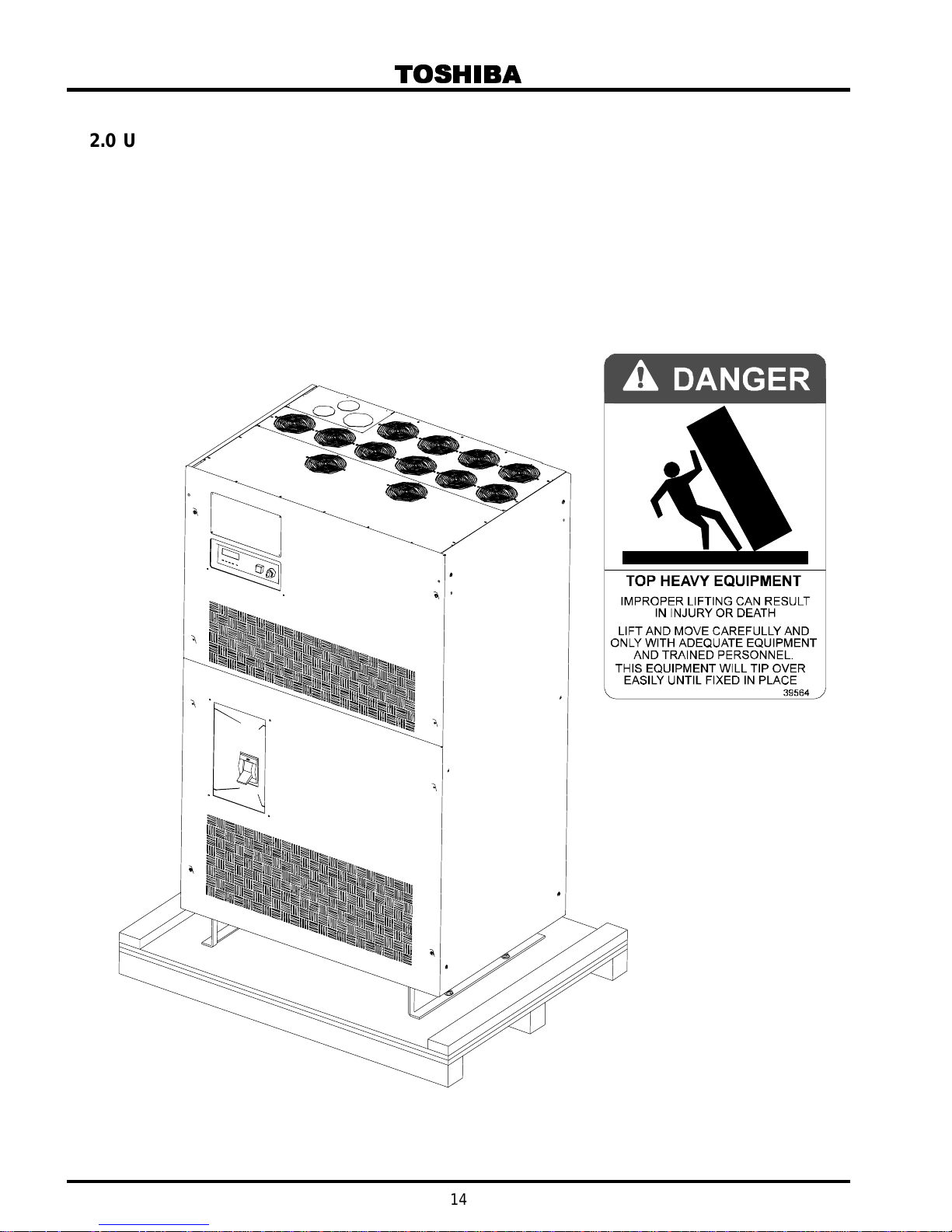
2.0 Unpacking/Inspection/Storage/Disposal
2.1 Unpacking the UPS Equipment
1) Upon receipt of t he UPS, a careful inspection for shipping damage should be made.
2) For units shipped in a c r ate, r em ov e the screws that at tach the shipping crat e panels to
each other and to the pallet. Remove the crate and foam packing materi al.
3) Unbolt the unit fr om t he shi pping pallet.
4) Lift the UPS from the pallet usi ng a forklift that has suffici ent capacity. Approach the
UPS only from the front or rear.
14
2.2 UPS Equipment Insp ection
ATTENTION
UPS Equipment Insp ection
Upon receipt of the UPS, a car eful inspection for shipping damage should be made. Use
caution when rem ov ing unit from pallet. Refer to labels or docum entation attached to
packing material.
After Uncrating
1) Check the unit for loose, brok en, bent or other damaged parts. If damage has occurred
during shipment, keep all original crating and pac king materials for ret ur n to t he
shipping agent. The equipment warranty will not apply to units that are damaged
during shipment.
2) Check to see that the rat ed c apaci ty and the model number specifi ed on the nameplate
conform to the order specif ications.
2.3 Storage of the UPS Equipment
If the UPS equipment is t o be subject to long or short-term storage, the f ol lowing guidelines
should be used.
Avoid:
1) Storage in sites subject to extreme changes in temper ature or high humidity.
2) Storage in sites subject to exposure of high lev els of dust or metal par ticles.
3) Storage on incli ned floor surfaces or in sites subject to excessive vibration.
TOSHIBA
2.4 Disposal
Before Storing:
1) Allow the UPS to be operated for 24 hours to ensure that the batteries are fully
charged.
2) Stop the unit (see Stopping the UPS in section 6.12).
3) Place the MCCB switch of t he UPS in the OFF positi on ( see section 4.1for
location).
Storing:
1) Store within t he temper ature range of –20°C to 40°C (-4°F to 104°F).
2) For best results, stor e the UPS in the original shipping c ontainer and place on
a wood or metal pallet.
3) The optimum storage temperature is 21°C (70°F). Higher am bient
temperatures cause UPS bat teries to require rec harging more frequently.
After Storing:
1) If stored in an ambient temper ature less than 20°C (68°F); rec har ge the
batteries every 9 months.
2) If stored in an ambient temper ature of 20°C to 30°C (68°F to 86°F); recharge
the batteries every 6 months.
3) If stored in an ambient temper ature of 30°C to 40°C (86°F to 104°F); r ec har ge
the batteries every 3 months.
Please contact y our state env ironmental agency for details on proper disposal of el ectrical
components and packaging in your particular ar ea.
It is illegal to dump lead-acid batteries in landfills or dispose
of imprope r ly . Pl ease hel p our E arth by contacting the
environment al pr otection agencies in your ar ea, t he battery
manufacturer , or call Toshiba toll-fr ee at ( 800) 231- 1412 for more
information about recycling batteri es.
15
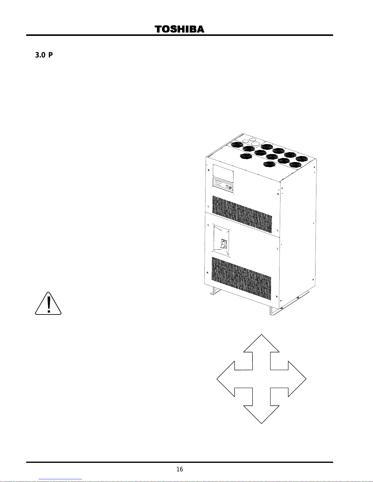
3.0 Precautions
Because of the exter nal dimensions of the 4200FA UPS and the way the outer panels are to
be removed; onl y a minimum amount of space around the unit is requir ed for v entilation and
maintenance access. Figure 3.1 shows the minimum clearanc es required for proper UPS
installation.
3.1 Installation P recautions
1) Install the UPS in a stable, level, and upright positi on that is free of vibration.
2) Install the UPS in a well ventilated location with the required allowances for v entilation
and servicing as shown in fi gur e 3.1.
3) Install the UPS where the ambient
temperature is within the correct
operating range ( see the UP S
Specifications in section 5.1). Verify that
the ventilation and air conditioni ng
system at the site is capable of
removing the heat gener ated by the
UPS unit (see Section, 5.1
Specifications, "Environment " ). Ambient
temperature r ange for operating the
UPS is 0°C – 40°C (32°F – 104°F);
25°C (77°F) is the reco mmend ed
operating temperature for maximum
battery life.
4) Do not install the UPS in a locati on that
is subject to high humi dity.
5) Do not allow the UPS to be exposed to
direct sunli ght.
6) Do not install the UPS in areas that are
subject to contamination such as high
levels of air bor ne dust, metal particles,
or flammable gasses.
7) Avoid install ation near sources of
electric al noise and always ensure that
the earth ground is intact to prevent
electrical shock and help prevent
electric al noise.
8) Do not install the UPS in an area t hat
may expose the UPS to water or that
may allow any foreign matter to get
inside.
9) This UPS generat es and radiates radiofrequency energy dur ing operation.
There is no guarantee that the UPS will
not influence some sensitive devices
that are operati ng cl ose by. If such
interfer ence is experienced, the UPS
should be installed farther away from
the affected equi pment and/or powered
from a different source than the affected
equipment.
10) The user should prov ide output over
current protection for hardwired UPS
versions. See S afety Instructions on
page 10 for the corr ect dev ic e r ating.
TOSHIBA
REAR
0” (0mm)
TOP
LEFT
0” (0mm)
22” (550 mm)
FRONT
28” (700 mm)
RIGHT
0” (0mm)
Figure 3.1
16
11) After ensuring that all power sources are turned off and isolated in accordance wit h
reset.
established loc k out/tagout procedures, connec t power source wiring of the cor r ec t
voltage to the input terminals of the UPS. Connect the output t erminals of the UPS to an
applicable load type application (ref er to NEC Arti cl e 300 – Wiri ng M ethods and Article
310 – Conductors For Gener al Wiring). Size the branch circuit conductors in accordanc e
with NEC table 310.16.
3.2 Pre-start Precautions
Before connecting the UPS to a power source; move the MCCB switch (ON/OFF ) to the OFF
position and move the oper ation RUN/STOP key switch, on the front panel ( S ee S ection 6.5
for location), to the STOP position.
3.3 Operating Precautions
1) The UPS should not be powered up until the entire Operati on Manual has been read.
2) The input power source voltage must be within +10% to -30% of the rated input voltage.
The input frequenc y m ust be within the rated input frequency r ange. Voltages and
frequencies outsi de of the permissible range m ay activate the internal prot ec tion device.
3) The UPS should not be used with a load that has a rated input greater than the r ated
UPS output.
4) Do not use the UPS to provi de power to motor s that require high starting cur r ent or a
long starting time such as vacuum cleaners or machine tools (over sizing for loc k ed rotor
current required).
5) Do not insert metal objects or combustible materi als i n the ventilation slots of t he UPS.
6) Do not place, hang, or paste any objec ts on the top or on the exterior surfaces of the
UPS.
7) The capacitors of the UPS maintain a residual charge f or a whil e aft er turning off the
UPS. The requir ed discharge time for each UPS typeform is provided via a cabinet label
and a CHARGE LED. Wait for at least the mi nim um tim e indic ated on the label and
ensure that the CHARGE LED has gone out before removing the front panel of the UPS
once the UPS power has been turned off .
8) Do not attempt to disassembl e, modify, or repair the UPS. Call y our Toshiba sal es
representative for repair information.
9) Turn the power on only aft er att ac hing ALL the covers and DO NOT remove any covers
of the UPS when the power is on.
10) If the UPS should emit smoke or an unusual odor or sound, turn the power off
immediately.
11) The heat sink and other components may become extremely hot to the touch. Allow the
unit to cool before c oming into contact with these items.
12) Warning si gns should be placed on or near the load to let people k now that the load is
being powered by the UPS.
13) Additional warnings and notific ations shall be posted at the equipm ent installation
location as deem ed r equir ed by Qualified Pe r s on ne l.
TOSHIBA
CAUTION
UPS will conti nue to prov ide power to the load. The unit must be in Bypass mode and then
the breaker tur ned to the OFF position for the UPS to shut down power to the l oad.
CAUTION
When the UPS is in the Inverter m ode, t ur ning the breaker to the OFF
position will cause the unit to go into the battery back up mode. The
Do not EPO (Emergency Power OFF ) the UP S and then r eset the
breaker until the UPS has been fully discharged. T he UPS could be
damaged if the unit is not f ull y powered do wn before the breaker is
17
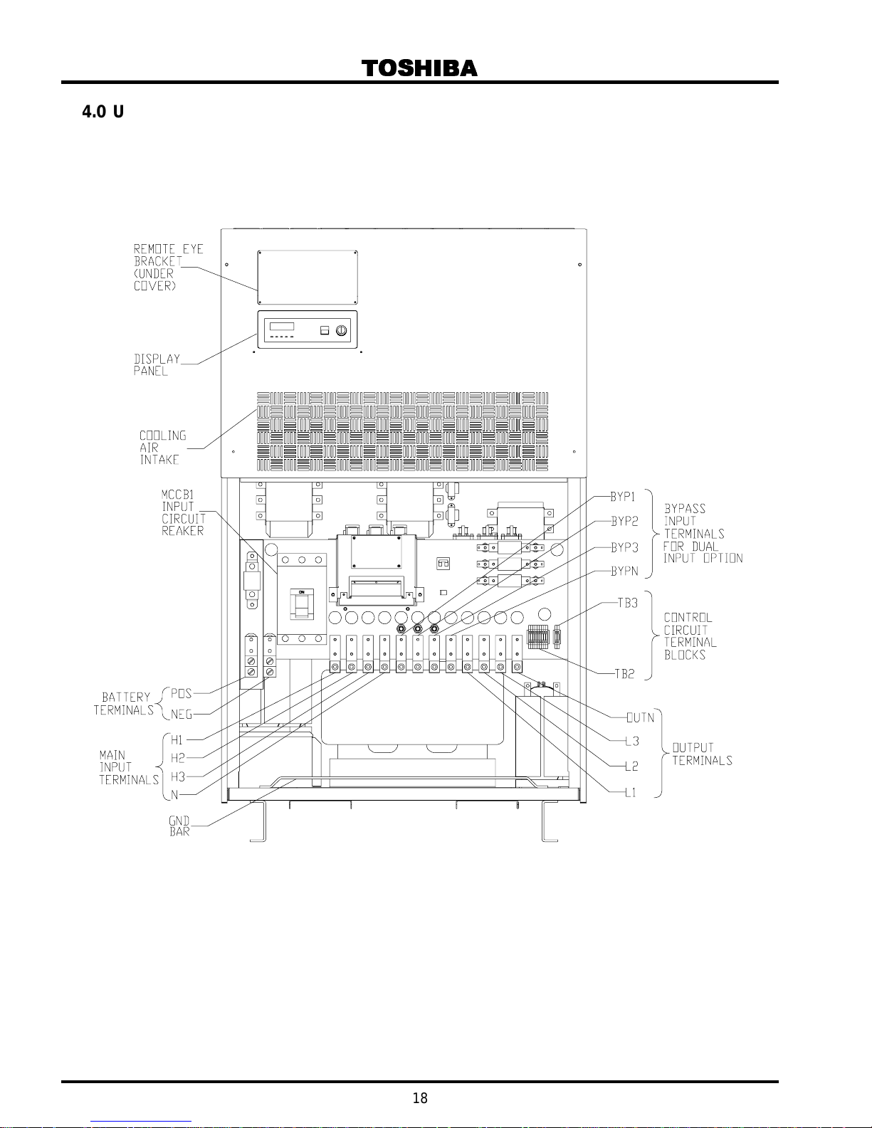
4.0 UPS Connections
4.1 UPS Power and Control Connection s
The following illustration shows the wiring c onnec tions to the input and output termi nation
points and the Control Cir c uit Terminal Blocks for the 4200FA 75/80 kVA UPS.
TOSHIBA
18
 Loading...