

Toshiba T3300SL Maintenance Manual

Chapter 1
Hardware Overview
1-1

This page intentionally left blank
1-2

Contents
1.1 T3300SL Features .............................................................................................................1-5
1.2 The System Unit Block Diagram ....................................................................................... 1-8
1.3 3.5-inch Floppy Disk Drive............................................................................................. 1-11
1.4 2.5-inch Hard Disk Drive ................................................................................................ 1-12
1.5 Keyboard ........................................................................................................................ 1-13
1.6 Sidelit Liquid Crystal Display ......................................................................................... 1-14
1.6.1 LCD Module........................................................................................................ 1-14
1.6.2 FL Inverter Board................................................................................................ 1-15
1.7 Power Supply Board........................................................................................................ 1-16
Tables
Table 1-1 3.5-inch FDD specifications ................................................................................... 1-11
Table 1-2 2.5-inch HDD specifications ..................................................................................1-12
Table 1-3 Sidelit LCD specifications ..................................................................................... 1-14
Table 1-4 FL inverter board specifications............................................................................. 1-15
Table 1-5 Power supply board output rating........................................................................... 1-16
Figures
Figure 1-1 T3300SL personal computer ..................................................................................... 1-7
Figure 1-2 System unit configuration ........................................................................................1-7
Figure 1-3 Block diagram .......................................................................................................... 1-8
Figure 1-4 3.5-inch FDD.......................................................................................................... 1-11
Figure 1-5 2.5-inch HDD ......................................................................................................... 1-12
Figure 1-6 Keyboard................................................................................................................ 1-13
Figure 1-7 Sidelit LCD ............................................................................................................ 1-14
Figure 1-8 Power supply board ................................................................................................ 1-16
1-3

This page intentionally left blank
1-4

1.1 T3300SL Features
The Toshiba T3300SL is one of the lightest and most advanced portable computers available.
Utilizing advanced technology and high speed components, the T3300SL offers excellent display
legibility, battery operation, and IBM PC/AT compatibility.
The T3300SL system unit consists of the following features:
❑ An 80386SL-25 32-bit microprocessor, operating at 25MHz, 12.5MHz or 6.25MHz.
❑ Standard Random Access Memory (RAM) capacity is 2MB. Optional 2, 4, 6 or 16MB
expansion cards can be installed, thus expanding RAM memory to a maximum of 18MB.
❑ An optional 80387SX-25 Numeric Data Processor (NDP) can be installed in the built-in
socket located on the bottom of the T3300SL.
❑ A high resolution, fully adjustable Liquid Crystal Display (LCD) is composed of 640
horizontal and 480 vertical pixels and displays 25 lines of standard text 80 characters wide.
The LCD displays 32 levels of gray (at a resolution of 320 x 200) and supports the High
Resolution Graphics Subsystem (HRGS), including VGA functions.
❑ The 3.5-inch internal Floppy Disk Drive (FDD) supports both 1.44MB Double-sided, High-
density, Double-track (2HD) and 720KB Double-sided, Double-density, Double-track
(2DD) floppy disk.
❑ The integrated 2.5-inch 80 or 120MB Hard Disk Drive (HDD) provides nonvolatile storage
for software and data.
❑ An 82/84-key keyboard has full-sized keys, a numeric keypad overlay, cursor, and page
control. The keyboard supports software that uses the industry standard 101/102-key
keyboard.
❑ The universal auto-sensing AC adapter supplies power to operate the T3300SL and recharge
its batteries. It can operate from a range of 100 to 240 volts. Optional power cords support
various countries’ AC outlet configurations.
❑ A PS/2 mouse connector is located on the right side of the T3300SL.
❑ A Personal Computer Memory Card International Association (PCMCIA) standard release
2.0 slot allows you to install a Toshiba card modem or an industry standard card in the
T3300SL.
❑ Serial devices can be connected to the T3300SL’s standard 9-pin RS-232-C serial port.
1-5

❑ One selectable Centronics-compatible parallel port allows the T3300SL to interface with
optional parallel devices.
❑ The Toshiba AutoResume feature stores the T3300SL’s data in backup RAM when the
power is turned off.
❑ The Real Time Clock (RTC) IC chip and battery continuously update the date and time and
keep the system configuration even when the T3300SL power is off.
1-6
The T3300SL Personal Computer is shown in Figure 1-1. Its system configuration is shown in
Figure 1-2.
Figure 1-1 T3300SL personal computer
HDD
Sub Battery
PJ21
PJ5
PJ10
Keyboard LCD
PJ15
Display
Switch
PJ12
AC Adapter
Power Supply
Board
PJ9
PJ2
PJ19
PJ4
PJ13
PJ11
LED
Battery Pack
RTC Battery
PS/2 Mouse
FDD
Figure 1-2 System unit configuration
1-7

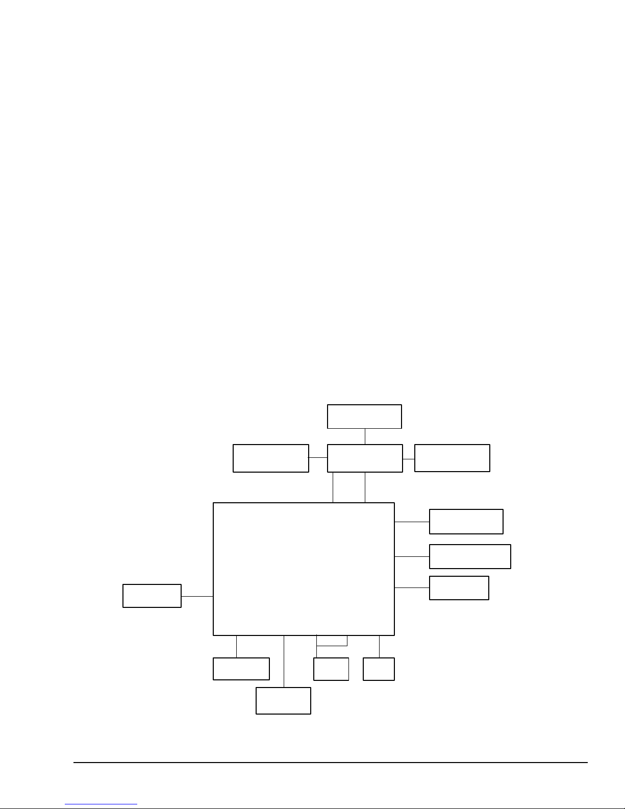
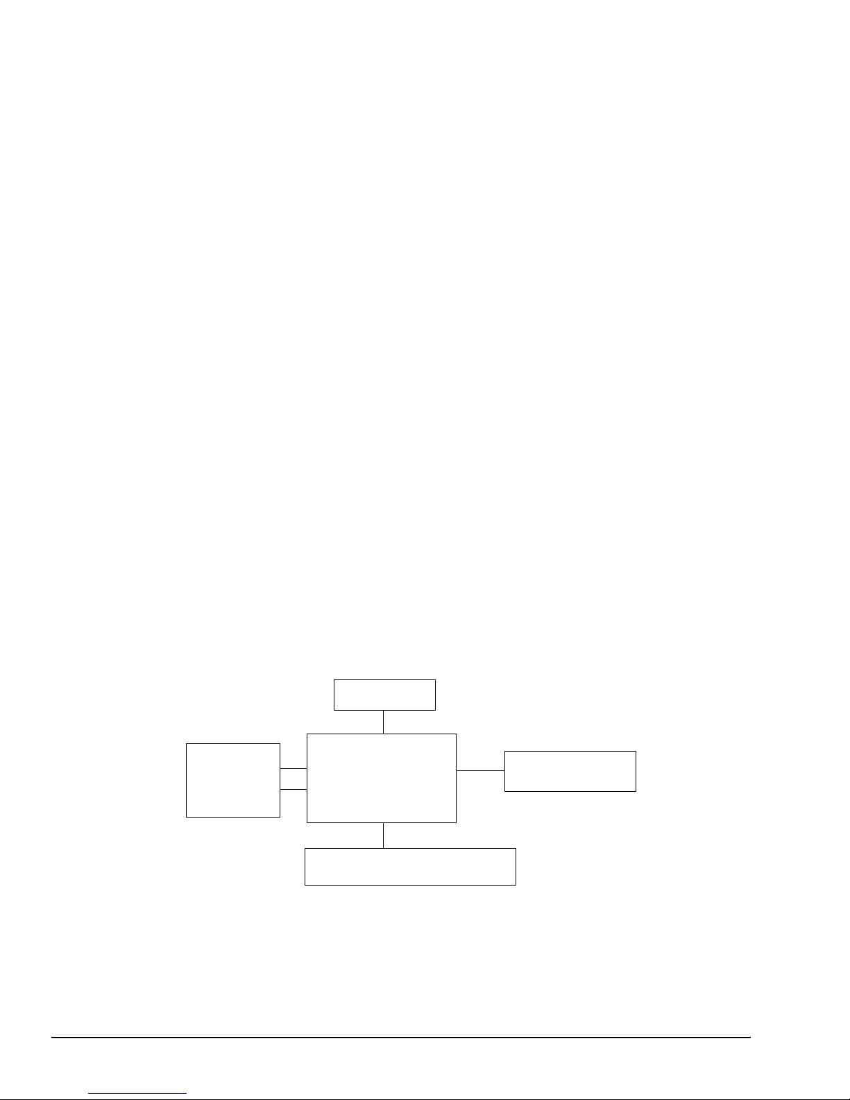
1.2 The System Unit Block Diagram
Figure 1-3 is a block diagram of T3300SL system unit.
1-8
Figure 1-3 Block diagram

The T3300SL system board diagrammed in Figure 1-3 is composed of the following major components:
❑ 80386SL-25 CPU
❑ Socket for an optional 80387SX-25 Numeric Data Processor (NDP)
❑ 82360SL ISA peripheral I/O chip contains the following components:
Two Direct Memory Access Controllers (DMACs): 82C37A
Two Programmable Interrupt Controllers (PICs): 82C59A
Two Programmable Interval Timers (PITs): 82C54
(T3300SL uses one PIT)
Two Serial Input/Ouput Controllers (SIOs): 16C450
(T3300SL uses one SIO)
One Real Time Clock (RTC): 146818AF
❑ Super Integration (SI), T9920, which stores the following components:
One Floppy Disk Controller (FDC): TC8565
One Variable Frequency Oscillator (VFO): TC8568
❑ Keyboard Controller (KBC): M37452M4
❑ Power Supply Controller (PSC): U47C660
❑ Memory:
Standard RAM: 2MB
BIOS ROM: 128KB (96KB are used)
BIOS ROM contains the Initial Reliability Test (IRT), the system’s
Basic Input/Output System (BIOS), and the video BIOS.
Video RAM: 256KB
Cache memory: 64KB
Optional memory cards can expand the memory to a maximum of 18MB.
❑ IC card controller gate array: GA-ICCNT (144-pin)
❑ Refresh controller gate array: GA-REFCNT (44-pin)
❑ VGA display controller (WD90C21): PVGA1F (132-pin)
1-9

❑ The following Oscillators (OSCs):
50.0MHz OSC (X1) and 16.0MHz OSC (X2) are used for the CPU.
14.7456MHz OSC (X3) is used for the COM.
14.31818MHz OSC (X4) is used for the KBC.
24MHz OSC (X5) is used for the FDC and VFO.
32.768KHz OSC (X6) is used for the RTC.
44.9MHz OSC (X7), 28.322MHz OSC (X8), and 25.175MHz OSC (X9) are used for the
video.
See Appendix A for the locations of the oscillators on the system board.
1-10
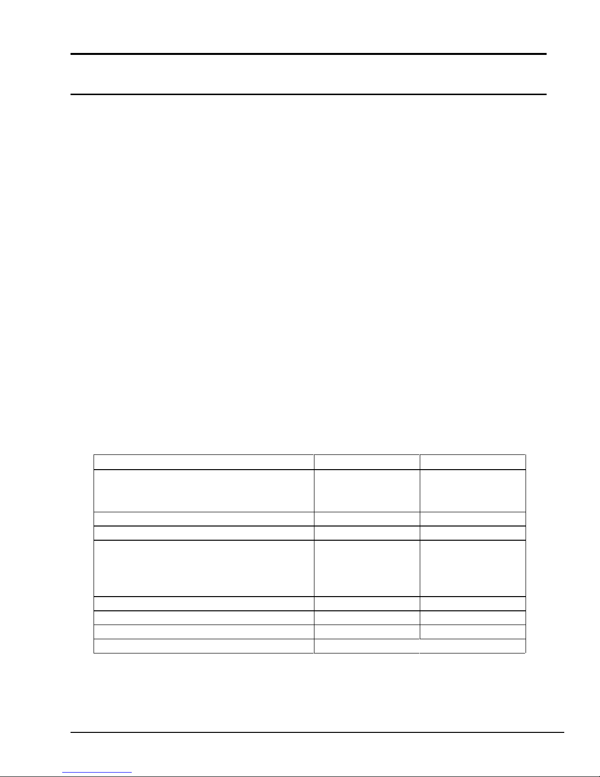
1.3 3.5-inch Floppy Disk Drive
Recording method Modified Frequency M odulation (M FM)
The T3300SL 3.5-inch Floppy Disk Drive (FDD) is a thin, high performance, reliable drive that
supports 720KB (formatted ) 2DD and 1.44MB (formatted) 3.5-inch floppy diskettes.
The T3300SL FDD is shown in Figure 1-4. Specifications for the FDD are described in Table 1-1.
Figure 1-4 3.5-inch FDD
Table 1-1 3.5-inch FDD specifications
Item 2-Mbyte mode 1-Mbyte mode
Storage capacity (Kbyte)
Unformatted
Formatted
Number of heads 2 2
Number of cylinders 80 80
Access time (ms)
Track to track
Average
Head settling time
Recording track density (tpi) 135 135
Data transfer rate (Kbps) 500 250
Rotation speed (rpm) 300 300
2,000
1,440
3
94
15
1,000
720
3
94
15
1-11
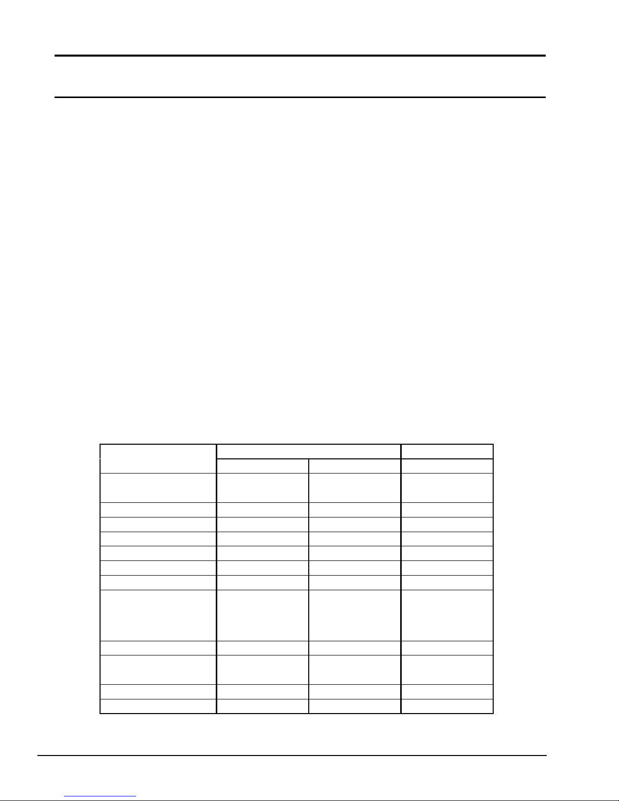
1.4 2.5-inch Hard Disk Drive
Recording metho
-7 RLL
-7 RLL
-7 RLL
The 80MB or 120MB (formatted) Hard Disk Drive (HDD) is a random access, nonvolatile storage
device. It is equipped with a non-removal 2.5-inch magnetic disk and mini-Winchester type
magnetic heads.
The T3300SL HDD is shown in Figure 1-5. Specifications for the HDD are described in Table 1-2.
Figure 1-5 2.5-inch HDD
Table 1-2 2.5-inch HDD specifications
It em
Sto rage capacity
Formatted (MB)
Num ber of disks 2 2 2
Data heads 4 4 4
Data surfaces 4 4 4
Tr acks per surface 7 91(+ 2) 97 7 934
Sectors per track 35(+1) 43 (+3) 55(+1)
Bytes per sector 512 512 512
Access time (ms)
Track to track
Average
Maximum
Rotation speed (r pm) 3,118 3,200 3,200
Data transfer rate (MB/S)
To/from media
Interleave 1:1 1:1 1:1
d 1
JDE2085M MK2024FC MK 2124FC
85 .68 86.0 130.1
9
2 5
4 7
5.0M 5.0M 6.5M
80MB 120 MB
5
19
40
1
5
1 7
3 6
1
* Run Length Limited
1-12

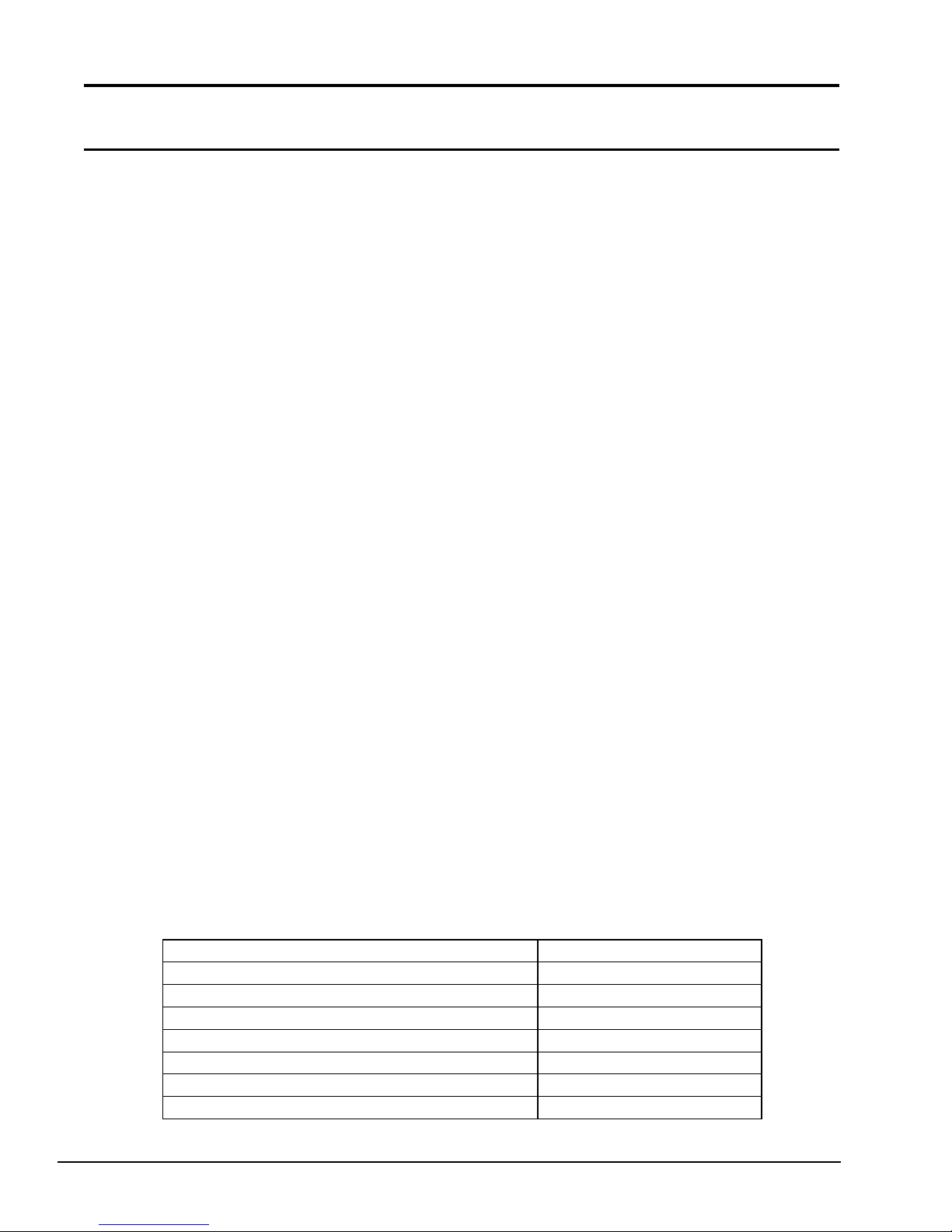
1.5 Keyboard
The 82-key (USA) or 84-key (European) keyboard is mounted on the system unit. The keyboard is
connected to the keyboard controller on the system board through a 19-pin flat cable. The keyboard is shown in Figure 1-6.
See Appendix E for optional keyboard configurations.
Figure 1-6 Keyboard
1-13
1.6 Sidelit Liquid Crystal Display
FL frequency (KHz) 35 to 43
The sidelit Liquid Crystal Display (LCD) contains a LCD module, a Fluorescent Lamp (FL), and an
FL inverter board.
1.6.1 LCD Module
The T3300SL sidelit LCD supports 640x480 pixels with the High Resolution Graphics Subsystem
(HRGS) and a 32 levels of gray (at a resolution of 320 x 200). The HRGS includes the functions of
the Video Graphics Array (VGA).
The LCD receives vertical and horizontal synchronizing signals, 8-bit data signals (4-bit upper data
signal, 4-bit lower data signal), and shift clock for data transmission from the PVGA1F Video
Controller. All signals are CMOS-level compatible.
The sidelit LCD is shown in Figure 1-7. Specifications for the LCD are described in Table 1-3.
Figure 1-7 Sidelit LCD
Table 1-3 Sidelit LCD specifications
Item Specifications
Numbe r of dots (dots) 640 x 480
Dot dimension (mm) 0.24(W) x 0.24 (H)
Dot pitch (mm) 0.27 (W) x 0.27 (H)
Display are a (mm) 196.0 (W) x 147.06 (H)
Contrast 15:1 (typ.)
FL c urrent (mA) 4.0 to 6.0
1-14
1.6.2 FL Inverter Board
Bounds of current (mA) 2.5 - 5.5
The FL inverter board supplies the high frequency current needed to illuminate the LCD’s fluorescent lamp.
The specifications for the FL inverter board are described in Table 1-4.
Table 1-4 FL inverter board specifications
Ite m Specifications
Input Voltage (VDC) 11- 26
Power (W) 2.8 (Max.)
Output
Voltage
Current
Frequency
(VAC) 1100 (r.m.s.)
(mA) 5.5 (r.m.s.)
(KHz) 44
1-15

1.7 Power Supply Board
Side lit LCD (DSPV) +12 to +18.9 200
The power supply board supplies five voltages to the system board. The power supply board has
one microprocessor which operates at 500KHz.
The power supply board contains the following functions:
❑ Determines if the AC adapter or battery is connected to the computer.
❑ Detects DC output and circuit malfunctions.
❑ Controls the LED indicator panel and speaker.
❑ Turns the battery charging system on and off and detects a fully charged battery.
❑ Determines if the power can be turned on and off.
❑ Provides more accurate detection of a low battery.
❑ Calculates the remaining battery capacity.
The power supply board is shown in Figure 1-8 and the output ratings are specified in Table 1-5.
Figure 1-8 Power supply board
Table 1-5 Power supply board output rating
DC
Item
System logic, FDD, HDC, HDD (VCC) +5 ±5 2,600
Backup RAM (R AMV) +4.7 ±5 950
RS-232-C (VDD) +12 ±5 75
RS-232-C (VEE) -9 ±15 60
voltage
(V)
Regulation
Tolerance
(%)
Maximum
Current
(mA)
1-16

Chapter 2
Troubleshooting Procedures
2-1

This page intentionally left blank
2-2

Contents
2.1 T3300SL Troubleshooting ...................................................................................................2-5
2.2 Troubleshooting Flowchart ..................................................................................................2-6
2.3 Power Supply Board Troubleshooting Procedures ...............................................................2-8
Procedure 1 AC Adapter Check ...................................................................................2-8
Procedure 2 Battery Indicator Function Check ............................................................ 2-9
Procedure 3 Power Supply Board Connection Check................................................. 2-10
2.4 System Board Troubleshooting Procedures ........................................................................ 2-12
Procedure 1 Message Check ...................................................................................... 2-12
Procedure 2 Printer Port LED Check ......................................................................... 2-15
Procedure 3 Diagnostic Test Program Execution Check ............................................ 2-19
2.5 Floppy Disk Drive Troubleshooting Procedures ................................................................. 2-20
Procedure 1 FDD Head Cleaning Check .................................................................... 2-20
Procedure 2 Internal and External FDD Check .......................................................... 2-20
Procedure 3 Diagnostic Test Program Execution Check ............................................ 2-21
Procedure 4 Connector Check and Replacement Check............................................. 2-22
2.6 Hard Disk Drive Troubleshooting Procedures.................................................................... 2-23
Procedure 1 Partition Check ...................................................................................... 2-23
Procedure 2 Message Check ...................................................................................... 2-24
Procedure 3 Format Check ........................................................................................2-25
Procedure 4 Diagnostic Test Program Execution Check ............................................ 2-26
2.7 Keyboard Troubleshooting Procedures ..............................................................................2-27
Procedure 1 Diagnostic Test Program Execution Check ............................................ 2-27
Procedure 2 Connector and Replacement Check ........................................................ 2-27
2.8 Display Troubleshooting Procedures .................................................................................2-28
Procedure 1 Brightness and Contrast Volume Check................................................. 2-28
Procedure 2 External CRT Check .............................................................................. 2-28
Procedure 3 Diagnostic Test Program Execution Check ............................................ 2-28
Procedure 4 Connector Check .................................................................................... 2-29
Procedure 5 Replacement Check ...............................................................................2-29
Tables
Table 2-1 Power supply error statuses ...................................................................................... 2-9
Table 2-2 Printer port LED error codes .................................................................................. 2-17
Table 2-3 Floppy disk drive error codes and statuses .............................................................2-21
Table 2-4 Hard disk drive error codes and statuses ................................................................. 2-26
Figures
Figure 2-1 Troubleshooting flowchart .......................................................................................2-6
Figure 2-2 Printer port LED..................................................................................................... 2-15
Figure 2-3 Reading the printer port LED .................................................................................2-15
2-3

This page intentionally left blank
2-4

2.1 T3300SL Troubleshooting
This chapter describes how to determine if a Field Replaceable Unit (FRU) in the T3300SL is
causing the computer to malfunction. The FRUs covered are:
❑ Power supply board
❑ System board
❑ Floppy Disk Drive
❑ Hard Disk Drive
❑ Keyboard
❑ Display
The following tools are necessary for implementing the T3300SL troubleshooting procedures.
❑ T3300SL Diagnostics Disk
❑ Phillips head screwdriver (2mm)
❑ Toshiba MS-DOS system disk
❑ 2DD or 2HD formatted work disk for the floppy disk drive testing
❑ Cleaning disk kit for the floppy disk drive troubleshooting
❑ Printer port LED
❑ RS-232-C wraparound connector
❑ Printer wraparound connector
❑ Multimeter
❑ External 5.25-inch floppy disk drive
❑ External CRT
2-5
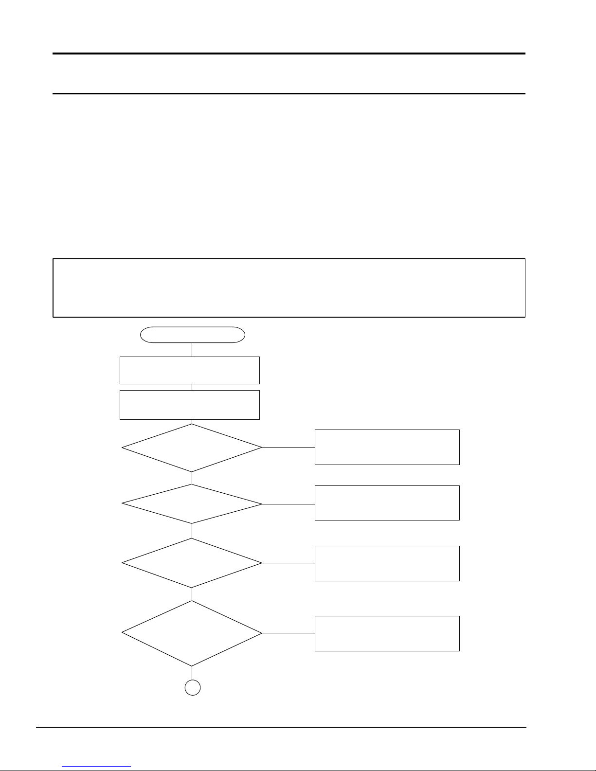
2.2 Troubleshooting Flowchart
Use the flowchart in Figure 2-1 as a guide to determine which FRU troubleshooting procedures to
execute. Before performing the flowchart steps, verify the following:
❑ Verify with the customer that Toshiba MS-DOS is loaded on the computer. Other
non-Toshiba operating systems will cause the computer to malfunction.
❑ Make sure all optional equipment is disconnected from the computer.
❑ Make sure the floppy disk drive is empty.
NOTE: If you forget the password and cannot start up the computer, connect the printer port
wraparound board (F31PRT), then turn the POWER switch on. The computer will override
the password function by erasing the current password.
START
Insert the Toshiba MS-DOS
diskette into the FDD.
Turn the Power Switch ON
and wait 5 Seconds.
Does the
POWER INDICATOR
illuminate?
YES
Is an
Error Message
displayed?
NO
Is the
MEMORY TEST XXXXKB
message displayed
?
YES
Does the
MEMORY TEST XXXKB
message proceed from
0KB to 640KB?
NO
YES
NO
NO
Perform Power Supply Board
Troubleshooting Procedures in
Section 2.3.
Perform System Board
Troubleshooting Procedures in
Section 2.4.
Perform Display Troubleshooting
Procedures in Section 2.8.
Perform System Board
Troubleshooting Procedures in
Section 2.4.
1
Figure 2-1 Troubleshooting flowchart
2-6
YES
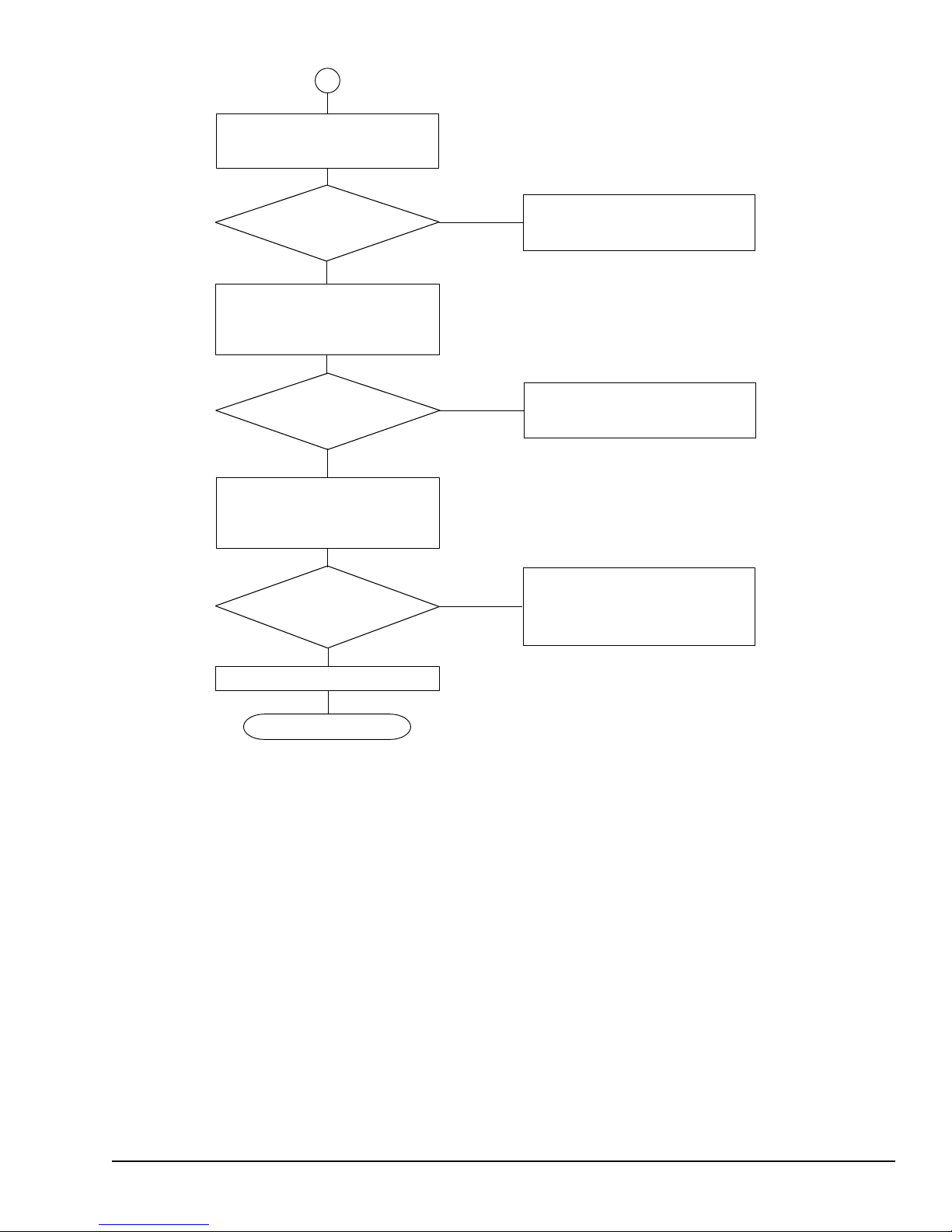
1
If the Password = prompt is
displayed, type in the user password
and press Enter.
Is Toshiba
MS-DOS being
loaded?
YES
Insert the ASP Diagnostics
diskette into the FDD, type
A:TESTCE33, and press ENTER.
Do typed
characters appear
correctly?
YES
Connect wraparound connectors.
Execute the Running Test
several times.
Is an error
detected by the
Running Test
?
NO
System is normal.
NO
NO
YES
Perform Floppy Disk Drive
Troubleshooting Procedures in
Section 2.5.
Perform Keyboard
Troubleshooting Procedures in
Section 2.7.
After confirming which test has
detected an error, perform the
appropriate troubleshooting procedures.
END
Figure 2-1 Troubleshooting flowchart (continued)
If the Diagnostic Program does not detect any errors, the problem may be an intermittent one.
Execute the Running Test program several times to isolate the problem.
After confirming which diagnostic test detected an error by checking the Log Utilities function,
perform the appropriate troubleshooting procedures as follows:
1. If an error is detected on the system test, memory test, display test, ASYNC test, printer
test, or real timer test, perform the system board troubleshooting procedures in Section 2.4.
2. If an error is detected on the keyboard test, perform the keyboard troubleshooting proce-
dures in Section 2.7.
3. If an error is detected on the floppy disk test, perform the floppy disk drive troubleshooting
procedures in Section 2.5.
4. If an error is detected on the hard disk test, perform the hard disk drive troubleshooting
procedures in Section 2.6.
2-7

2.3 Power Supply Board Troubleshooting
Procedures
The T3300SL’s power supply board controls many functions and components in the T3300SL. To
determine if the power supply board is functioning properly, start with Procedure 1 and continue
with the other procedures as instructed.
Procedure 1: AC Adapter Check
Procedure 2: Battery Indicator Function Check
Procedure 3: Power Supply Board Connection Check
Procedure 1 AC Adapter Check
The T3300SL’s AC adapter converts AC power to DC power and contains a charging circuit which
charges T3300SL’s batteries. The adapter connects to the DC IN 18V connector on the back of the
computer. When the AC adapter is connected and the T3300SL and the power is turned off, the AC
adapter charges the batteries.
The indicator panel displays the charge status of the battery pack and whether or not the AC
adapter is connected and supplying power. The indicator labeled Battery glows amber when the
AC adapter is charging the battery pack.
If the Battery indicator does not light, the AC adapter is not supplying power to the T3300SL or
the computer is turned off.
When the Battery indicator is red, the AC adapter is connected and supplying power to the T3300SL.
If the indicator is flashing red, the AC adapter’s voltage supply is abnormal or the power supply is
not functioning properly.
If any of the above indicator conditions are abnormal, make sure the LED indicator lights are not
burned out before performing the following checks.
Check 1 Make sure the AC adapter’s cable is firmly plugged into the DC IN 18V connector on
the back of the computer.
Check 2 If the Battery indicator is flashing red, its voltage output is abnormal. Connect a new
AC adapter and turn the T3300SL on again to verify the indicator condition.
Check 3 The battery pack may be malfunctioning. Replace the battery pack with a new one
and turn the computer on again. If the problem still exists, perform Procedure 2.
2-8
Procedure 2 Battery Indicator Function Check
Fh Under c urrent of charging current
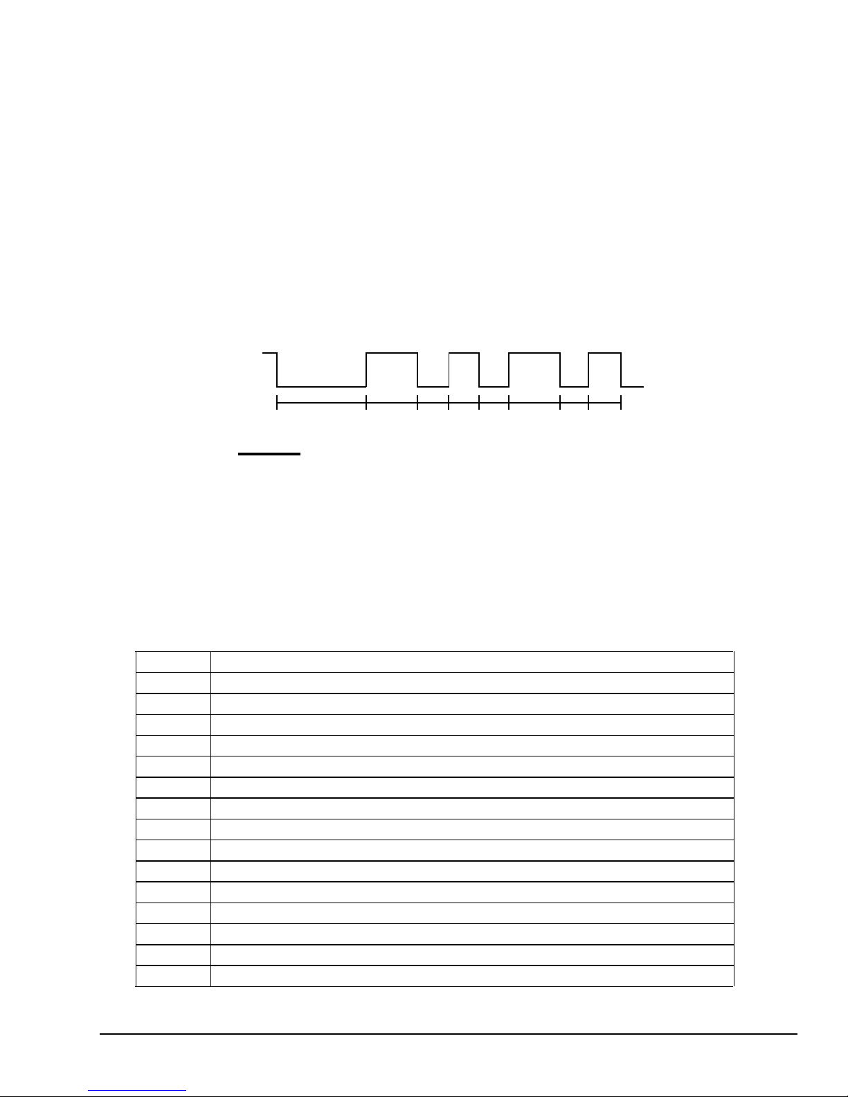
When a power supply problem occurs, the Battery indicator shows the 4-bit status by blinking at
various speeds corresponding to the type of problem.
The battery indicator lights for two seconds at first, and then blinks on for one second (indicating a
binary 1) or a half second (indicating a binary 0) at half-second intervals from bit 0 to bit 3 sequentially.
For example, the following timing chart shows the error status 5h (0101). Read the timing chart
from right to left to determine the correct hexadecimal value.
Bit 0 Bit 1 Bit 2 Bit 3
1 0 1 0
ON
Battery
OFF
2s 1s 0.5s 1s 0.5s
0.5s 0.5s 0.5s
➝
Time
The power supply error statuses and their meanings are described in Table 2-1.
When the Battery indicator blinks at random, the AC adapter or charging circuit may be damaged.
In this case, replace the AC adapter with a new one.
Table 2-1 Power supply error statuses
Status Meaning
1h Over voltage of AC adapter output voltage (more than +18V±5%)
2h Abnormal temperature in the s ystem (les s than -20°C or more than 70°C)
3h Abnormal charging (The system cannot stop charging.)
4h Over current of charging current
5h Abnormal charging voltage
6h Abnormal battery voltage
7h Abnormal VCC (+5) voltage
8h Abnormal RAMV (+5V for DRAM) voltage
9h VEE (-9V) is shorted
Ah VDD (+12V) is shorted
Bh DSPV (+ 12V to +18V for FL) is shorted
Ch Desk Station IV was turned off before the T3300SL
Dh Battery terminal is shorted
Eh Under voltage of AC adapter output voltage (less than +18V±5%)
2-9
After investigating the Battery indicator, start with Check 1 below.
Check 1 If the Battery indicator displays error status 1h, 4h, 5h, Eh, or Fh, replace the AC
adapter with a new one. If the same problem still appears, perform Procedure 3.
Check 2 If the Battery indicator displays error status 6h or Dh, replace the battery pack with a
new one. If the same problem still appears, perform Procedure 3.
Check 3 If the Battery indicator displays error status Ch, remove the T3300SL from the Desk
Station IV. Turn the T3300SL on. It should operate normally.
Check 4 If the Battery indicator displays error status 2h, place the T3300SL in an environ-
ment between -20°C and 70°C until the T3300SL is at the ambient temperature.
Repeat the steps which caused the T3300SL to operate abnormally. If the same
problem still appears, perform Procedure 3.
Check 5 If the Battery indicator displays error status 3h, 7h, 8h, 9h, Ah, or Bh, perform
Procedure 3.
Procedure 3 Power Supply Board Connection Check
The power supply board is connected to other components by various cables. These cable connectors can become disconnected from the power supply board, thus causing the T3300SL to malfunction. To check these connections, it is necessary to disassemble the T3300SL. Refer to Chapter 4,
Replacement Procedures, for more information about how to disassemble the T3300SL. Then
perform Check 1.
Check 1 The following cable connections connect the power supply board to other components.
Make sure these connections are secure and that none of the cable are pinched or
damaged.
Sub battery
PJ4
Battery PJ2 PJ5 System board
terminal PJ3
PJ1
AC adapter socket board
If any of these connections are loose, firmly secure them. Replace any broken or
damaged cables. Execute the procedures that were causing the T3300SL to malfunction. If the computer still does not function properly, perform Check 2.
2-10

Check 2 The Battery indicator status lets you know when a unit should be replaced. Refer to
3 2h, 3h, 7h, 8h, 9h, Ah, Bh Power supply board
the following table.
Condition Battery Indicator Replacement Unit
1 1h, 4h, 5h, Eh, Fh AC adapter
2 6h, Dh Battery pack
If condition 1 or 2 remains after replacement of the indicated unit, then replace the
power supply board.
If condition 3 remains after replacing the power supply board, then replace the system
board.
2-11

2.4 System Board Troubleshooting
Procedures
To determine if the system board is defective or not functioning properly, perform the following
procedures beginning with Procedure 1 and continuing with the other procedures as instructed.
Procedure 1: Message Check
Procedure 2: Printer Port LED Check
Procedure 3: Diagnostic Test Program Execution Check
Procedure 1 Message Check
When the power is turned on, the system performs the Initial Reliability Test (IRT) installed in the
BIOS ROM. The IRT tests each IC on the system board and initializes it.
If an error message is displayed, perform Check 1. If not, go to Procedure 2. If MS-DOS is properly loaded, go to Procedure 3.
Check 1 If the following error message is displayed on the screen for one second, the external
FDD is not connected, even though the external FDD/PRT option in the SETUP program is set to FDD A. Set the external FDD/PRT option to FDD B or PRT, or connect
the external FDD and restart the system. If any other error message appears, perform
Check 2.
*** FDD A is not installed ***
Check 2 If one of the following error messages is displayed on the screen, press any key as the
message instructs. These errors occur when the system configuration preserved in the
RTC memory (CMOS-type memory) is not the same as the actual one or the data is
lost.
If you press any key as the message instructs, the system configuration in the RTC
memory configuration is set to the default setting. If error message (b) appears often
when the power is turned on, replace the RTC battery. If any other error message is
displayed, perform Check 3.
(a) *** Error in CMOS. Bad HDD type ***
Check system. Then press any key ......
(b) *** Error in CMOS. Bad battery ***
Check system. Then press any key ......
2-12

(c) *** Error in CMOS. Bad check sum ***
Check system. Then press any key ......
(d) *** Error in CMOS. Bad memory configuration ***
Check system. Then press any key ......
(e) *** Error in CMOS. Bad time function ***
Check system. Then press any key ......
Check 3 If one of the following error messages is displayed on the screen, press any key as the
message instructs.
The error message (a) appears when data stored in RAM under the resume function is
lost because the battery has discharged.
The error message (b) appears when an error is detected during the read test of the
hard RAM or the data in the hard RAM is lost because the battery has discharged.
If any other message appears, perform Check 4.
(a) WARNING: RESUME FAILURE.
PRESS ANY KEY TO CONTINUE.
(b) WARNING: DATA IN HARD RAM WAS LOST.
YOU MUST FORMAT HARD RAM BEFORE USE.
PRESS ANY KEY TO CONTINUE.
2-13

Check 4 The IRT tests the system board. When the IRT detects an error, the system stops or
the error message appears. Refer to the messages in Table 2-2 to determine which test
item failed.
If one of the following (a) through (s) error messages is displayed, replace the system
board.
If error message (t) is displayed, go to the Keyboard Troubleshooting Procedures in
Section 2.7.
If the (u) or (v) error message is displayed, go to the HDD Troubleshooting Procedures in Section 2.6.
If error message (w) is displayed, go to the FDD Troubleshooting Procedures in
Section 2.5.
If none of these error message appear, go to Procedure 2.
(a) CPU ERROR
(b) SYSTEM ROM CHECK SUM ERROR
(c) PIT ERROR
(d) MEMORY REFRESH ERROR
(e) TIMER CH.2 OUT ERROR
(f) FIRST 64KB MEMORY ERROR
(g) FIRST 64KB MEMORY PARITY ERROR
(h) VRAM ERROR
(i) KBC ERROR
(j) SYSTEM MEMORY ERROR
(k) SYSTEM MEMORY PARITY ERROR
(l) EXTENDED MEMORY ERROR
(m) EXTENDED MEMORY PARITY ERROR
(n) DMA PAGE REGISTER ERROR
(o) DMAC #x ERROR
(p) PIT #x ERROR
(q) FDC ERROR
(r) RTC UPDATE ERROR
(s) TIMER INTERRUPT ERROR
(t) KEYBOARD ERROR
(u) HDC ERROR
(v) HDD #x ERROR
(w) NO FDD ERROR
2-14
 Loading...