

Toshiba T3100e User Manual
File
No.
960-010
1.1
Toshiba
weight
GENERAL
Personal
portable
performance
80286-12
capacity
capacity
support
The
wide
The
2DD
universal
usage.
T3100e
modules;
System
3.5-inch
3.5-inch
Plasma
Keyboard
Power
personal
system
16-bit
of
of
microprocessor.
1
Mbyte.
20
Mbytes.
(720
auto-sensing
system
board/Memory
floppy
hard
display
supply
Computer
with
The
The
Kbytes)
unit
consists
disk
disk
drive
unit
T3100e
computer.
special
hard
floppy
and
2HD
power
board
drive
is
features.
The
disk
(1.44
supply
of
a
The
drive
disk
the
compact
T3100e
The
standard
(HDD)
drive
Mbytes)
is
following
(FDD)
used
and
light-
is
a
high-
CPU
is
memory
has
a
can
floppy
for
functional
the
has
disks.
world-
a
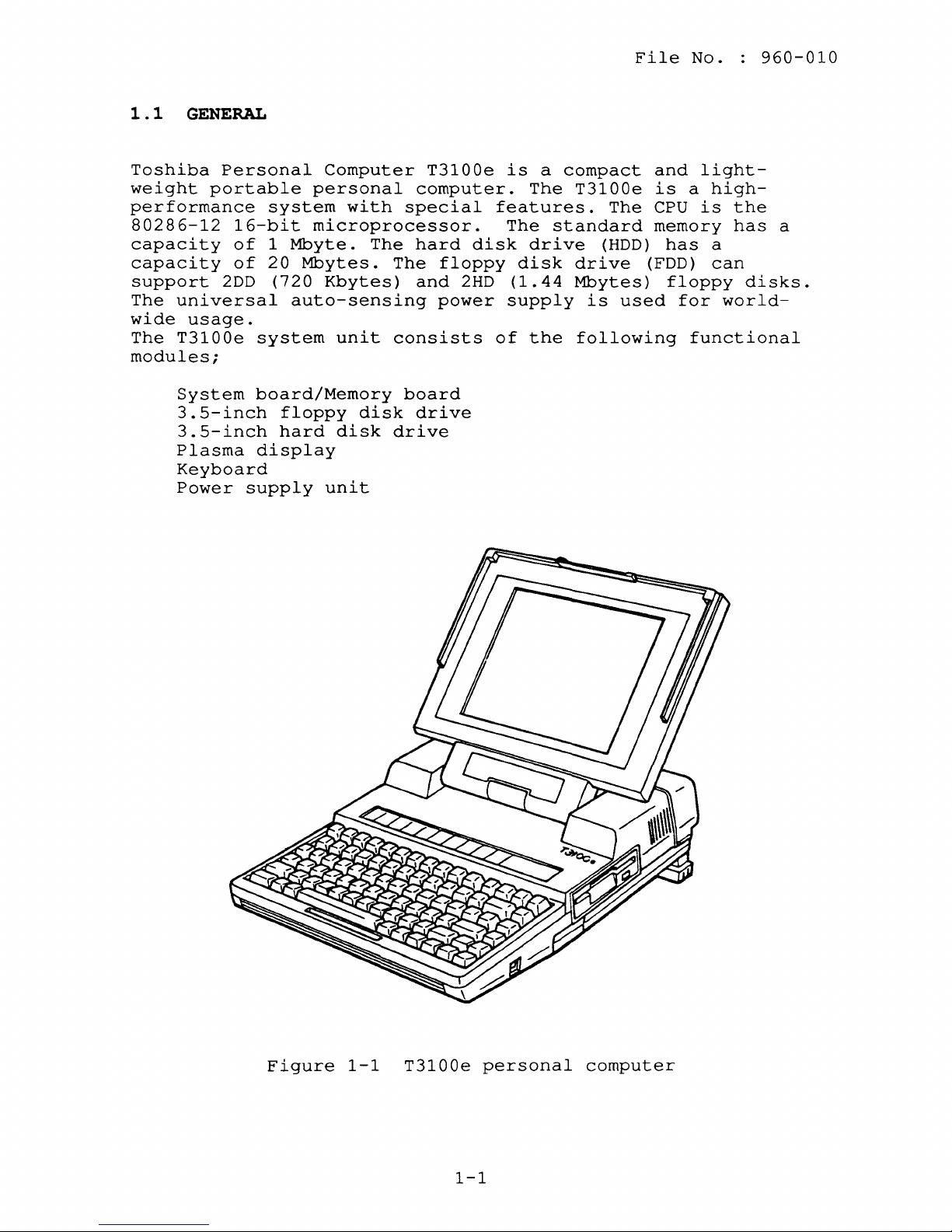
Figure
1-1
T3100e
1-1
personal
computer

hj
1-'-
\.Q
C
Ii
<1>
I-'
I
N
en
"<:
(J)
rt
<1>
I-'
S
I
N
C
::l
1-'-
rt
()
0
::l
HI
1-'-
lQ
c
Ii
~
rt
1-'-
0
::l
Plasma
Display
and
LED
Hard
Disk
Drive
and
Controller
Floppy
Disk
Drive
A-B-PRT
Switch
Optional
Memory
0
..........
Monochrome
Display
orl~----------~
Standard
Color
Display
PJ
15
PJ12
PJ6,
11
PJ8,9
S1
IS101,102
or
Printer
PJ
13
External
Floppy
Disk Drive
PJ2,10
System board
Memory
board
Two
Serial
Devices
_._._.-._._._.-._._._.-.,
............
Option
Card
•
000
OJ,:
0
0
00'
System
Unit
PJ2
PJ3,4
..................
PJ5
I
+-:
IBM
PC
compatible
0
card (8-Bit)
..................
PJ14
Cooling
Fan
PJ7
PJ1
PJ6
PJ3
L._._._._._._._._._._._._._._._._._._.
1-3
::T
<1>
()
0
::l
HI
1-'-
lQ
C
Ii
~
rt
1-'-
0
::l
0
HI
rt
::T
<1>
(J)
"<:
(J)
rt
<1>
S
C
::l
1-'-
rt
1-'-
(J)
(J)
::T
0
~
::l
1-'-
::l
HI
1-'-
lQ
C
Ii
<1>
I-'
I
N
....
II.)
en
I<
en
~
~
~
H
~
hj
1-'-
f-'
<1>
Z
o
\D
m
o
I
o
I-'
o
The
key
features
of
the
system
unit
are:
File
No.
960-010
o A
system
cables.
o An
2HD
2DD
The
Mbytes
respectively.
o A
20-Mbyte
o An
can
keyboard.
o
An
o A
universal
world-wide
power
including
power
power.
by
board
internal
(double-side,
(double-side,
2HD
and
and
internal
be
used
internal
to
all
the
supply
The
+12
VDC.
and
3.5-inch
high-density,
double-density,
2DD
floppy
720
Kbytes
3.5-inch
82-key
exactly
640
x
400
auto-sensing
provides
the
components
option
provides
power
supply's
memory
FDD
supporting
disks
of
storage
HDD
(hard
keyboard.
like
a
pixel
power
+5
VDC,
cards.
the
board
connected
double-track)
can
be
capacity,
disk
For
most
standard
plasma
supply
+12
VDC,
in
the
For
the
regulated
ventilation
by
two
media
double-track)
formatted
drive)
.
applications
typewriter
display.
that
-5
system
plasma
+205
fans
can
VDC
unit,
display,
and
are
2
types:
with
and
+5
flat
be
used
-12
VDC
driven
1.44
it
VDC
the
o A
o A
lithium
when
parallel
the
Red/Green/Blue
(CRT)
located
The
parallel
an
external
battery
system
printer
display,
on
the
and
system
printer
FDD
that
unit
(RGB)
unit
keeps
power
(or
floppy
direct
two
SERIAL
unit's
connector
by
the
is
drive
rear
changing
date
off.
disk
Cathode
device
panel
can
the
and
drive),
connectors,
and
be
used
A-B-PRT
time
Ray
right
to
even
Tube
side.
connect
switch.
1-3
hj
1-'-
I.Q
C
11
(I)
f-l
I
W
f-l
0;1
I
I-'
.b
0
()
~
0-
1-'-
~
I.Q
11
~
;3
~
OSC
24.0MHZ
14.7MHZ
14.3MHZ
17.5MHZ
19.2MHZ
16.0MHZ
32.7MHZ
NDP
i60287
IOPTlON)
CPU
i80286-12
A23-17
;\23-1);1,0
,..---
A23-11
D"-I
GA-DMAl
A23-11
)!
PJ3
.01.....
.01
.....
~
I r
SAl0-o
'''10...,
PJ4
~
501-0
d-RAM
$07-0
60PIN
COMMAND
82PIN
TRANS
1--..1
TRANS
74H08
1--,.:1
LS244
12MU)
"d-RAM
M44256
X8
M81100 X18
I-
11MB)
MD7-U
":
OPTION
hj
1-'-
\Q
C
11
(I)
f-l
I
W
Ul
::r
0
~
Ul
rt
::r
(I)
0'
f-'
0
()
X"
0.
1-'-
~
\Q
11
~
13
0
H1
rt
::r
(I)
Ul
I<:
Ul
rt
(I)
;3
0'
0
~
11
0.
.....
W
en
~
en
8
~
ttl
~
hj
1-'-
f-'
(I)
Z
o
\.D
m
o
I
o
f-l
o

File
No.
960-010
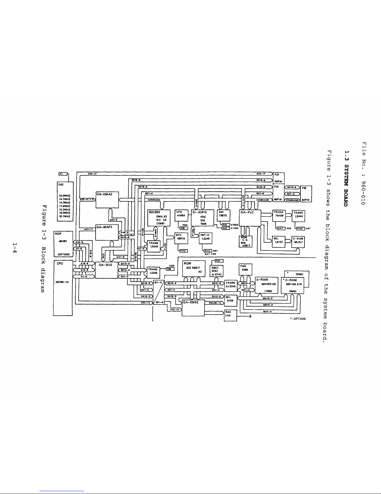
System
board
components:
System
o
board
Central
The
clock
o
Numeric
(optional)
Real
o
The
lithium
o
Serial
The
o
Variable
The
o
Two
SI
PIT
(82C37),
and
processing
CPU
is
speed.
data
time
RTC
continuously
battery.
input
SIO
controls
VFO
chip
super
(JC810)
(82C54).
memory
a
16-bit
processor
.
clock:
output:
frequency
is
integration:
includes
SI
two
PICs
board
unit:
microprocessor
socket
RTC
(MC146818)
keeps
SIO
the
RS232C
oscillator:
used
for
SI
the
FDC
(M5M82C800)
(82C59)
are
composed
CPU
(80286-12)
for
the
date
(TC8570)
port.
VFO
FDD
control
(JC810,
(TC8565),
includes
and
one
of
the
operated
the
80287-12
and
time
(MB4108A)
logic.
M5M82C800)
SIO
the
PIT
(TC8570),
two
(82C54).
following
at
12
powered
DMACs
MHz
by
and
o
Gate
The
See
information.
o
DMA
o
MAP
o
Bus
o PLC
arrays:
following
the
T3100e
controller
controller
controller
controller
gate
GATE
arrays
gate
gate
gate
gate
ARRAY
array
array
array
array
are
used
in
the
SPECIFICATION
DMA3-GA
MAP3-GA
BUS-GA
PLC-GA
(100
(100
(100
(100
system
MANUAL
pin)
pin)
pin)
pin)
board.
for
more
1-5
File
No.
960-010
Memory
o
Keyboard
o Memory
Random
Read
o
Gate
The
See
information.
EMS
board
only
array
following
the
controller
controller:
access
memory : RAM 1 Mbyte
memory : ROM
gate
T3100e
GATE
gate
KBC
array
ARRAY
array
64
(8742
Kbytes
is
or
used
SPECIFICATION
: EMS2-GA
8042)
(system
in
the
(100
BIOS)
memory
MANUAL
pin)
board.
for
more
1-6
File
No.
960-010
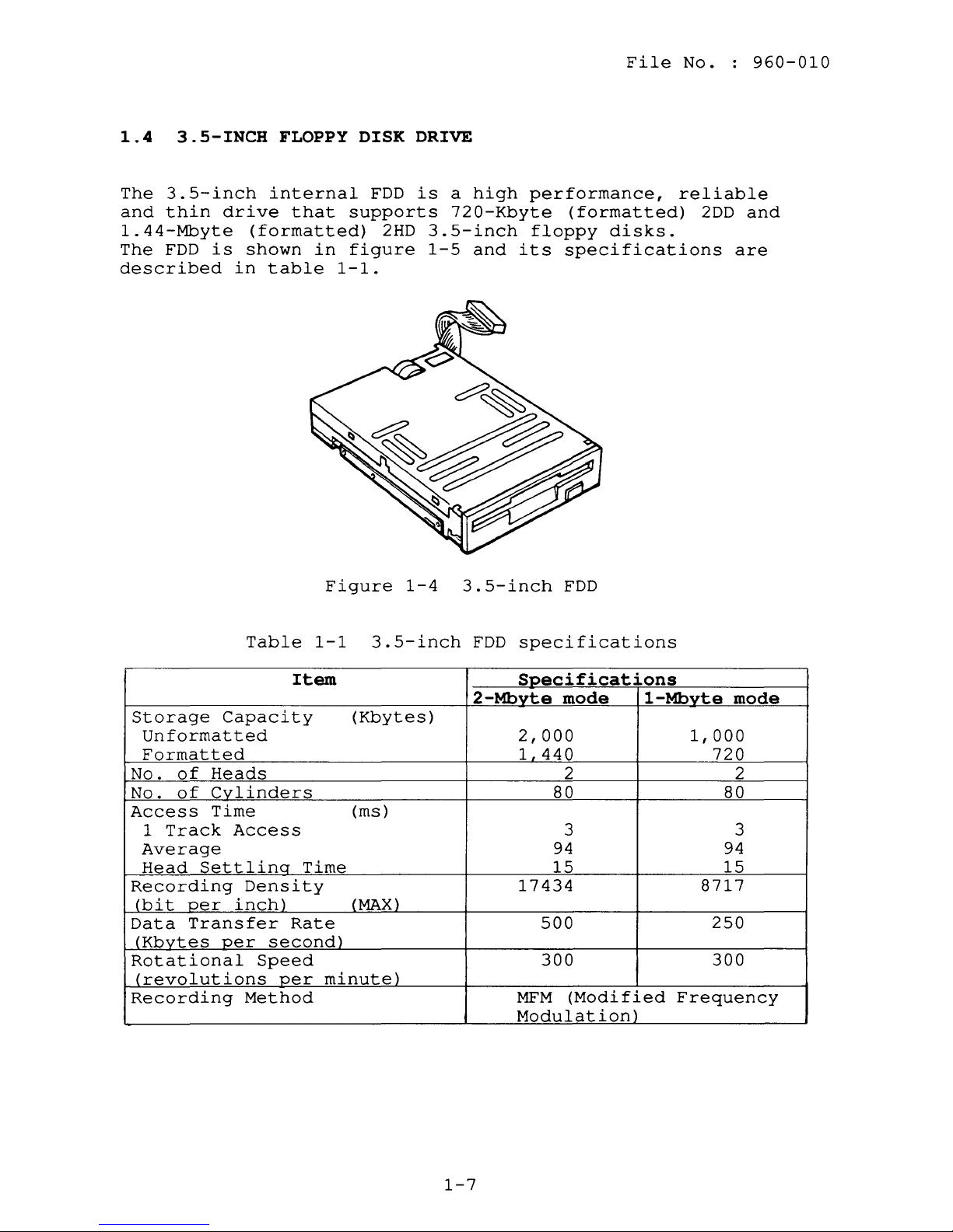
1.4
The
and
3.5-INCH
3.5-inch
thin
1.44-Mbyte
The
FDD
described
drive
(formatted)
is
shown
in
FLOPPY
internal
that
in
table
Figure
DISK
FDD
supports
2HD
figure
1-1.
DRIVE
is
3.5-inch
1-5
1-4
a
high
720-Kbyte
and
its
3.5-inch
performance,
(formatted)
floppy
disks.
specifications
FDD
reliable
2DD
and
are
Storage
Unformatted
Formatted
No.
of
Heads
of
No.
Access
1
Cylinders
Time
Track
Average
Head
Settlinq
Recording
(bi t per
Data
Transfer
(Kbytes
Rotational
(revolutions
Recording
Table
Capacity
Access
Density
inch)
per
second)
Speed
per
Method
1-1
Item
Time
Rate
3.5-inch
(Kbytes)
(ms)
(MAX)
minute)
FDD
specifications
Specifications
2-Mbvte
2,000
1
440
17434
500
300
MFM
Modulation)
mode
1-Mbvte
mode
1,000
720
2 2
80 80
3 3
94
15
94
15
8717
250
300
(Modified
Frequency
1-7
File
No.
960-010
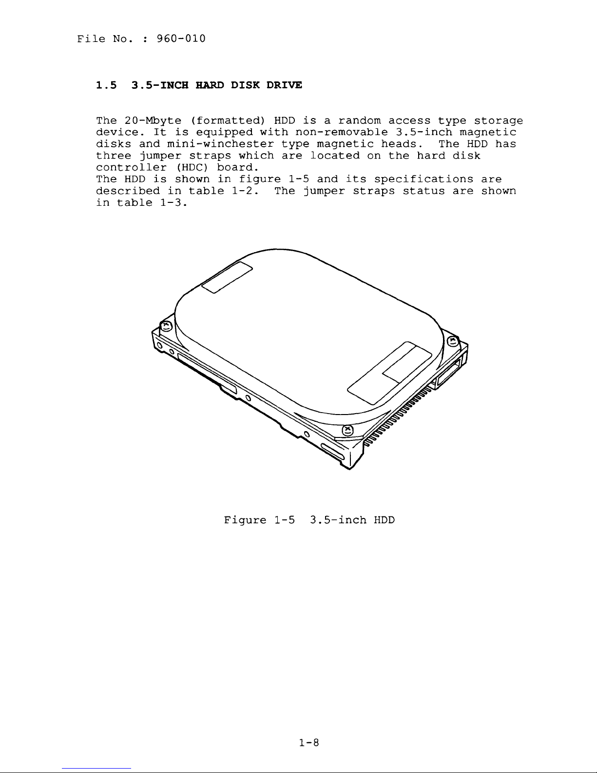
1.5
The
3.5-INCH
20-Mbyte
device.
disks
three
and
jumper
controller
The
HDD
described
in
table
HARD
(formatted)
It
is
equipped
mini-winchester
straps
is
(HDC)
shown
in
board.
in
table
1-3.
DISK DRIVE
HDD
with
non-removable
type
which
figure
1-2.
are
1-5
The
is
a
magnetic
located
and
jumper
random
on
its
straps
access
type
3.5-inch
heads.
the
The
hard
specifications
status
storage
magnetic
HDD
disk
are
are
shown
has
Figure
1-5
3.5-inch
1-8
HDD

File
No.
960-010
Table
1-2
3.5-inch
Item
Storage
Formatted
Number
Data
Data
Tracks
Track
Track
Formatted
Sectors
Access
Capacity
of
Surfaces
Heads
per
Density
Capacity
per
Physical
User
Sectors
Time
Track
(Mbytes)
Disks
Surface
:
(bytes)
Track
Sectors
(ms)
to
Track
:
(tpi)
:
(bps)
Average
Maximum
Rotation
Data
To/From
To/From
Start
I
Transfer
(0-3575RPM):
Speed
Time
Rate
Media
Buffer
(rpm)
(bps)
(s)
Typical
I Maximum
I (0 RPM-READY):
Typical
I Maximum
I
Stop
Time
(s)
Typical
I Maximum
I
Interleave
1
____________________________
IRecording
1
________________________________
IRecording
Method
Density
(ID)
(bpi)
HDD
specifications
Specifications
20-Mbyte
21.4
1
2
2
636
1,150
16,896
34
33
8
27
50
3,575
1.
25
M
M
4
5
10
7
15
5
10
CP3022
~C~P~3~0~2~4~~1~~~
2-7
RLL
L-
__
~(~R~u~n~L~e~n~g~t~h~L~i~m~l~·t~e~d~)
21,
594
1 1 : 1
3
1
code
40-Mbyte
42.8
1
2
2
1,
047
1,
400
20,480
41
40
8
25
50
3,557
M
1.5
4.5
M
5
10
7
15
5
10
____________
____
I
30,871
__
_
Table
20-Mbyte
I
Signal
E5
I
E6
I
E7
I
(CP3022
I
I
I
I
Status
Short
Open
Short
)
1-3
HDD
jumper
20-Mbyte
ISignall
HSP
C/D
DHP
ACT
1-9
strap
status
(CP3024)
Status
Open
Short
Open
Short
or
40-Mbyte
File
No.
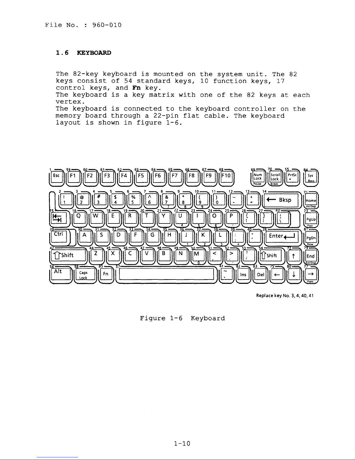
1 . 6 KEYBOARD
The
82-key
keys
consist
control
The
keyboard
vertex.
The
keyboard
memory
board
layout
960-010
keys,
is
shown
keyboard
of
54
and
is
a
is
connected
through
in
is
standard
Fn
key.
key
matrix
a
figure
mounted
keys,
to
22-pin
1-6.
on
with
the
flat
the
system
10
function
one
of
keyboard
cable.
unit.
keys,
the
82
controller
The
keyboard
keys
The
17
at
on
82
each
the
Figure
1-6
1-10
Keyboard
Replace key
No.3,
4,
40,
41
File
No.
960-010
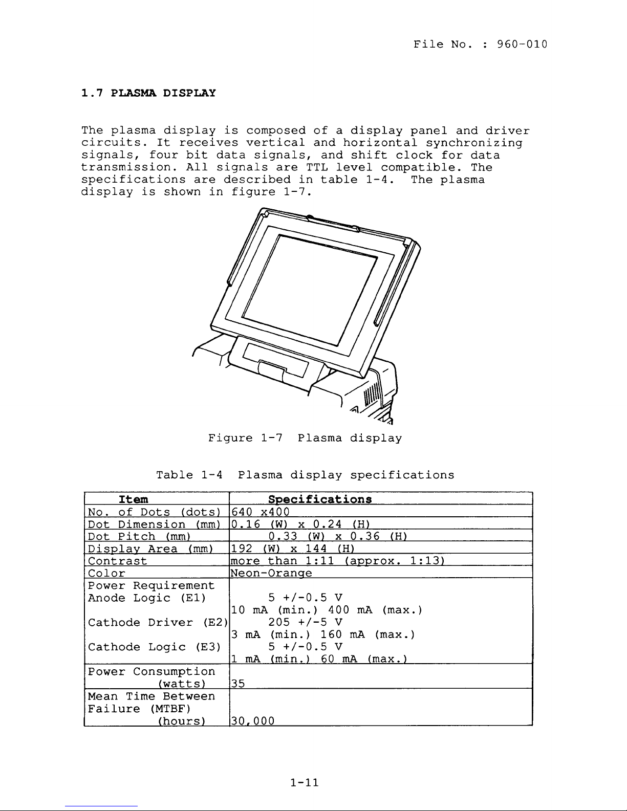
1 . 7 PLASMA
The
plasma
circuits.
signals,
four
transmission.
specifications
display
is
DISPLAY
display
It
receives
bit
All
are
shown
is
data
signals
described
in
figure
composed
vertical
signals,
are
1-7.
TTL
in
of
and
and
table
a
display
horizontal
shift
level
1-4.
panel
synchronizing
clock
compatible.
The
and
for
data
The
plasma
driver
Item
No.
Dot
Dot
of
Dimension
Pitch
DisPlav
Contrast
Color
Power
Anode
Cathode
Cathode
Power
Mean
Time
Failure
Table
Dots
(dots)
(mm)
(mm}
Area
(mm)
Requirement
Logic
(E1 )
Driver
Logic
(E3 ) 5
Consumption
(watts)
Between
(MTBF)
(hours)
Figure
1-4
Plasma
640
o .
192
more
Neon-Oranqe
10
(E2)
3
1
35
30.000
1-7
display
Specifications
x400
16
(W)
0.33
(W)
x
than
5
+/-0.5
(min.
rnA
205
(min. ) 160
rnA
+/-0.5
(min.
rnA
Plasma
x
0.24
(W)
144
1:11
)
400
+/-5
)
60 rnA
display
specifications
(H)
x
0.36
(H)
(approx.
V
rnA
(max.
V
rnA
(max.
V
(max.)
(H)
1:13)
)
)
1-11

File
1
.8
The
wide
system.
The
supplies
1)
2)
3)
4)
5)
6)
7)
The
the
The
fuse,
connectors.
Input
85
rating
The
ratings
No.
POWER
universal
and
power
System
Memory
3.5-inch
3.5-inch
Plasma
Option
Cooling
above
power
power
cooling
ratings
to
138
power
960-010
SUPPLY
supplies
supply
the
2)
via
supply
VAC
is
115
supply
are
UNIT
auto-sensing
+5,
unit
regulated
board
board
floppy
hard
display
boards
fans
through
the
system
unit
fan,
are:
or
170
VAC,
unit
specified
-5,
is
power
disk
disk
drive
4),
includes
power
to
276
60 Hz) .
is
in
power
+12,
housed
-12
in
to:
drive
6)
and
one
board.
an
conversion
VAC,
shown
table
in
1-5.
supply
and
the
of
input
circuitry
less
figure
can
+205
system
cooling
line
than
1-8
be
VDC
filter,
130
and
used
to
unit
fans
and
W
world-
the
and
receive
(when
the
it
line
input
output
Figure
1-8
Power
1-12
supply
unit
File
No.
960-010
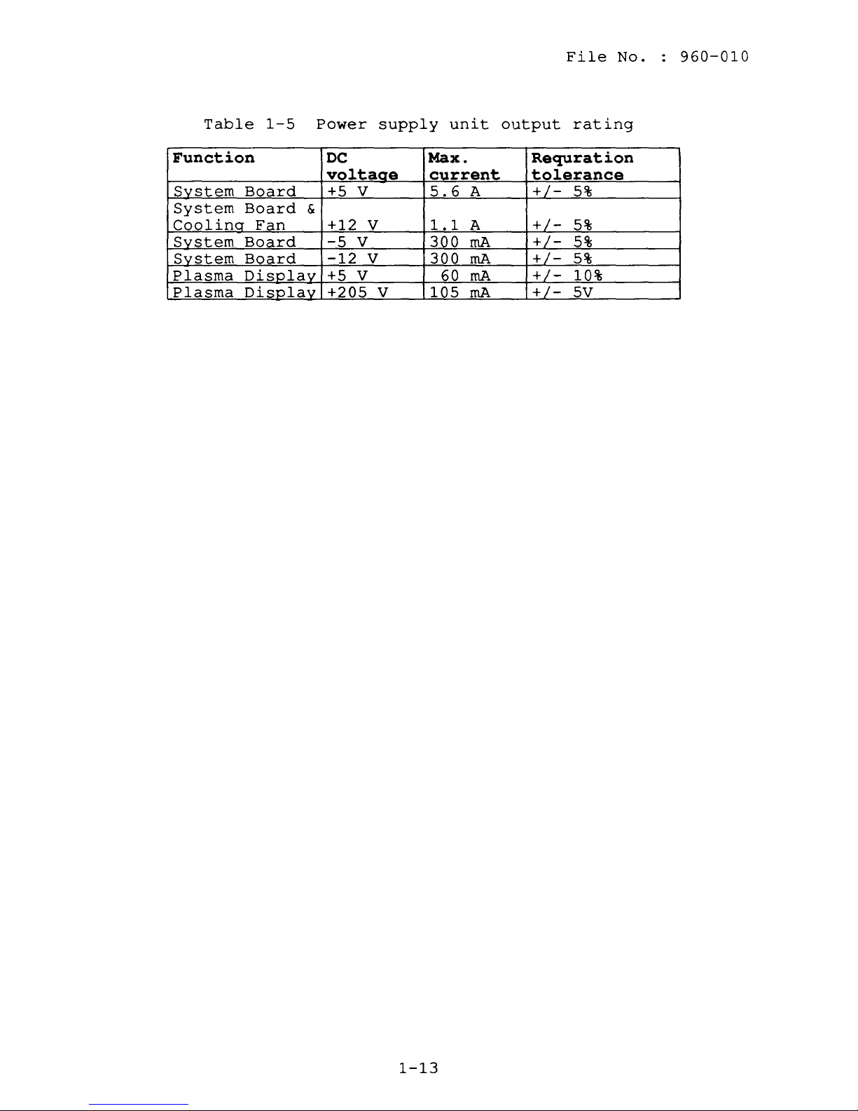
Table
Function
SYstem
System
Coolina
System
System
Plasma
Plasma
1-5
Board
Board
Fan
Board
Board
Displav
Displav
Power
DC
voltaae
+5 V
&
+12
-5
-12
+5 V
+205
V
V
V
supply
V
unit
Max.
current
5.6
A
A
1.1
300
rnA
rnA
300
rnA
60
105
rnA
output
Requration
tolerance
+/+/-
+/+/+/+/-
rating
5%
5%
5%
5%
10%
5V
1-13

File
No.
960-010
1-14
2.1
The
used
The
GENERAL
problem
to
isolate
FRUs
1.
2.
3.
4.
5.
6.
covered
Power
System
FDD
HDD
Keyboard
Plasma
isolation
defective
are:
supply
board
display
procedures
FRUs
unit
described
(field
File
in
replaceable
part
No.
2
units)
960-010
are
.
Detailed
in
part
described
The
following
problem
1.
2.
3.
4.
5.
6.
7.
8.
The
problem
be
used
necessary
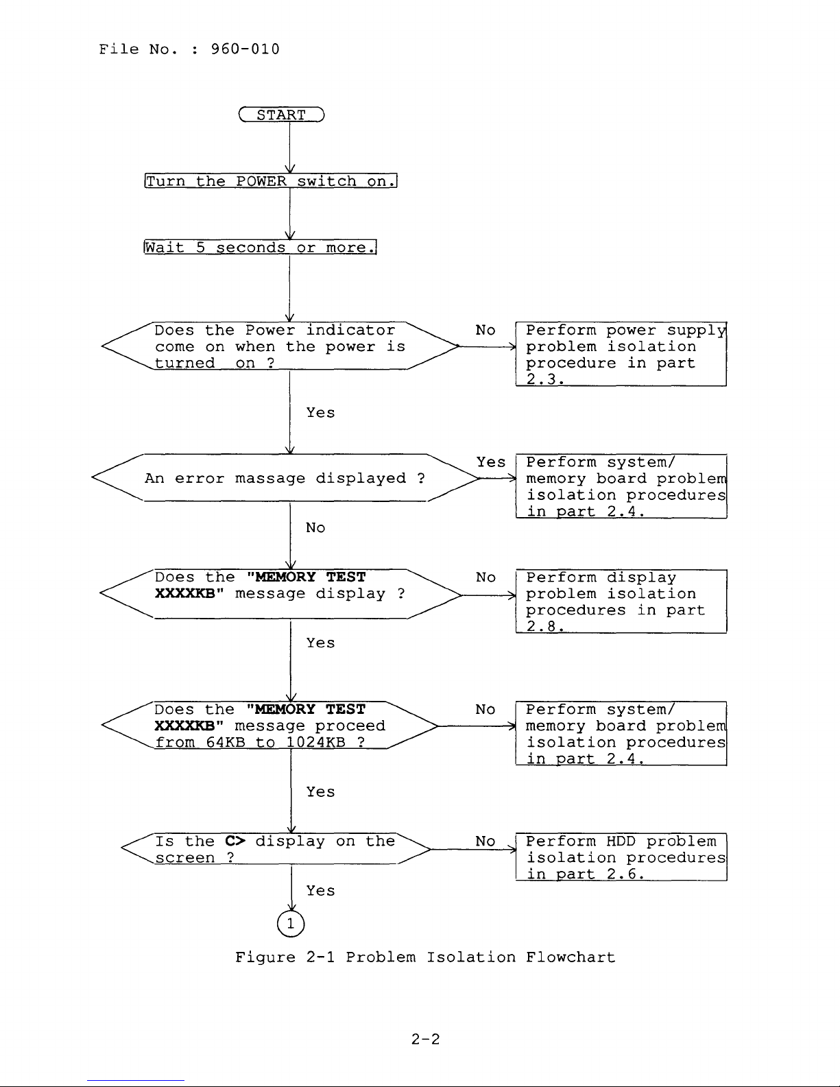
2.2
PROBLEM
The
flowchart
determining
followings
replacement
4
and
test
in
part
items
isolation
T3100e
Phillips
Blade
Tweezers
2DD
and
Cleaning
Multimeter
Printer
isolation
to
determine
to
isolate
ISOLATION
in
which
before
procedures
and
3.
are
procedures.
diagnostics
head
head
screwdriver
2HD
formatted
disk
port
flowchart
which
a
FLOWCHART
figure
FRU
is
performing
diagnostics
necessary
disk
screwdriver
kit
(for
LED
isolation
T3100e
2-1
problem.
is
defective.
the
instructions
program
for
work
FDD
disk
testing)
described
procedures
used
as
Please
flowchart
are
operations
implementing
a
(for
in
guide
FDD
section
for
confirm
procedures.
described
the
testing)
2.2
are
the
are
can
1.
2.
3.
No
disk
All
optional
MS-DOS
trouble
is
in
has
been
happens.
the
FDD.
equipments
installed
2-1
are
disconnected.
in
drive
C
before
a
File
No.
960-010
START
Turn
Wait
Does
come
turned
~
~Does
An
XXXXKB"
the
5
error
POWER
seconds
the
on
when
on?
massage
the
message
switch
or
Power
indicator
the
Yes
No
,j
"MEMORY
Yes
on.
more.
power
displayed
TEST
display
is
?
2
No
Yes
No
Perform
problem
procedure
2.3.
Perform
memory
board
isolation
in
part
Perform
problem
procedures
2.8.
power
isolation
in
part
system/
proble
procedures
2 . 4 .
display
isolation
in
suppl
part
message
64KB
C>
?
"MEMORY
to
display
<IS
Does
XXXXKB"
the
from
the
screen
~yes
Figure
/
TEST
proceed
1024KB
Yes
on
2-1
?
the
Problem
Isolation
2-2
No
No
Perform
memory
isolation
in
Perform
....
isolation
in
Flowchart
part
part
system/
board
procedures
2.4.
HDD
procedures
2.
6.
problem
problem
File
No.
960-010
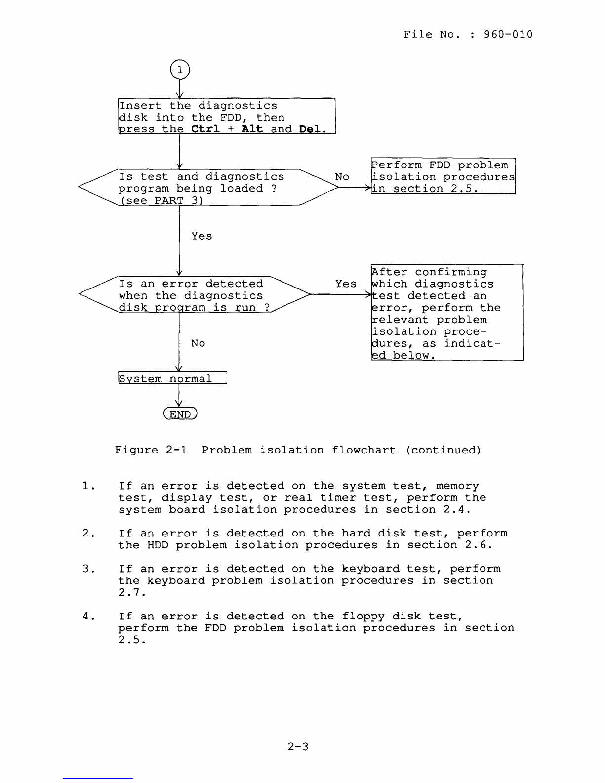
Insert
isk
into
ress
Is
test
program
see
PART
Is
an
when
the
disk
the
the
the
Ctrl
and
being
3
Yes
error
diagnostics
ro
ram
No
diagnostics
FDD,
+
Alt
diagnostics
loaded
detected
is
run?
then
and
?
Del.
erform
No
isolation
in
fter
Yes
~------~~est
hich
rror,
elevant
isolation
ures,
d
section
confirming
diagnostics
detected
perform
as
below.
FDD
problem
procedures
2.5.
problem
proce-
indicat-
an
the
1.
2.
3.
4.
Figure
If
an
test,
system
If
an
the
HDD
If
an
the
keyboard
2.7.
If
an
perform
2.5.
2-1
error
display
board
error
problem
error
error
the
Problem
is
detected
test,
isolation
is
detected
isolation
is
detected
problem
is
detected
FDD
problem
isolation
on
or
real
procedures
on
on
isolation
on
isolation
flowchart
the
system
timer
the
hard
procedures
the
keyboard
procedures
the
floppy
(continued)
test,
test,
in
section
disk
in
perform
test,
section
test,
disk
procedures
memory
2.4.
in
section
test,
in
the
perform
2.6.
perform
section
2-3
File
2.3
No.
POWER
960-010
SUPPLY UNIT
PROBLEM
ISOLATION
PROCEDURES
WARNING:
supply
few
This
power
unit.
minutes
section
supply
continue
procedures
Dangerous
Pay
after
describes
unit
with
other
described
PROCEDURE
PROCEDURE
PROCEDURE
PROCEDURE
high
enough
power
how
is
defective.
procedures
in
1:
2:
3:
4:
voltage
attention
off
to
to
this
section
Power
Connector
Output
Power
is
supplied
on
discharge
determine
Start
as
instructed.
Indicator
Check
Voltage
Supply
handling.
the
whether
with
are:
Check
Check
Unit
to
the
It
electricity.
or
not
PROCEDURE
The
Replacement
power
takes
the
1
and
2-4
File
No.
960-010
Power
1.
2.
Indicator
Turn
If
If
cord
on
the
the
connection.
inserted
should
the
system
If
OK,
After
lights,
the
indicator
Check
the
power.
power
indicator
the
be
connected
unit.
replace
replacing
the
original
indicator
does
One
standard
the
the
still
PROCEDURE
lights,
not
light,
end
of
AC
wall
to
the
AC
AC
power
AC
power
cord
was
doesn't
1
go
the
outlet
IN
cord.
cord,
probably
light,
to
check
AC
jack
PROCEDURE
the
power
if
and
on
the
cord
the
the
defective.
go
to
PROCEDURE
3.
AC
power
should
other
back
indicator
be
end
of
If
2.
2-5
File
No.
960-010
Connector
1.
2.
3.
4.
Turn
Remove
Remove
If
is
connected
Check
off
the
the
the
the
power
connected
power,
top
cover.
power
supply
properly,
properly,
PROCEDURE
then
(Refer
supply
connector
go
reconnect
unplug
unit.
to
2
the
AC
to
section
(Refer
(PJ7)
on
PROCEDURE
it.
power
to
the
3.
cord.
4.8.)
section
system
If
it
4.9.)
board
is
not
2-6
File
No.
960-010
Output
1.
2.
3.
4.
Voltage
Plug
turn
Use
for
the
on
a
multimeter
the
values
If
the
table
2-1,
system
board
If
isolation
the
values
Table
Connector
Check
AC
power
the
power.
two
power
given
voltages
the
board
voltages
given
2-1
Pin
+lead
to
in
table
are
power
is
probably
procedures
are
in
table
Power
number
-lead
PROCEDURE
cord
to
confirm
supply
connectors
2-1.
within
supply
defective.
still
2-1,
supply
Normal
the
the
in
not
go
unit
3
power
that
unit
section
within
to
supply
the
output
conform
range
is
of
normal,
Go
the
PROCEDURE
output
Voltage
Min
values
to
2.4.
range
voltages
(Vdc)
unit,
voltages
to
the
given
but
the
system
of
4.
Max
then
in
the
For
system
board
For
plasma
display
For
cooling
fan
1
2,5,
2,5,6
3
4
2,5,6
8
2,5,6
1 4
6
12
-12
-5
5
205
5 4 5
1
2
12
11.4
-12.6
-11.4
-5.25
4.75
200 210
4.5
11.4
12.6
-4.75
5.25
5.5
12.6
2-7
File
No.
960-010
Power
1.
2.
3.
4.
Supply
Turn
off
Replace
If
normal
power
probably
If
normal
probably
isolated
Unit
the
the
operation
supply
defective.
operation
defective.
and
PROCEDURE
Replacement
power,
power
unit,
supply
the
replaced.
then
is
is
The
unplug
unit.
restored
original
not
restored,
defective
4
(Refer
the
after
power
unit
AC
power
to
replacing
supply
another
section
must
cord.
unit
FRU
be
4.9.)
the
was
is
2-8
2.4
SYSTEM
BOARD
PROBLEM
ISOLATION
File
PROCEDURES
No.
960-010
CAUTION:
sure
with
This
system
that
a
floppy
section
board
continue
procedures
Before
the
FDD
disk
describes
is
defective.
with
other
described
PROCEDURE
PROCEDURE
PROCEDURE
PROCEDURE
carrying
is
empty.
in
the
procedures
in
1:
2:
3:
4:
out
FDD
how
this
Message
Printer
Test
System
any
Performing
may
to
determine
Start
as
section
Program
Board
of
these
result
with
instructed.
are:
Check
Port
LED
Execution
Replacement
procedures,
these
in
whether
procedures
loss
of
or
data.
not
PROCEDURE 1 and
The
Check
make
the
2-9
File
No.
960-010
Message
1.
2.
3.
Turn
If
If
press
the
Check
on
the
the
the
section
***
Check
***
Check
***
Check
the
power.
system
following
Fl
key.
3
Error
system.
Error
system.
Error
system.
is
for
in
in
in
PROCEDURE
loaded
message
Execute
details.)
CMOS.
Then,
CMOS.
Then,
CMOS.
Then,
1
normally,
is
displayed
the
setup
Bad
battery
press
Bad
check
press
Bad
configuration
press
go
[Fl]
sum
[Fl]
[Fl]
to
PROCEDURE
on
the
operation.
***
key
***
key
key
.....
.....
3.
screen,
(See
**
4.
If
the
turn
on
the
again,
***
Error
Check
***
Error
Check
following
off
the
power.
go
Insert
Press
system.
system.
power.
to
HDD
system
any
in
CMOS.
in
CMOS.
message
If
the
isolation
key
Then,
Then,
Wait
following
disk
when
Bad
memory
press
Bad
time
press
is
displayed
5
seconds
procedures
in
drive
ready
[Fl]
function
[Fl]
message
.....
size
key
key
or
***
.....
.....
on
the
more,
is
in
section
**
screen,
then
displayed
turn
2.6.
2-10
File
No.
960-010
5.
6.
If
the
the
system
following
system
setup
configuration.
following
5 .
Video
CRTC
If
the
to
PROCEDURE
CPU
KBC
KBC
KBC
KBC
CPU
ROM
PIT
CMOS
DMA
DMA
DMA
Memory
1st
Error
Error
VRAM
Memory
Memory
Error
Error
Error
Error
Error
Memory
Memory
Error
Refresh
Error
First
LIM
following
flag
register
IBF/OBF
IBF
error
self
OBF
test
error
register
checksum
channel
shutdown
channel
channel
page
register
refresh
64KB memory
interrupt
interrupt
error
verify
parity
interrupt
interrupts
interrupts
protect
sizing
verify
verify
processor
timing
encountered
64KB memory
page
register
may
not
menu
message
RAM
error
error
4.
error
error
error
error
2
error
byte
0
error
1
error
error
error
error
mode
expansion
error
error
error
message
be
set
and
select
(see
the
is
displayed
message
error
error
error
error
controller
controller
at
X:X
at
X:X
and
stuck
and
and
stuck
stuck
...
memory
at
X:X:X
at
X:X:X
exceptional
initializing
error
error
is
displayed
up
the
part
is
displayed
1
2
found
found
NMI
NMI
NMI
found
found
interrupts
correctly.
appropriate
3
for
again,
X
expanded
X
expected
X
X
hard
on
the
Go
details.)
go
on
the
expected
expected
...
drive
screen,
to
system
to
PROCEDURE
screen,
X
X
X
X
the
If
the
go
7.
If
have
none
a
of
the
printer
above
port
messages
LED,
go
2-11
are
to
PROCEDURE
displayed
2.
and
you
File
No.
960-010
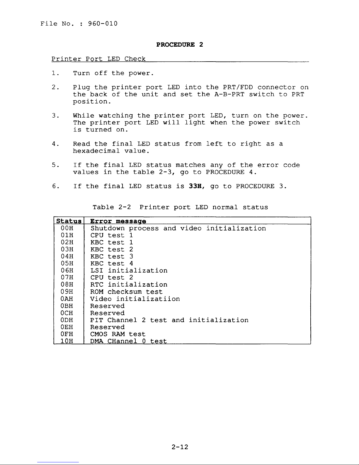
Printer
1.
2.
3.
4.
5.
6.
Port
Turn
Plug
the
LED
off
the
back
position.
While
The
is
Read
watching
printer
turned
the
hexadecimal
If
the
values
If
the
final
in
final
Table
Check
the
power.
printer
of
the
port
on.
final
value.
LED
the
LED
2-2
unit
the
LED
table
Printer
PROCEDURE
port
LED
and
printer
LED
will
status
status
2-3,
status
port
into
set
the
port
light
from
matches
go
to
is
33B,
LED
2
the
PRT/FDD
A-B-PRT
LED,
when
left
any
to
of
PROCEDURE
go
to
normal
connector
switch
turn
the
on
power
right
the
error
4.
PROCEDURE
status
the
as
to
PRT
power.
switch
a
code
3.
on
Status
OOH
01H
02H
03H
04H
05H
06H
07H
OSH
09H
OAR
OBH
OCH
ODH
OEH
OFH
10H
Error
messaae
Shutdown
CPU
test
KBC
test
KBC
test
KBC
test
KBC
test
LSI
CPU
RTC
ROM
Video
initialization
test
initialization
checksum
initializatiion
Reserved
Reserved
PIT
Channel
Reserved
CMOS
DMA
RAM
CHannel
process
1
1
2
3
4
2
test
2
test
0
test
test
and
and
video
initialization
initialization
2-12
File
No.
960-010
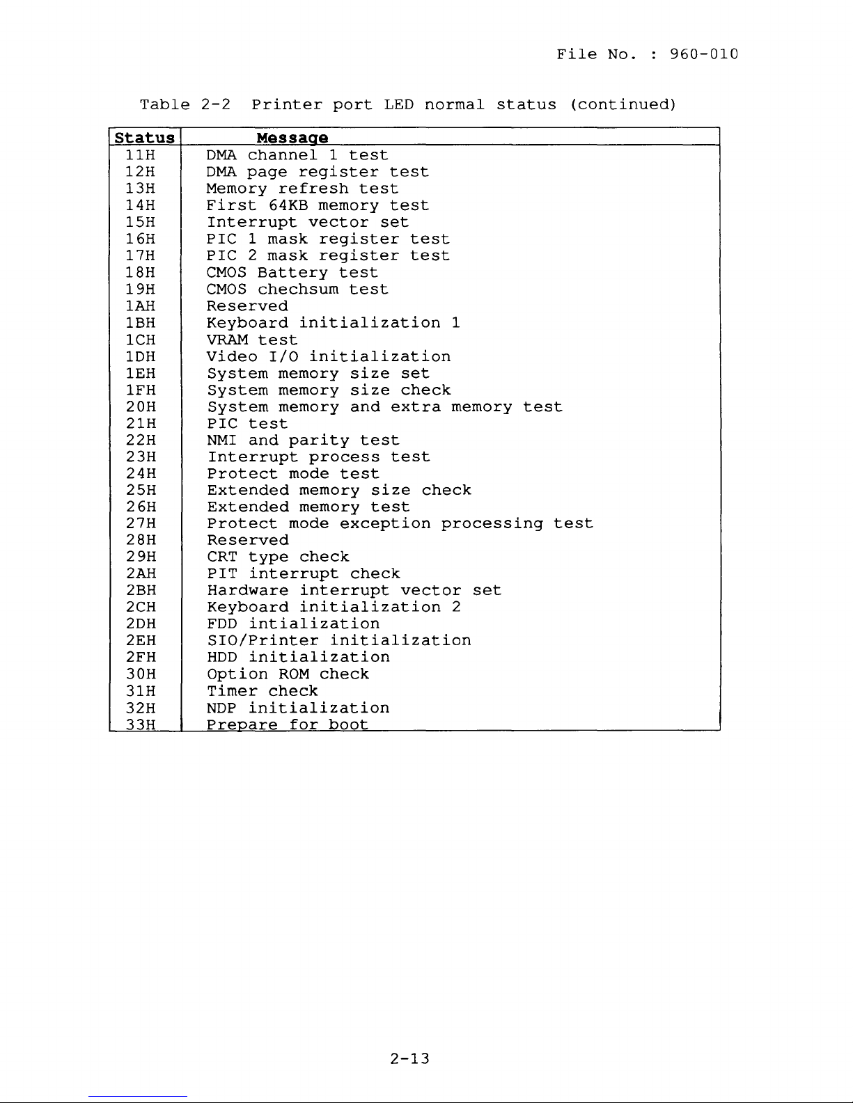
Table
Status
11H
12H
13H
14H
15H
16H
17H
18H
19H
1AH
IBH
lCH
1DH
1EH
1FH
20H
21H
22H
23H
24H
25H
26H
27H
28H
29H
2AH
2BH
2CH
2DH
2EH
2FH
30H
31H
32H
33H
2-2
Printer
Messaae
DMA
DMA
Memory
First
PIC
PIC
CMOS
CMOS
Reserved
Keyboard
VRAM
Video
NDP
Prepare
channel
page
64KB
Interrupt
1
mask
2
mask
Battery
chechsum
test
I/O
System
System
System
PIC
test
NMI
and
Interrupt
Protect
Extended
Extended
Protect
Reserved
CRT
type
PIT
interrupt
Hardware
Keyboard
FDD
intialization
SIO/Printer
HDD
initialization
Option
Timer
check
initialization
port
1
register
refresh
memory
vector
register
register
test
initialization
initialization
memory
memory
memory
parity
process
mode
test
memory
memory
mode
exception
check
interrupt
initialization
initialization
ROM
for
check
boot
LED
test
test
set
test
size
size
and
test
size
test
check
test
test
test
test
set
check
extra
test
vector
normal
1
memory
check
processing
set
2
status
test
(continued)
test
2-13

File
No.
960-010
Status
81H
82H
83H
84H
85H
87H
89H
8DH
8FH
90H
91H
92H
93H
94H
96H
97H
9CH
AOH
A1H
A2H
A3H
A4H
A5H
A6H
A7H
AAH
AFH
D4H
EOH
Table
Error
CPU
flag
KBC
IBF/OBF
KBC
IBF
KBC
self
KBC
OBF
CPU
register
ROM
checksum
PIT
CMOS
DMA
DMA
DMA
channel
shutdown
channel
channel
page
Memory
1st
64KB
Error
Error
VRAM
error
Memory
found
Error
Error
Error
Error
Error
Memory
found
Memory
found
Error
Refresh
Error
hard
drive
First
LIM
paqe
2-3
Printer
messaae
register
error
error
test
error
error
error
2
0
1
register
refresh
memory
interrupt
interrupt
verify
X
expanded
interrupt
interrupts
interrupts
protect
sizing
expansion
verify
X
expected
verify
X
expected
processor
timing
encountered
64KB
memory
reqister
error
error
error
byte
error
error
error
error
error
error
controller
controller
error
X
and
and
and
mode
...
error
X
error
exceptional
error
initializing
error
error
port
at
stuck
stuck
stuck
at
at
LED
1
2
X:X
NMI
NMI
NMI
memory
X:X:X
X:X:X
error
interrupts
status
...
Process
halt
halt
halt
halt
halt
halt
halt
halt
halt
halt
halt
halt
halt
halt
halt
Continue
halt
Continue
Continue
Continue
Continue
Continue
Continue
Continue
Continue
Continue
Continue
halt
Continue
2-14
File
No.
960-010
Test
1.
2.
3.
Program
Execute
Menu.
1.
2.
3.
4.
5.
6.
7.
8.
9.
If
an
test,
to
PROCEDURE
If
an
to
FDD
Execution
the
(Refer
System
Memory
Keyboard
Display
Floppy
Printer
ASYNC
Hard
Real
error
Printer
error
problem
following
to
Part
test
test
test
disk
test
test
disk
timer
is
detected
test,
4.
is
detected
isolation
PROCEDURE
tests
3
Test
test
test
test
test
during
ASYNC
test,
during
procedures
3
on
the
and
Diagnostics.)
the
or
the
Diagnostic
system
real
floppy
in
test,
timer
disk
section
Test
memory
test,
test,
2.5.
go
go
4.
5.
6.
If
an
error
to
HDD
If
an
error
keyboard
If
an
error
display
is
problem
is
problem
is
problem
detected
isolation
detected
isolation
detected
isolation
during
procedures
during
procedures
during
procedures
the
the
the
hard
in
disk
section
keyboard
in
display
in
section
test,
test,
section
test,
2.6.
2.7.
go
2.8.
go
go
to
to
2-15
File
No.
960-010
System
1.
2.
3.
Board
Replace
If
normal
system
defective.
If
normal
probably
isolated
replaced.
Replacement
the
system
operation
board,
the
operation
defective.
by
the
PROCEDURE
board.
is
original
is
The
test
and
(Refer
restored
system
not
restored,
defective
diagnostics
4
to
after
board
section
replacing
another
unit
program
is
must
4.16.)
the
probably
FRU
be
and
is
2-16
 Loading...