


T300MV2®/MTX®/MTX2
®
MEDIUM VOLTAGE
ADJUSTABLE SPEED MOTOR DRIVE
INSTRUCTION MANUAL
TOSHIBA INTERNATIONAL CORPORATION
Document Number: IF08CZ10
April, 2019

TOSHIBA INTERNATIONAL CORPORATION
13131 WEST LITTLE YORK
HOUSTON, TEXAS 77041
Tel: 1-713-466-0277
1-800-231-1412
Printed in U.S.A.
IF08CZ10 April, 2019 - ii -

Important Notice
The instructions contained in this manual are not intended to cover all details or variations in
equipment types, nor may it provide for every possible contingency concerning the installation, operation, or
maintenance of this equipment. Should additional information be required contact your Toshiba
representative.
The contents of this manual shall not become a part of or modify any prior or existing agreement,
commitment, or relationship. The sales contract contains the entire obligation of Toshiba International
Corporation. The warranty contained in the contract between the parties is the sole warranty of Toshiba
International Corporation and any statements contained herein do not create new warranties or modify the
existing warranty.
Any electrical or mechanical modifications to this equipment without prior written consent of
Toshiba International Corporation will void all warranties and may void the UL/CUL listing or other
safety certifications. Unauthorized modifications may also result in a safety hazard or equipment
damage.
Misuse of this equipment could result in injury and equipment damage. In no event will
Toshiba Corporation be responsible or liable for either indirect or consequential damage or injury
that may result from the misuse of this equipment.
TOSHIBA INTERNATIONAL CORPORATION
Adjustable Spe ed D rive
Please complete th e Warra nty Card suppl ied w ith the ASD and retu r n it to Tos h iba by prep aid ma il. This w ill
activate the 12 month warranty from the date of installation; but, shall not exceed 18 months from the date of
purchase.
Complete the following information about the drive and r etain it for your records.
Model Number:
Serial Number:
Project Number (if applicable):
Date of Installation:
Inspected By:
Name of Application:
IF08CZ10 April, 2019 - iii -

Manual’s Purpose and Scope
This manual provides information on how to safely install, operate, and maintain your TIC power
electronics product. This manual includes a section of general safety instructions that describes the warning
labels and symbols that are used throughout the manual. Read the manual completely before installing,
operating, or performing maintenance on this equipment.
This manual and the accompanying drawings should be considered a permanent part of the
equipment and should be readily available for reference and review. Dimensions shown in the manual are in
metric and/or the English equivalent.
Toshiba International Corporation reserves the right, without prior notice, to update information,
make product changes, or to discontinue any product or service identified in this publication.
TOSHIBA is a registered trademark of the Toshiba Corporation. All other product or trade
references appearing in this manual are registered trademarks of their respective owners.
Toshiba International Corporation (TIC) shall not be liable for direct, indirect, special, or
consequential damages resulting from the use of the information contained within this manual.
This manual is copyrighted. No part of this manual may be photocopied or reproduced in any form
without the prior written consent of Toshiba International Corporation.
© Copyright 2015 Toshiba International Corporation.
All rights reserved.
Printed in the U.S.A.
Contacting Toshiba’s Customer Support Center
Toshiba’s Customer Support Center can be contacted to obtain help in resolving any Adjustable
Speed Drive system problem that you may experience or to provide application information.
The center is open from 8 a.m. to 5 p.m. (CST), Monday through Friday. The Support Center’s toll
free number is US (800) 231-1412/Fax (713) 466-8773 — Canada (800) 527-1204.
You may also contact Toshiba by writing to:
Toshiba International Corporation
13131 West Little York Road
Houston, Texas 77041-9990
Attn: CASD Product Manager.
For further information on Toshiba’s products and services, please visit our website at
www.toshiba.com/tic.
IF08CZ10 April, 2019 - iv -

General Safety Instructions
DO NOT attempt to install, operate, maintain or dispose of this equipment until you have read and
understood all of the product safety information and directions that are contained in this manual.
Safety Alert Symbol
The Safety Alert Symbol indicates that a potential personal injury hazard exists. The symbol is
comprised of an equilateral triangle enclosing an exclamation mark.
Signal Words
Listed below are the signal words that are used throughout this manual followed by their
descriptions and associated symbols. When the words DANGER, WARNING and CAUTION are used in
this manual they will be followed by important safety information that must be adhered to.
The word DANGER preceded by the safety alert symbol indicates that an imminently hazardous
situation exists that, if not avoided, will result in death or serious injury to personnel.
DANGER
The word WARNING preceded by the safety alert symbol indicates that a potentially hazardous
situation exists that, if not avoided, could result in death or serious injury to personnel.
WARNING
The word CAUTION preceded by the safety alert symbol indicates that a potentially hazardous
situation exists which, if not avoided, may result in minor or moderate injury.
CAUTION
The word CAUTION without the safety alert symbol indicates a potentially hazardous situation
exists which, if not avoided, may result in equipment and property damage.
CAUTION
IF08CZ10 April, 2019 - v -
Special Symbols
To identify special hazards, other symbols may appear in conjunction with the DANGER,
WARNING and CAUTION signal words. These symbols indicate areas that require special and/or strict
adherence to the procedures to prevent serious injury to personnel or death.
Electrical Hazard Symbol
A symbol which indicates a hazard of injury from
electrical shock or burn. It is comprised of an equilateral
triangle enclosing a lightning bolt.
Explosion Hazard Symbol
A symbol which indicates a hazard of injury from
exploding parts. It is comprised of an equilateral triangle
enclosing an explosion image.
Arc Flash Hazard Symbol
A symbol which indicates a hazard of injury from
arc flash. It is comprised of an equilateral triangle
enclosing an arc flash image.
IF08CZ10 April, 2019 - vi -
Equipment Labels (Safety, Rating, Information)
DO NOT attempt to install, operate, perform maintenance, or dispose of this equipment until you
have read and understood all of the product labels and user directions that are contained in this manual.
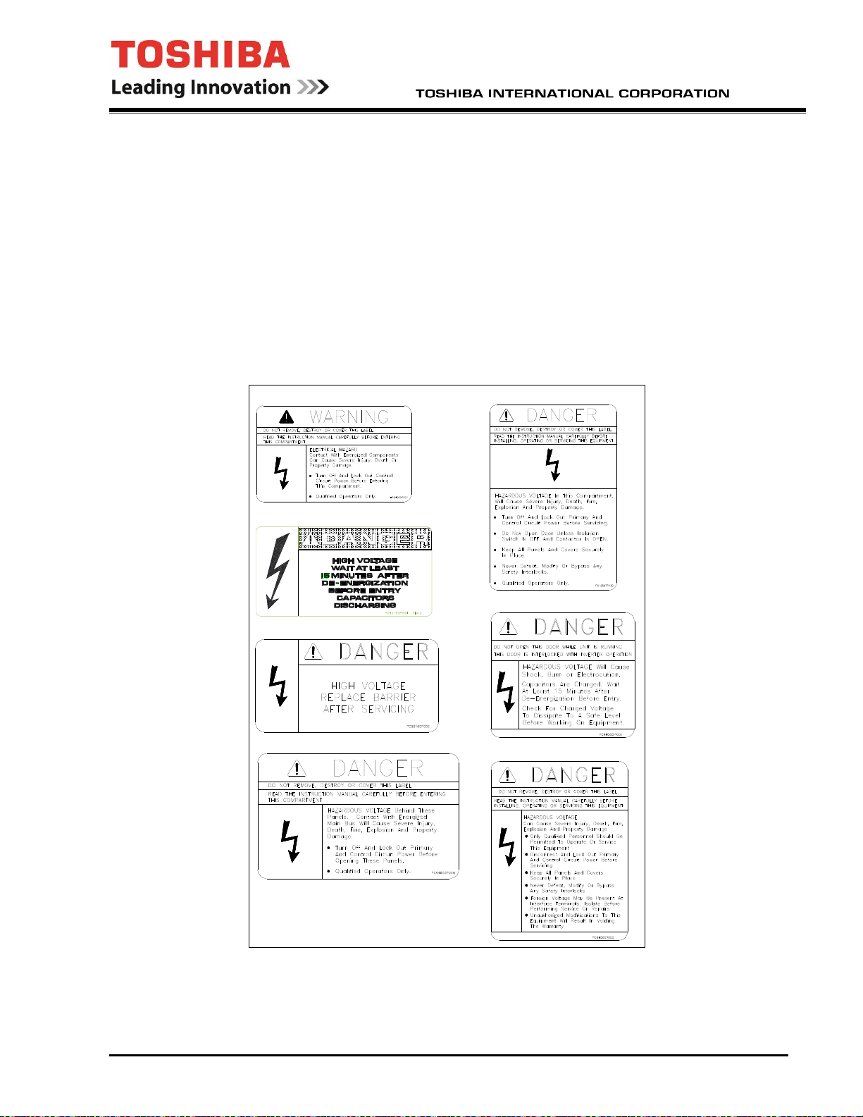
Shown below are examples of safety labels that may be found attached to the equipment. DO NOT
remove or cover any of the labels. If the labels are damaged or if additional labels are required, contact your
Toshiba representative for additional labels.
Labels attached to the equipment are there to provide useful information or to indicate an
imminently hazardous situation that may result in serious injury, severe property and equipment damage, or
death if the instructions are not followed.
SAFETY labels that will be found on the equipment are shown below:
IF08CZ10 April, 2019 - vii -

Additional SAFETY labels that will be found on the equipment or in the manual that has the
CE mark applied are shown below:
Electrical hazard.
Electrical hazard with the system
rated voltage listed below.
xxxxx V
Burn hazard from high surface
temperatures.
Read the manual.
Some additional SAFETY labels that may be found on the equipment are shown below:
xxx MIN
Electrical hazard with a minimum
discharge time listed below.
Do not remove covers or panels
when energized.
Use and follow lock out tag out
proceedures
This Equipment Does Not Provide Isolation
Separate Isolation Means Required
HAZARDOUS VOLTAGE Behind This Panel.
Contact With Energized Parts Will Cause
Severe Injury, Death, Fire, Explosion And
Property Damage
See The Input Section Data Label And
Drawing Number I508KW03 For Specific
Requirements
IF08CZ10 April, 2019 - viii -
MULTIPLE SOURCES OF
ELECTRICAL SUPPLY PRESENT.
DE-ENERGIZE ALL ELECTRICAL SUPPLIES
BEFORE SERVICING
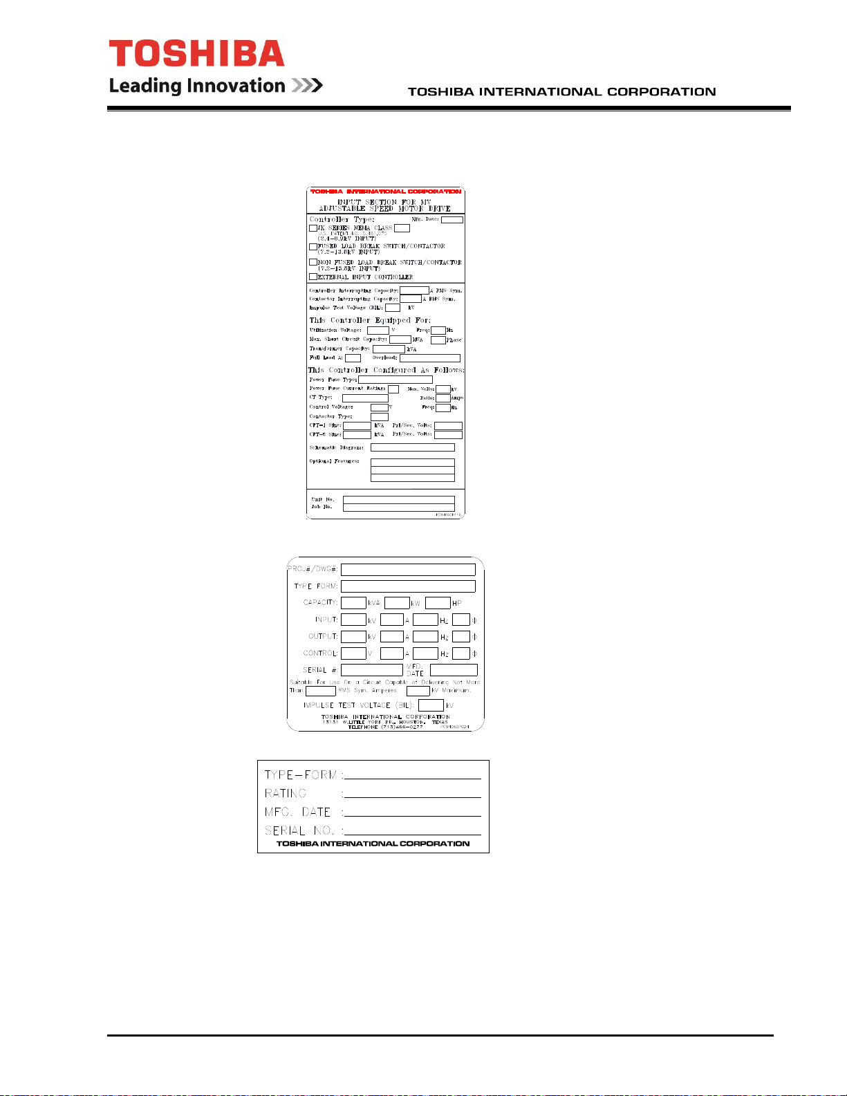
RATING labels that will be found on the equipment are shown below:
Input Controller Rating Label
Note: If no input controller is
supplied, this label will indicate the
required fuses and the minimum
acceptable ratings for the external
controller.
Adjustable Speed Drive Rating Label
Inverter Power Module Rating Label
Note:
The above labels are shown blank. The labels affixed to the equipment will be filled in with rating data
specific to the actual unit(s) furnished. Complete rating data is also provided on the rating sheet included
in the supplementary drawing packet. Ensure that all rating data matches the power system and the
driven load connected to the equipment.
IF08CZ10 April, 2019 - ix -
p
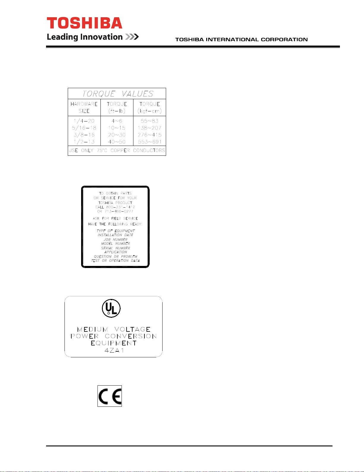
INFORMATION labels that will be found on the equipment are shown below:
Torque Label
LISTED
Service Label
USC
UL Label
(for UL Listed drives)
CE Label
(for drives designed
for use in the
ean Union)
Euro
IF08CZ10 April, 2019 - x -

Qualified Personnel
Installation, operation, and maintenance shall be performed by Qualified Personnel Only. A
Qualified Person is one that has the skills and knowledge relating to the construction, installation,
operation, and maintenance of the electrical equipment and has received safety training on the hazards
involved. In the U.S., refer to the latest edition of NFPA 70E for additional safety requirements. Outside the
U.S., follow all applicable national and local safety practices.
Qualified Personnel shall:
• Have read the entire operation manual.
• Be familiar with the construction and function of the ASD, the equipment being driven, and the
hazards involved.
• Able to recognize and properly address hazards associated with the application of motor-driven
equipment.
• Be trained and authorized to safely energize, de-energize, ground, lockout/tagout circuits and
equipment, and clear faults in accordance with established safety practices.
• Be trained in the proper care and use of protective equipment such as safety shoes, rubber
gloves, hard hats, safety glasses, face shields, flash clothing, etc., in accordance with established
safety practices.
• Be trained in rendering first aid.
For further information on workplace safety in the U.S. visit www.osha.gov. Outside the U.S.,
refer to your existing plant safety regulations.
Equipment Inspection
• Upon receipt of the equipment inspect the packaging and equipment for shipping damage.
• Carefully unpack the equipment and check for parts that were damaged from shipping, missing
parts, or concealed damage. If any discrepancies are discovered, it should be noted with the carrier
prior to accepting the shipment, if possible. File a claim with the carrier if necessary and
immediately notify your Toshiba representative.
• DO NOT install or energize equipment that has been damaged. Damaged equipment may fail
during operation resulting in further equipment damage or personal injury.
• Check to see that the rated capacity and the model number specified on the nameplate conform
to the order specifications.
• Modification of this equipment is dangerous and must not be performed except by factory trained
representatives. When modifications are required contact your Toshiba representative.
• Inspections may be required before and after moving installed equipment.
• Keep the equipment in an upright position as indicated on the shipping carton.
• Contact your Toshiba representative for assistance if required.
IF08CZ10 April, 2019 - xi -

Handling and Storage
• Use proper lifting techniques when moving the ASD; including properly sizing up the load, getting
assistance, and using a forklift if required.
• Store in a well-ventilated covered location and preferably in the original carton if the equipment
will not be used upon receipt.
• Store in a cool, clean, and dry location. Avoid storage locations with extreme temperatures, rapid
temperature changes, high humidity, moisture, dust, corrosive gases, or metal or conductive
particles.
• Do not store the unit in places that are exposed to outside weather conditions (i.e., wind, rain,
snow, etc.).
• Store in an upright position as indicated on the shipping carton.
• Include any other product-specific requirements.
Disposal
Never dispose of electrical components via incineration. Contact your state environmental agency
for details on disposal of electrical components and packaging in your area.
IF08CZ10 April, 2019 - xii -

Installation Precautions
Location and Ambient Requirements
• Adequate personnel working space and adequate illumination must be provided for adjustment,
inspection, and maintenance of the equipment. In the U.S., refer to NEC Article 110-34 for
requirements. Outside the U.S., follow applicable local electrical code requirements.
• Avoid installation in areas where vibration, heat, humidity, dust, fibers, metal or conductive
particles, explosive/ corrosive mists or gases, or sources of electrical noise are present.
• Do not install the ASD where it may be exposed to flammable chemicals or gasses, water,
solvents, or other fluids.
• The installation location shall not be exposed to direct sun light .
• MTX drives are designed for outdoor use with exposure to rain and direct sunlight.
• Allow proper clearance spaces for installation. Do not obstruct the ventilation openings. Refer to
the recommended minimum installation dimensions as shown on the enclosure outline drawings.
• The ambient operating temperature shall be between 0 and 40
otherwise.
Mounting Requirements
o
C (32 and 105 oF), unless stated
• Only Qualified Personnel should install this equipment.
• Install the unit in a secure upright position in a well-ventilated area.
• A noncombustible insulating floor or mat should be provided in the area immediately surrounding
the electrical system at the place where maintenance operations are to be performed.
• Equipment should be installed according to all applicable national, regional, and industry codes
and standards. In the U.S., installation of the equipment should conform to NEC Article 110
Requirements For Electrical Installations and to OSHA requirements.
• In the U.S., installation practices should conform to the latest revision of NFPA 70E Electrical
Safety Requirements for Employee Workplaces. Outside the U.S., applicable national and local
installation safety practices should be followed. In the EU refer to section 6.5 of HD 637 and its sub
clauses.
IF08CZ10 April, 2019 - xiii -
Conductor Routing and Grounding
• Use separate metal conduits for routing the input power, output power, and control circuits.
• A separate ground cable should be run inside the conduit with the input power, output power, and
control circuits.
• DO NOT connect control terminal strip return marked LG to earth ground.
• Always ground the unit to prevent electrical shock and to help reduce electrical noise.
• It is the responsibility of the person installing the ASD or the electrical maintenance personnel to
provide proper grounding and branch circuit protection in accordance with all applicable national
and local electrical codes (in the U.S. refer to the current version of NEC).
The Metal Of Conduit Is Not An Acceptable Ground.
Connections
WARNING
WARNING
Contact With Energized Wiring Will Cause Severe Injury Or Death.
• Turn off, lockout, and tagout all power sources before proceeding to connect the power wiring to
the equipment.
• After ensuring that all power sources are turned off and isolated in accordance with established
lockout/tagout procedures, connect three-phase power source wiring of the correct voltage to the
correct input terminals and connect the output terminals to a motor of the correct voltage and type
for the application. In the U.S., refer to NEC Article 300 – Wiring Methods and Article 310 –
Conductors For General Wiring and size the branch circuit conductors in accordance with NEC
Table 310.16. Outside the U.S., follow your national and local electrical codes.
• If multiple conductors that are smaller than the recommended sizes are used in parallel for the
input or output power, each branch of the parallel set shall have its own conduit and not share its
conduit with other parallel sets (i.e., place U1, V1, and W1 in one conduit and U2, V2, and W2 in
another) (refer to NEC Article 300.20 and Article 310.4 for U.S. requirements). National and local
electrical codes should be referenced if three or more power conductors are run in the same conduit
(in the U.S. refer to 2002 NEC Article 310 adjustment factors on page 70-142). Outside the U.S.,
consult your national and local electrical codes for additional requirements for running multiple
conductors.
• Ensure that the 3 phase input power is Not connected to the output of the ASD. This will damage
the ASD and may cause injury to personnel.
• Do not install the ASD if it is damaged or if it is missing any component(s).
• Turn the power on only after attaching and/or securing the front cover.
• Ensure the correct phase sequence and the desired direction of motor rotation in the Bypass
mode (if applicable).
IF08CZ10 April, 2019 - xiv -

Protection
• Ensure that primary protection exists for the input wiring to the equipment. This protection must be
able to interrupt the available fault current from the power line. The equipment may or may not be
equipped with an input disconnect (option).
When sizing and installing the upstream cabling and protection equipment:
- Consult the Manufacturer’s Nameplate for Equipment Voltage and Current
- The equipment must be installed to meet the National Electrical Code rules of the
- The equipment must bear a safety mark accepted by the country where installed.
- The equipment must be installed by a qualified electrician.
• All cable entry openings must be sealed to reduce the risk of entry, by vermin, and to allow for
maximum cooling efficiency.
• Follow all warnings and precautions, and do not exceed equipment ratings.
• If using multiple motors, provide separate overload protection, for each motor, and use V/f control.
• External dynamic braking resistors, if supplied, must be thermally protected.
Requirements.
country where installed as a branch circuit protector.
• It is the responsibility of the person installing the ASD or the electrical maintenance personnel to
setup the Emergency Off braking system of the ASD. The function of the Emergency Off braking
function is to remove output power, from the drive, in the event of an emergency. A supplemental
braking system may also be engaged in the event of an emergency.
Note: A supplemental emergency stopping system should be used with the ASD.
Emergency stopping should not be a task of the ASD alone.
System Integration Precautions
The following precautions are provided as general guidelines for the setup of the ASD within the
system.
• The Toshiba ASD is a general-purpose product. It is a system component only and the system
design should take this into consideration. Please contact Toshiba for application-specific
information and for training support.
• The Toshiba ASD is part of a larger system and the safe operation of the device will depend on
observing certain precautions and performing proper system integration.
• A detailed system analysis and job safety analysis should be performed by the systems designer
and/or systems integrator, before the installation of the ASD component. Contact Toshiba for
options availability and for application-specific system integration information, if required.
IF08CZ10 April, 2019 - xv -

Personnel Protection
• Installation, operation, and maintenance shall be performed by Qualified Personnel Only.
• A thorough understanding of the ASD will be required before the installation, operation, or
maintenance of the ASD.
• Rotating machinery and live conductors can be hazardous and shall not come into contact with
humans. Personnel should be protected from all rotating machinery and electrical hazards at all
times.
• Insulators, machine guards, and electrical safeguards may fail or be defeated by the purposeful or
inadvertent actions of workers. Insulators, machine guards, and electrical safeguards are to be
inspected (and tested where possible) at installation and periodically after installation for potential
hazardous conditions.
• Do not allow personnel near rotating machinery. Warning signs to this effect shall be posted at or
near the machinery.
WARNING
• Do not allow personnel near electrical conductors. Human contact with electrical conductors can
be fatal. Warning signs to this effect shall be posted at or near the hazard.
• Personal protection equipment shall be provided and used to protect employees from any hazards
inherent to system operation.
IF08CZ10 April, 2019 - xvi -

System Setup Requirements
• When using the ASD as an integral part of a larger system, it is the responsibility of the ASD
installer or maintenance personnel to ensure that there is a fail-safe in place, i.e., an arrangement
designed to switch the system to a safe condition if there is a fault or failure.
• System safety features should be employed and designed into the integrated system in a manner
such that system operation, even in the event of system failure, will not cause harm or result in
personnel injury or system damage (i.e., E-Off, Auto-Restart settings, System Interlocks, etc.).
• The programming setup and system configuration of the ASD may allow it to start the motor
unexpectedly. A familiarity with the Auto-restart settings is a requirement to use this product.
• Improperly designed or improperly installed system interlocks may render the motor unable to
start or stop on command.
• The failure of external or ancillary components may cause intermittent system operation, i.e.; the
system may start the motor without warning.
• There may be thermal or physical properties, or ancillary devices integrated into the overall
system that may allow for the ASD to start the motor without warning. Signs at the equipment
installation must be posted to this effect.
• If a secondary magnetic contactor (MC) is used between the ASD and the load, it should be
interlocked to halt the ASD before the secondary contact opens. If the output contactor is used for
bypass operation, it must be interlocked such that commercial power is never applied to the ASD
output terminals (U, V, and W).
• Power factor improvement capacitors or surge absorbers must not be installed on the output of
the ASD.
• Use of the built-in system protective features is highly recommended (i.e., E-Off, Overload
Protection, etc.).
• The operating controls and system status indicators should be clearly readable and positioned
where the operator can see them without obstruction.
• Additional warnings and notifications shall be posted at the equipment installation location as
deemed required by Qualified Personnel.
IF08CZ10 April, 2019 - xvii -

Operational and Maintenance Precautions
• Turn off, lockout, and tagout the main power, the control power, and instrumentation connections
before inspecting or servicing the drive, or opening the door of the enclosure.
• Turn off, lockout, and tagout the main power, the control power, and instrumentation connections
before proceeding to disconnect or connect the power wiring to the equipment.
• The capacitors of the ASD maintain a residual charge for a period of time after turning the ASD
off. The required time for each ASD typeform is indicated with a cabinet label and a Charge LED.
Wait for at least the minimum time indicated on the label and ensure that the Charge LED has gone
out before opening the door of the ASD once the ASD power has been turned off.
• Do Not attempt to disassemble, modify, or repair the ASD. Call your Toshiba sales representative
for repair information.
• Do not place any objects inside of the ASD.
• Turn the power on only after attaching (or closing) the front cover and Do Not remove the front
cover of the ASD when the power is on.
• If the ASD should emit smoke or an unusual odor or sound, turn the power off immediately.
• The heat sinks, magnetics, and other components may become extremely hot to the touch. Allow
the unit to cool before coming in contact with these items.
• Remove power from the ASD during extended periods of non-use.
• The system should be inspected periodically for damaged or improperly functioning parts,
cleanliness, and to ensure that the connectors are tightened securely.
WARNING
• Ensure that the Run functions (F, R, Preset Speed, etc.) of the ASD are off before performing a
Reset. The post-reset settings may allow the ASD to start unexpectedly.
• In the event of a power failure, the motor may restart after power is restored.
• Retry or Reset settings may allow the motor to start unexpectedly. Warnings to this effect should
be clearly posted near the ASD and motor.
DO NOT install, operate, perform maintenance, or dispose of this equipment until you have read
and understood all of the product warnings and user directions. Failure to do so may result in
equipment damage, operator injury, or loss of life.
IF08CZ10 April, 2019 - xviii -

This page intentionally left blank.
IF08CZ10 April, 2019 - xix -

CONTENTS
INTRODUCTION ............................................................................................................. 1
INITIAL COMMISSIONING ............................................................................................. 2
Confirmation of Wiring ................................................................................................. 2
Start-Up and Test ........................................................................................................ 2
Cautions on Changing Setting Parameters ................................................................. 3
INSPECTIONS AND MAINTENANCE ............................................................................ 4
Daily Inspections ......................................................................................................... 4
Regular Inspections ..................................................................................................... 4
Main Components ....................................................................................................... 5
Cautions on Handling Printed Wiring Boards .................................................................. 5
Recommended Parts to be Regularly Renewed .......................................................... 6
Recommended Spare Parts ........................................................................................ 7
Preparations for Inspection and Maintenance of Equipment (Powering-Off) ............... 8
Recovery after Inspection and Maintenance of Equipment (Powering-On) ................. 9
OVERVIEW ................................................................................................................... 10
Display/Keypad (EOI) ................................................................................................ 10
EOI Diagram ........................................................................................................ 10
How to Handle Faults ................................................................................................ 12
Description of Terminology ........................................................................................ 12
General Specifications (Structure) ............................................................................. 13
Altitude and Temperature De-rating .......................................................................... 14
Motor Cable Length ................................................................................................... 14
General Specifications (Electrical) ............................................................................. 15
General Specifications (Control) ................................................................................ 16
Rating Specifications ................................................................................................. 18
Protective Functions .................................................................................................. 22
General Cubicle Structure ......................................................................................... 24
Cubicle Structure and Dimensions ............................................................................ 24
Dimensions and Weights of Equipment ........................................................................ 25
INTERFACE .................................................................................................................. 28
Power Supply Interface and Ground .......................................................................... 28
Grounding ..................................................................................................................... 28
Motor Interface .......................................................................................................... 29
Speed Sensor Interface (Option) ............................................................................... 29
Resolver .................................................................................................................... 29
PG (Pulse Generator) ................................................................................................ 29
Pulse Signal Output ................................................................................................... 30
Digital Output ............................................................................................................. 35
Analog Input .............................................................................................................. 35
Analog Output ........................................................................................................... 37
General-purpose Analog Output ................................................................................ 37
Additional Analog Outputs ......................................................................................... 37
CIRCUIT OPERATION ................................................................................................. 38
Main Circuit Configuration ......................................................................................... 38
Control ....................................................................................................................... 42
Vector Control Block Diagram ................................................................................... 42
IF08CZ10 April, 2019 - xx -

V/f Control Block Diagram ......................................................................................... 42
Speed Reference....................................................................................................... 43
Vector Control Speed Control .................................................................................... 44
Vector Control Simulator Follower Control (SFC, optional control used with a speed
sensor) ...................................................................................................................... 45
Vector Control Torque Reference and Current Reference ........................................ 45
Vector Control IQ Limit (Torque current limit) ............................................................ 46
Vector Control D-Q Axis Current Control ................................................................... 47
V/f Control ................................................................................................................. 48
Control Circuit for SM (Synchronous Motor) control .................................................. 49
SM Control Block Diagram ........................................................................................ 50
Speed Feedback (Option) ......................................................................................... 51
Resolver .................................................................................................................... 51
PG ............................................................................................................................. 51
OPERATION ................................................................................................................. 52
Pre-Operation Check Points ...................................................................................... 53
Powering-On ............................................................................................................. 53
Operation ................................................................................................................... 53
Normal Operation ...................................................................................................... 53
Powering-Off ............................................................................................................. 53
DATA CONTROL .......................................................................................................... 54
Setting Data ............................................................................................................... 54
FAULT AND RECOVERY ............................................................................................. 54
Cautions when Handling Fault ................................................................................... 54
Repair ........................................................................................................................ 55
Cautions on Repair .................................................................................................... 55
DRIVE INSTALLATION DRAWINGS ............................................................................ 56
Frame 0 drive lifting and assembly ............................................................................ 56
Frame 0 4160V module lifting and installation ........................................................... 57
Frame 0 2400V module lifting and installation ........................................................... 57
Frame 1 4160V drive lifting and assembly ................................................................. 58
Frame 1 drive lifting and assembly (cont’d) ............................................................... 59
Frame 1 2400V module lifting and installation ........................................................... 60
Frame 1 4160V module lifting and installation ........................................................... 60
Frame 2 drive lifting and assembly ............................................................................ 61
Frame 2 drive main cable installation ........................................................................ 62
Frame 2 module lifting ............................................................................................... 63
Frame 2 4160V module installation ........................................................................... 64
Frame 3 drive lifting and assembly ............................................................................ 65
Frame 3 drive main cable installation ........................................................................ 66
Frame 3 2400V module installation ........................................................................... 68
Frame 3 4160V module installation ........................................................................... 69
Frame 4 drive lifting and assembly ............................................................................ 70
Frame 4 drive main cable installation ........................................................................ 71
Frame 4 module lifting ............................................................................................... 72
Frame 4 2400V module installation ........................................................................... 73
Frame 4 4160V module installation ........................................................................... 74
IF08CZ10 April, 2019 - xxi -

Frame G4P drive main cable installation ................................................................... 76
Frame G4P module lifting and installation ................................................................. 77
Frame G4P module lifting and installation continued ................................................. 78
Frame H4P drive lifting and assembly ....................................................................... 79
Frame H4P drive main cable installation ................................................................... 80
Frame H4P module lifting and installation ................................................................. 81
Frame H4P module lifting and installation continued ................................................. 82
Frame A2 module lifting and installation .................................................................... 83
Frame A2 drive lifting and assembly .......................................................................... 84
Frame B2 2400V module lifting and installation Type 1 ............................................. 85
Frame B2 module lifting and installation Type 2 ........................................................ 86
Frame B2 drive lifting and assembly .......................................................................... 87
Frame D2 module lifting and assembly ..................................................................... 88
Frame D2 drive lifting and assembly ......................................................................... 89
Frame D2 drive main terminal locations .................................................................... 90
Frame A4µ module lifting and installation .................................................................. 91
Frame A4µ drive lifting and assembly ....................................................................... 92
Frame A4 module lifting and installation .................................................................... 93
Frame A4 drive lifting and assembly .......................................................................... 94
Frame B4 module lifting and installation .................................................................... 95
Frame B4 drive lifting and installation ........................................................................ 96
Frame B6S module lifting and installation ................................................................. 97
Frame B6S drive lifting and assembly ....................................................................... 98
Frame B6S drive main terminal locations .................................................................. 99
Frame C6S module lifting and installation ............................................................... 100
Frame C6S drive lifting and assembly ..................................................................... 101
Frame C6S drive main terminal locations ................................................................ 102
Frame D6S module lifting and installation ............................................................... 103
Frame D6S drive lifting and assembly ..................................................................... 104
Frame D6S drive main terminal locations ................................................................ 105
Frame F6S & F6S+ module lifting and installation ................................................... 106
Frame F6S drive lifting and assembly ..................................................................... 107
Frame F6S+ drive lifting and assembly ................................................................... 108
Frame F6S & F6S+ drive main terminal locations ................................................... 109
Frame MTX-15 drive lifting and assembly ............................................................... 110
Frame MTX-30 drive lifting and assembly ............................................................... 111
Frame MTX2-15 module lifting and installation ....................................................... 112
Frame MTX2-15 drive lifting and assembly ............................................................. 113
Frame A4R module lifting and installation ............................................................... 114
Frame A4R drive lifting and assembly ..................................................................... 115
Frame B4R module lifting and installation ............................................................... 116
Frame B4R drive lifting and assembly ..................................................................... 117
IF08CZ10 April, 2019 - xxii -

INTRODUCTION
Thank you for purchasing the T300MV2, MTX, or MTX2 Medium Voltage ASD. This adjustable
frequency, solid-state AC drive features a 3φ input isolation transformer with a 24/36-pulse converter design,
a 32-bit CPU, and a three-unit power module inverter section providing a 7 level output for 6600V drives, a 5
level output for 4160/3300V drives and 3 level output for 2400V drives. These drives also feature as
standard, an 8 key Control Panel with a LCD screen and 2 discrete LED lamps to indicate Ready, Run,
Local, Remote and Alarm/Fault.
On most power systems, this drive will meet IEEE-519-1992 harmonic regulation guidelines without
installing additional harmonic filters. The input power factor is typically 0.95. The multi-level output
produces a more sinusoidal voltage and reduces stress on the motor winding insulation. This drive uses
high capacity 3300V IGBTs to improve reliability, reduce switching losses, and improve control performance.
The PP7 control processor and 6-layer control board achieves high integration and reliability.
IF08CZ10 April, 2019 - 1 -
INITIAL COMMISSIONING
The drive should be commissioned by qualified personnel only. Below are some general steps
required for commissioning.
CAUTION
Confirmation of Wiring
Make the following final checks before applying power to the unit:
1) Confirm that source power is connected to terminals L1, L2, L3 (R, S, T). Connection of
incoming source power to any other terminals will damage the drive. Other control voltages
may be required. Consult your custom equipment diagrams shipped with the drive for any
other requirements.
2) Verify that the power modules are properly installed and that there was no damage during
shipping or handling.
3) Verify that there are no loose connections or wires and that all of the required shipping split
connections have been made.
4) Verify all external control circuit wiring is complete and properly connected.
5) The 3-phase source power should be within the correct voltage and frequency tolerances.
6) The motor leads must be connected to terminals T1, T2, T3 (U, V, W).
7) Make sure there are no short circuits or inadvertent grounds and tighten any loose connector
terminal screws.
CAUTION
Start-Up and Test
Prior to releasing the drive system for regular operation after installation, the system must
be adjusted and tested by qualified personnel. This assures correct operation, of the equipment, for
reasons with reliability and safety performance. It is important to make arrangements for such a check and
that sufficient time is allowed for it.
IF08CZ10 April, 2019 - 2 -
CAUTION

Cautions on Changing Setting Parameters
The setting data of the drive is saved in an EEPROM, non-volatile memory. When the micro
controller initializes at power-up, it reads the EEPROM data and copies it to the RAM (Random Access
Memory). From then on, the micro controller controls the drive using the values in the RAM.
When the setting parameters are changed, by the display-keypad or personal computer ("support
tool"), only the execution parameters in RAM are changed. If they need to be stored, they must be manually
written to the EEPROM. Without this operation, the next initialization or power up will cause them to be
replaced by the old data.
When a write to the EEPROM is performed, write processing may take 30 seconds. Turning off the
control power supply during write processing will make both the RAM and EEPROM data abnormal. When
the power is turned on again, this abnormal data will result in an error ("CHECK ERROR") preventing the
drive from running. If such an error occurs, the settings must be reloaded from a saved file. If no setting file
exists, the drive must be re-commissioned.
CAUTION
Do not turn off the control power supply, under any circumstances,
while writing data to the EEPROM.
IF08CZ10 April, 2019 - 3 -
INSPECTIONS AND MAINTENANCE
Maintenance and inspection is a particularly effective means to help prevent failures and reduce
down time. Creating equipment specific inspection and maintenance check sheets can help in performing
maintenance and inspection effectively. Detailed inspections and regular maintenance should be carried
out, in short cycles initially, until a schedule, reflecting the site-specific conditions, can be determined.
For items that are too high to reach, use a step ladder to gain access. Do not attempt to climb on
the equipment.
CAUTION
DANGER
Daily Inspections
Daily inspections consist mainly of visual inspections on the following items. These observations
should be made with all cubicle doors closed and safety covers installed. Any abnormalities discovered
should immediately be repaired.
1) Check the temperature, the humidity, the presence of corrosive or explosive gases, and the
presence of dust in the area.
2) Check for any abnormal sound or vibration originating from the reactor, transformer, or cooling
fans.
3) Check for abnormal odors such as the smell of burning insulating materials.
Regular Inspections
Carry out regular inspections with the power off, locked out, and with confirmation that the bus
voltage is completely discharged. Use proper power lockout/tagout procedure on the disconnecting
means in accordance with applicable local electrical codes (in the U.S., see 2002 NEC Article 430-101)
before performing any drive maintenance.
The first thing to do in maintenance and inspection is cleaning. Cleaning should be carried out
according to the conditions of the equipment. Before starting cleaning, turn off the power supply and check
that the main circuit voltage is reduced to 0. Clean dust with a vacuum, dry compressed air, and clean dry
cloths. Note that excessive air pressure when blowing out equipment may damage parts and wiring. Do
not use solvents to clean the drive. Substances stuck to the circuits, which cannot be removed by
blowing, should be wiped away using a cloth. As a basic rule, cleaning should start from the upper parts
and end at the lower parts. Cleaning of the lower parts last will allow proper removal of substances that
could drop from the upper parts.
IF08CZ10 April, 2019 - 4 -
CAUTION
DANGER

INSPECTIONS AND MAINTENANCE
(cont’d)
Main Components
1) Cooling fan - Check to see if there is any abnormality with airflow, increased fan noise, etc.
2) Air filter - Visually check if the air filter is clogged. Gently tap it outside the room to remove loose
dust. To remove caked on dirt use water and a gentle detergent, rinse it with clean water and dry it.
Otherwise replace it with a new one. Cleaning with solvents is not recommended.
3) Main circuit parts and entire cubicle - Check to see if dust is stuck to the cubicle interior or if there
is any discoloration, heat generation, abnormal sound, leakage, odor or damage with the reactor,
transformer, contactors, cables and connections, fuses, capacitors, lightening arrestors, and
resistors. Check to see that no wires or mounted parts are broken, disconnected, loose or
damaged. High voltage standoffs, insulators, and cable can be cleaned with isopropyl alcohol.
4) Printed Wiring Boards - The boards, which are made up of ICs and electronic components, must
be protected from dust, corrosive gases and extreme temperatures. Pay attention to the installation
environment of the equipment. Regular inspections, the proper cleaning, and maintenance in an
optimal environment is essential for circuit boards. Since most of the components and parts are
small and vulnerable to external forces, when cleaning them, use a brush to carefully wipe off dust.
Inspect the boards for signs of component damage, heating, and corrosion.
Cautions on Handling Printed Wiring Boards
a) All maintenance work on the board should be carried out at least 15 minutes after all
power supplies are turned off to allow the capacitors on the boards to discharge.
b) When removing the board, disconnect all the connectors and wires and remove the
mounting screws from the upper part of the board first. At this time, be careful not to drop
the boards or screws. When setting the board down, place it on a static free surface. Be
careful not to damage any components.
c) When attaching the board, do so in the order opposite to the removing procedure. Be
sure that all of the connectors and wires are connected correctly.
d) New boards are shipped in an anti-static bag. Use this bag to store them.
Note that the anti-static coating is only on the inner side of the bag.
5) Check the protection functions for proper operation (Door switches, OH, E-stop...)
6) Check the insulation resistance of the medium voltage circuits.
CAUTION
IF08CZ10 April, 2019 - 5 -
INSPECTIONS AND MAINTENANCE
(cont’d)
CAUTION
Recommended Parts to be Regularly Renewed
To use the drive for a maximum period of time, it is necessary to regularly renew (replace)
components whose characteristics have deteriorated. The table below shows the parts used for the inverter
equipment whose regular renewal is recommended for critical applications and their recommended renewal
period. We always recommend that spares be on hand to reduce down time.
Product name Recommended
renewal period
Cooling fan
Air filter 6 months Can also be cleaned.
Aluminum Electrolytic
Capacitors
On Circuit Boards
Oil-filled capacitor
Main circuit
Control power supply 7 years
Fuse Main circuit 7 years
Control circuit 7 years
7 years Sooner if dust or dirt
7 years
20 years
Remarks
damages bearings
Contact Toshiba for
replacement of these
devices
IF08CZ10 April, 2019 - 6 -

Recommended Spare Parts
Spare parts are an important part of downtime reduction. When parts in the drive have failed, onhand spare parts are necessary to shorten the mean time to repair (MTTR). Since replacement of discrete
components is time consuming, it is recommended that entire assemblies be replaced. Recommended
spare parts common to all drives are shown in the following tables. The recommended spare rate and
minimum amount can serve as references for the minimum number of spare parts relative to the total
number of drives on site. It is recommended that the quantity be determined in accordance with the number
drives on site. Many other parts are job specific. It is up to the end user to determine what other parts may
be needed.
Recommended Common Spare Parts **
Number of
Product name Model/Rating
CTR Control board ARND-4044(*) 1 each 10% 1
GSD Gate signal distribution board PC61910P203A 1 each 10% 1
OLB Optical gate signal board ARND-8205(*) 3 each 10% 1
XIO External input/output board ARND-4045(*) 1 each 10% 1
EXIO External input/output board PC61910P205B 1 each 10% 1
IFBK Interface board PC61910P207E 1 each 10% 1
EXIF External Interface board PC61910P206A 1 each 10% 1
VDET Voltage detection board ARND-3127(*) 3 each 10% 1
IPAD Keypad interface board PC61910P204A 1 each 10% 1
DISP Display/keypad PC61910P216 1 each 10% 1
PS1 Control power supply FYX900/63T-BGEE 1 each 10% 1
GDI Earth fault detection ARND-8126A 1 each 10% 1
Control Fuses * * 2 each 10% 2
Main Fuses * * 3 each 10% 3
Pt fuses * * 4 each 10% 4
Rectifier fuses * * 36/12 10% 3
Power modules*** * * 3 10% 1
Cooling Fans * * * 10% 1
* This data is job/inverter specific. Check the drawings for the specific inverter for this information.
** This is a general list of spares. Check the specific job drawings for other components that may need to be
spared.
parts per drive
4160V/2300V
*** It is recommended that failed power modules be replaced as a unit and that the failed modules
be returned to Toshiba for repair and testing. (T300MV2 & MTX2). For Twin drives, there are 6
modules. For 6600V drives there 3x2400V modules and 3x4160V modules. MTX drives
require field repair of the module by factory trained personnel.
Recommended spare parts
Spare
rate
Recommended
Min Q’ty
IF08CZ10 April, 2019 - 7 -
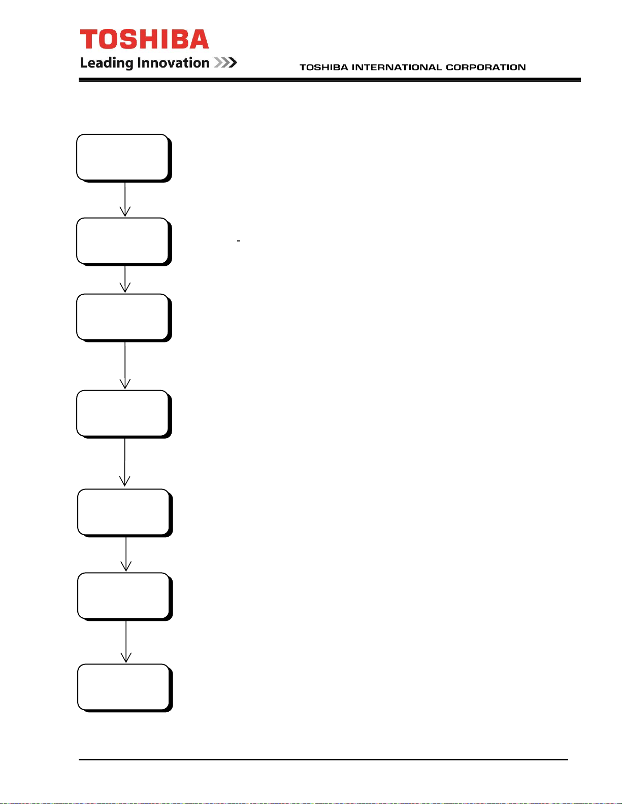
Preparations for Inspection and Maintenance of Equipment (Powering-Off)
Stop the
equipment
Main power
OFF
Control power
OFF
Wait for DC bus
discharge
Voltage check
Grounding
Work
1) Stop the equipment and check that the motor has
completely stopped.
2) Press the interlock switch on the operation panel (See Fig. 1 in the next section).
The light on the switch should turn on.
3) Turn off the external main power supply. Disconnect and lockout the main
power.
4) Turn off and lock out the control power supply.
5) Turn off and lock out any other job specific power feeding the drive.
6) Wait for 15 minutes or more for the bus to discharge.
7) Verify that all power is removed by measuring the main, the DC bus, the control,
and any other external source voltage levels with properly rated measuring
equipment.
Note! A meter rated for the main circuit voltage is required to safely check the
main circuit voltages.
8) Ground the 3-phase input power supply terminal at the main circuit input
terminals.
9) Perform the necessary maintenance.
IF08CZ10 April, 2019 - 8 -

gr
Recovery after Inspection and Maintenance of Equipment (Powering-On)
Check for tools.
Remove added
ounding.
Close the door
Control power
supply ON
Main power
supply ON
Prepare
operation of
equipment
1) Check the drive to make sure no tools or other foreign objects were left in the
drive.
2) Remove any grounding devices that may have been attached to the main
circuit input terminal.
3) Replace any safety barriers or covers that were removed for maintenance. Close
and latch all doors. Operation of the equipment cannot start when the door of the
main circuit related cubicles is open.
4) Turn on the control power supply.
5) Turn on any other external power suppy sources.
6)Turn on the external main power supply.
7) After safety checks, prepare for the operation.
Press the interlock switch on the operation panel (See Fig. 1 in the next section).
(When the LED is turned off, the interlock is off. If the drive is ready, it
will start if commanded).)
IF08CZ10 April, 2019 - 9 -

OVERVIEW
Display/Keypad (EOI)
The following figure shows the display/keypad of the equipment. Refer to the keypad operation
manual for more details on its use.
EOI Diagram
11 12 13
Figure 1.
1
5
6
2
7
3
8
4
9
10
IF08CZ10 April, 2019 - 10 -

1. 4 Digit 7 Segment Display – Brightly displays the frequency when connected to V/Hz, Vector and SM
drive types. Displays feedback (%) when connected to a Static Var. Controller.
2. Graphical LCD – Displays user information in text and numerical form.
3. Green Local/Remote LED – The green LED is lit when in local mode and off during remote mode.
4. Green and Red Status LED’s:
• Not ready and not running – Both Red and Green off.
• Ready and not running – Green LED only
• Ready and running – Red LED only.
• Fault – Fast blinking Red LED. (0.5Hz).
• Alarm – Slow blinking red if running or green if not running. (1.5Hz).
• Test mode – Alternating red and green regardless of condition. (0.5Hz).
5. Encoder – This is a multi-function device. If pushed, it will function as an Enter/select button*. If turned
clockwise, it will scroll down a menu listing and increments a selected field’s parameter data. If turned
counter clockwise, it will scroll up a menu listing and decrement a selected field’s parameter data.
(*Enter action – Selects a menu item to be changed or accepts and writes the changed data of a
selected field. This key, when in the Main tab and held for more than 2 seconds will toggle the direction
of the motor. This function only works if the drive is not running.)
6. Local/Remote key – Toggles between Local and Remote mode’s while in the Main screen and the drive
is not running. To toggle modes the key must be held for at least 2 seconds.
7. Escape key – Multi function key. It returns to the previous level of the menu tree. It cycles through the
tabs (see figure 2).
8. Run key – Will run the drive when in local mode. (Note: If the drive does not have a reference speed it
will display forward direction even though it may be in reverse direction. When a reference speed is
given it will display the correct direction.)
9. Mode key – This key will cycle through the tabs (see figure 2). This key will also initialize the selection of
individual digits by position in conjunction with the encoder when changing the values of parameters.
10. Stop key – This key will stop the drive from running when in local mode and works from all screens.
(Please refer to Section 4.1 to change the effect of the STOP key when in Local or Remote Mode.)
11. Commissioning Tool Port – Ethernet port used for communication to the commissioning and support tool.
A cross over cable may be required to establish a direct connection to a PC.
12. RESET Pushbutton – This pushbutton is used to clear inverter faults and alarms displayed on the LCD.
13. INTERLOCK Pushbutton – This pushbutton is used to disable the inverter via a hard-wired circuit. The
pushbutton is illuminated while the inverter is interlocked, and extinguished for normal operation.
Operating the INTERLOCK pushbutton will result in an inverter gate block and free-run deceleration of
the load.
IF08CZ10 April, 2019 - 11 -

How to Handle Faults
In the event of a fault, the following measures should be taken:
(1) Record the fault message shown on the display on the operation panel.
(2) Collect the trace back data, if the commissioning software package was purchased.
(3) See the Fault and Recovery section.
Description of Terminology
This section describes the special terms used in this manual.
Description of Terminology
Term Meaning
Power
module
IGD board
OLB board
VDET board
GSD board Gate Signal Distributor. Board that distributes gate signals to each output phase.
CTR board Inverter main control board
TEX board
EEPROM Electrical Erasable Programmable Read Only Memory
IGBT Insulated Gate Bipolar Transistor
LCD Liquid Crystal Display
LED Light Emitting Diode
MCCB Molded Case Circuit Breaker
PP7
PSM
RAM Random Access Memory
Initialize
Interface Means by which this equipment transfers signals to/from external devices.
Inverter
Overload Operation at a current output that exceeds the continuos rating of the equipment.
Display-
keypad
Load Refers to a motor that receives power from this equipment.
A single-phase DC-fed inverter module using IGBTs.
IGBT Gate Driver Board. Converts gate signals sent in optical signal form to
electric signals.
Optical Link Board. Converts gate signals from electric to optical signals for
isolation.
Voltage Detection Board. Board that measures analog voltage signals and
converts them to optical signals.
Twin Expansion Board. Distributes the gate signals to the power modules for
twin drives.
Power electronics Processor for Various Inverter control Integration (VII=7).
Toshiba dedicated power electronics control 32-bit micro-controller.
Switching power supply that providing ±15 VDC and +5 VDC for boards.
Act of initialization. When the control power switch is turned from OFF to ON the
inverter equipment initializes data and circuits.
Inverse converter that converts DC power to AC power.
(DC → AC conversion)
Operational panel installed on the cubicle surface that is used for data display
and basic operations.
IF08CZ10 April, 2019 - 12 -

A
3
General Specifications (Structure)
The general specifications (structure) of the equipment are shown in the following table.
General Specifications (Structure)
Item Standard specification Additional optional
specification
Applicable standard UL, NEMA
Ambient
conditions
Temperature
0 to +40°C for T300MV2
-20 to +50°C for MTX series
-45 to +50°C for MTX2 series
-20 to +60°C for storage
Humidity Max 95%, no condensation
(except MTX series when heaters are
powered)
Altitude 1000 m Max. above sea level Higher altitudes
Installation
location
Indoors
Outdoors for MTX series
Vibration 10 to 60 Hz, 0.5 G or less
Corrosive
factors
Hydrogen Sulfide (H
Sulfur Dioxide (SO2) 0.05 PPM
S) 0.001 PPM
2
Chlorine gas (Cl2) 0.1 PPM
Ammonia gas (NH3) 0.1 PPM
Nitrogen Dioxide (NO2) 0.02 PPM
Nitrogen Oxide (NOx) 0.02 PPM
Ozone (O3) 0.002 PPM
Hydrochloric acid mist (HCl1) 0.1 mg/m
Paint color Cubicle
surface
ANSI 61 Gray (T300MV2)
White (MTX series)
Cubicle structure Front maintenance (T300MV2)
MTX requires front, back, and side access
Cubicle protective
structure
NEMA 1, Forced ventilated (T300MV2)
N3R (MTX series)
With channel base
Air filter Front mounted (T300MV2)
50C operation for
T300MV2 with a
derate.
with a derate and
and special
magnetics.
This is a list of
Consult factory for
optional colors
Remarks
Low temperature
for MTX2 is with
externally
powered heaters.
t no time should
the drive be
subjected to
conditions that
would allow
condensation to
form on the
components.
corrosive agents
know to attack
the drive
components.
Other agents
may also have
adverse effects
on the drive.
IF08CZ10 April, 2019 - 13 -

Altitude and Temperature De-rating
Altitude Derate Chart
Altitude % Amp Output Derate
3,300’ 0.0%
4,000’ 2.0%
4,500’ 3.3%
5,000’ 4.7%
Temperature Derate Chart
Ambient Temperature % Amp Output Derate
40 C
45 C
50 C
0.0%
7.5%
15.0%
Motor Cable Length
Below are cable length guidelines for use with most standard industrial motors.
Suggested Maximum Output Cable Distances
AC Motor Voltage Drive Output Voltage Max lead length
without filter
2300 2400V 0-1000 ft
2300/4000 2400V 0-1000 ft
4000V or 2300/4000 4160V 0-1000 ft
6600V 6600V 0-1000 ft
CAUTION
(1) Older motors, or motors with marginal insulation systems, may require filters to help reduce the stress on
the insulation system. Consult Toshiba application engineering.
(2) Exceeding the peak voltage and allowable voltage rise time of the motor insulation system will reduce
motor life expectancy. To insure good insulation life, consult with the motor supplier to determine motor
insulation ratings and allowable maximum output lead distance. Long lead lengths between the motor and
drive may require that filters be added to the drive output.
IF08CZ10 April, 2019 - 14 -

A
A
T
Y
Y
General Specifications (Electrical)
The general (electrical) specifications of the equipment are shown in the following table.
General (Electrical) Specifications
Item Standard specification Standard
Optional
Specification
Frame Sizes 2400V 0, A2, 1, B2, 3, D2, 4 See ratings table
4160V 0, A4µ, A4, A4R, B4,
B4R, 1, 2, 3, 4, G4P,
H4P, MTX15,
MTX30, MTX2-15
6600V A6S,B6S,C6S,D6S,
F6S,F6S+
Motor driven by this equipment Squirrel-cage induction motor Synchronous
motor
Main
power
supply
Control
power
supply
Main
circuit
Others Overload capacity 100% - continuous
Input supply voltage and
range of fluctuation
Output voltage 0 ~ Rated Voltage
Supply voltage
frequency
PWM frequency 1024Hz 2400V
Regeneration system None PWM Regen is available
Ground protection Yes
Receptacle No Yes
Motor cooling fan control No
Cabinet space heater No (indoor), Yes (outdoor)
Cabinet internal light No
Typical operating sound
levels measured at a
distance of 1m x 1.5m
high
Rated Voltage ±10%
(+5%/-10% for 6.9kV)
Rated Frequency ±5%
Internally supplied 480V, 60
Hz T300MV2, MTX 30. and
MTX2.
Internally supplied 240 V, 60
Hz MTX15.
2048Hz 4160V
1024Hz 6600V
110-115% - 60 sec (Depends
upon frame size and drive
rating)
Indoor & MTX-15 <80dBA
MTX-30 & MTX2-15 <90dBA
Internally
supplied 480V,
50 Hz
T300MV2,
MTX30, &
MTX2.
Internally
supplied 240V,
50 Hz MTX15.
125%,150%,
dditional
Optional
Specification
External
supply as an
option.
175%,200%
225%,250%
es
es Space heaters
Remarks
for specific kVA
ratings available
ll MTX series
drives require
externally
supplied space
heater power.
on select frames
only
he higher OL
ratings require a
reduction in
continuous
capacity.
must be externally
powered.
IF08CZ10 April, 2019 - 15 -

General Specifications (Control)
The general (control) specifications are shown in the following table.
General Control Specifications
Item Standard specification Option Remarks
Maximum output frequency 75Hz
(66Hz for sync- transfer drives)
Speed sensor (PG pulse output) No Yes
Basic control
performance
Operation
specification
Communicati
ons
Cubicle
display/
operation
Basic control
system
Operation control
range
Field weakening
control
Speed accuracy
Speed resolution 1/25000
Acceleration/deceler
ation time
Restart after
instantaneous
interruption
Serial interface None MODBUS
Commissioning/Mai
ntenance Tool
LED 1 lamp
LED 2 lamp
LCD display 128x64 Pixel Graphical LCD display
Operation apparatus Backlit type interlock switch: 1
Connector Personal computer connection
Induction Motor Volts/Hertz Induction Motor
3%-100% 1%-100% Limited by motor
1:1.5 1:5 Vector Control
±0.5% ±0.01%
(Digital setting)
0.1 – 3276.7 sec,
acceleration/deceleration
independent setting
Possible
(more than 5 cycles interruption
causes shut down)
Ethernet (with modular jack attached
to keypad)
READY: Operation preparation
completed(Green)
RUN: Inverter in operation(Red)
ALARM/FAULT:
Alarm slow flashing/Fault fast flashing
ON - Keypad control
OFF - Other than keypad control
Unlit reset switch: 1
Operation via 8 key keypad and a
15pulse/30detent incremental
encoder
Ethernet modular jack
90Hz all non synchtransfer drives
120Hz for most
4160V drives.
Sensor Type Vector
Induction Motor
Sensorless Vector
Synchronous Motor
Analog setting
1/1000. Isolation
transducer
recommended.
Most drives cannot
Under-voltage trip
DEVICE_NET
PROFIBUS
TL-S20
READY and RUN
light colors can be
reversed by changing
an EOI parameter
90Hz max with sine
wave filter, for
H4P, G4P, 2400V
& 6600V drives.
Sensor type vector
control uses a 1x
resolver or a PG.
The maximum PG
freq. is 100kHz.
heating
regenerate.
at 75% level
Requires optional
board.
IF08CZ10 April, 2019 - 16 -

General Control Specifications Continued:
General Control Specifications
Item Standard specification Option Remarks
Analog signal output
10VDC x 2 programmable channels on EXIO brd.
10VDC x 1 Fixed on XIO brd.
10VDC x 5 programmable channels on EXIF brd.
Analog signal input
10VDC x 3 channels on EXIO brd.
10VDC x 1 channels on XIO brd.
Digital input 6 Programmable on EXIO brd.
Photo coupler 50mA 5-24Vdc
7 Fixed on EXIO brd.
Dry contact 30Vdc 250Vac
8 Fixed on EXIF brd.
Photo coupler 50mA 5-24Vdc
4 Programmable on XIO brd.
Photo coupler 50mA 5-24Vdc
2 Fixed(UVS1 & UVS2) on XIO brd.
Photo coupler 50mA 5-24Vdc
Digital output 11 Programmable on EXIO brd.
6 dry contact 30Vdc 250Vac
5 photo coupler 50mA 5-24Vdc
2 Fixed on EXIO brd.
Dry contact 30Vdc 250Vac
6 Fixed on XIO brd.
4 photo coupler 50mA 5-24Vdc
2 dry contact 30Vdc 250Vac
4 Programmable on XIO brd.
Photo coupler 50mA 5-24Vdc
Commissioning and
Parameter setting,
Maintenance Tool
Connected
measuring
equipment must
be isolated from
ground
Connected
source
equipment must
be isolated from
ground
Fixed contact is
always used for
interlocking
control function
24V contact
always used for
internal control
functions
Optional
fault data display,
etc.
Software
Package
IF08CZ10 April, 2019 - 17 -

Rating Specifications
NEMA Type 1 Standard Ratings Table (T300MV2)
Standard
Model
M40AN22030AAA0 2400 V 300 233 268 64 74 0 0~2400 V
M40AN22035AAA0 350 272 313 75 86 0
M40AN22040AAA0 400 311 357 86 99 0
M40AN22045AAA0 450 350 402 97 111 0
M40AN22050AAA0 500 389 447 107 124 0
M4AAN22030AAA0 300 233 268 64 74 A2
M4AAN22035 AAA0 350 272 313 75 86 A2
M4AAN22040 AAA0 400 311 357 86 99 A2
M4AAN22045 AAA0 450 350 402 97 111 A2
M4AAN22050 AAA0 500 389 447 107 124 A2
M41AN22060 AAA0 600 466 536 129 148 1
M41AN22070 AAA0 700 544 625 150 173 1
M41AN22080 AAA0 800 622 715 172 198 1
M41AN22090 AAA0 900 699 804 193 222 1
M41AN22100 AAA0 1000 777 893 215 247 1
M4BAN22060 AAA0 600 466 536 129 148 B2
M4BAN22070 AAA0 700 544 625 150 173 B2
M4BAN22080 AAA0 800 622 715 172 198 B2
M4BAN22090 AAA0 900 699 804 193 222 B2
M4BAN22100 AAA0 1000 777 893 215 247 B2
M43AN22125 AAA0 1250 971 1116 269 309 3
M43AN22150 AAA0 1500 1166 1340 322 371 3
M43AN22175 AAA0 1750 1360 1563 376 432 3
M43AN22200 AAA0 2000 1554 1786 430 494 3
M4DAN22125 AAA0 1250 971 1116 269 309 D2
M4DAN22150 AAA0 1500 1166 1340 322 371 D2
M4DAN22175 AAA0 1750 1360 1563 376 432 D2
M4DAN22200 AAA0 2000 1554 1786 430 494 D2
M44AN22225 AAA0 2250 1748 2010 483 556 4
M44AN22250 AAA0 2500 1943 2233 537 618 4
M44AN22300 AAA0 3000 2331 2680 645 741 4
Specifications subject to change without notice. Inverter performance data is based on a typical 4 pole motor operating
at 0.87 pf and 0.96 efficiency.
Input
Voltage
Motor
Hp
Output
kW
Output
KVA
Output Current
100%
Overload Current
110~115%-60 s. Frame
Output Voltage
& Frequency
0~75 Hz
IF08CZ10 April, 2019 - 18 -

NEMA Type 1 Standard Ratings Table (T300MV2) Continued
Standard
Model
M40AN44030 AAA0 4160 V
M40AN44035 AAA0 350 272 313 43 50 0
M40AN44040 AAA0 400 311 357 50 57 0
M40AN44045 AAA0 450 350 402 56 64 0
M40AN44050 AAA0 500 389 447 62 71 0
M40AN44060 AAA0 600 466 536 74 86 0
M4AAN44030 AAA0 300 233 268 37 43 A4µ
M4AAN44035 AAA0 350 272 313 43 50 A4µ
M4AAN44040 AAA0 400 311 357 50 57 A4µ
M4AAN44045 AAA0 450 350 402 56 64 A4µ
M4AAN44050 AAA0 500 389 447 62 71 A4µ
M4AAN44060 AAA0 600 466 536 74 86 A4µ
M40AN44070 AAA0 700 544 625 87 100 0
M40AN44080 AAA0 800 622 715 99 114 0
M40AN44090 AAA0 900 699 804 112 128 0
M40AN44100 AAA0 1000 777 893 124 136 0
M4AAN44070 AAA0 700 544 625 87 100 A4
M4AAN44080 AAA0 800 622 715 99 114 A4
M4AAN44090 AAA0 900 699 804 112 128 A4
M4AAN44100 AAA0 1000 777 893 124 136 A4
M41AN44100 AAA0 1000 777 893 124 143 1
M41AN44125 AAA0 1250 971 1116 155 178 1
M41AN44150 AAA0 1500 1166 1340 186 214 1
M41AN44175 AAA0 1750 1360 1563 217 249 1
M41AN44200 AAA0 2000 1554 1786 248 273 1
M4BAN44100 AAA0 1000 777 893 124 143 B4
M4BAN44125 AAA0 1250 971 1116 155 178 B4
M4BAN44150 AAA0 1500 1166 1340 186 214 B4
M4BAN44175 AAA0 1750 1360 1563 217 249 B4
M4BAN44200 AAA0 2000 1554 1786 248 273 B4
M42AN44225 AAA0 2250 1748 2010 279 321 2
M42AN44250 AAA0 2500 1943 2233 310 356 2
M42AN44300 AAA0 3000 2331 2680 372 409 2
M43AN44300 AAA0 3000 2331 2680 372 428 3
M43AN44350 AAA0 3500 2720 3126 434 499 3
M43AN44400 AAA0 4000 3108 3573 496 546 3
M44AN44400 AAA0 4000 3108 3573 496 570 4
M44AN44450 AAA0 4500 3497 4019 558 642 4
M44AN44500 AAA0 5000 3885 4466 620 713 4
M44AN44550 AAA0 5500 4274 4913 682 784 4
M44AN44600 AAA0 6000 4663 5359 744 818 4
M4GAN44700 AAA0 7000 5440 6252 868 998 G4P
M4GAN44800 AAA0 8000 6217 7146 992 1091 G4P
M4HAN44800 AAA0 8000 6217 7146 992 1141 H4P
M4HAN44900 AAA0 9000 6994 8039 1116 1283 H4P
M4HAN4410K AAA0 10000 7771 8932 1240 1426 H4P
Specifications subject to change without notice. Inverter performance data is based on a typical 4 pole motor operating
at 0.87 pf and 0.96 efficiency.
Input
Voltage
Motor
Output
Hp
300 233 268 37 43 0 0~4160 V
kW
Output
KVA
Output Current
100%
Overload Current
110~115%-60 s. Frame
Output Voltage
& Frequency
0~75 Hz
IF08CZ10 April, 2019 - 19 -

NEMA Type 1 Standard Ratings Table (T300MV2) Continued
Standard
Model
M4BAN66175AAA0 6600 V 1750 1360 1563 137 158 B6S 0~6600 V
M4BAN66200AAA0 2000 1554 1786 156 179 B6S
M4BAN66225AAA0 2250 1748 2010 176 202 B6S
M4BAN66250AAA0 2500 1943 2233 195 224 B6S
M4BAN66300AAA0 3000 2331 2680 234 269 B6S
M4CAN66350AAA0 3500 2720 3126 273 314 C6S
M4CAN66400AAA0 4000 3108 3573 313 360 C6S
M4DAN66450AAA0 4500 3497 4019 352 405 D6S
M4DAN66500AAA0 5000 3885 4466 391 450 D6S
M4FAN66550AAA0 5500 4274 4913 430 495 F6S
M4FAN66600AAA0 6000 4663 5359 469 539 F6S
M4FAN66700AAA0 7000 5440 6252 547 629 F6S
M4FAN66800AAA0 8000 6217 7146 625 719 F6S+
M4FAN66900AAA0 9000 6994 8039 703 808 F6S+
Specifications subject to change without notice. Inverter performance data is based on a typical 4 pole motor operating
at 0.87 pf and 0.96 efficiency.
Input
Voltage
Motor
Output
Hp
kW
Output
KVA
Output Current
100%
Overload Current
110~115%-60 s. Frame
Output Voltage
& Frequency
0~75 Hz
N3R Standard Ratings Table (MTX)
Standard
Model
MX40AN44050AAA 4160 V 500 389 447 62 71 MTX15 0~4160 V
MX40AN44100AAA 1000 777 893 124 136 MTX15
MX40AN44150AAA 1500 1166 1340 186 214 MTX15
MX42AN44200AAA 2000 1554 1786 248 273 MTX30
MX42AN44250AAA 2500 1943 2233 310 356 MTX30
MX42AN44300AAA 3000 2331 2680 372 428 MTX30
Specifications subject to change without notice. Inverter performance data is based on a typical 4 pole motor operating
at 0.87 pf and 0.96 efficiency.
Input
Voltage
Motor
Output
Hp
kW
Output
KVA
Output Current
100%
Overload Current
110~115%-60 s. Frame
Output Voltage
& Frequency
0~75 Hz
N3R Standard Ratings Table (MTX2)
Standard
Model
MX45AN44050AAA 4160 V 500 389 447 62 71 MTX2-15 0~4160 V
MX45AN44100AAA 1000 777 893 124 136 MTX2-15
MX45AN44125AAA 1250 971 1116 155 178 MTX2-15
MX45AN44150AAA 1500 1166 1340 186 214 MTX2-15
Specifications subject to change without notice. Inverter performance data is based on a typical 4 pole motor operating
at 0.87 pf and 0.96 efficiency.
Input
Voltage
Motor
Output
Hp
kW
Output
KVA
Output Current
100%
Overload Current
110~115%-60 s. Frame
Output Voltage
& Frequency
0~75 Hz
IF08CZ10 April, 2019 - 20 -

NEMA Type 1 Regen Standard Ratings Table (T300MV2)
Standard
Model
M4AAR44070 AAA0 4160 V 700 544 625 87 100 A4R 0~4160 V
M4AAR44080 AAA0 800 622 715 99 114 A4R
M4AAR44090 AAA0 900 699 804 112 128 A4R
M4AAR44100 AAA0 1000 777 893 124 136 A4R
M4BAR44100 AAA0 1000 777 893 124 143 B4R
M4BAR44125 AAA0 1250 971 1116 155 178 B4R
M4BAR44150 AAA0 1500 1166 1340 186 214 B4R
M4BAR44175 AAA0 1750 1360 1563 217 249 B4R
M4BAR44200 AAA0 2000 1554 1786 248 273 B4R
Input
Voltage
Motor
Output
Hp
kW
Output
KVA
Output Current
100%
Overload Current
110~115%-60 s. Frame
Output Voltage
& Frequency
0~75 Hz
Specifications subject to change without notice. Inverter performance data is based on a typical 4 pole motor operating
at 0.87 pf and 0.96 efficiency.
IF08CZ10 April, 2019 - 21 -

Protective Functions
The main protective functions are shown in the following table. For other faults or more details,
refer to the troubleshooting and EOI manuals.
Protective Function Table
Item
Input main switch open AC_MCCB O O
No load connected NO_LOAD O O
Output main switch closed without signal (Welded) ACSW_C O
Output main switch opened during operation ACSW_F O O
Output main switch open timer ACSW_T O O
Brake healthy B_HLTY O O
External trip from input breaker BLA O O
Electromagnetic brake energizing circuit fault BR_F O O
Equipment ventilation fan stop C_FN O O O
Equipment ventilation fan stop timer C_FN_T O O
Current limit timer CL_T O O
Current limit alarm CL_TA O O
Control power supply loss CPSF O O*
P15 or N15 volts Power Supply Fault PN15_F O O*
Control Power from UPS Loss UPS_ERR O O*
CPU error CPU_A or M O O*
GSD brd. clock fault GSD_CLK_DWN O O*
GSD brd. voltage supply/programmable device
error GSD_ERR
U or V or W phase feedback error CURU or V or W O O*
Current Unbalance Between A and B Bank CUR_DIFF
Undercurrent Alarm UL_A O O
Undercurrent Time Delayed Fault UL_T O O*
Door open DS_T O O*
Rectifier fuse fault
Ground fault alarm GR_A_ O O O
Ground fault trip GR_T_ O O
External interlock IL O O
Motor cooling fan stop timer M_FN_T O O
Motor cooling fan stop M_FN O O O O
Motor overheat M_OH O O O O
Motor overheat alarm M_OH_A O O O
Main power supply loss MPSF O O*
Motor temperature sensor error MTMP_S O O O
AC over-current
Power Module IGBT over-current
Power Module overheat OH_T_x O O*
Input Rectifier Overheat OH_REC O O*
Transformer over heat OH_TR O O*
AC Link Reactor Overheat OH_ACL_T O O*
Abbreviation
FUSE_xP
FUSE_xN
OCA, OCA_B,
OCA_CNV
OCD_xA1
OCD_xA4
OCD_xB1
OCD_xB4
Hardware
Detection
O O*
O O*
Software
Detection
O
O O*
O O*
Heavy Fault
Coast
to stop
Decel
stop
Medium
Fault
Stop
request
Light
Fault
Alarm
Start
Interlock
IF08CZ10 April, 2019 - 22 -

Item
Overload alarm OL_A,OL_A_B O O
Overload (5 minutes) OL5, OL5_B O O
Overload (20 minutes) OL20, OL20_B O O
Over speed OSS O O*
Output frequency high OSS_F0 O O*
DC bus over-voltage positive/negative
Panel safety switch P_SW O O
Emergency Stop by Keypad DSP_ESTP O O
Parameter setting error PARA_ERR O O
PLL phase error PHASE_ERR O O
PLD error PLD_ERR O O*
Pre-charge CTT trip PRE_CTT O O
Pre-charge CTT alarm PRE_CTT_F O O O
DC Bus Charging Failure REC_F O O
Rectifier failure FUSE O O*
Reverse rotation failure REV_ROT_F O O*
Rotation/start failure ROT_F O O*
Soft stall SOFT_STL O
Analog Input Fault AIN_FAULT O O* O
Speed feedback error SP_ERR O O*
Speed feedback error2 SP_ERR2 O O*
Speed reference lost SP_LOST O O O
Speed reference lost alarm SP_LST_A O O O
Motor turning start interlock SP_SIL O
Spare input 1-4 SPA1-4 O O* O O
Spare input 1-4 timer SPA1-4_T O O* O O
System configuration error SYS_ERR O O
Communication error 1-4 TL_F1-4 O O O
Main under-voltage UV_MPSF O O
AC main voltage drop UVA_SIL
DC under-voltage start interlock UV_SIL O O O
DC under-voltage trip UVD, UVD_B O O
External equipment electrical ready condition UVA_EX O O
External safety switch UVS O O
Input voltage phase loss VAC_PH_LOSS O O
Input Voltage Phase Rotation Error VAC_ROT_F O O
Converter Input Phase Lost
Output current phase loss VINV_PH_LOSS O O
Inverter output voltage PLL error VPLL_ERR_ O O
Transfer Failure XFR_FAIL O O
Transfer Incomplete Sequence XFR_INCMP O
Capture Failure CPT_FAIL O
Stator Over Voltage OV_S O O*
Field Current Limit Timer FCL_T O O*
Field Current Limit Timer Alarm FCL_TA_ O O
Exciter Failure (Exciter Detection) FL_FAULT_ O O*
Instantaneous Field Overcurrent (Exciter
Detection) FOC
Instantaneous Field Overcurrent FOC_S O O*
Exciter Stopped while Running FSTOP O O*
Field Current Lost LF O O*
Limit Fault Reset LMT_FRST O O*
Abbreviation
OV_xP
OV_xN
VCNV_PH_LOSS
_
Hardware
Detection
Software
Detection
O O*
O O
O O*
Heavy Fault
Coast
to stop
Decel
stop
Medium
Fault
Stop
request
Light
Fault
Alarm
Start
Interlock
(Note 1) Hardware Detection: Items for which all IGBTs are directly turned off by hardware. Software Detection: Items for which the
protective interlock operation is performed by detecting errors, via software.
(Note 2) "O" marks in the interlock operation fields can be selected by parameter setting.
"*" indicates that the equipment outputs the trip signal to the input main circuit breaker.
“x” indicates the phase (U,V,W).
IF08CZ10 April, 2019 - 23 -

General Cubicle Structure
The configuration and dimensions of the equipment are described below.
Cubicle Structure and Dimensions
The equipment is made up of one or more cabinets containing the transformer, incoming terminals,
converter section, and the inverter section. All components can all be accessed from the front.
This outline is for the standard Frame 1 model. For details of this and other ratings, see the outline
drawing of each product.
ADJUSTABLE SPEED
MOTOR DRIVE
LOCAL /
ESC
REMOTE
MODERUN
1
STOP
MEDIUM VOLTAGE
Dimensional Outline of 4160V- Frame 1 Cubicle (See the following page for dimensions)
General structure
1) Indoor cubicles have a structure that allows maintenance from the front. Rear maintenance
access is not required. The cubicles may be placed within 1" of the rear wall. (T300MV2) Refer to
the outline drawings for the MTX series as this varies with the frame size.
2) Provide a maintenance space of at least 72 inches (1829 mm) in front of the cubicles.
3) Provide a clearance of at least 24 inches (610 mm) above the exhaust fans. (T300MV2)
4) The following are not included in the dimensions on the next page:
a) Handle projections
b) Door mounted device projections
c) Fastener projections
IF08CZ10 April, 2019 - 24 -

Dimensions and Weights of Equipment
Dimensions of the complete drive, including the power modules
Standard Model
Number
M40AN22030-050AAA0 103.7 (2634) N/A 74 (1880) N/A * N/A 74 (1880) 43.4 (1102)
M4AAN22030-050AAA0 103.7 (2634) N/A 48 (1219) N/A * N/A 48 (1219) 48 (1219)
M41AN22060-100AAA0 103.7 (2634) N/A 74 (880) N/A 48 (1219) N/A 122 (3099) 43.4 (1102)
M4BAN22060-100AAA0 103.7 (2634) N/A 74 (1880) N/A * N/A 74 (1880) 43.4 (1102)
M43AN22125-200AAA0 103.7 (2634) N/A 90 (2286) N/A 84 (2134) N/A 174 (4420) 49.5 (1257)
M4DAN22125-200AAA0 103.7 (2634) N/A 74 (880) N/A 48 (1219) N/A 122 (3099) 49.5 (1257)
M44AN22225-300AAA0 103.7 (2634) N/A 111 (2819) N/A 111 (2819) N/A 222 (5639) 49.5 (1257)
M40AN44030-100AAA0 103.7 (2634) N/A 74 (1880) N/A * N/A 74 (1880) 43.4 (1102)
M4AAN44030-60AAA0 103.7 (2634) N/A 48 (1219) N/A * N/A 48 (1219) 48 (1219)
M4AAN44070-100AAA0 103.7 (2634) N/A 60 (1524) N/A * N/A 60 (1524) 48 (1219)
M41AN44100-200AAA0 103.7 (2634) N/A 74 (1880) N/A 48 (1219) N/A 122 (3099) 43.4 (1102)
M4BAN44100-200AAA0 103.7 (2634) N/A 90 (2286) N/A * N/A 90 (2286) 48 (1219)
M42AN44225-300AAA0 103.7 (2634) N/A 90 (2286) N/A 74 (1880) N/A 164 (4166) 49.5 (1257)
M43AN44300-400AAA0 103.7 (2634) N/A 90 (2286) N/A 84 (2134) N/A 174 (4420) 49.5 (1257)
M44AN44400-600AAA0 103.7 (2634) N/A 111 (2819) N/A 111 (2819) N/A 222 (5639) 49.5 (1257)
M4GAN44700-800AAA0 103.7 (2634) 51 (1295) 118.5 (3010) N/A 90 (2286) 48 (1219) 307.5 (7811) 60 (1524)
M4HAN44800-10KAAA0 103.7 (2634) 51 (1295) 92.5 (2350) 100 (2540) 111 (2819) 48 (1219) 402.5 (10224) 60 (1524)
M4BAN66175-300AAA0 103.7 (2634) 30 (762) 74 (1880) N/A 48 (1219) 24 (610) 176 (4470) 48 (1219)
M4CAN66350-400AAA0 103.7 (2634) 36 (914) 100 (2540) N/A 74 (1880) 24 (610) 234 (5944) 60 (1524)
M4DAN66450-500AAA0 103.7 (2634) 36 (914) 100 (2540) N/A 90 (2286) 24 (610) 265 (6731) 60 (1524)
M4FAN66550-700AAA0 103.7 (2634) 51 (1295) 118.5 (3010) N/A 111 (2819) 24 (610) 304.5 (7734) 60 (1524)
M4FAN66800-900AAA0 103.7 (2634) 51 (1295) 92.5 (2350) 100 (2540) 111 (2819) 24 (610) 378.5 (9614) 60 (1524)
MX40AN44050-150AAA 107.2 (2723) N/A 84 (2134) N/A 84 (2134) N/A 168 (4267) 63 (1600)
MX42AN44200-300AAA 107.2 (2723) N/A 104 (2642) N/A 133.5 (3391) N/A 237.5 (6033) 72 (1829)
MX45AN44050-150AAA 107.8 (2738) N/A 109.5 (2781) * N/A N/A 109.5 (2781) 77 (1956)
M4AAR44070-100 AAA0 103.7 (2634) N/A 60 (1524) N/A 36 (914) N/A 96 (2438) 48 (1219)
M4BAR44100-100 AAA0 103.7 (2634) N/A 90 (2286) N/A 50 (1270) N/A 140 (3556) 48 (1219)
H
W
Input
Sect
W
Conv
Sect 1
Dimensions – inches (mm)
W
Conv
Sect 2
W
Inv
Sect
Output
Sect
W
W
total
D
IF08CZ10 April, 2019 - 25 -

Dimensions and weights of equipment (cont’d)
Weights of the complete drive, including the power modules
Standard Model
Number
M40AN22030-050AAA0 N/A 6000 (2727) N/A * N/A
M4AAN22030-050AAA0 N/A 5500 (2500) N/A * N/A
M41AN22060-100AAA0 N/A 6500 (2949) N/A 2500 (1134) N/A
M4BAN22060-100AAA0 N/A 8600 (3909) N/A * N/A
M43AN22125-200AAA0 N/A 10500 (4763) N/A 4500 (2041) N/A
M4DAN22125-200AAA0 N/A 10000 (4545) N/A 2800 (1273) N/A
M44AN22225-300AAA0 N/A 13000 (5897) N/A 6000 (2722) N/A
M40AN44030-100AAA0 N/A 8000 (3636) N/A * N/A
M4AAN44030-60AAA0 N/A 6600 (3000) N/A * N/A
M4AAN44070-100AAA0 N/A 7600 (3447) N/A * N/A
M41AN44100-200AAA0 N/A 10500 (4763) N/A 2500 (1134) N/A
M4BAN44100-200AAA0 N/A 12500 (5681) N/A * N/A
M42AN44225-300AAA0 N/A 12800 (5818) N/A 4500 (2041) N/A
M43AN44300-400AAA0 N/A 14300 (6500) N/A 6000 (2722) N/A
M44AN44400-600AAA0 N/A 24000 (10909) N/A 6300 (2858) N/A
M4GAN44700-800AAA0 3000 (1364) 25500 (11591) N/A 8300 (3772) 3000 (1364)
M4HAN44800-10KAAA0 3100 (1409) 20500 (9318) 20500 (9318) 9600 (4364) 3500 (1591)
M4BAN66175-300AAA0 1400 (636) 12500 (5682) N/A 3900 (1773) 1000 (455)
M4CAN66350-400AAA0 1800 (818) 18000 (8182) N/A 6000 (2727) 1500 (682)
M4DAN66450-500AAA0 3000 (1364) 20000 (9090) N/A 7500 (3409) 1700 (773)
M4FAN66550-700AAA0 3000 (1364) 23000 (10545) N/A 9500 (4318) 2000 (909)
M4FAN66800-900AAA0 3000 (1364) 16000 (7273) 16000 (7273) 9500 (4318) 2000 (909)
MX40AN44050-150AAA N/A 10000 (4545) N/A 5000 (2273) N/A
MX42AN44200-300AAA N/A 18000 (8182) N/A 6500 (2955) N/A
MX45AN44050-150AAA N/A 16000 (7273) N/A * N/A
M4AAR44070-100 AAA0 N/A 7340 (3336) N/A 1900 (864) N/A
M4BAR44100-200 AAA0 N/A 12500 (5681) N/A 2700 (1227) N/A
“*” Inverter and converter sections combined into one cubicle.
“**” Maximum weight for the frame size with the standard transformer and no options. Consult the
factory for weights for non-standard inverters, as they are job specific.
Weight
Input
lbs (kg)
Weight
Conv1**
lbs (kg)
Weight
Conv2**
lbs (kg)
Weight
Inv**
lbs (kg)
Weight
Output
lbs (kg)
IF08CZ10 April, 2019 - 26 -

Dimensions and weights of equipment (cont’d)
Dimensions and weights of the inverter power modules for T300MV2 drives
Drive Model Number Module
Voltage
Class
M40AN22030-050AAA0 2400 9.6 (244) 27.0 (686) 24.2 (615) 120 (54)
M4AAN22030-050AAA0 2400 6.6 (168) 15.4 (391) 21.0 (533) 31 (14)
M41AN22060-100AAA0 2400 11.6 (295) 30.2 (767) 31.6 (803) 235 (107)
M4BAN22060-100AAA0 2400 9.9 (251) 26.8 (681) 11.1 (282) 71 (32)
M43AN22125-200AAA0 2400 24.0 (610) 38.0 (965) 35.3 (897) 512 (232)
M4DAN22125-200AAA0 2400 13.3 (338) 24.7 (627) 12.8 (325) 105 (48)
M44AN22225-300AAA0 2400 31.2 (792) 35.4 (899) 38.6 (980) 650 (295)
M40AN44030-100AAA0 4160 9.6 (244) 27.0 (686) 24.2 (615) 140 (64)
M4AAN44030-60AAA0 4160 7.1 (181) 31.8 (808) 24.1 (613) 120 (55)
M4AAN44070-100AAA0 4160 9.6 (244) 27.0 (686) 24.2 (615) 140 (64)
M41AN44100-200AAA0 4160 11.6 (295) 30.2 (767) 31.6 (803) 260 (118)
M4BAN44100-200AAA0 4160 11.6 (295) 30.2 (767) 31.6 (803) 260 (118)
M42AN44225-300AAA0 4160 16.7 (424) 35.4 (899) 38.6 (980) 400 (181)
M43AN44300-400AAA0 4160 24.0 (610) 38.0 (965) 35.3 (897) 580 (263)
M44AN44400-600AAA0 4160 31.2 (792) 35.4 (899) 38.6 (980) 800 (363)
M4GAN44700-800AAA0 4160 24.0 (610) 38.0 (965) 35.3 (897) 580 (263)
M4HAN44800-10KAAA0 4160 31.2 (792) 35.4 (899) 38.6 (98) 800 (363)
M4BAN66175-300AAA0
M4CAN66350-400AAA0
M4DAN66450-500AAA0
M4FAN66550-900AAA0
MX45AN44050-150AAA 4160 23.4 (594) 47.7 (1212) 23.8 (605) 400 (181)
M4AAR44070-100AAA0 4160 9.6 (244) 27.0 (686) 24.2 (615) 140 (64)
M4BAR44100-200AAA0 4160 11.6 (295) 30.2 (767) 31.6 (803) 260 (118)
2400 11.6 (295) 31.4 (798) 31.6 (803) 265 (120)
4160 11.6 (295) 33.0 (838) 31.6 (803) 290 (132)
2400 16.7 (424) 35.4 (899) 38.6 (980) 280 (127)
4160 16.7 (424) 35.4 (899) 38.6 (980) 400 (181)
2400 24.0 (610) 38.0 (965) 35.3 (897) 512 (233)
4160 24.0 (610) 38.0 (965) 35.3 (897) 580 (263)
2400 15.7 (399) 35.4 (899) 38.6 (980) 329 (150)
4160 31.2 (792) 35.4 (899) 38.6 (980) 800 (363)
Module Dimensions – inches (mm) Weight
Width Depth Height
lbs (kg)
IF08CZ10 April, 2019 - 27 -

Speed sensor
Temperature sensor
INTERFACE
The interface between the drive system and external devices is divided into two categories: power
supply system and control system.
Power Supply Interface and Ground
The standard power supplies required are the main circuit input of 2400/4160V 3Φ and (optional)
control power supplies of 120V 1Φ and AC480V 3Φ.
The following figure shows a recommended grounding circuit for the related equipment. Grounding
is intended not only for safety but also to reduce noise problems. The control ground bus is mounted on
insulated standoffs. It may be separated from the power ground and run separately to the earth ground with
insulated cable if noise problems are encountered with auxiliary control devices.
Grounding must follow local and national codes by attaching a properly sized ground conductor
to the drive equipment.
Recommended Ground Circuit
Input transformer
Grounding
Earth
Ground
Inverter main circuit Primary Secondary
Drive Power/Chassis Ground
Speed Sensor
Motor
PLC
Control Ground
IF08CZ10 April, 2019 - 28 -

INTERFACE (cont’d)
Motor Interface
If armored and shielded cables are to be used, be sure to connect the shield drain or armor to the
ground bus provided in the drive equipment near the output terminals (U, V, W). It is not recommended that
both ends be grounded. Ensure that the motor is connected properly at the junction box and properly
insulated to protect against accidental shorting or grounding.
Speed Sensor Interface (Option)
In addition to open loop control, it is also possible to use a speed sensor to perform high precision
speed control. Speed sensor selection explained below
Resolver
The drive is capable of accepting both 1x and 4x resolver feedback. The excitation can be either 1
or 4kHz. For resolver feedback, the following parameters need to be set:
CS_RES_TYPE=1or4 (Set to match the resolver)
CS_PG_OUT= Set to desired PG output count. (Minimum setting for resolver use is 64)
(See parameter manual for exact settings)
CS_PG_CNT=64
FLG_RES_EX4= 0 for 1kHz, 1 for 4kHz
PG (Pulse Generator)
This drive can read single ended or differential PG signals. The maximum frequency that the PG
input can read is 10kHz for single ended and 100kHz for differential. The PG should be selected so that
these limits are never exceeded. It is recommended that a 10% margin be allowed for overspeed. The
following is an example of how to select your PG.
PG pulse count (PPR) = (maximum frequencyx0.9)/ (application top motor speed (min
<Example> When 100% speed is 1800 min
Max PG pulse count = (10000x0.9)/(1800/60) = 300 PPR
Therefore, PG of 300 PPR or less is used.
The following settings should be used:
CS_RES_TYPE=1
CS_PG_OUT=0
CS_PGCNT = 256 (Set to the PPR of the PG.)
There are three PLG types, a differential type, a single-end totem pole type, and a single-end open collector
type. The connections to the PLG, the jumper setting of XIO brd., and the parameter settings for each PLG
are different.
-1
-1
) / 60)
IF08CZ10 April, 2019 - 29 -

INTERFACE (cont’d)
Pulse Signal Output
If a speed sensor is used, speed feedback signals can be output as pulse signals. The PG pulse
output circuit is shown in the following figure. The power supply for the pulses should be supplied from an
outside source in a range of 12 V to 24 V. The max loading allowed is 25mA. The number of pulses per
revolution output can be set using the parameter CS_PGOUT when a resolver is used. See the parameter
setting manual for exact settings. Otherwise, set to zero when using a PG. With a PG, the number of
pulses out equals the number of pulses in.
The PG pulse output consists of two phases of PGA and PGB at 90° separation and PGZ when a
PG with a marker pulse is used. These pulse signals, at the level of the power supplied from an outside
source, are isolated from the control power supply of the drive, through photo-couplers.
Pulse Output Circuit
-
IF08CZ10 April, 2019 - 30 -

Digital Input
A total of 10 programmable digital inputs (DI1 to DI10) are provided. DI1-2 are capable of accepting
an external voltage input (24VDC). DI3-10 are internally connected to the drive’s internal 24VDC power
supply and should only be connected to dry contacts. These input signals can be individually assigned to
bits in the DI_EX1~7 and DIEX9~11 words. The available input assignments are shown below. For more
detail refer to the parameter setting manual.
Digital Input Options
BIT DI_EX1 DI_EX2 DI_EX3 DI_EX4 DI_EX5
F IL_ N.U. QSTOP N.U. JOG3
E UVS N.U. UVS SPA0 JOG2
D EXT0 N.U. EXT0 FLD JOG1
C SPA1 SPA4 CM_BUF1 B JOG0
B BRTST SPA3 CM_BUF2 SC_PPI EX_LMT_I1
A ST SPA2 ST 2S EX_LMT_TR
9 F BLA_ F 3S SP_UP
8 R M_FN_ R R_TEN SP_DN
7 3S OH_ACL_EX_ 3S ST SEL_DI
6 2S E_DRIVE 2S LB DIR0
5 B HOLD N.U. N.U. DIR1
4 FLD QSTOP FLD BC_ START0
3 BC_ F_LMT_ LATCH_PG_POS N.U. START1
2 SPA0 R_LMT_ SPA0 UVS STOP0
1 EXRST B_HLTY EXRST EXT0 STOP1
0 R_TEN BA R_TEN EXRST EXT1
BIT DI_EX6 DI_EX7 DI_EX9 DI_EX10 DI_EX11
F N.U. N.U. MP_BE_TM_H1_ MP_BR01_CL MP_OL_TM_A_
E N.U. N.U. MP_BE_TM_H2_ MP_BR02_CL MP_OL_TM_TR_
D PR_ST N.U. MP_BE_TM_H3_ MP_BR03_CL MP_WD_TM_A_
C RATE_CHG F MP_CF1_MR MP_BR04_CL MP_WD_TM_TR_
B FL_FOC R MP_CF2_MR MP_BR05_CL MP_OL_LVL_A_
A FL_READY N.U. MP_CF1_MCC_F_ MP_BR06_CL MP_OL_LVL_TR_
9 FL_RNTD R_TEN MP_CF2_MCC_F_ MP_BR07_CL MP_PRD_A_
8 FL_FAULT N.U. MP_CWF_L1_ MP_BR08_CL MP_PRD_TR_
7 CHG_2S EXRST MP_CW_TM_H1_ MP_BR09_CL MP_BH_RL_A_
6 SEL_MRH 3S MP_OLU_LFD_ MP_BR10_CL MP_BH_RL_TR_
5 ASD 2S MP_OLU_HFD_ MP_WLK1_ MP_GP_RL_TR_
4 IM_NUM_B1 B MP_OLU_HPL_N MP_CF_IL_ N.U.
3 IM_NUM_B0 EXT0 MP_OLU_LPL_N MP_SPH_IL_ N.U.
2 XFR_CHK QSTOP MP_SPH_ON MP_OL_P_IL_ N.U.
1 CPT IL MP_SPH_MCC_F_ N.U. N.U.
0 XFR UVS MP_SW_TM_H_ N.U. N.U.
IF08CZ10 April, 2019 - 31 -

INTERFACE (cont’d)
Digital Input Descriptions **
Name Description
2S 2-speed reference command 1: 2-speed reference command
3S 3-speed reference command 1: 3-speed reference command
ASD Variable speed drive operation command
B Brake command 1: Brake release command
BA Brake answer
BC_ Brake close command 0: Brake close
BLA_ AC Circuit breaker
BRTST Brake test 1: Brake release (open)
B_HLTY Brake normal (healthy)
CHG_2S E2P bank selection
CM_BUF1 Command buffer bit 1
CM_BUF2 Command buffer bit 2
CPT Capture command
DIR0 Motor rotation direction command (Local) 0: Forward; 1: Reverse
DIR1 Motor rotation direction command (Remote) 0: Forward; 1: Reverse
E_DRIVE Emergency hard I/O operation For external signal input
EXT Startup command 1: Startup command
EXT1 Startup command (Remote) 1: Startup command (SEL=1)
EXRST External reset 1: Reset request
EX_LMT_I1 Motor primary current limit selection 0: Internal; 1: External
EX_LMT_TR Torque limit selection 0: Internal; 1: External
F Forward jog run command 1: Forward inching command
F_LMT_ Forward limit
FL_FAULT Field critical fault
FL_FOC Field over current
FL_READY Field ready
FL_RNTD Filed running 1: Field exciter RUN I/F used
FLD Field excitation command 1: Field excitation command
HOLD Emergency speed hold
IL External interlock 0: Operation permitted
IL_ External interlock
IM_NUM_B0 Motor unit count switch bit 0
IM_NUM_B1 Motor unit count switch bit 1
1: Operation permitted
Off while running; causes a deceleration stop.
IF08CZ10 April, 2019 - 32 -

INTERFACE (cont’d)
Digital Input Descriptions **
Name Description
JOG0 Jog speed reference selection bit 0
JOG1 Jog speed reference selection bit 1
JOG2 Jog speed reference selection bit 2
JOG3 Jog speed reference selection bit 3
LATCH_PG_POS PG counter latch command Latch at rising and falling edges of this signal.
LB Load balance between stands Load balance control when 1
M_FN_ Motor fan stopped
MP_BE_TM_H1_ BearingTempHigh1 0:Tmperature High
MP_BE_TM_H2_ BearingTempHigh2 0:Temperature High
MP_BE_TM_H3_ BearingTempHigh3 0:Temperature High
MP_BH_RL_A_ BuchholzRelayAlarm 0:Alarm
MP_BH_RL_TR_ BuchholzRelayTrip 0:Trip
MP_BR01_CL MotorBreaker01Closed 1:Closed
MP_BR02_CL MotorBreaker02Closed 1:Closed
MP_BR03_CL MotorBreaker03Closed 1:Closed
MP_BR04_CL MotorBreaker04Closed 1:Closed
MP_BR05_CL MotorBreaker05Closed 1:Closed
MP_BR06_CL MotorBreaker06Closed 1:Closed
MP_BR07_CL MotorBreaker07Closed 1:Closed
MP_BR08_CL MotorBreaker08Closed 1:Closed
MP_BR09_CL MotorBreaker09Closed 1:Closed
MP_BR10_CL MotorBreaker10Closed 1:Closed
MP_CF_IL_ CoolingFan I/L SW 0:Interlocked
MP_CF1_MCC_F_ CoolingFan1MCC Fault 0:Fault
MP_CF1_MR CoolingFan1MotorRun 1:Running
MP_CF2_MCC_F_ CoolingFan2MCC Fault 0:Fault
MP_CF2_MR CoolingFan2MotorRun 1:Running
MP_CW_TM_H1_ CoolingWaterTempHi1 0:Temperature High
MP_CWF_L1_ CoolingWaterFlowLow1 0:Flow Low
MP_GP_RL_TR_ SuddenGasPressRyTrip 0:Trip
MP_OL_LVL_A_ OilLevelAlarm 0:Alarm
MP_OL_LVL_TR_ OilLevelTrip 0:Trip
MP_OL_P_IL_ OilLubPump I/L SW 0:Interlocked
MP_OL_TM_A_ OilTemperatureAlarm 0:Alarm
MP_OL_TM_TR_ OilTemperatureTrip 0:Trip
MP_OLU_HFD_ OilLubricationUniHFD 0:Fault
MP_OLU_HPL_N OilLubUHiPressLineN 1:Normal
MP_OLU_LFD_ OilLubricationUniLFD 0:Alarm
IF08CZ10 April, 2019 - 33 -

INTERFACE (cont’d)
Digital Input Descriptions **
Name Description
MP_OLU_LPL_N OilLubULowPressLineN 1:Normal
MP_PRD_A_ PressReliefDevAlarm 0:Alarm
MP_PRD_TR_ PressReliefDevTrip 0:Trip
MP_SPH_IL_ SpaceHeater I/L SW 0:Interlocked
MP_SPH_MCC_F_ SpaceHeaterMCC Fault 0:Fault
MP_SPH_ON SpaceHeater On 1:On
MP_SW_TM_H_ StatorWindTempHigh 0:Temperature High
MP_WD_TM_A_ WindingTempAlarm 0:Alarm
MP_WD_TM_TR_ WindingTempTrip 0:Trip
MP_WLK1_ WaterLeakage1 0:Leakage
N.U. Not used
OH_ACL_ ACL overheating
PLC PLC Control 1:PLC Control (Always set to 1)
PR_ST PID control start
QSTOP Emergency stop 1: Emergency stop command
R Reverse jog run command 1: Reverse inching command
R_LMT_ Reverse limit
R_TEN Reverse rotation command
RATE_CHG Optional rate selection
SC_PPI Speed control P/PI switching P control when 1, PI control when 0
SEL_DI
SEL_MRH MRH Enable
SPA0 Spare 0
SPA1 Spare 1
SPA2 Spare 2
SPA3 Spare 3
SPA4 Spare 4
SP_DN Speed down Slow down while on
SP_UP Speed up Speed up while on
ST Torque control selection 1: Tension control, 0: speed control
START0 Start button (Local) One shot to start (SEL=0)
START1 Start button (Remote) One shot to start (SEL=1)
STOP0 Stop button (Local) One shot to stop (SEL=0)
STOP1 Stop button (Remote) One shot to stop (SEL=1)
UVS External safety switch Operation enabled when 1
XFR Transfer command
XFR_CHK Synchronization relay input 1 when Synch check relay is satisfied
“**” The function of many operation signals can be reversed via sign bit settings if needed.
Operation (Local/Remote) system
selection
1: Reverse winding, 0: Forward winding
(Torque direction when torque is controlled)
0: Local 1: Remote
IF08CZ10 April, 2019 - 34 -

INTERFACE (cont’d)
Digital Output
There are 10 programmable digital outputs (DO1-10). DO1-4 are photo-coupler outputs and must
be used with 24Vdc. DO1-3 may be connected to an external 24V supply if desired. DO4 is connected the
drive internal 24V supply. The other 6 outputs (DO5-10) are form C relay outputs. These relays can be
programmed to any bit in any word in the drive. The most commonly used bits can be found in the
SSEQ_OUT1-4 words. The word assignment is made via DO1_AS – DO10_AS parameters.
Analog Input
The drive has three general-purpose analog inputs (AIN1-3). They can be configured to any variable in the
drive through assignment of AINn_AS (where n = 1 to 3 ).
As a general-purpose analog input, the standard I/O circuit brd. (XIO) has one general-purpose analog input
(AIN1). Expanded I/O brd. (EXIO) has two additional inputs (AIN2 and AIN3). AIN1 has an option for
current input thru an internal resistor, but AIN2 and 3 are voltage input only.
Each analog input signal is converted to the digital value through a 12-bit A/D converter. A ±10 Vdc input is
converted to counts by software and is stored in the target data register. Since this signal is directly
connected to the control circuit, it is recommended that an isolation transducer be used. The data register,
the gain and the offset are set with the following parameters:
AIN#_AS Target register – set by symbol name
AIN#_GS Gain setting – defines the number of counts for 10V input
The "#" of each parameter name denotes the AD channel number. The following figure shows the input circuit:
AIN#_OS Offset setting – offsets the input
XIO, ARND-4045
JP1B
JP1A
AIN1_TYPE =0
20V
AIN1_TYPE =1
10V
AIN1_TYPE =2
4-20mA
AIN1 Gain
AIN2 Gain
AIN1_GS
AIN2_GS
+
Offset
AIN1_OS
+
Offset
AIN2_OS
+/-10V
TB2-1
TB2-2
EXIF, PC61910P206A
TB2-19
TB2-20
Input
4-20mA
Input
10V Voltage input only
+
+
Data de stination
AIN1_AS
Data de stination
AIN2_AS
10V Voltage input only
TB2-21
TB2-22
AIN3 Gain
AIN3_GS
Analog Input Circuit
IF08CZ10 April, 2019 - 35 -
+
+
Offset
AIN3_OS
Data des tination
AIN3_AS

INTERFACE (cont’d)
[Setting examples]
Example 1:
Set 0 to 100% (0 to 1.0) speed reference signal at 0 to +10 V so that it is stored in SP_REF1.
Use a personal computer with the maintenance tool installed for setting the parameters.
The input characteristic is shown in the following figure.
AIN1_TYPE = 1
AIN1_OS = 0
AIN1_AS = SP_REF_AIN1
AIN1_GS = (1.0 / 10 V) x 10 V
= 1.0
Analog speed reference is input to AIN1.
Input Characteristic Example
Example 2 When a 4~20 mA (0 to 100%) speed reference is input to AIN1, it is recommended
that a 4-20 mA / 0-10 VDC transducer be used. If the source is isolated, an internal 510 Ohm
burden resistor may also be used via a jumper on the brd.. This would give 2VDC at 4mA. In this
case, an offset would need to be set in the drive as follows:
AIN1_GS = 2 / (20mA - 4mA) x 20mA = 2.5
AIN1_OS = -2.5 x 4mA / 20mA = -0.5
AIN1_AS = SP_REF_AIN1
AIN1_TYPE = 1
IF08CZ10 April, 2019 - 36 -

Analog Output
General-purpose Analog Output
Three channels (AOUT1, 2, and 3) are provided as general-purpose, 10VDC analog output from the
XIO brd.. These outputs are directly output from the control brd.. The device reading these signals must be
isolated. To insure this, it is recommended that signal isolators be used. The output can be selected from a
list shown in the parameter setting manual by using the parameters AOUT1-3_CODE. They may also be
set to any function in the drive by the use of the parameters AOUT1-3_OP_AS, AOUT1-3_OP_GS, and
AOUT1-3_OP_OS. When using the optional settings, care must be taken to set the output up so that the
output signal does not exceed 10VDC. Exceeding this value will cause overflow problems.
Additional Analog Outputs
Six channels (D/A 1 to D/A 5 and Amp A) are provided as additional analog outputs. These outputs
are wired out to terminal block TB-AO. Channel A provides direct current feedback from the U-phase Hall
CT. The other five channels are programmable 10VDC outputs. The data to be output, the gain, and the
offset, can be set from the display/keypad or a personal computer by use of parameters DA1-5_AS (Analog
Signal), DA1-5_GS (Signal Gain), and DA1-5_OS (Offset).
IF08CZ10 April, 2019 - 37 -

CIRCUIT OPERATION
Main Circuit Configuration
The following circuit shows some typical configurations of the drives. Input AC is supplied through
an input controller to transformer T1. The transformer has multiple phase shifted secondaries connected to
full wave diode rectifier bridges. The output of the rectifiers is connected to three inverter power modules
that produce 3-phase AC power at the frequency and voltage required by the motor. For 6600V drives, a
combination of three 2400V modules and three 4160V modules are used in series to produce 6600V.
2400V configuration
IF08CZ10 April, 2019 - 38 -

CIRCUIT OPERATION (cont’d)
4160V configuration (Non–regen)
4160V configuration (Regen)
IF08CZ10 April, 2019 - 39 -

CIRCUIT OPERATION (cont’d)
6600V configuration
IF08CZ10 April, 2019 - 40 -

CIRCUIT OPERATION (cont’d)
The AC output voltage of the each inverter power module, for the 4160V drive, is 2400V line to
neutral. With phase voltages shifted 120° from one other, an output voltage of 4160V between phases is
generated. The output voltage closely approximates a sine wave. This is shown in the output waveform
below. This produces a sine wave motor current with low distortion.
Generation of High Voltage by Wye Connection
2400V
1 phase inverter
4160V
Output Voltage and Current Waveforms
Motor
IF08CZ10 April, 2019 - 41 -

CIRCUIT OPERATION (cont’d)
Control
The following figures show the overall Control block diagrams for IM (Induction Motor) control.
Vector Control Block Diagram
Speed
reference
Speed
control
SFC
V/f Control Block Diagram
Speed
Reference
Torque
reference
limit
Tension
control
Reference
V/f
d/q axis
current
reference
d/q axis
current
reference
ld, lq Current
detection
Speed detection
(Option)
Voltage
Reference
Voltage
reference
PWM
control
PWM
Control
IF08CZ10 April, 2019 - 42 -
Id,Iq Current Detection

F
A
CIRCUIT OPERATION (cont’d)
Speed Reference
An external speed reference with count 1/100% weighting is input by serial transmission or analog
input and subjected to rate processing and limit processing to output an SP_R signal. The sign of the speed
reference signal is "+" for normal rotation and "-" for reverse rotation.
Jogging (optio n)
Load Balance (option)
DT_LB_CMP_IN
1.0/100%
Serial
communication
or
Analog data
Bi-Directional
Reference
(+/-)
SP_REF1
SP_REF2
SP_RE
SP_REFA2_D
SP_REFA2_G
JOG_R
1
X
Drooping (option)
Torque Reference
Initial value: CR_DROOP_GAIN
B_EXT=1
+
+
+
+
SP_R_MEM
+
(E_HOLD
+
(option))
+
+
+
DROOP_GAIN_T
B_EXTR=1
SP_TEST29
Speed reference input
(option) FTC_SP_R
Impact compensation
(option) DT_IMP_T
<RATE><LIMIT>
+
+
CR_RATE_ACC
CR_RATE_DEC
CR_RATE_QSTOP
LMT_SP_F
LMT_SP_R
FLT_DROOP
+ +
+ +
DROOP_R
+
+
+
SP_TEST22
SP_R
Uni-Directional
Reference
(+ only)
SP_REF_AIN0
SP_REF_AIN1
B_SP_UP
B_SP_DN
B_DIR0
B_DIR1
B_EXT0
B_EXT1
(1) Speed references
SP_REF1 or SP_REF2 can be used when the drive speed is to be controlled from one location
only. When using local and remote control or there is a need for selection between two separate
inputs SP_REF_AIN1 and SP_REF_AIN2 should be used. To select between references, one of
the digital inputs should be programmed as SEL_DI and an external selection switch to change
SEL_DI should be connected.
SP_REF_AIN1 is used when the SEL_DI input is 0 (Open). SP_REF_AIN2 is used when SEL_DI is
1 (Closed). The start commands (EXT) are also different for this application. When SEL_DI is 0,
EXT0 should be used and when SEL_DI is 1, EXT1 should be used.
(2) LMT_SP_MIN
LMT_SP_MIN is used as a minimum speed. The drive will run at this speed anytime the start
command is on and the speed reference is less than LMT_SP_MIN.
B_SEL_DI=1
CR_RATE_MRH
B_EXT
B_MRH_SEL=1
Speed Reference
LMT_SP_MIN
Minimum Limit
0: Forward
1: Reverse
-1
IF08CZ10 April, 2019 - 43 -

CIRCUIT OPERATION (cont’d)
Vector Control Speed Control
The following figure shows the speed control block diagram.
The speed reference signal SP_R and the speed feedback signal SP_F are input with the
count/weight of 1.0/100% and the deviation between these two is subjected to proportional/integral
operations and then output. After the previously output signal is subjected to speed filtering, and the torque
limit is processed, its torque reference SFC_T_R is output with count/weight of 1.0/100%. The control
response is performed with the following parameter settings:
ASPR_A: Anti-overshoot gain
ASPR_AT: Anti-overshoot time constant
ASPR_P: Proportional gain
ASPR_W1: Response target
Note, that if GD2 of the machine is extremely large, compared to the GD2 of the motor, there is a
long extension shaft, or if there is torsional resonance, the control response may need to be slow.
Speed
reference
SP_R
1.0/100%
+
-
+
-
<Integration>
<Proportion>
1.0/100%
-
<Torque limi t >
Limit calculation
SFC_T_R
+
+
<Filter>
FLT_T_R
+
+
-
Speed detection
SP_F
<Anti-over>
<Speed control>
ASPR_A: Anti-overshoot gain
ASPR_AT: Anti-overshoot gain time constant
ASPR_P: Proportional gain
ASPR_W1: Response target
SFC (option)
Simulator
<ACR> <Inertia>
FLT_SFC: ACR simulator
OP_SFC_J: Inertia
Motor Group
Speed control gain
switching
(Option)
Switching of a
maximum of 4 stages
FLG_MOT_G
<Anti-overshoot>
<Proportion>
<Differentiation>
OP_SFC_P: Proportion
OP_SFC_D: Differentiation
OP_SFC_A: Anti-overshoot
LMT_SFC_D: Differentiation limit
<Limit>
SFC_DATA
Speed Control
IF08CZ10 April, 2019 - 44 -

CIRCUIT OPERATION (cont’d)
Vector Control Simulator Follower Control (SFC, optional control used with a speed
sensor)
When the machine has torsional resonance, the (SFC) function may be used to try to reduce the
torsional vibration and increase the speed response.
With SFC, the speed regulator output signal is input to an inertia compensation block. This block
produces an estimated speed signal. The speed feedback is then subtracted from this value to create a
speed deviation signal. This signal is then sent through a proportional block and added to the output of the
speed regulator. The speed deviation signal is also sent through an anti-overshoot block and subtracted
from the speed regulator output. The combination of these two functions can be used to help improve the
recovery of the system during shock loading.
The speed deviation signal is also sent to a differential block and added to the torque reference (see
below). This signal is effective for torsional vibration control. When the SFC function is not used, set all of
the gains to 0.
Vector Control Torque Reference and Current Reference
The TRQ_REF signal, obtained from the calculation, results in the speed control compared with the
external input tension reference TENS_R signal, to find the torque reference T_R. In this optional control,
the operation is made based on TENS_R, used as a torque reference, during normal operation, and the
speed control circuit functioning as a speed limit. (Operation is made based on the external torque reference
in winding machines. However, if materials are broken, operation is changed to the speed control
operation.)
1.0/100%
Output of torque
reference speed
control
SFC_T_R
Torque reference
input
EXT_TRQ
(option)
1.0/100%
Tension reference
TENS_R1
(option)
+
+
+
+
TRQ_REF
TENS_R
+
+
A
Min
B
A
Max
B
IMPACT_TEST25
Tension control
selection
sequence
<Torque limit>
Limit calculation
3.5.4.2
Section
<di/dt>
LMT_DIDT_P
LMT_DIDT_N
1.0/100%
T_R
Tension auxiliary
reference input
TENS_R_A
(option)
Tension reference input
with gain
(option)
Reverse coiling option
command
DI1_INP
TENS_R2
EXT_TENS_GAIN
R_TEN
X
A
B
A
B
A>=B
A<=B
IF08CZ10 April, 2019 - 45 -
CUT detection
If control, of the output
speed control signal,
continues for 60 ms or
longer, this status is
determined as an
asCUT detection.
Torque Reference
CUT output
SSEQOUT1 Bit 2

CIRCUIT OPERATION (cont’d)
Vector Control IQ Limit (Torque current limit)
The IQ limit has a flat characteristic from 0 to base speed and tapers from base to top speed. The
following settings are used to adjust the limits.
LMT_IQ_BAS: Base speed torque current limit. Set 110%, 115%, etc. according to OL
specification of the drive.
LMT_IQ_TOP: Top speed torque current limit. Set as required by the application or set the same
as the base limit when field weakening is not used.
LMT_IQ_INV: Regeneration torque current limit. Set to 1 or 2%. This Drive cannot regenerate.
LMT_SP_BASE: The upper speed of the drive at which LMT_IQ_BASE is used. Set 125% for
applications that do not use field weakening. Otherwise set as required by the
application.
LMT_TRQ: Torque reference motoring absolute limit. The maximum motoring torque reference
allowed regardless of speed. Set to the base speed torque current limit.
LMT_TRQ_INV: Torque reference regeneration absolute limit. The maximum regeneration torque
reference allowed regardless of speed. Set to 2%.
Speed feedback
IQ limit calculation
LMT_IQ_BAS
LMT_IQ_TOP
LMT_IQ_INV
LMT_SP_BASE
IQ limit
IQMAX4
IQ limit
Normal rotation
deceleration
LMT_IQ_BAS
LMT_IQ_INV
IQ limit
Normal rotation
acceleration
LMT_IQ_TOP
100%
Speed
Inverse rotation
deceleration
Magnetic
flux reference
FL_R
X
Torque
limit
LMT_TRQ
Inverse rotation
acceleration
LMT_SP_BASE
IQ Limit
IF08CZ10 April, 2019 - 46 -

CIRCUIT OPERATION (cont’d)
Vector Control D-Q Axis Current Control
The figure on the following page shows the block diagram of the D-Q axis current control.
This system controls the current of an induction motor by separating it into a magnetic flux (Field)
component and a torque component. This drive controls the current on the D-Q coordinates. It can control
the current to an AC motor as a DC value, achieving high performance control irrespective of output
frequencies.
(1) ID (Field current) control
A magnetic flux reference is generated based upon the speed reference. This and the field current
setting (MI_ID_BASE) are used to generate an ID reference. This ID reference and the ID feedback signal
are input into a PI controller. The output of this controller is the ED_R (Field voltage reference). Optional
Inductance (L) compensation can also be used (ACR_WL). If used, these signals are combined with the PI
controller output to create the ED_R.
(2) IQ (Torque current) control
The torque reference, which is the result of the previously mentioned speed control, is input and
divided by magnetic flux to obtain an IQ reference. This IQ reference and IQ feedback signal are input into a
PI controller. The output of this controller is the EQ_R (Torque voltage reference). An induction voltage
compensation (ACR_E2) and L compensation (ACR_WL) may also be used. If used, these values are
combined with the output of the PI controller to create the EQ_R.
Flux
Reference
FL_R
1.0/100% Modulation
Tor qu e
Reference
SFC_DATA
T_R
SFC
(option)
+
-
Induction voltage compensation
Frequency F0
<IQ Limit>
IQ_R
÷
Limit
Calc.
CS_MOTOR_CURR
CS_EQUIP_CURR
ACR_E2
Rated Current
Adjustment
IQ_FBK
+
-
<Integral>
<Proportional>
+
-
+ +
+ + +
+
L Compensation
ID_REF
LMT_E
rate
EQ_R
<Anti-oversh oot>
<Current Control>
ACR_A: Anti-overshoot
ACR_P: P gain
ACR_W1: Response
<Integral>
MI_ID_BASE
ID_R
MA_FLUXFUNC
00 - 20
FL_R
ID_FUNC
ID_R
Rated Current
Adjustment
CS_MOTOR_CURR
CS_EQUIP_CURR
ID_FBK
+
-
+
-
<Proportional>
D-Q Axis Current Control
IF08CZ10 April, 2019 - 47 -
Frequency
F0
IQ_REF
+ + + -
ACR_WL
Modulation
ED_R
rate

A
CIRCUIT OPERATION (cont’d)
V/f Control
(1) Frequency reference (F_P)
The frequency reference is determined by the speed reference signal (SP_R) and the slip
frequency, when slip compensation is used.
The frequency is compensated by the change of the Q axis current for the control stability.
(2) Q axis voltage reference (EQ_R)
The Q axis voltage reference is proportional to the frequency reference and flux reference.
This voltage may be compensated by the Q axis current for auto torque boost, when advanced V/f control is
used. The V/f rate can be changed by the selected V/f pattern.
The Q axis voltage is compensated by the change of the D axis current for the control stability.
(3) D axis voltage reference (ED_R)
The D axis voltage reference is used for low speed torque boost normally. This voltage can also be
compensated based upon Q axis current, when advance V/f control is used.
Speed
reference
SP_R
IQ_F
prevention
control
VF_STLCMP
+
Frequency
stabilization
control
VF_FCMP_A
VF_FCMP_AT
Slip
frequency
VF_WSCMP_EN
CS_MOTOR_RPM
Stall
VF_STL_P
VF_STL_W1
VF_LMT_STL
VF_FLT_STL
VF_STLPOINT
+
VF_FCMP
VF_WSCMP
ID_F
VF_DVCMP_A, VF_DVCMP_AT
+
F_P
−
+
Flux reference
FL_R
CS_KS_FAI
CS_SP_BASE
FLT_FLX
VF_DVCMP_GAIN, VF_DVCMP_LSP
(Advancced V/f)
Voltage
stabilizat ion
control
+
utomatic
Tor q ue
boost
MI_ID_BASE
MI_R1_SET
MI_L_CMP
VF_TRQBST_GAIN
VF_SP_TRQBST
(Simple V/ f)
Start torque
boost
VF_LSP_VBST
VF_LSP_VBSTSP
V/f
pattern
+
CS_VF_MODE
CS_VF_CURVE
CS_FP1~5
CS_VP1~5
+
+
VF_DVCMP
+
+
+
Overcurrent
control
+
Modulat ion
ratio
EQ_R
VF_CP_ILIM
VF_FLT_ILIM
Modulation
ratio
ED_R
IF08CZ10 April, 2019 - 48 -

A
A
CIRCUIT OPERATION (cont’d)
Control Circuit for SM (Synchronous Motor) control
(1)Interface
SM control requires the use of an exciter. The exciter may be internal or external to the drive. The
interface to the exciter is shown below.
Required
For protection
(Option)
B_FL_CMD
1.0/100%
FC_REF
1.0/100%
FC_FBK
FL_FOC
For protection
(Option)
FL_READY
FL_RNTD
FL_FAULT
(2) Timing chart
There are 3 control modes.
Mode1 ”Initial position detection” : Initial position is detected when the motor is stopped.
Mode2 “Constant IQ starting”: This mode starts the motor without speed control. It uses the initial position
and current control with pre-set speed reference rate and current.
Mode3 “ZPS control” (zero-PS): Speed and phase angle are estimated by the motor voltage PLL. Once the
drive enters this mode it is in speed control and will follow the external speed reference.
CR_RATE_ACC
0PS Switch Speed
MS_PLL_SW_SP
0%
MS_CR_RATE
Drive
DO
OUT
IN
DI
Field on/off command
Field current reference
Field current feedback
Field over current
Exciter Ready
Exciter Run
Exciter failure
Exciter
Speed
SP_F
Operation lowest speed
LMT_SP_MIN
Armature voltage
MAIN_VAC_F
0%
MS_START_IQ
Stator current
0%
MS_FCR_INI
MS_FCR_IQACC
0%
Initial position detection
IF08CZ10 April, 2019 - 49 -
Mode1 :
Mode2 :
Constant IQ
Acceleration
Mode3 : 0PS Control
I1_F
Field current
FC_FBK
time

K
A
CIRCUIT OPERATION (cont’d)
SM Control Block Diagram
VPLL_ON=1
Voltage
detection
SP_F
MAIN_VAC_F
VU_FBK
VV_FBK
VW_FB
Speed
Estimation
mpli
-tude
÷
FL_
÷
SP_R
FSEEK_FREQ
MAIN_VAC_F
$LMT_IQ_BAS
$LMT_IQ_TOP
$LMT_IQ_INV
$LMT_SP_BASE
$LMT_I
$MS_KF1
+
-
SP_F
VPLL_ON=1
IQ_REF
ID_REF
IQ_FBK
ID_FBK
Voltage
control
$MS_FLBST_INI
$MS_FLBST_IQACC
$MS_FLBST_VPLL
+
-
+
-
+
+
Speed
control
$ASPR_A
$ASPR_AT
$ASPR_P
$ASPR_W1
$MS_START_IQ
FSEEK_FREQ
SP_R
Curren
control
$ACR_A
$ACR_P
$ACR_W1
FL_CM
+
+
VPLL_ON=1
$LMT_E
FC_REF
Phase
$FLT_T_R
$LMT_T_
QOCMP
EQ_R
ED_R
To Exciter
Voltage
reference
T_
Gate Pulse
IF08CZ10 April, 2019 - 50 -

CIRCUIT OPERATION (cont’d)
Speed Feedback (Option)
As an option, a Resolver or a Pulse Generator (PG) can be selected for speed feedback. Speed
control with a Tach Generator is not available because Tach Generator performance is poor.
Resolver
A resolver is an analog feedback device that used for speed feedback. Two sine wave excitation
signals (sine and cosine) are sent to the resolver and two signals (sine and cosine) are returned to the drive.
The use of these two phase shifted signals allows the direction rotation to be determined. The position of
the motor rotor is determined by the phase difference between the excitation and return signals. The speed
is found from the change in this position over time.
PG
A signal is detected from a single ended PG attached to the motor and converted to a speed.
Detection is performed according to the pulse interval measurement system. This system converts a signal
to a speed based on the fact that the interval (time) between pulses input is inversely proportional to the
speed. The maximum input frequency is 10kHz(Single-Ended type) or 100kHz(differential type).
Count 1.0/100% Pulse signal
PGA-F
PGB-F
Speed detection
Pulse count measurement
Rotation direc ti o n det ect i on
CS_RES_TYPE = 1
CS_RES_PGFLT (factory setting)
CS_PGOUT = 0
CS_PGCNT = 256 (PG pulse count)
Speed detection
θ
0
detection
SP_F
PG Speed Detection
IF08CZ10 April, 2019 - 51 -

OPERATION
The powering-on operation must follow a certain sequence. Failing to observe the powering-on
sequence described here may cause unnecessary stress on the equipment.
powering-on sequence
.
WARNING
Be sure to observe the
While the equipment is in operation and the motor is running, do
not turn off the main circuit power supply or control power supply
under any circumstances. Do not open the cubicle doors or remove any
covers.
When the operation of the equipment is completely stopped, use the following basic procedure to
turn on/off the power.
NOTE: On some drives, the control power supply is internally derived from the main circuit power
supply. In this case, disregard the steps below involving the 480 VAC control power supply.
General power-on and power-off sequence.
Powering-on sequence
Turn on main circuit power supply.
Powering-off sequence
Check that operation is stopped.
Turn off main circuit power supply.
IF08CZ10 April, 2019 - 52 -
Turn on control power supply.
480 VAC-50/60 Hz
Turn off control power supply.
480VAC-50/60 Hz

OPERATION (cont’d)
Pre-Operation Check Points
Check the following points before starting the operation.
1) Wiring is correct.
2) A voltage of 2400 V, or 4160 V,
3) A voltage of 480 VAC
4) The ground bus and any shielded wires are grounded.
5) The motor frame is also grounded.
6) The motor main circuit wire is not grounded.
±10% can be supplied as the control power supply voltage.
±10% can be supplied as the input power supply voltage.
Powering-On
The power should be turned on when the motor is completely stopped.
1) Turn on the control power supply MCCB "CONTROL."
2) Interlock the drive with the interlock switch on the keypad.
3) Turn on the main power supply.
4) Release the interlock switch on the keypad.
Operation
This section shows a typical operation procedure. You are also required to observe your own safety
rules to prevent accidents.
Normal Operation
When carrying out a normal operation using the digital interface (refer to the keypad manual for
keypad operation), check that the necessary interface signals are correctly connected and then follow the
procedure below.
1) Set the frequency command signal.
2) Turn on the IL (interlock) input signal if used.
3) Turn on the UVS input.
4) Turn on the EXT (start command) input signal.
5) Vary the frequency command as needed. Do not run the drive at zero speed unless you have a
speed sensor.
6) Turning off the EXT signal during operation ramps the motor to a stop.
7) Removing the UVS signal or the IL signal during operation turns off the output of the drive and
the motor coasts to a stop. If these signals are removed during operation, the EXT command must
be removed and the UVS and/IL restored before the drive will restart.
Powering-Off
1) Stop the motor by removing the EXT, the IL, or the UVS command.
2) After the motor has stopped, interlock the drive with the interlock button on the keypad.
3) Turn off the external main power supply.
4) Turn off the control power supply MCCB "CONTROL."
IF08CZ10 April, 2019 - 53 -

DATA CONTROL
Setting Data
The parameter setfile is stored in the EEPROM on the main control brd.. This is non-volatile
memory and will not generally be lost when the drive is powered down. However, this data could be lost if
there is a brd. failure. If this data is lost, the drive will need to be re-commissioned. For this reason, it is
recommended that the parameter setfile data be backed up in a file stored on a personal computer. This
requires the use of the optional commissioning software. The software and training is available through
Toshiba.
FAULT AND RECOVERY
Cautions when Handling Fault
When a fault occurs, before resetting, understand the fault code. It may be unsafe to restart if a
component or motor has failed. Every effort should be made to determine the cause of the fault and to
correct any problems before attempting to restart the drive.
To do this, it is necessary to record and evaluate the phenomena and conditions of the fault in detail
from both electrical and mechanical standpoints. Collect as much data as possible on the following items to
determine the operation situation when the fault occurred.
1) Record the fault message (fault display) shown on the display/keypad at the moment the fault
occurred.
2) Collect Tracesave data with a PC. Visit our website at http://www.toshiba.com/tic/contact-us/find-
support for information about Tracesave and where to send the file for analysis.
3) Operation different from ordinary operation
Check if there was anything that affected the input power supply of the equipment at the moment
the fault occurred (for example, powering-on of large-capacity equipment which is connected to the
common AC power supply or short-circuits, etc.).
4) Power failure
Check if the input power supply of the equipment was disconnected at the time of the fault (for
example, if the line of the AC power supply was switched or if the breaker was turned on or off).
5) Load condition
Check if the load was drastically changed at the time of the fault.
6) Operation
Check to see if any changes in the process or load machinery were made by the operator at the
time of the fault.
7) Installation environment
Check if there was any abnormal ambient conditions present in the electrical room at the time of the
fault or before the fault. (Fault of air-conditioner or ventilation system, water leakage into the room,
intrusion of dirt or chemicals, etc…)
8) Changes
Check if there were any recent changes to other equipment around the drive or load machinery.
For example, if some electrical work was carried out on or around the equipment.
9) Lightning
Check if there were any lightning strikes in the area.
10) Abnormal sound, odor
Check if there was any odor or abnormal sound around the equipment at the time of the fault or
after.
Understanding the conditions before and during the fault can help to determine whether the fault is
attributable to factors inside or outside of the drive. Further, this information becomes an important clue to
determine the cause of intermittent faults. It is important to keep a precise record.
CAUTION
IF08CZ10 April, 2019 - 54 -

Repair
CAUTION
Cautions on Repair
• Be sure to use only the renewal parts specified by Toshiba. Parts other than those specified
by Toshiba may not only not demonstrate the stipulated performance but also affect the safety. If
spare parts are not available, contact Toshiba to order them or ask for replacement of parts.
• This equipment includes parts that need to be replaced periodically. It takes time to deliver
parts, so order them as early as possible.
1) The power modules have been designed for easy replacement as a unit. They are sold as units
and should be replaced as units. Individual parts should not be removed from or installed on the
power module assemblies. Modules that have failed or are believed to have failed should be
returned to the factory for evaluation, repair, and testing. Refer to the information label on the inside
of the power module compartment door for instructions on replacing a power module.
2) Prepare necessary tools and drawings, etc. before starting the work.
3) Be careful not to damage other parts when removing some parts.
4) Do not make wrong connections when changing parts. Put markings, etc., if necessary.
5) Before restarting after changing any part verify all connections are correct.
6) Use the right tools (torque wrench, etc.) when handling screws and bolts.
7) Special care is required when handling heavy articles.
8) When the work is completed, make sure that no tools or other foreign material is left in the drive.
IF08CZ10 April, 2019 - 55 -

DRIVE INSTALLATION DRAWINGS
Frame 0 drive lifting and assembly
IF08CZ10 April, 2019 - 56 -

DRIVE INSTALLATION DRAWINGS (cont’d)
Frame 0 4160V module lifting and installation
WARNINGS
Disconnect power and wait 15
minutes to ensure capacitors are
discharged before performing
inspection or maintenance.
Improper handling of the fiber
optic cables and connectors may
cause drive failure due to
problems transmitting signals.
Take care not to disturb fiber
optic cables when handling
power module.
Use module lifting attachment
GCI6720G055 and a lifting device
rated 250 lbs minimum for
removal and installation of
modules.
Power Module Removal
1. Disconnect and remove AC
neutral bus.
2. Disconnect power cables
ACL, P, C & N.
3. Remove control wiring
cover (two "A" bolts)
4. Disconnect control signal
cable and 120VAC supply
cable from module.
5. Free slide tray by
removing bolt "B".
6. Pull slide tray out until
slides lock.
7. Remove four "C" bolts
which secure module to
tray.
Power Module Removal
(cont'd)
8. Using module lifting
attachment and lifter,
lift module from tray.
Power Module Installation
1. Pull slide tray out until
slides lock.
2. Using module lifting
attachment and lifter, place
module on tray.
3. Secure module to tray with
four "C" bolts.
4. Press slide release buttons
and slide module into
compartment (use caution).
5. Reinstall bolt "B" to
secure tray in position.
6. Reconnect control signal
cable and 120VAC supply
cable to module
connectors.
7. Reinstall control wiring
cover and secure with two
"A" bolts.
8. Reconnect power cables
ACL, P, C & N.
9. Reinstall AC neutral bus.
10. Torque all power
connections (5/16-18 hdwr)
to 10-15 ft-lbs.
AC NEUTRAL BUS
PINCH AREA
USE CAUTION
PRESS BUTTON
(INSIDE OF DRAWER)
TO SLIDE TRAY BACK
CONTROL WIRING
COVER
Frame 0 2400V module lifting and installation
LIFTING ATTACHMENT
ACN
N
C
P
A
B
A
C
CONTROL SIGNAL &
120VAC CABLES
LIFT HERE
C
C
PINCH AREA
ACL
C
USE CAUTION
PRESS BUTTON
(INSIDE OF DRAWER)
TO SLIDE TRAY BACK
WARNINGS
Disconnect power and wait 15
minutes to ensure capacitors are
discharged before performing
inspection or maintenance.
Improper handling of the fiber
optic cables and connectors may
cause drive failure due to
problems transmitting signals.
Take care not to disturb fiber
optic cables when handling
power module.
Use module lifting attachment
GCI6720G055 and a lifting device
rated 250 lbs minimum for
removal and installation of
modules.
Power Module Removal
1. Disconnect power cables
ACL, P, C & N (P, C & N on
right-hand module only).
2. Disconnect and remove bus
bars P, C & N.
3. Remove control wiring
cover (two "A" bolts)
4. Disconnect control signal
cable and 120VAC supply
cable from module.
5. Free slide tray by
removing bolt "B".
6. Pull slide tray out until
slides lock.
Power Module Installation
1. Pull slide tray out until
slides lock.
2. Using module lifting
attachment and lifter, place
module on tray.
3. Secure module to tray with
four "C" bolts.
4. Press slide release buttons
and slide module into
compartment (use caution).
5. Reinstall bolt "B" to
secure tray in position.
6. Reconnect control signal
cable and 120VAC supply
cable to module
connectors.
7. Reinstall control wiring
cover and secure with two
"A" bolts.
8. Reinstall bus bars P, C & N.
9. Reconnect power cables
ACL, P, C & N (P, C & N on
right-hand module only).
10. Torque all power
connections (5/16-18 hdwr)
to 10-15 ft-lbs.
PINCH AREA
USE CAUTION
PRESS BUTTON
(INSIDE OF DRAWER)
TO SLIDE TRAY BACK
CONTROL WIRING
COVER
LIFTING ATTACHMENT
N
C
P
A
A
LIFT HERE
B
C
CONTROL SIGNAL &
120VAC CABLES
ACL
BUS BAR (3)
PINCH AREA
USE CAUTION
PRESS BUTTON
(INSIDE OF DRAWER)
TO SLIDE TRAY BACK
C
C
C
IF08CZ10 April, 2019 - 57 -

DRIVE INSTALLATION DRAWINGS (cont’d)
Frame 1 4160V drive lifting and assembly
...... .....
...... .....
...... .....
Do
PC94060P007
When the service drawer is withdrawn, the power modules
have sufficient weight to tip over the Frame 1 inverter cabinet
if it is not firmly anchored to the mounting floor, resulting in
severe injury or death.
DO NOT attempt to install or withdraw the Frame 1 power
modules before first securely anchoring the cabinet to the
floor.
DANGER
IF08CZ10 April, 2019 - 58 -

DRIVE INSTALLATION DRAWINGS (cont’d)
Frame 1 drive lifting and assembly (cont’d)
TO MOVE THE SECTIONS USE A FORKLIFT OF ADEQUATE CAPACITY
LIFT FROM THE SLOTS IN THE CHANNEL BASE ON THE TRANSFORMER SECTION.
THE INVERTER SECTION IS SHIPPED WITH 4x4 POSTS ATTACHED TO BOTTOM.
MAKE SURE THE FORKS EXTEND ENTIRELY THROUGH THE SECTION.
NOTE: OVERHEAD LIFTING PROVISIONS ARE PROVIDED ONLY FOR THE INVERTER SECTION.
AFTER THE SECTIONS ARE IN PLACE BOLT TOGETHER WITH WITH 1/2" HARDWARE.
THEN INSTALL AND WIRE THE FAN ASSEMBLIES.
CONNECT THE DC BUS CABLES TO THE MODULES AND PLUG IN THE CONTROL CONNECTOR
ASSEMBLE THE GROUND BUS SPLICE.
F
A
N
A
S
S
E
M
B
L
Y
FAN CONTROL / POWER WIRE CONNECTOR
AND MOUNTING HOLES
CONTROL WIRE CONNECTOR
AND DC BUS CABLES
1/2 INCH HOLES
FOR JOINING CABINETS
LIFTING EYES
T
R
A
N
S
F
O
R
M
E
R
A
S
S
E
M
B
L
Y
TOW MOTOR SLOTS
G
R
O
U
N
B
D
E
B
H
U
IN
S
D
I
N
F
T
I
L
E
T
R
E
C
R
O
S
N
IF08CZ10 April, 2019 - 59 -
I
N
V
E
R
T
E
R
A
S
S
E
M
B
L
Y
N
E
C
T

W
f
DRIVE INSTALLATION DRAWINGS (cont’d)
Frame 1 2400V module lifting and installation
ARNINGS
Inverter cabinet is top heavy.
Cabinet must be anchored to
floor before withdrawing power
modules to prevent tipping .
Disconnect power and wait 15
minutes to ensure capacitors are
discharged before performing
inspection or maintenance.
Improper handling of the fiber
optic cables and connectors may
cause drive failure due to
problems transmitting signals.
Take care not to disturb fiber
optic cables when handling
power modul e .
Use module lifting attachment
GCI6721G055 and a lifti ng device
rated 350 lbs minimum for
removal and installation o
modules.
Power Module Removal
1. Disconnect power cables
ACL, P, C & N (P, C & N on
right-hand module only).
2. Disconnect and remove bus
bars P, C & N.
3. Remove control wiring
cover (two "A" bolts)
4. Disconnect control signal
cable and 120VAC supply
cable from module.
5. Free slide tray by
removing bolt "B".
Power Module Removal
(cont'd)
6. Pull slide tray out until
slides lock.
7. Remove four "C" bolts
which secure module to
tray.
8. Using module lifting
attachment and lifter,
lift module from tray.
Power Module Installation
1. Pull slide tray out until
slides lock.
2. Using module lifting
attachment and lifter, place
module on tray.
3. Secure module to tray with
four "C" bolts.
4. Press slide release buttons
and slide module into
compartment (use caution).
5. Reinstall bolt "B" to
secure tray in position.
6. Reconnect control signal
cable and 120VAC supply
cable to module
connectors.
7. Reinstall control wiring
cover and secure with two
"A" bolts.
8. Reinstall bus bars P, C & N.
9. Reconnect power cables
ACL, P, C & N (P, C & N on
right-hand module only).
10. Torque all power
connections (5/16-18 hdwr)
to 10-15 ft-lbs.
USE CAUTION
Frame 1 4160V module lifting and installation
WARNINGS
Inverter cabinet is top hea vy.
Cabinet must be anchored to
floor before withdrawing power
modules to prevent tipping.
Disconnect power and wait 15
minutes to ensure capacitor s are
discharged before performing
inspection or maintenance.
Improper handling of the fiber
optic cables and connectors may
cause drive failure due to
problems transmitting signals.
Take care not to disturb fiber
optic cables when handling
power module.
Use module lifting attachment
GCI6721G055 and a lifting device
rated 350 lbs minimum for
removal and installation of
modules.
Power Module Removal
1. Disconnect and remove AC
neutral bus.
2. Disconnect power cables
ACL, P, C & N.
3. Remove control wiring
cover (two "A" bolts)
4. Disconnect control signal
cable and 120VAC supply
cable from module.
5. Free slide tray by
removing bolt "B".
Power Module Removal
(cont'd)
6. Pull slide tray out until
slides lock.
7. Remove four "C" bolts
which secure module to
tray.
8. Using module lifting
attachment and lifter,
lift module from tray.
Power Module Installation
1. Pull slide tray out until
slides lock.
2. Using module lifting
attachment and lifter, place
module on tray.
3. Secure module to tray with
four "C" bolts.
4. Press slide release buttons
and slide module into
compartment (use caution).
5. Reinstall bolt "B" to
secure tray in position.
6. Reconnect control signal
cable and 120VAC supply
cable to module
connectors.
7. Reinstall control wiring
cover and secure with two
"A" bolts.
8. Reconnect power cables
ACL, P, C & N.
9. Reinstall AC neutral bus.
10. Torque all power
connections (5/16-18 hdwr)
to 10-15 ft-lbs.
AC NEUTRAL BUS
PINCH AREA
USE CAUTION
P
PINCH AREA
PRESS BUTTON TO
SLIDE TRAY BACK
CONTROL WIRING
COVER
PRESS BUTTON TO
SLIDE TRAY BACK
CONTROL WIRING
COVER
LIFTING ATTACHMENT
N
C
A
LIFTING ATTACHMENT
ACN
N
C
P
A
B
A
C
CONTROL SIGNAL &
120VAC CABLES
B
A
C
CONTROL SIGNAL &
120VAC CABLES
LIFT HERE
C
C
LIFT HERE
C
C
PRESS BUTTON TO
SLIDE TRAY BACK
C
PRESS BUTTON TO
SLIDE TRAY BACK
C
ACL
BUS BAR (3)
PINCH AREA
USE CAUTION
ACL
PINCH AREA
USE CAUTION
IF08CZ10 April, 2019 - 60 -

DRIVE INSTALLATION DRAWINGS (cont’d)
Frame 2 drive lifting and assembly
FAN CONTROL/POWER WIRE CONNECTOR
AND MOUNTION HOLES
INV TOP LIFT
USE LIFTING ANGLE - ONLY WITHOUT CELLS INSTALLED
XFMR TOP LIFT
USE XFMR LIFTING EYES THRU ROOF
FAN ASSEMBLY
CONNECT
(3) 3 PHASE
(1) GROUND
(9) DC BUSSES
WITH BUS SPLICES
1/2" BOLT TOGETHER HOLES (6)
LOWER CONTROL
WIRE ACCESS
TO MOVE THE SECTIONS USE A FORKLIFT OF ADEQUATE CAPACITY
WITH 1/2" HARDWARE.
THEN INSTALL AND WIRE THE FAN ASSEMBLIES.
AFTER THE SECTIONS ARE IN PLACE BOLT TOGETHER WITH
NOTE : OVERHEAD LIFTING PROVISIONS ARE ALSO PROVIDED
MAKE SURE THE FORKS EXTEND ENTIRELY THROUGH THE SECTION.
LIFT FROM THE SLOTS IN THE CHANNEL BASE ON EACH SECTION.
IF08CZ10 April, 2019 - 61 -
TOW MOTOR SLOTS
CUBICLES BOTTOM LIFT

DRIVE INSTALLATION DRAWINGS (cont’d)
Frame 2 drive main cable installation
TERMINALS
W/COVERS
TERMINALS
INCOMING
LOCATIONS
PLUG
CONTROL
INVERTER SECTION INVERTER SECTION INVERTER SECTION
TERMINALS
OUPUT OUPUT
INCOMING
TERMINALS
W/COVERS
INNER
CELL WITH
COVER
REMOVED
COVER
CELL WITH
OUTER
REMOVED
IF08CZ10 April, 2019 - 62 -
COVERS
ALL
CELL WITH
INSTALLED

DRIVE INSTALLATION DRAWINGS (cont’d)
Frame 2 module lifting
LIFTING PROVISIONS
2 LIFTING PROVISIONS ARE AVAILABLE
Lift Here
Lifting
Attachment
1. Load or remove power module
from truck GCI6723G055 using
lifting attachment GCI6722G055
and a lifting device rated for 750
lbs or more.
Secure lifting attachment to
power module using (4) 3/8-16
bolts provided.
2. Load or remove power module from truck
GCI6723G055 using ramp assembly
GCI6723G053.
Lock truck to ramp by inserting truck pins
into ramp holes.
Set brakes on truck before carefully rolling
power module up or down ramp.
IF08CZ10 April, 2019 - 63 -

DRIVE INSTALLATION DRAWINGS (cont’d)
Frame 2 4160V module installation
Control Wiring
Cover
Bus Link
Assembly
WARNINGS
Disconnect power and wait 15
minutes to ensure capacitors are
discharged before performing
inspection or maintenance.
Improper handling of the fiber
optic cables and connectors may
cause drive failure due to
problems transmitting signals.
Take care not to disturb fiber
optic cables when handling
power module.
Front Barrier
POWER MODULE DISCONNECTION POWER MODULE REMOVAL
Control Signal Cable &
120VAC Supply Cable
Power Module Disconnection
1. Remove front barrier
(four bolts).
2. Loosen ten nuts and
remove bus link assembly
by sliding sideways and
off.
3. Remove control wiring
cover (two bolts)
4. Disconnect control signal
cable and 120VAC supply
cable from module.
Engage
Latch
Set Wheel
Brakes
Power Module Removal
1. Align truck GCI6723G055
with front of cubicle.
2. Secure truck to cubicle by
inserting two studs into
holes in base.
3. Set wheel brakes on truck.
4. Roll power module onto
truck until front latch
engages.
5. Refer to additional
instruction label for moving
power module on and off of
truck.
Secure Truck
to Cubicle
Power Module Truck
GCI6723G055
Power Module Reinstallation
1. Reverse the procedure
followed during
disconnection and removal
of power module.
2. Ensure that control signal
cable and 120VAC supply
cable are properly
reconnected.
3. Reinstall all hardware
previously removed.
4. Torque bus link
connections (5/16-18 hdwr)
to 10-15 ft-lbs.
IF08CZ10 April, 2019 - 64 -

DRIVE INSTALLATION DRAWINGS (cont’d)
Frame 3 drive lifting and assembly
FAN CONTROL/POWER WIRE CONNEC TOR
AND MOUNTING HOLES
FAN ASSEMBLY
FOR LIFTING USE THE LIFTING ANGLES
(WITH C E L LS REMOVED)
1/2" BOLT TOGETHER HOLES (6)
MAIN AND DC BUS L INKS
CONTR O L CONNECTOR
FOR LIFTING TH E SEC TIO N U SE TH E TRANSFORMER LIFTING EYES.
N
O
I
T
C
E
S
R
E
M
R
O
F
S
TO MOVE THE SECTIONS US E A FO RKLIFT OF ADEQUATE CAPACITY
LIFT FROM THE SLO TS I N THE CHANNEL BASE ON EACH SECTION.
MAKE SURE THE FOR KS EXTEN D ENTIRELY THROUGH THE SECTION.
NOTE :OVERHEAD LIFTING PRO VISIONS ARE ALSO PROVIDED
AFTER T HE SECT I O NS ARE I N PLAC E , BOLT TOGETHER WITH WITH 1/2" HARDWARE.
INSTALL THE MAIN AND DC BUS LINKS AND THE CONTROL CONNECTOR
THEN INSTALL AND WIRE THE FAN ASSEMBLIES.
N
A
R
T
TOW MOTOR SLOTS
T
R
E
V
N
I
N
O
I
T
C
E
S
R
E
IF08CZ10 April, 2019 - 65 -

DRIVE INSTALLATION DRAWINGS (cont’d)
Frame 3 drive main cable installation
OUTPUT CABLE CONNECTIONS
ACN ACLCP N ACN P C N ACL
INVERTER SECTION
1 2 3
INPUT CABLE CONNECTIONS
IF08CZ10 April, 2019 - 66 -
1 2 3

DRIVE INSTALLATION DRAWINGS (cont’d)
Frame 3 module lifting
LIFTING PROVISIONS
LIFT HERE
2 LIFTING PROVISIONS ARE AVAILABLE
LIFTING
ATTACHMENT
1. LOAD OR REMOVE POWER
MODULE FROM TRUCK GCI6723G055
USING LIFTING ATTACHMENT
GCI6723G054 AND A LIFTING DEVICE
RATED FOR 1000 LBS. OR MORE.
SECURE BRACKET TO POWER
MODULE USING (4) 1/2-13 BOLTS.
2. LOAD OR REMOVE POWER MODULE FROM TRUCK USING
RAMP ASSEMBLY GCI6723G053.
LOCK TRUCK TO RAMP BY INSERTING TRUCK PINS INTO RAMP
HOLES.
SET BRAKE ON TRUCK BEFORE CAREFULLY ROLLING POWER
MODULE UP OR DOWN RAMP
IF08CZ10 April, 2019 - 67 -
PC94060P093

DRIVE INSTALLATION DRAWINGS (cont’d)
Frame 3 2400V module installation
WARNINGS
Disconnect power and
wait 15 minutes to
ensure capacitors are
discharged before
performing inspection
or maintenance.
Improper handling of
the fiber optic cables
and connectors may
cause drive failure due
to problems
transmitting signals.
Take care not to
disturb fiber optic
cables when handling
power module.
Use Truck
GCI6723G055 for
removal & installation
of modules.
Power Module Removal
1. After capacitor discharge, open upper Power Module
cover.
2. Disconnect Control Cable from PCB 'A' and lay in
wireway above Power Module.
3. Disconnect Control Power Cable 'B', lay in wireway
above Power Module.
4. Remove (4) bolts 'C' from bus stabs P, C, N & ACL
5. Remove (1) bolt 'D' from back of Power Module
cableway.
6. Lock Truck GCI6723G055 to enclosure, insert truck pins
into holes in front edge of lower pan 'E'. Set truck brake.
7. Withdraw Power Module by handles onto truck until
latch engages 'F'. Unlock truck.
WIREWAY
PCNACL
FRONT VIEW
PM CABLEWAY
D
C
B
F
A
E
TRUCK BRAKE
Power Module Installation
1. Load Power Module onto Truck. Engage truc k latch 'F'.
2. Lock Truck GCI6723G055 to front of enclosure, inserting
truck pins into holes in front edge of lower pan 'E'.
3. Unlatch Power Module 'F'. Roll Power Module by handles
from truck onto enclosure rail until enclosure and Power
Module bus stabs touch.
4. Install (1) bolt 'D' at back of cableway. Unlock, remove truck.
5. Install (4) bolts 'C' through bus stabs P, C, N & ACL.
Torque all power connections (5/16-18 hdwr) to 10-15 ft-lbs.
6. Connect Control Power Cable from wireway as shown at 'B'.
7. Connect Control Cable from wireway to PCB as shown at 'A'.
8. Close upper Power Module cover. Secure with 2 bolts.
9. Replace outside filter cover.
R.H. SIDE VIEW
PC94060P100
IF08CZ10 April, 2019 - 68 -

DRIVE INSTALLATION DRAWINGS (cont’d)
Frame 3 4160V module installation
WARNINGS
Disconnect power and
wait 15 minutes to
ensure capacitors are
discharged before
performing inspection
or maintenance.
Improper handling of
the fiber optic cables
and connectors may
cause drive failure due
to problems
transmitting signals.
Take care not to
disturb fiber optic
cables when handling
power module.
Use Truck
GCI6723G055 for
removal & installation
of modules.
Power Module Removal
1. After capacitor discharge, open upper Power Module
cover.
2. Disconnect Control Cable from PCB 'A' and lay in
wireway above Power Module.
3. Disconnect Control Power Cable 'B', lay in wireway
above Power Module.
4. Remove (5) bolts 'C' from bus stabs ACN, P, C, N & ACL
5. Remove (1) bolt 'D' from back of Power Module
cableway.
6. Lock Truck GCI6723G055 to enclosure, insert truck pins
into holes in front edge of lower pan 'E'. Set truck brake.
7. Withdraw Power Module by handles onto truck until
latch engages 'F'. Unlock truck.
WIREWAY
ACN P C N ACL
FRONT VIEW
PM CABLEWAY
D
C
B
F
A
E
TRUCK BRAKE
Power Module Installation
1. Load Power Module onto Truck. Engage truck latch 'F'.
2. Lock Truck GCI6723G055 to front of enclosure, inserting
truck pins into holes in front edge of lower pan 'E'.
3. Unlatch Power Module 'F'. Roll Power Module by handles
from truck onto enclosure rail until enclosure and Power
Module bus stabs touch.
4. Install (1) bolt 'D' at back of cableway. Unlock, remove truck.
5. Install (5) bolts 'C' through bus stabs ACN, P, C, N & ACL.
Torque all power connections (5/16-18 hdwr) to 10-15 ft-lbs.
6. Connect Control Power Cable from wireway as shown at 'B'.
7. Connect Control Cable from wireway to PCB as shown at 'A'.
8. Close upper Power Module cover. Secure with 2 bolts.
9. Replace outside filter cover.
R.H. SIDE VIEW
PC94060P092
IF08CZ10 April, 2019 - 69 -

DRIVE INSTALLATION DRAWINGS (cont’d)
Frame 4 drive lifting and assembly
FAN ASSEMBLY
CONNECT
(3) 3 PHASE
(1) GROUND
(9) DC BUSSES
FAN CONTROL/POWER WIRE CONNECTOR
AND MOUNTION HOLES
WITH BUS SPLICES
1/2" BOLT TOGETHER HOLES (6)
INV TOP LIFT
USE LIFTING ANGLE - ONLY WITHOUT CELLS INSTALLED
XFMR TOP LIFT
USE XFMR LIFTING EYES THRU ROOF
LOCATIONS
CONTROL
PLUG
TO MOVE THE SECTIONS USE A FORKLIFT OF ADEQUATE CAPACITY
WITH 1/2" HARDWARE.
THEN INSTALL AND WIRE THE FAN ASSEMBLIES.
AFTER THE SECTIONS ARE IN PLACE BOLT TOGETHER WITH
NOTE : OVERHEAD LIFTING PROVISIONS ARE ALSO PROVIDED
MAKE SURE THE FORKS EXTEND ENTIRELY THROUGH THE SECTION.
LIFT FROM THE SLOTS IN THE CHANNEL BASE ON EACH SECTION.
IF08CZ10 April, 2019 - 70 -
TOW MOTOR SLOTS
CUBICLES BOTTOM LIFT

DRIVE INSTALLATION DRAWINGS (cont’d)
Frame 4 drive main cable installation
OUTPUT CABLE CONNECTIONS
ACN ACLCP N ACN P C N ACL
1 2 3
INVERTER SECTION
INPUT CABLE CONNECTIONS
1 2 3
IF08CZ10 April, 2019 - 71 -

DRIVE INSTALLATION DRAWINGS (cont’d)
Frame 4 module lifting
Lift Here
LIFTING PROVISIONS
2 LIFTING PROVISIONS ARE AVAILABLE
Lifting
Attachment
1. Load or remove power module
from truck GCI6724G054 using
lifting attachment GCI6724G055
and a lifting device rated for 1000
lbs or more.
Secure lifting attachment to
power module using (4) 1/2-13
bolts provided.
2. Load or remove power module from truck
GCI6724G054 using ramp assembly
GCI6724G053.
Lock truck to ramp by inserting truck pins
into ramp holes.
Set brakes on truck before carefully rolling
power module up or down ramp.
IF08CZ10 April, 2019 - 72 -

DRIVE INSTALLATION DRAWINGS (cont’d)
Frame 4 2400V module installation
Control Wiring
Cover
Bus Link
Assembly
Front Barrier
POWER MODULE DISCONNECTION POWER MODULE REMOVAL
WARNINGS
Disconnect power and wait 15
minutes to ensure capacitors are
discharged before performing
inspection or maintenance.
Improper handling of the fiber
optic cables and connectors may
cause drive failure due to
problems transmitting signals.
Take care not to disturb fiber
optic cables when handling
power module.
Control Signal Cable &
120VAC Supply Cable
Power Module Disconnection
1. Remove front barrier
(six bolts).
2. Loosen eight nuts and
remove bus link assembly
by sliding sideways and
off.
3. Remove control wiring
cover (two bolts)
4. Disconnect control signal
cable and 120VAC supply
cable from module.
Engage
Latch
Set Wheel
Brakes
Power Module Removal
1. Align truck GCI6724G054
with front of cubicle.
2. Secure truck to cubicle by
inserting two studs into
holes in base.
3. Set wheel brakes on truck.
4. Roll power module onto
truck until front latch
engages.
5. Refer to additional
instruction label for moving
power module on and off of
truck.
Secure Truck
to Cubicle
Power Module Truck
GCI6724G054
Power Module Reinstallation
1. Reverse the procedure
followed during
disconnection and removal
of power module.
2. Ensure that control signal
cable and 120VAC supply
cable are properly
reconnected.
3. Reinstall all hardware
previously removed.
4. Torque bus link
connections (5/16-18 hdwr)
to 10-15 ft-lbs.
IF08CZ10 April, 2019 - 73 -

DRIVE INSTALLATION DRAWINGS (cont’d)
Frame 4 4160V module installation
Control Wiring
Cover
POWER MODULE DISCONNECTION POWER MODULE REMOVAL
WARNINGS
Disconnect power and wait 15
minutes to ensure capacitors are
discharged before performing
inspection or maintenance.
Improper handling of the fiber
optic cables and connectors may
cause drive failure due to
problems transmitting signals.
Take care not to disturb fiber
optic cables when handling
power module.
Bus Link
Assembly
Front Barrier
Control Signal Cable &
120VAC Supply Cable
Power Module Disconnection
1. Remove front barrier
(six bolts).
2. Loosen ten nuts and
remove bus link assembly
by sliding sideways and
off.
3. Remove control wiring
cover (two bolts)
4. Disconnect control signal
cable and 120VAC supply
cable from module.
Engage
Latch
Set Wheel
Brakes
Power Module Removal
1. Align truck GCI6724G054
with front of cubicle.
2. Secure truck to cubicle by
inserting two studs into
holes in base.
3. Set wheel brakes on truck.
4. Roll power module onto
truck until front latch
engages.
5. Refer to additional
instruction label for moving
power module on and off of
truck.
Secure Truck
to Cubicle
Power Module Truck
GCI6724G054
Power Module Reinstallation
1. Reverse the procedure
followed during
disconnection and removal
of power module.
2. Ensure that control signal
cable and 120VAC supply
cable are properly
reconnected.
3. Reinstall all hardware
previously removed.
4. Torque bus link
connections (5/16-18 hdwr)
to 10-15 ft-lbs.
IF08CZ10 April, 2019 - 74 -

DRIVE INSTALLATION DRAWINGS (cont’d)
Frame G4P drive lifting and assembly
IF08CZ10 April, 2019 - 75 -

DRIVE INSTALLATION DRAWINGS (cont’d)
Frame G4P drive main cable installation
IF08CZ10 April, 2019 - 76 -

DRIVE INSTALLATION DRAWINGS (cont’d)
Frame G4P module lifting and installation
D
C
B
A
IF08CZ10 April, 2019 - 77 -

DRIVE INSTALLATION DRAWINGS (cont’d)
Frame G4P module lifting and installation continued
Pin in front
edge of lift
tray
E
Power
Module
support pan
F
Power Module Installation
1. Lower lifter tray to ground. Roll Power Module onto tray. Secure with chains.(F)
2. Raise tray above Power Module support pan. Lower tray, inserting pins into
holes in front edge of support pan. (E) Set truck brake.
3. Unlatch chains. Roll Power Module by handles from truck onto enclosure rail
until enclosure and Power Module bus stabs touch.
4. Install (1) bolt 'D' at back of cableway. Unlock, remove truck.
5. Install (5) bolts 'C' through bus stabs ACN, P, C, N & ACL. Torque all power
connections (5/16-18 hdwr) to 10-15 ft-lbs.
6. Connect Control Power Cable from wireway as shown at 'B'.
7. Connect Control Cable from wireway to PCB as shown at 'A'.
8. Close upper Power Module cover. Secure with 2 bolts.
9. Replace outside filter cover.
Lifting
Attachment
For lifting the Power Module after it is out of
the Cubicle use Lifting Attachment
GCI6723G054 and a lifting device rated at
1000 lbs. or more.
IF08CZ10 April, 2019 - 78 -
Secure Lifting Attachment to Power Module
with (4) ½-13 Bolts.
 Loading...