

Page 1

TOSHIBA
UM-TS03***-E002
PROGRAMMABLE CONTROLLER
PROSEC T3
USER’S MANUAL
- HARDWARE -
Contents
Toshiba Corporation
Page 2

Important Information
Misuse of this equipment can result in property damage or human injury.
Because controlled system applications vary widely, you should satisfy yourself
as to the acceptability of this equipment for your intended purpose.
In no event will Toshiba Corporation be responsible or liable for either indirect
or consequential damage or injury that may result from the use of this equipment.
No patent liability is assumed by Toshiba Corporation with respect to use of
information, illustrations, circuits, equipment or examples of application in this
publication.
Toshiba Corporation reserves the right to make changes and improvements to this
publication and/or related products at any time without notice. No obligation shall be
incurred other than as noted in this publication.
This publication is copyrighted and contains proprietary material. No part of this book
may be reproduced, stored in a retrieval system, or transmitted, in any form or by any
means — electrical, mechanical, photocopying, recording, or otherwise — without
obtaining prior written permission from Toshiba Corporation.
©TOSHIBA Corporation 1992. All rights reserved
PROSEC and TOSLINE are registered trademarks of TOSHIBA Corporation.
Publication number: UM-TS03***-E002
1st edition Aug. 1992, 3rd edition Sept. 1997
Page 3

Safety Precautions
This manual is prepared for users of Toshiba’s Programmable Controller PROSEC T3.
Read this manual thoroughly before using the T3. Also, keep this manual and related manuals so
that you can read them anytime while the T3 is in operation.
General Information
1. The T3 has been designed and manufactured for use in an industrial environment.
However, the T3 is not intended to be used for systems which may endanger human life.
Consult Toshiba if you intend to use the T3 for a special application, such as
transportation machines, medical apparatus, aviation and space systems, nuclear
controls, submarine systems, etc.
2. The T3 has been manufactured under strict quality control. However, to keep safety of
overall automated system, fail-safe systems should be considered outside the T3.
3. In installation, wiring, operation and maintenance of the T3, it is assumed that the users
have general knowledge of industrial electric control systems.
If this product is handled or operated improperly, electrical shock, fire or damage to this
product could result.
4. This manual has been written for users who are familiar with Programmable Controllers
and industrial control equipment. Contact Toshiba if you have any questions about this
manual.
5. Sample programs and circuits described in this manual are provided for explaining the
operations and applications oi the T3. You should test completely if you use them as a
part of your application system.
Hazard Classifications
In the following pages, the following two hazard classifications are used to explain the
safety precautions.
As. WARNING indicates a potentially hazardous situation which, if not avoided, could
result in death or serious injury.
A\ PAl mON Indicates a potentially hazardous situation which, if not avoided, may
^ result in minor or moderate injury. It may also be used to alert
against unsafe practices.
Even a precaution is classified as CAUTION, it may cause serious results depending on
the situation. Observe all the safety precautions described on this manual.
User’s manual - Hardware
Page 4

Safety Precautions
Installation:
1. Excess temperature, humidity, vibration, shocks, or dusty and corrosive gas
environment can cause electrical shock, fire or malfunction. Install and use the T3 in
the environment described in this manual.
2. Improper installation directions or insufficient installation can cause fire or the units to
drop, install the T3 in accordance with the instructions described in this manual.
3. Turn off power before installing or removing any units, modules or terminal blocks.
Failure to do so can cause electrical shock or damage to the T3 and related
equipment.
4. Entering wire scraps or other foreign debris into to the T3 and related equipment can
cause fire or malfunction. Pay attention to prevent entering them into the T3 and
related equipment during installation and wiring.
Safety Precautions
A CAUTION
Wiring:
1. Turn off power before wiring to minimize the risk of electrical shock.
2. Exposed conductive parts of wire can cause electrical shock. Use crimp-style
3. Operation without grounding may cause electrical shock or malfunction. Connect the
4. Applying excess power voltage to the T3 can cause explosion or fire. Apply power of
5. Improper wiring can cause fire, electrical shock or malfunction. Observe local
II PROSEC T3
A CAUTION
terminals with insulating sheath or insulating tape to cover the conductive parts. Also
close the terminal covers securely on the terminal blocks when wiring has been
completed.
ground terminal on the T3 to the system ground.
the specified ratings described in this manual.
regulations on wiring and grounding.
Page 5

Safety Precautions
Operation:
A WARNING
1. Configure emergency stop and safety interlocking circuits outside the T3. Otherwise,
malfunction of the T3 can cause injury or serious accidents.
A CAUTION
2. Operate the T3 and the related modules with closing the terminal covers. Keep hands
away from terminals while power on, to avoid the risk of electrical shock.
3. When you attempt to perform force outputs, RUN/HALT controls, etc. during operation,
carefully check for safety.
4. Turn on power to the T3 before turning on power to the loads. Failure to do so may
cause unexpected behavior of the loads.
5. Set operation mode switches of the T3 and I/O modules. Improper switch settings may
cause malfunction of the T3 and related equipment.
6. Do not use any modules of the T3 for the purpose other than specified. This can
cause electrical shock or injury.
7. Configure the external circuit so that the external power required for output modules
and power to the loads are switched on/off simultaneously.
Also, turn off power to the loads before turning off power to the T3.
8. Install fuses appropriate to the load current in the external circuits for the relay output
modules. Failure to do so can cause fire in case of load over-current.
9. Check for proper connections on wires, connectors and modules. Insufficient contact
can cause malfunction or damage to the T3 and related equipment.
10. Turn off power immediately if the T3 is emitting smoke or odor. Operation under such
condition can cause fire or electrical shock.
Also unauthorized repairing will cause fire or serious accidents. Do not attempt to
repair. Contact Toshiba for repairing.
User’s manual - Hardware ¡11
Page 6

Safety Precautions
Maintenance:
A CAUTION
1. Do not charge, disassemble, dispose in a fire nor short-circuit the batteries. It can
cause explosion or fire. Observe local regulations for disposal of them.
2. Turn off power before removing or replacing units, terminal blocks or wires. Failure to
do so can cause electrical shock or damage to the T3 and related equipment.
3. Replace a blown fuse with a specified one. Failure to do so can cause fire or damage
to the T3.
4. Perform daily checks, periodical checks and cleaning to maintain the system in normal
condition and to prevent unnecessary troubles.
5. Check by referring ‘Troubleshooting” section of this manual, when operating
improperly. Contact Toshiba for repairing if the T3 or related equipment is failed.
Toshiba will not guarantee proper operation nor safety for unauthorized repairing.
6. The contact reliability of the relays used in the relay output module will reduce if the
switching exceeds the specified life. Replace the module if exceeded.
7. Replace the battery every 2 years to maintain the T3’s program and data normally.
8. Do not modify the T3 and related equipment in hardware nor software. This can cause
fire, electrical shock or injury.
9. Pay special attention for safety if you attempt to measure circuit voltage at the T3’s
terminal.
10. Turn off power before replacing modules. Failure to do so can cause electrical shock
or damage to the T3 and related equipment.
If you attempt to replace an I/O module while power on (by using on-line I/O
replacement function), carefully check for safety.
IV PROSEC T3
Page 7

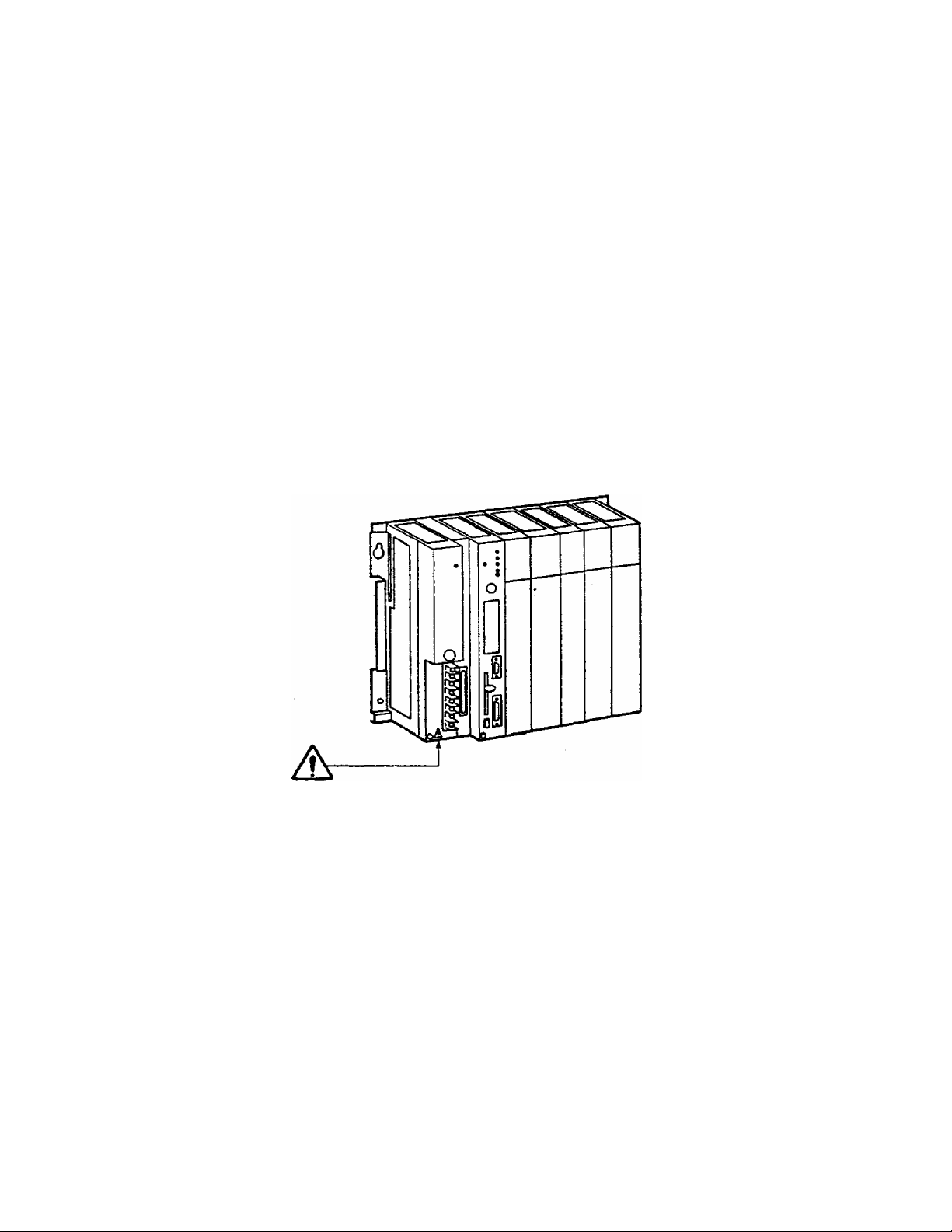
Safety Label
The safety label as shown on the right is
attached to the power terminal of the T3.
Safety Precautions
A CAUTION
Remove the mount paper before wiring.
Peel off the label from the mount paper
and stick It near the power terminals
where it can be readily seen.
Contact Toshiba if the label is damaged.
Do not touch terminals
A
Hazardous voltage can ^lock, bum or cause death.
Do not touch termirials while power on.
Read related manual thoroughly for safety.
Stick this seal on unit or near unit
Take off this sheet before wiring.
while power on.
3
User’s manual - Hardware V
Page 8

VI PROSEC ТЗ
Page 9

Before reading this manuai
FOR SAFETY To use the T3 safely, read this section carefully before use.
1. Only use the T3 after first carefully reading this Manual and
related guides.
2. Do not use in any of the following environments, as they will
cause malfunctions:-
(1 ) Where the ambient temperature of the T3 (the temperature
inside the panel) is 0"C or below or 55“C or above
(2) Where the ambient humidity of the T3 (the humidity inside the
panel) is 20% or less or 90% or more
(3) Where condensation may form due to severe changes of
temperature
(4) Where there are vibration or violent shocks
(5) Where there are corrosive gases or flammable gases
(6) Where there is dust,salinity or iron content
(7) Where there is direct sunlight
3. Pay attention to the following at the T3 installation site:-
(1 ) For safety in maintenance and operation, keep a distance of
at least 200mm from high-voltage equipment (high-voltage
lines) and power equipment (power lines), or separate by a
shield such as a steel plate.
(2) Keep the expansion cables separate from other povv'er
sources when wiring. In particular, separate by at least
200mm from high-power lines.
(3) Provide an air space of at least 70mm around the units for
ventilation.
(4) install the units vertically.
4. The T3 power supply module is a dedicated module for the T3.
Do not use it on its own for other purposes.
5. For the wiring to the module, use crimp-style terminals fitted with
reverse power sheaths. When it is not possible to use crimp-style
terminals fitted with sheaths, cover with insulating tape and
ensure that the conducting parts are<iot exposed.
User's manual - Hardware
1
Page 10
Before reading this manual
^ This is the warning mark for dangerous locations. It is attached
to the equipment in positions where there is a risk of electric
shock and in positions where there is a risk of damage to the
equipment through wrong wiring.
Take the following precautions where there is a A mark>
(1) Hazardous voltage can shock or cause severe injury if you
(2) For safety, always switch off power when wiring and during
(3) Wire the power input terminals correctly and do not apply
touch the power input terminals while power on. Do not
touch the power input terminals.
maintenance and inspections.
voltages in excess of the specified voltage limits, since this
will cause the equipment damege.
2 PROSEC T3
Page 11

Before reading this manual
The purpose of this
manual
This manual explains the hardware of the programmable controller
PROSEC T3. The explanation covers the configuration,
specification, installation, wiring, maintenance and service.
Scope of this manual This manual covers the following basic parts of the T3 system.
T3 main body: CPU module
Power supply module
Rack
Expansion interface module
Basic Dl/0 : 32 points DC input module (12-24 Vdc)
64 points DC input module (24 Vdc)
32 points AC input module (100-120 Vac, 200-240 Vac)
16 points DC output module (12-24 Vdc)
32 points DC output module (12-24 Vdc)
64 points DC output module (5-24 Vdc)
16 points AC output module (100-240 Vac)
32 points AC output module (100-240 Vac)
32 points relay output module (240 Vac/24 Vdc)
16 points isolated relay output module (240 Vac/24 Vdc)
User's manual - Hardware
Page 12

Before reading this manuai
Related manuals The following related manuals are available for the T3.
T3 User's Manual - Hardware
This manual covers the T3‘s main body and basic I/O - their
specifications, handling, maintenance and services.
T3 User's Manual - Functions
This document explains the functions of the T3 and how to use
them. The necessary information to create user program is covered
in this volume.
T-series Instruction Set
This manuai provides the detailed specifications of instructions for
Toshiba's T-series Programmable Controllers.
T-PDS Basic Operation Manuai
This manual explains how to install the T-series program
development system (T-PDS) into your personal computer and
provides basic programming operations.
T-PDS Command Reference Manual
This manual explains each command of the T-series program
development system (T-PDS) in detail.
T-series Computer Link Function
This manual explains the specification and handling method of the
T-series Programmable Controller's Computer Link function.
4 PROSEC T3
Page 13

Before reading this manuai
Note and caution
symbols
Terminology
Users of this manual should pay special attention to information
preceded by the following symbols.
NOTE Calls the reader's attention to information considered
important for full understandings of programming
procedures and/or operation of the equipment.
CAUTION Calls the reader's attention to conditions or practices that
could damage the equipment or render It temporarily
inoperative.
AWG American Wire Gage
ASCI! American Standard Code for Information Interchange
CPU Central Processing Unit
EEPROM Electrically Erasable Programmable Read Only Memory
IF Interface
I/O Input/Output
LED Light-Emitting Diode
ms millisecond
NEMA National Electrical Manufacturers' Association
PLC Programmable Controller
PS Power supply
RAM Random Access Memory
ROM Read Only Memory
jj. s microsecond
Vac ac voltage
Vdc dc voltage
User's manual - Hardware
Page 14

Contents
1. System Configuration.............................................................................. 9
1.1 T3 hardware configuration....................................................................... 9
1.2 Unit configuration ..................................................................................11
1.3 Power supply module
1.4 CPU module...........................................................................................15
1.5 Rack....................................................................................................... 19
1.6 Expansion interface module ..................................................................20
1.7 Expansion cable.....................................................................................21
1.8 List of I/O modules .................................................................................22
1.9 Examining the power supply capacity
2. Specification............................................................................................26
2.1 General specifications
2.2 External dimensions...............................................................................27
2.3 I/O module specifications
3. Precautions for I/O Modules...................................................................48
3.1 Precautions for DC input modules .........................................................48
3.2 Precautions for AC input modules
3.3 Precautions for DC output modules........................................................53
3.4 Precautions for AC output modules .......................................................55
3.5 Precautions for relay output modules ................................................... 56
............................................................................
....................................................
..........................................................................
......................................................................
........................................................
13
23
26
28
51
4. Installation and Wiring ...........................................................................57
4.1 Installation environment
4.2 Installing units ....................................................................................... 58
4.3 Mounting modules..................................................................................59
4.4 Connecting expansion units
4.5 Grounding...............................................................................................62
4.6 Wiring of the power supply
4.7 I/O wiring............................................................................................... 67
5. Maintenance and Checking....................................................................69
5.1 Daily checking items ............................................................................. 69
5.2 Periodical checking items ..................................................................... 70
5.3 Maintenance parts
5.4 Replacing battery ................................................................................. 71
5.5 Replacing fuses..................................................................................... 72
5.6 IC memory card handling
........................................................................
..................................................................
.....................................................................
...............................................................................
.....................................................................
57
60
65
71
74
6 PROSEC T3
Page 15

Contents
6. Troubleshooting..........................................................75
6.1 Troubleshooting procedure.....................................................................75
6.2 Checking the power supply
6.3 Checking the CPU..................................................................................77
6.4 Checking program.................................................................................. 77
6.5 Checking input........................................................................................78
6.6 Checking output......................................................................................79
6.7 Troubles due to external factors
6.8 I/O module replacement during operation .............................................81
6.9 List of self-diagnostic items
....................................................................
.............................................................
....................................................................
76
80
82
User s manual - Hardware 7
Page 16

1. System Configuration
8 PROSEC T3
Page 17
1. System Configuration
1.1
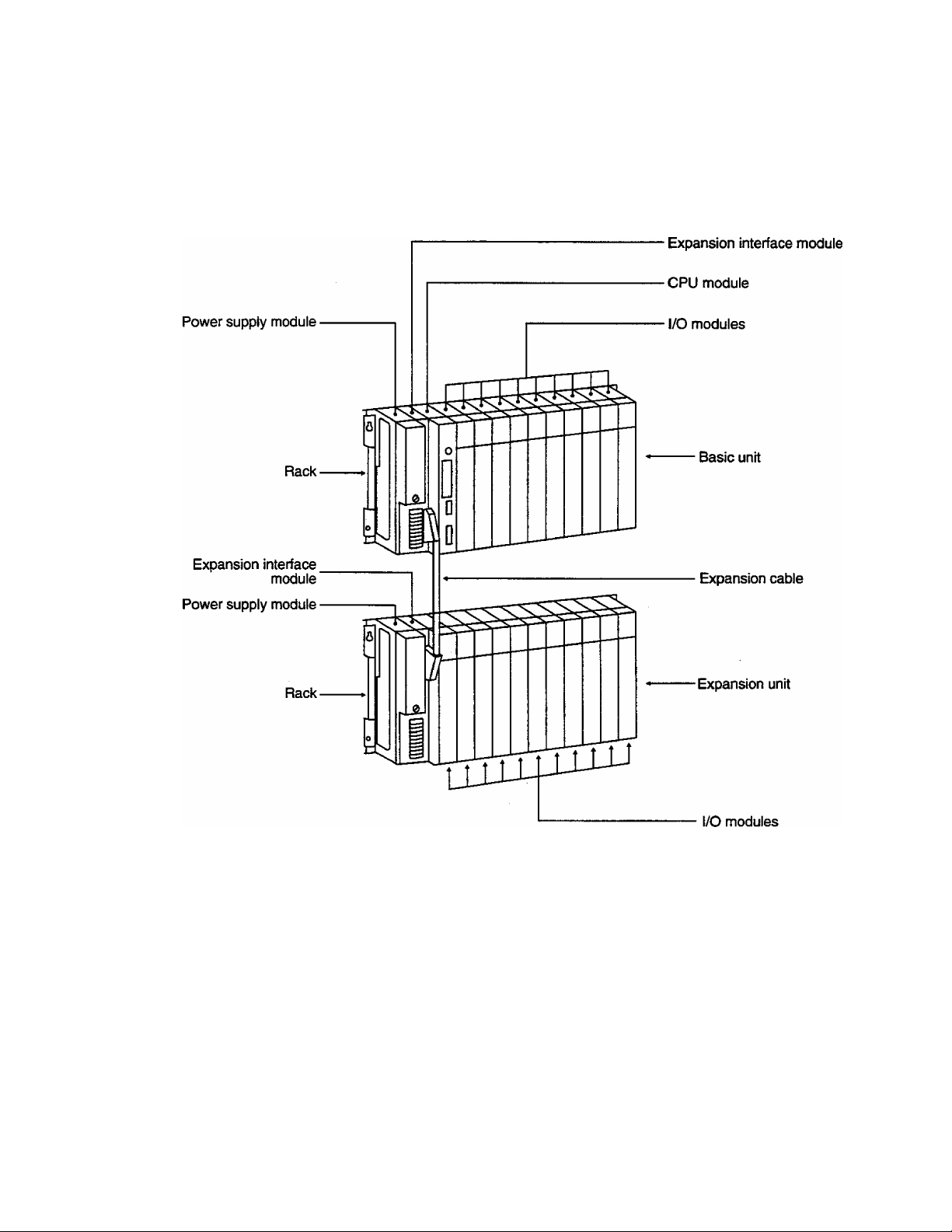
T3 hardware The T3 consists of the rack (s), the power supply modules (s), the
configuration CPU module, the expansion interface module (s), the expansion
cables (s) and I/O modules (s).
User's manual • Hardware
Page 18

1. System Configuration
The modules which configure the T3 system are listed below,
(except I/O modules)
Power supply module
CPU module
Rack
Type Description
PS361
1
2
PS332
Type
1
PU315 RAM
2 PU325
Type
1
BU31A
BU315
2
BU35B
3
4
BU356
Power supply voltage : 100-120 Vac/200-240 Vac,
common for basic and expansion units
Power supply voltage: 24 Vdc,
common for basic and expansion units
RAM+EEPROM
For basic
unit
For expansbn
unit
Description
Description
10 slots for I/O modules
5 slots for I/O modules
11 slots for I/O modules
6 slots for I/O modules
Expansion interface module
Type
1
IF311
2
IF351
3
IF312
4 IF352
IF353
5
For basic
unit
Fcx expansion
unit
For basic
unit
For middle
expan^n unit
For end
expansion unit
Description
Standard type,
2m maximum between the units,
total 6 m maximum
Long-distance type,
total 40 m maximum
Expansion cable
Type
1
CS3R5 0.5m
2 CS301 Im
CS302
3
4
CL3R5 0.5m
CL301
5
6 CU05 5m Long-distance type,
7 CL310
CL320
8
CL340
9
2m
1m
10m
20m
40m
Description
Standard type,
both-end connector (50-pin)
both^nd connector (68-pin)
10
PROSECT3
Page 19

1.2
Unit configuration
1. System Configuration
(1) Minimum configuration of the T3
c 1 1 1 1 1 i I 1 1 1
p
1
p
/ / / / / / / / /
s
/
u
0 0 0 0 0 0 0 0 0 0
Basic unit (10 t/0 rack)
320 points (32-point I/O)
Basic unit (5 I/O rack)
160 points (32-point I/O)
The minimum configuration of the T3 is one basic unit. In this
case, no expansion interface module is needed.
(2) Maximum configuration of the T3
Number of l/Q points (when 32point I/O modules are used)
320 points (10 I/O rack)
160 points (5 t/O rad()
1
672 points (11 I/O rack)
/
/ : / :
352 points (6 t/O rack)
0
1 (
1 I
1 (
1024 points (11 I/O rack)
544 points (6 I/O rack)
c 1 ! 1 1 1
p 1
1
p / / / / /
p
s
p 1
s
c¡1
c]
1
r
c
u 0
0
0 0 0 0
Expansion unit No.1
1 1 1 1 1 1 1
/ /
/ / /
0
0 0 0 0 0
Expansion unit No.2
Basic unit
11(1
(1(1
1 1 1 : 1 ; 1 : 1
/;/:/:/;/
0 : 0 : 0 ; 0 ; 0
till
(III
( ( ( 1
/
( 1
J 1
J 1
; 1 : 1 ; 1 ;
/
; / :
: 0 :
1 1
( 1
( (
1 1
1 1
1 1
0:0:
Expansion un t No.3
p
s F
□
i/1/1
!
0 0
/1/
0
0
1
/1/
0
o
1376 points (11 I/O rack)
736 points (6 I/O tack)
Up to three expansion units can be connected to the basic unit.
There is no limitation in combining different size of racks.
The expansion interface module is needed for each unit,
(indicated as "IF" in the figure)
The expansion interface module is dedicated for basic or
expansion units
User's manual - Hardware
11
Page 20

1. System Configuration
If the Standard type expansion is used, all expansion interface
modules must be the standard type. In this case, the maximum
length of the expansion cable is 2m between units, 6m total.
If the long-distance type expansion is used, all expansion
interface modules must be the long-distance type. In this case,
the maximum length of the expansion cable is total 40m.
If the standard type expansion is used, the necessity of the
power supply modules on the expansion units is determined
depending on the internal current consumption. (See 1.9
Examining the power supply capacity)
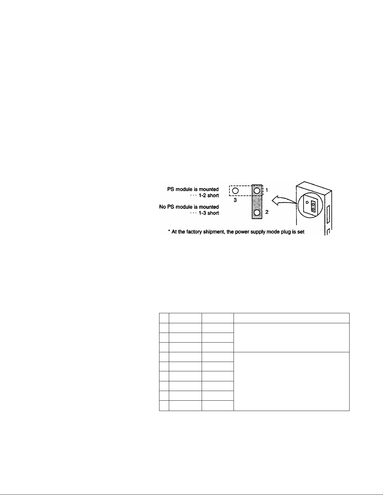
The power supply mode plug of the expansion interface module
must be set according to the power supply module mounting
status.
If the long-distance type expansion is used, all expansion units
should have the power supply modules.
The dedicated expansion cables are available for the standard
expansion and for the long-distance expansion, respectively.
12 PROSEC T3
Page 21
1.3
Power supply module
1. System Configuration
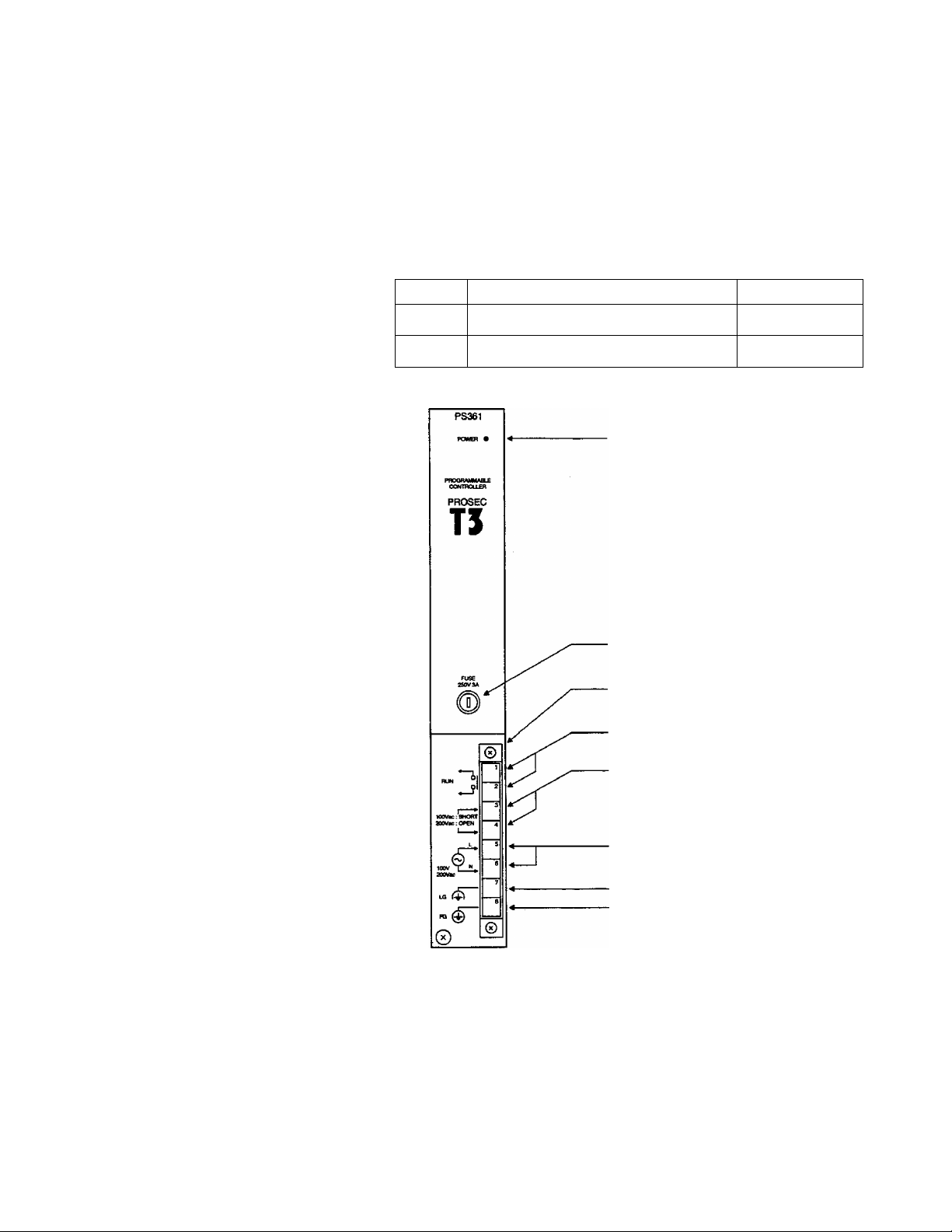
The following table shows that two types of power supply modules
are available, depending on the power supply voltage. These
modules can be used for both the basic unit and the expansion unit.
The power supply module is mounted in the extreme left of the rack.
However, the expansion rack that is connected to the standard
expansion IF may not need the power supply module. For details,
see 1.9 Examining the power supply capaci^.
Type
PS361
PS332
Rated voltage
100-120 Vac/200-240 Vac (selectable)
24 Vdc
POWER LED
Fuse
Tenninal block eject screw
(on top at bottom)
Run signal output terminals
Frequency
50/60 Hz
Voltage switch terminals
(100 to 120 Vac... ^ort\
1200 to 240 Vac... open)
Power su|:^ly input terminais
Line filter ground terminal
Frame ground terminal
\
Module fixing screw
User's manual - Hardware
13
Page 22

1. System Configuration
POWER LED (green):
This LED is lit when the internal 5 Vdc power supply is normal.
Fuse:
For PS361 ...250 Vac-3A (with one spare fuse)
For PS332...250 Vac-6A (with one spare fuse)
Run signal output terminals
Built-in NO contact which closes when T3 is in RUN mode.
Contact output...240 Vac/24 Vdc-2A (max.)
(can also be used on the expansion unit)
Voltage switch terminals:
These terminals are shorted or opened, depending on the power
supply voltage (with a short-circuit bar).
100 to 120 Vac...short
200 to 240 Vac...open
Power supply input terminals :
These terminals are used to connect the power supply line.
Line filter ground terminal (LG):
This terminal is a neutral point for the primary line filter of the power
supply, (grounding terminal)
Frame ground terminal (FG):
This terminal is connected to the frame of the T3. (grounding
terminal)
The terminal is connected, via a capacitor, to the signal ground (SG)
of the internal circuit.
CAUTION (1) Correctly set the voltage switch terminals, otherwise
▼AT
the module will be damaged.
(2) For details, see 2.1 General Specifications, for the
external power supply conditions.
(3) The screw size for the terminal is M3.5. For details
of the wiring, see 4.5, Grounding, and 4.6, Wiring of
the Power Supply.
14 PROSEC T3
Page 23
1. System Configuration
1.4
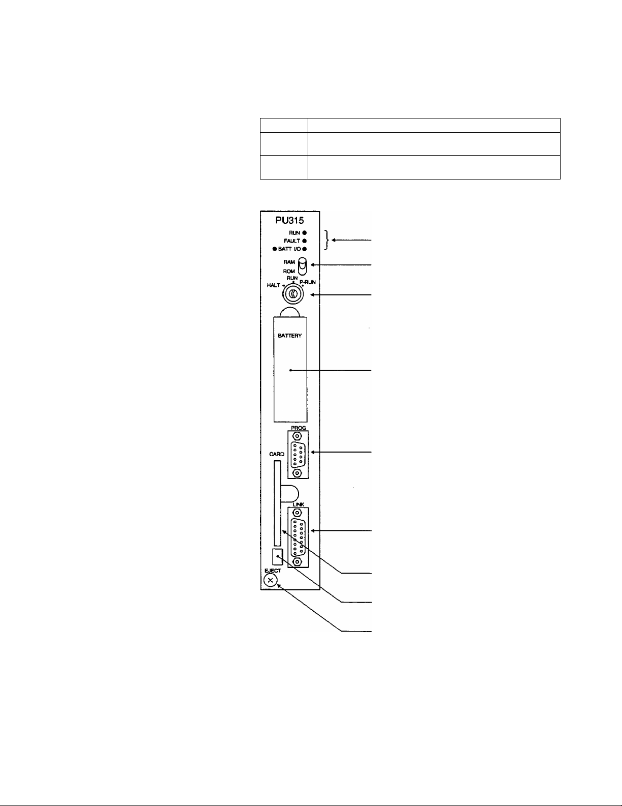
CPU module As shown in the table below, the CPU module is available in two
types.
Type Specification
PU315
PU325
PU315/PU325
RAM (battery backup), 32K steps for user program,
ladder diagram, SFC
EEPROM+RAM (battery backup), 32K steps for user program,
ladder diagram, SFC
Status display LED (RUN, FAULT. I/O, BATT)
RAM/ROM switch
Operation mode switch (HALT/RUN/P-RUN)
Battery cover
RS232C port for the programmer
(D-Sub 9-pin female connector)
RS485 port for the computer iink
(D-Sub 15-pin female connector)
1C memory card slot
IC memory card ejection button
Module fixing screw
User's manual - Hardware
15
Page 24

1. System Configuration
Status display LED:
Lit User program is executing (in the RUN mode)
RUN
(green)
Blink
Not lit Execution is stopped (in the HALT mode or in the ERROR mode)
Execution is stopped (in the HOLD mode)
Ut
FAULT
(red)
I/O
(red)
ВАТТ
(green)
Blink
Not lit
Ut
Blink Hardware initialization error
Not lit
Ut Normal battery voltage
Not lit Battery voltage becomes low
RAM/ROM switch
Position at
power ON
RAM
ROM
Typed
CPU
PU315
PU325
PU315
PU325
CPU/program error
Hardware initialization error
Normal
I/O error
Normal
Operation of the CPU
(program transfer at power ON)
Program transfer is not executed.
When an tC memory card which stores user program is
inserted, contents d the 1C memory card is transferred
to RAM. (When the operation mode switch is in P-RUN,
the program transfer is not executed.)
When an 1C memory card is not inserted or when the 1C
memory card does not contain a user program, program
transfer is not executed.
When an 1C memory card that stores user program has
been inserted, contents of the 1C memory card is
transferred to RAM. (When the operation mode switch
is in P-RUN, the program transfer is not executed.)
When an 1C memory card is not inserted, or when the 1C
memory card inserted does not contain a user program,
the contents of the EEPROM will be transferred to RAM.
(When the operation mode switch is in P-RUN, the
program transfer is not executed)
16 PROSEC T3
By using the RAM/ROM switch and the operation mode switch
together, the user can select a initial operation mode when power
is applied. For details,-see the next page.
Page 25

1. System Configuration
Operation mode switch :
Position of
the switch
User program execution is hatted (HALT mode).
HALT
RUN
P-RUN
Changing the operation mode by the programmer is invalid.
Normally programming is done in this state.
When the operation mode switch is changed to RUN,
the user program execution is started (the RUN mode).
Changing the operation mode from the programmer is possible.
When the operation mode switch is changed to P-RUN,
user program execution is started (the RUN mode).
Changing the operation mode from the programmer is possible.
The user program and leading 4K words of data registers (D)
are write-protected.
The table below shows the initial operation modes after power ON
depending on the Operation mode switch and RAM/ROM switch
status.
Function
RAM/ROM
switch
RAM
ROM
Mode
switch
HALT HALT
RUN HALT
P-RUN HALT
HALT
RUN
P-RUN RUN
Mode after
power on
HALT
RUN
Remarks
The CPU module is started in the HALT
mode and then waits for the RUN
command from the programmer,
or for a change-over of ttie operation
mode switch (->HALT->RUN).
The user program is transferred in
accordance with the conditions
mentioned in the table on the preceding
page.
The program transfer is not executed.
The CPU module is started based on
the contents of RAM.
NOTE (1) When power is turned on while the RAM/ROM switch
BAM, user program execution will not be started.
Regardless of the type of CPU module, therefore, the
RAM/ROM switch should be set to ROM for normal
operation.
(2) When the Operation mode switch is changed to RUN
while theRAM/ROM switch is in ROM, the program
transfer is executed, according to the conditions
mentioned in the table on the preceding page, before
the CPU module starts operation.
(3) For details on operation modes, see "T3 User's
Manual-Functions" in a separate volume.
User's manual - Hardware 17
Page 26

1. System Configuration
Battery cover:
A batteiy has been installed inside this cover at the factory
shipment. The battery keeps the RAM contents (user program and
user data) and supports the clock-calendar operation during power
OFF.(See 5.4 Replacing battery)
RS232C port for the programmer :
The T-series programmer (T-PDS or HP911) is connected to the T3
through this port. Dedicated connection cables are available.
RS485 port for the computer link:
The CPU module has the computer link function as standard.
By using this function, T3 can communicate with a host computer or
an intelligent equipment through RS485 interface. For details of the
computer link function, see separate "T-series Computer Link
Funciton Operation Manual".
IC memory card slot:
Optional !C memory card (type : ME914) is inserted into this slot.
By installing the IC memory card, user program back-up/switchover
or user data expansion become available. Refer to 5.6 IC memory
card handling.
18 PROSEC T3
Page 27

1.5
Rack
1. System Configuration
As described in the table below, in total four racks are available :
two racks are for the basic unit, and two racks, for the expansion
unit.
Type
BU31A
BU315
BU35B
BU356 PS X1,IF X1,I /0X6
Use
For
basic
unit
For
expansion
unit
Number of modules mountable
PSX1, IFX1, CPUX1,1/0X10
PS XI.IF XI.C PUX I, 1/0X5
PS XI.IF XI, 1/0X11
) "PS" and "IF" in the above table indicate the power supply
module and the expansion interface module respectively.
I II I I I
BU315
BU356
• The connector on the extreme-left slot of the rack is dedicated to
the power supply module, and the connector next to the right
slot is dedicated to the expansion interface module. The third
connector from the extreme left slot of the basic unit rack
(BU31A, BU315) is dedicated to the CPU module.
CAUTION Place a cap on each of the connectors where no module
is mounted so that no foreign material will enter.
User's manual - Hardware
19
Page 28

1. System Configuration
1.6
Expansion interface
module
If the expansion units are used, the expansion interface modules
must be mounted in each of the basic unit and the expansion units.
There are basically two types of expansion interface modules-the
standard type and the long-distance type. What type to use will
depend on the cable distance. The dedicated expansion interface
module must be mounted on each of the basic unit and the
expansion units.
Type
IF311
IF351
IF312
IF352
IF353
Use
For
basic unit
For
etqjansion unit
For
basic unit
For middle
expansion unit
For end
expansion unit
IF311
(standard type, tor basic unit)
iF311
OUT
iS.
Standard type
2m maximum between two units,
6m maximum in total cable length
Long-distance type
40m maximum in total cable length
(standard type, for expansion unit)
Expansion connector (IN)
Connected to tiie preceding unit
Expansion connector (OUT)
Connected to the next unit.
Remark
IF351
1F351
&
V
IN
OUT
20 PROSEC T3
Page 29
1. System Configuration
Since there is no compatibility between the standard type and
the long-distance type, these two types cannot be mixed in one
T3 configuration.
The standard type expansion cable and the long-distance type
expansion cable are not compatible with each other. (See
Section 1.7 Expansion Cable.)
If the standard type is used, whether a power supply module is
necessary for the expansion unit will depend on the internal 5
Vdc current consumption. (See Section 1.9 Examining the
power supply capacity.)
For the IF351, change the power supply mode plug as shown in
the figure below (depending on whether a power supply module
has been mounted on its own unit).
IF351
1.7
Expansion cable
to 1-2 shorted (witii a power supply).
For the long-distance type, a power supply module is needed for
each of the expansion units.
In the long-distance type, the IF312 is for basic unit, the IF352 is
for middle expansion units and the IF353 is for the end
expansion unit.
The following types of expansion cables are available.
Type
1
CS3R5
2
CS301
3
CS302 2m
4
CL3R5 0.5m
.5
GL301 1m
6
CL305
7
CL310
8
CL320 20m
9
CL340 40m
Cable length Remarks
0.5m
1m
5m
10m
Standard type
With both-end connectors (50-pin)
Long-distance type
With both-end connectors (68-pin)
Front
User’s manual - Hardware
21
Page 30

1. System Configuration
1.8
List of I/O Modules
This manual explains the basic I/O modules in the list below and
how to use them.
Type
DI334
DI334H
D1335
DI335H
IN354
IN364
D0333
D0334
D0335
AC363
AC364
R0364
R0363S
DC
input
AC
input
DC
output
AC
output
Relay
output
Specification
32 points (8 pts common), 12 to 24 Vdc,
10 mA/point
32 points (8 pts common), 12 to 24 Vdc,
10 mA/point, high-speed response
64 points (8 pts common), 24 Vdc,
5 mA/point
64 points (8 pts common), 24 Vdc,
5 mA/point, high-speed response
32 points (8 pts common), 100 to 120 Vac,
10 mA/point
32 points (8 pts common), 200 to 240 Vac,
10 mA/point
16 points (8 pts common), 12 to 24 Vdc,
2 A/point, 5 A/common
32 points (16 pts common), 12 to 24 Vac,
0.5 A/point, 5 A/common
64 points (8 pts common), 5 to 24 Vdc,
100 mA/point
16 points (8 pts common), 100 to 240 Vac,
2 Appoint, 5 A/common
32 points (16 pts common), 100 to 240 Vac,
0.5 A/point, 3.2 A/common, 5 A/module
32 points (8 pts common), 240 Vac/24 Vdc,
2 A/point, 5 A/common
16 points (isolated contact), 240 Vac/24 Vdc,
2 A/point
22 PROSEC T3
For details on the specification of I/O modules, see 2.3, I/O
module specifications.
Carefully read the Cautions described In Section 3 for applying
I/O modules.
The I/O module can be mounted in any I/O slot functionally.
However, to improve noise-immunity for the entire system, it is
recommended to separate the low voltage 1/Os and the power
I/Os. (See 4.7, I/O Wiring.)
Page 31

1.9
Examining the power
supply capacity
1. System Configuration
The maximum output current (5 Vdc) of the power supply module
(PS361/PS332) is 7 A. (5.1V at factory setting)
In the standard type expansion configuration, if the power supply
module of the previous unit can supply 5 Vdc to the following units,
no power supply module for the following expansion units is
necessary.
In this case, however, there may be a voltage drop of the 5 Vdc
power caused by the resistance of the expansion cable. The
minimum limit voltage is 4.75 Vdc. It should also be considered.
Basic unit
Internal S Vdc current
consumption
^PU+IF+l/0 {A)=lo[A]
Exfsansion cable
resistance
= Ro [Q]
Internal 5 Vdc current
consumption
==IF+l/0 (BHi[A]
Expansion cable
resistance
= Ri [Q]
internal 5 Vdc current
consumption
=IF+l/0 (C)=l2[A]
Expansion cable
resistance
= R2 [Q]
Internal 5 Vdc current
consumption
=IF+l/0 (D)=l3lA]
Concerning the above figures, the following conditions (1) and (2)
must be satisfied so that the expansion units N0.1 through 3 can be
mounted in the slots using no power supply of their own.
(1) lo+li+l2+l3<7A
(2) 5.1-RoX(li+l2+l3)-RiX{h+l3)-R2Xl3> 4.75V
If either of the above conditions is not satisfied, a power supply
module is needed for the expansion unit.
If a power supply module is mounted on the expansion unit, the
power supply module will supply 5 Vdc to the own unit and to the
following expansion units, disconnecting 5 Vdc line from the
previous unit (OV line is common).
User's manual - Hardware
23
Page 32

1. System Configuration
For example, if the user is going to mount a power supply module
on the expansion unit No.2, check that the following conditions are
satisfied.
(1) lo+li<7A
(2) 5.1-RoXh > 4.75V
(3) l2+l3 < 7A
(4) 5.1-R2Xl3>4.75V
Additional power supply modules may be mounted on the units
even though the power supply capacity has enough margin.
NOTE (1) Correctly set the power supply mode plug of the
\~ZiX7 expansion interface module (IF351) according to a
Conditions for the power supply
capacity of the basic unit
Conditions for the power supply
capacity of expansion unit No.2
power supply module to be mounted on the unit. If
the setting is wrong, the T3 will not work normally.
(For details, see 1.6 Expansion interface module.)
(2) For the long-distance expansion interface module,
each of the units must be equipped with a power
supply module.
The table below shows the resistance values (typical value) of
expansion cables.
Cable
length
0.5m
1m
2m
Part No.
CS3R5
CS301
CS302
Resistance
value
38m Q
66m Q
112mQ
Remarks
Standard type
With both-end connectors
(50-pin)
24 PROSEC T3
Page 33

1. System Configuration
The table below lists the internal 5 Vdc current consumption (max.)
of the module for calculating allowable power capacity.
Internal 5-
Type
Expansion
interface
CPU
DC
input
AC
input
DC
output
AC
output
Relay
output
Special
I/O
Data link
Name
Standard expansion interface
(for basic unit)
Standard expansion interface
(for expansion unit)
Long-distance expansion interface
(for basic unit)
Long-distance expansion interface
(for middle expansion unit)
Long-distance expansion interface
(for end expansion unit)
CPU (RAM)
CPU (EEPROM+RAM)
32-point DC input
32-point DC input
(high-speed response)
64-point DC input
64-point DC input
(high-speed response)
32-point AC input (100 to 120 Vac)
32-point AC input (200 to 240 Vac)
16-point DC ou^ut (12 to 24 Vdc)
32-point DC output (12 to 24 Vdc)
64-point DC output (5 to 24 Vdc)
16-point AC output (100 to 240 Vac)
32-point AC ou^ut (100 to 240 Vac)
32-point relay output
10-point relay output (Isolated)
Analog Input (8 channels)
Analog output
(4 channels)
Pulse input (2 channels)
DC input (8 pts) with status change
detection
ASCII interface
TOSL1NE-S20
TOSLINE-F10 (master)
Voltage
Current DA374 180 mA
Coaxial
Optic
Coaxial/optic
Part No.
IF311 20 mA
IF351 20 mA
IF312 800 mA
IF352 700 mA
IF353 700 mA
PU315 2.5 A
PU325 2.5 A
DI334 100 mA
DI334H 100 mA
DI335 170 mA
DI335H
IN354
IN364 120 mA
D0333
D0334 210 mA
D0335
AC363
AC364 800 mA
R0364 170 mA
R0363S 100 mA
AD368
DA364
P1312 800 mA
CD332 300 mA
AS311
SN321 800 mA
SN322 800 mA
SN323 800 mA
MS311
volt current
ccxisumption
170 mA
120 mA
320 mA
400 mA
530 mA
460 mA
180 mA
1 A
1 A
Note) The current consumption of the T3 CPU modules (2.5 A max.) is
the value when the handy programmer (HP911) is connected.
When the HP911 is not connected, it is 1.5 A max.
User's manual - Hardware
25
Page 34

2. Specification
2.1
General Specifications
Item Specification
Rated
voltage
Voltage
tolerance
Rated
>.
o.
frequency
CL
3
ai
Frequency
k.
<i)
tolerance
1
CL
Retentive power
Interruption
Power
consumption
Inrush
current
Insulation
resistance
Withstand
voltage
Operating
temperature
Storage
temperature
Ambient
humidity
(1) 100 to 120 Vac/200 to 240 Vac
(2) 24 Vdc
(1) 85 to 132 Vac/170 to 264 Vac
(2) 20.4 to 28.8 Vdc
(1)50/60 Hz
(1)47 to 63 Hz
10 ms or less
(1) 80 VA or less
(2) 50 W or less
(1) 10 A/100 Vac, 20 A/200 Vac
(2) 6 A
10 MQ or more (500 Vdc)
1500 Vac for 1 minute
0 to 5Sr
-20 to 75*C
20 to 90% RH
Remarks
Switchable
Max. load
conditions of one
PS module
Between power
terminals and FG
Between power
terminals and FG
No condensation
26 PROSEC T3
Atmosphere No corrosive gases
Dust
Vibration
immunity
Shock
immunity
Noise
immunity
Grounding
Structure
Cooling
10 mg/m3 or less
16.7 Hz, 3 mmp-p, 30 seconds
98 m/s2, 3 times, in X, Y, Z
directions
1500 Vp-p, 1 M s (noise simulator
method) NEMA ICS3-304
100Q or less
Control panel built-in t^
Natural cooling
Approx. 7.6 kg
Weight
Approx. 4.7 kg
No power
No power
Power supply noise
Basic unit with
10 I/O modules
Basic unit with
five I/O modules
Page 35

2.2
External Dimensions
2. Specification
Basic unit (10 I/O slots)
4-^6
Expansion unit (11 I/O slots)
4-^6
Basic unit (5 I/O slots)
4-^6
Expansion unit (6 I/O slots)
4^^6
User's manual - Hardware
units: mm
27
Page 36

2. Specification
I/O module
specifications
32-point DC input
2.3
Type
Category
input type
Number of input points
insulating method
Rated input voltage
Range of input voltage
Rated input current
Input impedance
Opera
tion
voltage
Delay
Min. ON voltage
Max. OFF voltage
OFF-ON
ON — OFF
Input signal display
External connection
No. of commons
No. of input points
per common
Polarity of common
Derating condition
Internal cunent
consumption
Insulation resistance
Withstand voltage
Weight
Internal circuit
DI334
DC input
Current sinking/sourdng
32 points. 2-word input (X 2 W)
Photo-coupler
12to24Vdc
10 to 26.4 Vdc
10 mA (at 24 Vdc)
2.4 KQ (at 24 Vdc)
9.6V
3.5V
10 ms or less
15 ms or less
LED display for all points, lit at ON, internal logic side
38-pin removable tenninal block, M3.5
4 (insulated between commons)
8 points/common
No Polarity
See NOTE on the next pate
5 Vdc, 100 mA or less
10 MQ or more (500 Vdc)
1500 Vac, 1 minute (between commons, between
internal and external circuits)
420g
DI334H
1 ms or less
1.5 ms or less
28 PROSEC T3
Page 37

2. Specification
32-point DC input
(cont'd)
Terminal connections
—^S)— Input power "Hh" 12 to 24 VdC
supply |^|j
NOTE The number of simultaneous ON input points will be
restricted according to the ambient temperature and
input voltage, as described in the figure below.
Number of simultaneous ON input points
Amt»ent temperature
(C)
User's manual - Hardware 29
Page 38

2. Specification
64-point DC input
30 PROSEC T3
Page 39

64-point DC input
(cont'd)
2. Specification
NOTE Type of the connector of the module side:
FCN-365P040-AU (Fujitsu)
Connectors (2, soldering types) of the cable side are
attached as standard.
User's manual - Hardware
31
Page 40

2. Specification
32-point AC input
Type
Category
Number of input points
insulating method
Rated input voltage
Range of input voltage
Frequency
Rated input current
input impedance
Opera
tion
voltage
Min. ON voltage
Max, OFF voltage
OFF - ON
Delay
ON — OFF
Input signal display
External connection
No. of commons
No. of input points
per common
Derating condition
Internal current
consumption
insulation resistance
Withstand voltage
Weight
Internal circuit
IN354
AC input
32 points, 2-word input (X 2 W)
Photo-coupler
100 to 120 Vac
85 to 132 Vac
50/60Hz(47to63Hz)
10mA(at100Vac,50Hz)
10 KQ (50Hz),
8 KQ (60Hz)
70 Vac
25 Vac
15 ms or less
15 ms or less
LED display for all points, lit at ON, internal logic side
38-pin removable terminal block, M3.5
4 (insulated between commons)
8 points per common
None
5 Vdc, 120 mA or less
10 M Q or more (500 Vdc)
1500 Vac, 1 minute (between commons, between
internal and external droiits)
480g
200 to 240 Vac
170 to 264 Vac
10 mA (at 200 Vac, 50Hz)
22 kD (50 Hz),
18 kQ (60 Hz)
140 Vac
50 Vac
IN364
32 PROSEC T3
Page 41

2. Specification
32-point AC input
(cont'd)
Terminal connections
Input power
supply
too to 120 Vdc
200 to 240 Vdc
User's manual - Hardware 33
Page 42

2. Specification
16-point DC output
Type
Category
Output type
No. of output points
Insulating method
Rated input voltage
Range of load voltage
Max. load current
Voltage drop at ON
Leakage current at OFF
Delay
Output signal display
Module status display
External connection
No. of commons
No. of output points
per common
Common polarity
Derating condition
Internal current
consumption
Insulation resistance
W№stand voltage
Built-in fuse
Surge suppressor
Weight
Internal circuit
OFF - ON
ON — OFF
D0333
Transistor output
Current sinking
16 points, 1-word input (Y 1 W)
Photo-coupler
12 to 24 Vdc
10to30Vdc
2 A/point, 5 A/common
1.5 V or less (at 24 Vdc)
0.1 mA or less (at 24 Vdc)
1 ms or less
1 ms or less
LED display for all points, lit at ON, internal logic side
Fusing/extemal abnormal power supply LED
(FL, FH), lit at abnormal state
20-pin removable terminal block, M3.5
2 (insulated between commons)
8 points per common
negative (-) polarity
See NOTE on the next page
5 Vdc, 320 mA or less
10 MQ (500 Vdc)
1500 Vac, 1 minute (between commons, between
internal and external drcuits)
6 A/commonX2
Diode
41 Og
_______________
34 PROSEC T3
Page 43

2. Specification
16-point DC output
(cont'd)
Terminal connections
—□□—
_ 1
_ . 1
. 1
_ . 1
-........1
--------1
___
--------I
___
]
------
1
___
1
-----
1
___
1
-----
____
-------1
___
1
-----
1
___
1
___
------
1
___
1
___
1
-----
1
___
1
-----
1
___
1
___
1
1
1
1
1. ..
t
1
1
1
1
i
i
i
1
1
1
1
1
1
1
1
1
1
_ll
_____
u
1
2
3
4
5
6
7
LP
I ■
11
LC
A
B
C
D
B
F
HP
HC
10
e
11
9
12
13
14
15
16
17
18
_||_
19
20
Load pow№ SLpply:
12to24Vdc
NOTE The maximum load current has the following restrictions,
depending on the ambient temperature.
Load currant
GO Ambient temperature
rC)
User's manual - Hardware
35
Page 44

2. Specification
32-point DC output
Type
Category
Output type
No. of output points
Insulating method
Rated load voltage
Range of load voltage
Max. load current
Voltage drop at ON
Leakage current at OFF
Delay
Output signal display
Module status display
External connection
No. of commons
No. of output points
per common
Common polarity
Derating condition
Internal current
consumption
Insulation resistance
Withstand voltage
Built-in fuse
Surge suppressor
Weight
Internal circuit
OFF - ON
ON - OFF
D0334
Transistor output
Current sinking
32 points, 2-word output (Y 2 W)
Photo-coupler
12 to 24Vdc
10 to 30Vdc
0.5 A/point, 5 A/common
1.5 V or less
0.1 mA or less (at 24 Vdc)
1 ms or less
1 ms or less
L£D display for all points, lit at ON, internal logic side
Fusing/extemai abnormal power supply LED
(FL. FH), lit at abnormal state
38-pin removable terminal block, M3.5
2 (insulated between commons)
16 points per common
negative (-) polarity
See NOTE on the ne)d page
5 Vdc, 210 mA or less
10 MQ (500 Vdc)
1500 Vac, 1 minute (between commons, between
internal and external circuits)
6 A/common X2
Diode
530g
_________
36 PROSEC T3
Page 45

2. Specification
32-point DC output
(cont'd)
Terminal connections
Load power supply :
Hi-
12to24Vdc
NOTE Maximum load current has the following restrictions,
depending on the ambient temperature.
Load current
0.5 A/point
5 A/common
10 20 30 40 50 60 Ambient temperature
0.4 A/point
4 A/common
CC)
User's manual - Hardware 37
Page 46

2. Specification
64-point DC output
Type
Category
Output type
No. of output points
Insulating method
Rated input voltage
Range of load voltage
Max. load current
Voltage drop at ON
Leakage current at OFF
Delay
Output signal display
Module status display
Externa! connection
No. of commons
No. of output points
per common
Common polarity
Derating condition
Intemai current
consumption
insulation resistance
Withstand voltage
Built-in fuse
Surge suppressor
Weight
Intemai circuit
OFF - ON
ON — OFF
D0335
Transistor output
Current sinking
64 points, 4-word output (Y 4 W)
Photo-coupler
5 Vdc/12 to 24 Vdc
4.5 to 9.5 Vdc/9-6 to 26.4 Vdc
0.1 A/point (9.6 to 26.4 Vdc)
0.05 A/point (4.5 to 9.5 Vdc)
0.4 V or less
0.1 mA or less (at 24 Vdc)
1 ms or less
1 ms or less
LED display for ali points, lit at ON, intemai logic side
None
40-pin connectorX2
8 (insulated between commons)
8 points per common
negative (-) polarity
None
5 Vdc, 400 mA or less
10 MO or less (500 Vdc)
1500 Vac, 1 minute
(between intemai and external circuits)
None
Diode
550g (including connectors)
38 PROSEC T3
CN1
CN2
Page 47

64-point DC output
(cont'd)
2. Specification
NOTE Type of the connector on the module side :
FCN-365P040-AU (Fujitsu)
The connectors (two, soldering types) of the cable side
are attached as standard.
User's manual - Hardware
39
Page 48

2. Specification
16-point AC output
Type
Category
No. of output points
Insulating rpethod
Rated load voltage
Range of load voltage
Max. load current
Voltage drop at ON
Leakage current at OFF
Min. load current
Max. innjsh current
Delay
Output signal display
Module status di^lay
External connection
No. of commons
No. of output points
per common
Derating condition
Internal current
consumption
insulation resistance
Withstand voltage
Built-in fuse
Surge suppressor
Weight
Internal circuit
OFF — ON
ON OFF
AC363
Triac output
16 points, 1-word output (Y 1 W)
Photo-coupler
100 to 240 Vac (50/60 Hz)
24 to 264 Vac (47 to 63 Hz)
2 A/points, 5 A/common
1.5 V or less
1.0 mA or less (at 100 Vac, 50 Hz)
2.4 mA or less (at 200 Vac, 60 Hz)
100 mA (24 Vac), 50 mA (100 to 240 Vac)
20 A/20 ms (point), 40 A/20 ms (common)
1 ms or less
1 ms+1/2cycle or less
LED di^lay for all points, iit at ON, interna) logic side
Fusing display LED (FL, FH), lit at fusing
20-pln removable terminal block, M3.5
2 (insulated between commons)
8 points per common
See NOTE on die next page
5 Vdc, 530 mA or less
lOMQor less (500 Vdc)
1500 Vac, 1 minute (between commons between
interna) and external circuits)
6 A/common X2
CR snubber circuit, varistor
500g
40 PROSEC T3
Page 49

16-poìnt AC output
(cont'd)
2. Specification
NOTE Maximum load current has the following restrictions,
depending on the ambient temperature.
Load current
40 50 60 Ambient temperature
(t)
User's manual - Hardware
41
Page 50

2. Specification
32-point AC output
Type
Category
No. of output points
Insulating method
Rated load voltage
Range of load voltage
Max. load current
Voltage drop at ON
Leakage current at OFF
Min. load current
Max. inrush current
Delay
Output signal display
Module status display
External connection
No. of commons
No. of output points
per common
Derating condition
Internal current
consumption
Insulation resistance
Withstand voltage
Built-in fuse
Surge suppressor
Weight
Internal circuit
OFF —ON
ON — OFF
AC364
Triac output
32 points, 2-word output (Y 2 W)
Photo-coupler
100 to 240 Vac (50/60 Hz)
24 to 264 Vac (47 to 63 Hz)
0.5 A/point, 3.2 A/common, 5 A/modute
1.5 V or less
0.8 mA or less (at 100 Vac, 50 Hz)
1.6 mA or less (at 200 Vac, 50 Hz)
100 mA (24 Vac), 50 mA (100 to 240 Vac)
20 A/20 ms (points and common)
1 ms or less
1 ms+1^cycle or less
LED display for all points, lit at ON, internal logic side
Fusing display LED (FL, FH), lit at fusing
38-pin removable terminal block, M3.5
2 (insulated between commons)
16 points per common
None
5 Vdc, 800 mA or less
10 MQ or less (500 Vdc)
1500 Vac, 1 minute (between commons, between
internal and external circuits)
6 A/commonX2
CR snu№er circuit
540g
42 PROSEC T3
Page 51

2. Specification
32-point AC output
(cont'd)
Terminal connections
Load power supply
100to240Vdc
NOTE Minimum 24 Vac can be used as the load voltage.
However, if ioad voltage becomes 85 Vac or less, the
fusing detection circuit may work, in this case, aithough
AC output operation has no problem, the fusing display
LED (FL, FH) will light.
User's manual - Hardware 43
Page 52

2. Specification
32-point relay output
Type
Category
Output
No. of output points
Insulating method
Rated toad voltage
Range of load voltage
Max. load current
Contact ON resistance
Leakage current at OFF
Min. load current
Delay
Output signal display
Module status display
External connection
No. of commons
No. of output points
per common
Internal current
consumption
External
power
for relay
Mechanical life
Electrical contact life
insulation resistance
Withstand voltage
Built-in fuse
Weight
Internal drcuit
OFF ON
ON — OFF
Rated voltage
Rated current
Voltage range
R0364
Electromechanical relay output
NO-contact
32 points, 2-word output (Y 2 W)
Photo-coupler
240 Vac/24 Vdc
Up to 264 Vac/125 Vdc
2 A/point (resistive load), 5 A/common
50 mQ or less (initial value)
None
5 Vdc, 10 mA (50 mW or more)
10 ms or less
10 ms or less
LED display for all points, lit at ON, internal logic side
^normal external power suF^ly display LED (F),
tit at abnormal state
38-pin removable terminal block, M3.5
4 (insulated between commons)
8 points per common
5 Vdc, 170 mA or less
24 Vdc
300 mA (24 Vdc, at all points ON)
21.6 to 26.4 Vdc
20 million times or more
See the next page
10 MQ or more (500 Vdc)
1500 Vac, 1 minute (between commons, between
internal and external circuits)
None
51 Og
_____
44 PROSEC T3
OCOM
Page 53

2. Specification
32-point relay output
(cont'd)
Terminal connections
Load poMer supply
240Vai/24Vdc
Hi- 24Vdc for relay
driving
SwitcNng life
(10,000 bTnes)
NOTE The following figures indicate life curves of the output
relay. The data are based on 1800 switching times/hour.
For more frequently operation, the life of the output relay
will become shorter.
AC load
Switchirig life
(10,000 times)
DC load
Switching
Cunent
User's manual - Hardware 45
Page 54

2. Specification
16-point isolated relay
output
Type
Category
Output type
No. of output points
Insulating method
Rated load voltage
Range of load voltage
Max. load current
Contact ON resistance
Leakage current at OFF
Min. load current
Delay
Output signal display
Module status display
External connection
Common connection
Internal current
consumption
External
power
for relay
Mechanical life
Electrical contact life
Insulation resistance
Withstand voltage
Built-in fuse
Weight
Internal circuit
OFF - ON
ON OFF
Rated voltage
Rated current
Voltage range
R0363S
Electromechanical relay output
NO-contact
16 points, 1-word output (Y 1 W)
Photo-coupler
240Vac/24Vdc
Up to 264 Vac/125 Vdc
2 A/point
50 mQ or less (initial value)
None
5 Vdc, 10 mA (50 mW or more)
10 ms or less
10 ms or less
LED di^lay for all points, lit at ON, internal logic side
^normal external power supply display LED (F),
lit at abnormal state
38-pin removable terminal block, M3.5
16-point isolated contact
5 Vdc, 100 mA or less
24 Vdc
145 mA (24 Vdc, at all points ON)
21.6 Vdc to 26.4 Vdc
20 million times or more
See the next page
10 MQ or more (500 Vdc)
1500 Vac, 1 minute (between the points, between
internal and external circuits)
None
450g
46 PROSEC T3
Page 55

2. Specification
16-point isolated
relay output
(cont'd)
Terminal connections
Load power suppty
240Vac/24VdC
:
-J|_ 24Vdc for retay
' driving
Switching life
(10,000 tiines)
NOTE The following figures indicates life curves of the output
relay. The data are based on 1800 switching times/hour.
For more frequently operation, the life of the output relay
will become shorter.
AC load
Switching life
(10,000 times)
DC load
0,2 0.3 0.5 0.7
1.5 2 Current
Swit^ng
User's manual - Hardware
47
Page 56

3. Precautions for I/O Modules
3.1
Precautions for DC
Input modules
(1) Read conditions for the ON/OFFchanges of the input signals are:
Input ON time^ON delay time (OFF->ON)+lnput reading cycle
input OFF time^OFF delay time (ON->OFF)+lnput
Where the “input reading cycle“ means PLC scan cycle for the
refresh input, or the execution interval of a direct input instruction
when the instruction is used.
(2) For some external contacts, the input current (10 mA/24V for
DI334; 5 mA/24V for DI335) of modules may not be able to
maintain contact reliability. In this case, install a bleeder resistor
between the input and common terminals to increase the contact
current.
(An example of selecting a bieeder resistor R)
Input voltage V=24 Vdc
Input module DI334 (10 mA/24 Vdc)
When the contact requires 50 mA current;
Resistance value R of a bleeder resistor=0.6[kQ]
Wattage P of the bleeder resistor=3[W]
y-
reading cycle
Contact Input module
—
---
------
0 O—'
t
”
—\
ill
COM
II
V
wi
Wattage P> X(2.5~3)
R
48 PROSEC T3
(3) If a switch with an LED display is used, the current (leakage
current) through the LED may cause the erroneous input (always
ON). In this case, install a bleeder resistor to lower the input
impedance.
LED
(Example of selecting a bieeder resistor R)
When the voltage between input terminals is Vd at the switch
OFF state (with no bleeder resistor), the resistance (R) and the
wattage (P) of the bleeder resistor can be selected as follows.
Page 57

3. Precautions for I/O Modules
(V-Vd) Vo
R<
V(Vd-Vo)
P= (2.5~3)
In case of DI334,
V=24 Vdc, Vo=3-5 Vdc, Zi=2.4 kCl
If Vd=5 Vdc, R can be calculated as follows.
R[kQ]<_l
As a result,
R<4.4[kQ]->3kQ
P=(2.5~3)X
Also, when the bleeder resistor is selected in the above manner,
the contact current at the switch ON state should be checked.
Contact current=24[V]X
(4) If the two-wire proximity switch and other solid-state switches
are used, be sure that there is no possibility of mis-inputting
because of the leakage current, as in procedure (3). (See (3) for
details on how to select a bleeder resistor.)
Also in this case, because of the effect of the saturation voltage
(voltage drop) at ON, regardless of whether the switch is ON,
the input terminal voltage may not be able to reach the ON
voltage, thereby failing to read as input ON.
if input voltage is low or if input wiring is too long, special
measures are necessary.
Two-wire proximity switch , ^ module
(24-5) X3.5
----------1-----24X(5-3.5)
2 V: Input voltage
yL
R
X2.4IkQ]
{2AW
3000[Q]
Vo: Max. OFF voltage of the input module
Z i: Input impedance of the input module
0.5W
2.4IkQ]+R
2.4[kQ]XR
^18[mA]
Cable resistance (R) moouie
■ CD---
----------
6
if the cable resistance value is expressed as R[Q], Vd[V] for the
voltage drop of the proximity switch, and Zi[Q] for the input
impedance of the input module, the voltage Vi[V] applied
between the input module terminals will be as expressed below
(when the proximity switch is ON):
V-Vd
Vi=
2R+Zi
If the above Vi is lower than the minimum ON voltage of the
input module, input voltage V must be raised or the value of the
cable resistor R must be made smaller.
Zi
User's manual - Hardware 49
Page 58

3. Precautions for I/O Modules
(5) Because the input filter time constant of the high-speed
response input module (DI334H, D1335H) is set to small, the
input module may read the wrong input due to chattering of the
contact. Use the high-speed response input module to connect
with solid-state devices. Also, take measures to suppress noise.
(6) If input wiring is too long, take measures to prevent erroneous
input caused by noise, as follows.
•Wiring length must be minimized. Do not make unnecessary
loops.
•Keep the input wires away, at least 200 mm, from power
cables and high frequency lines, or shield the input cables
with a metal plate.
•If possible, use relays at the leading in the control panel.
•For some cases, use a shielded cable or twisted-pair cable.
•Install a bleeder resistor to reduce input impedance.
(7) If dynamic scan input is configured using a DC input module and
a DC output module, in addition to the response-delay of output
and input, consider the difference of timing caused by the PLC
scan. Moreover, diodes must be installed to prevent erroneous
input caused by detour circuit, (the figure below is an example of
4X4 input)
Input module
:k
Output module
:k
For example, when contact a is ON, the change timing between
output 0 and input 0 is as follows :
PLC scan cycle
-Output 0 ^internal)
Output 0 (external)
Input 0 (external)
Input 0 (internal)
T1 : Output response
T2: Input response
Note that the change timing of output 0 and input 0 will be
affected with the scan time of the PLC and the response time of
input and output.
67a oTe 6jj 6|n
"6| n
K
^
^
delay
delay
50 PROSEC T3
Page 59

3.2
Precautions in applying
AC input modules
3. Precautions for I/O Modules
(1) The conditions to read the ON/OFF state of the input signal are
as follows:
Input ON time^ON delay time (OFF->ON)+input reading cycle
Input OFF time^OFF delay time (ON->OFF)+lnput reading
cycle
The input reading cycle means PLC scan cycle for the refresh
input, or the execution interval of the direct input instruction
when using a direct input instruction.
(2) When an AC output sensor is connected to the I/O module, due
to the leakage current from the sensor at OFF, there may be a
voltage which exceeds the maximum OFF voltage between the
input terminals. This will make the PLC unable to read input
OFF when the sensor is OFF. In this case, install a bleeder
resistor between the input terminals to lower the input
impedance.
For selecting a bleeder resistor, refer to 3.1 (3).
(3) if external lines for AC input become longer with using a multi
core cable, induced current may flow to an open wire from
charged wires due to the electrostatic capacity of the cable,
causing an erroneous ON input. In this case, install a bleeder
resistor between the input terminals to lower the input
impedance. Or, you had better apply the DC input.
User's manual > Hardware
51
Page 60

3. Precautions for I/O Modules
(4) If the AC lines are installed in parallel with high frequency or
power lines, induced current may cause erroneous input. In this
case, take necessary countermeasures as follows:
• Change the installation route of AC input lines so that
they are not parallel with power lines and high
frequency lines.
• Use twisted-pair cables as input lines.
• Use shielded cables as input lines.
• Use relays at the leading in the control panel (the relay
must satisfy larger ON current).
• Install a bleeder resistor to lower the input impedance.
(5) If the input module and an inductive load are connected in
parallel, a surge voltage generated at both-ends of the load
when the contact is changed to OFF may cause a malfunction of
the PLC. In this case, install a surge absorption element in
parallel with the load to suppress the surge voltage.
----------------------------------------------------------
Input module
-
)
-
---------
Inductive load
-0^
^ ^ Surge absorption element (snubber circuit, etc.)
Hl-O-
)
52 PROSEC T3
Page 61

3.3
Precautions for DC
output modules
3. Precautions for I/O Modules
(1) The DC output module needs an externa! power supply to drive
output transistors. For each common, connect the load power to
the appropriate terminal. (For details, see 2.3, I/O module
specifications)
If the wrong polarity of the power supply to the terminal is
connected, the module will be damaged. Check the polarity
before connection.
For the D0333 and D0334 modules, if their built-in fuse is
blown out or if the external power supply is not supplied, the
front LED (FL, FH) of the module lights.
(2) Protection coordination against over-current of DC output
module
Type of module
D0333
<16-point output)
D0334
(32-point output)
D0335
(64-point output)
A fuse of 6 A per common (8 points) is built in mis DC
output module. For an overload and load short-cir
cult, the transistor will not be protected. This fuse,
however, protects the DC output module and the
external cable from burn-out.
A fuse of 6 A per common (16 points) is built in this DC
output module. For an overload and load short-circuit,
the transistor will not be protected. This fuse, however,
protects the nrodule and the external cable from bumout.
Because a protection fuse is not built in this DC output
module, the load short-circuit, etc. will cause bum-out
of the module and external cable, Therefore, install an
appropriate fuse on the outside to prevent accidental
bum-out.
Protection
(3) A diode as shown in the figure below is built in to protect the
transistor from transient overvoltage.
D: Bypasses transient overvoltage to the power supply and
suppresses the voltage between the collector and emitter of the
transistor.
User's manual - Hardware
53
Page 62

3. Precautions for I/O Modules
(4) If a capacitive load is connected, rush current will flow when
output is changed to ON.
At that time, necessary measures must be taken to protect the
output transistor from being destroyed by the rush current.
To limit the rush current there are two effective measures. One
is to connect a resistor to the load in series. The other is to apply
dummy current to the load by connecting a resistor between the
output terminals.
(5) If an inductive toad is connected, transient overvoltage will occur
when the output is changed to OFF.
This surge voltage will be absorbed into the diode D mentioned
before so that the transistor will be protected. However, if the
output cable is Installed closely to other signal lines, the surge
voltage may cause other problem. In this case, install a flywheel
diode in parallel with the inductive toad (as near as possible to
the toad.)
Output module
Rywtiee) diode
Reverse withstand voltage:
3 times or more of the circuit
±
voltage
Forward current: load current
i
or more
If a flywheel diode is connected, the OFF restoration time of the
toad will become longer. If this becomes a problem, connect a
CR snubber circuit to the toad, similar to the countermeasure
taken for surge voltage in AC output.
54 PROSEC T3
Page 63

3.4
Precautions for AC
output modules
3. Precautions for I/O Module
(1) The AC output module (AC363, AC364) has a built-in fuse of 6A
per common. For a load short-circuit, fusing will protect the
triacs. However, in this case, semiconductor devices may be
damaged to some extent. Therefore, take measures to prevent
it.
in the case of fusing, or when the external power Is not supplied,
the LED {FL, FH) on the front of the module will light.
(2) If a capacitive load is connected, rush current will flow when the
output is changed to ON. Take necessary measures to suppress
this rush current at a value lower than the allowable limit of the
module.
Allowable inrush current :
AC363 ... 20 A/20 ms (point), 40 A/20 ms (common)
AC364 ... 20 A/20 ms (point and common)
(3) If an inductive load is connected, transient overvoltage will be
generated at the output is changed to OFF. To prevent
malfunction caused by this surge voltage, a CR snubber circuit is
installed in the AC output module. However, to prevent the
problem for other signal systems, install a surge absorption
element in parallel with the inductive load (install a surge
absorption element as near as possible to the inductive load).
Output module
Surge absorption element:
• Varistor (for the voltage clamp)
• Snubber (CR) circuit (for high-frequency attenuation)
oHi—o—o c(mF)* —JL (I ■-peak value of load
(4) Because the AC output module does not have a zero-cross
function, the OFF->ON occurs regardless of the load voltage
phases. However, the ON->OFF change occurs when toad
current is near zero. Check this point in load response.
H
---------
H
Bi-directional overvoltage absorption element
with a rated voltage of approx. 1.2 times of the
max. voltage (peak voltage)
R (Q)=DC resistance value of the load
10 20 current in ordinary time)
Surge absorption eiement
User's manual - Hardware
55
Page 64

3. Precautions for I/O Modules
3.5
Precautions for relay
output modules
(1) The relay output module (R0364, R0363S) needs external 24
Vdc power for driving relays. (For details, see 2.3, I/O module
specifications.)
If external 24 Vdc power is not supplied, the LED (F) in the front
of the module will light.
(2) Because the relay output module does not have an built-in fuse
to protect from overcurrent, install a fuse appropriate to the load
current on the external wire. If the protective fuse is not
inserted, module patterns could be burn out when a load is
shorted.
R0364
56 PROSEC T3
(3) The relay output module does not have a built-in surge
absorption element. To connect an inductive load, always install
a surge absorption element in parallel with the load. For details
on selecting a surge absorption element, see 3.3 (5) and 3.4 (3).
Page 65

4. Installation and Wiring
4.1
Operating environment Do not install the T3 in the following locations :
• Where the ambient temperature drops below 0*C (32“F)
or exceeds 55‘C (13l“F)
• Where the relative humidity drops below 20% or exceeds
90%
• Where there is condensation due to sudden temperature
changes
• Where there are vibrations that exceed the tolerance of the
T3
• Where there are shocks that exceed the tolerance of the T3
• Where there are corrosive or inflammable gases
(The installation location should be below 0.05 ppm of
sulfurous acid gas, below 0.01 ppm of hydrogen sulfide.)
• Where there are dust, machining debris or other particles
• In locations exposed to direct sunlight
Observe the following precautions when installing
enclosures for mounting the T3 :
• Provide the maximum possible distance between high-
voltage or high-power panels. This distance must be at least
200 mm (8 in).
• If the enclosures are installed near high-frequency
equipment, be sure to ground the enclosures correctly.
• When sharing the channel base with other panels, check for
leakage currents from the other panels or equipment.
User's manual - Hardware
57
Page 66

4. Installation and Wiring
4.2
Installing units
Installation precautions:
• Because the T3 is not dust-proof, install it in a dust-proof
• Do not install the unit directly above equipment that generates a
• Do not install the unit within 200 mm (8 in) of a high-voltage or
• Allow at least 100 mm distance (4 in) on all sides of the unit for
• For safety during operation and maintenance, install the unit as
• If the unit is installed on a horizontal panel, ambient
• Decide the units mounting position with considering the length of
• Install the units in fully contacting with the mounting frame in
enclosure.
large amount of heat, such as a heater, transformer, or large-
capacity resistor.
power cable.
ventilation.
far as is possible from high-voltage or power equipment.
Alternatively, isolate the unit using a steel plate or
similar separator.
temperature should be less than 40’ C.
the expansion cables.
order to equalize the potentials of basic and expansion units.
The unit mounting dimensions are as follows:
^6
BUSI 5 and Buass
[units : mm]
58 PROSEC T3
Page 67

4.3
Mounting modules
4. Installation and Wiring
The power supply module must be mounted in the slot at the
extreme left of the rack. Install the expansion interface module in
the slot next to the power supply module, and the CPU module (for
the basic unit only) and I/O modules in the following slots :
The modules, except for the expansion interface module, must be
installed as follows:
1. Slide back the slide lock
on the top of the module to
release the lock lever.
2. Hang the bottom of the
module on the rail of the
rack and push up the lock
lever.
3. While setting the bottom of
the module as the
supporting point, install the
module in the slot to match
the connector.
4. Release the lock lever and
lock the module in the rack.
Pull the slide lock towards
you and lock the lever.
Lock lever
Screw
Slide
lock
CAUTION •
TAT .
Mount an expansion interface module by using a screw in the slot
next to the power supply module slot as follows:
1. Insert the expansion interface module into the connector next
to the power supply module.
2. Tighten screws on top and bottom of the module.
CAUTION For safety, turn off power to the T3 before Installing or
While operating, fix the module with a screw at the
bottom of the module.
Remove the module in the reverse procedure for
installation.
Connector covers are attached to the rack and
module connectors. Remove the connector
covers when a module is installed.
removing a module. Also, refer to Section 6.8 I/O
module replacement during operation.
User's manual - Hardware
59
Page 68

4. Installation and Wiring
4.4
Connecting expansion
units
Standard expansion This type of expansion configuration uses the standard type
Up to three expansion units can be connected to the T3 basic unit.
Either the standard type or the long-distance type of expansion
configuration can be selected. For details, see 1.2 Unit
configuration.
expansion interface modules (1F311 for basic unit, and 1F351 for
expansion unit).
Expansion cable
CS3R5(0.5m)
CS301(1m)
CS302{2m)
60 PROSEC T3
The length of the expansion cable between the units is up to 2
meters, and 6 meters in total length.
The expansion cable connects IN and OUT. Correctly connect
IN and OUT.
Keep the expansion cable away - at least 50 mm (2 inch) - from
the I/O signal cables.
For details on whether a power supply module for an expansion
unit is necessary, see 1.9 Examining the power supply capacity.
Change the power supply mode plug of the IF351, depending on
the power supply being used. For details, see 1.6 Expansion
interface module.
Page 69

4. installation and Wiring
Long-distance
expansion
The following figure outlines the long-distance expansion
configuration using the long-distance type expansion interface
modules (IF312 for basic unit, 1F352 for middle expansion unit
and IF353 for end expansion unit).
©
©Long-distance type expansion interface module IF312
(for basic unit)
©Long-distance type expansion interface module IF352 (for
middle expansion unit)
©Long-distance type expansion interface module IF353 (for end
expansion unit)
©Expansion cable (for long-distance expansion)
CL3R5 (0.5m)
CL301 (1m)
CL305 (5m)
CL310(10m)
CL320 (20m)
CL340 (40m)
• Maximum total length of the expansion cables is 40m.
• Connect IN and OUT of the expansion cable. To prevent
mis-connection, a colored mark is attached on each
connector of the expansion cable and the module.
• The expansion cable must be separated as far as possible
from power cables and I/O wires.
• Use the IF353 on the end expansion unit for termination.
User's manual - Hardware
61
Page 70

4. Installation and Wiring
4.5
Grounding
To maintain the safety and stable operation of the T3, grounding is
very important. Read and follow the check points below before
grounding.
Check points for
grounding
Grounding of controi panei
Check the grounding against the following criteria:
(1) The T3 must not become a path for ground current. High-
frequency current is particularly harmful.
(2) Equalize the ground potentials of the basic and the
expansion units. Ground them at a single point.
(3) Do not connect the ground of the T3 to that of high-power
systems.
(4) Do not use a ground that has an unstable impedance, such
as painted screws, or grounds subject to vibration.
In some cases, the T3 unit becomes a path of ground current from a
power panel or high-frequency equipments.
^Change
62 PROSEC T3
Isolate the T3 mounting
panel and connect to the
ground point separately.
Isolate the T3 from the
mounting frame and connect
to the ground point separately.
Page 71

Ground connection
between units
4. installation and Wiring
2 mm2
or more
Connect the FG terminal of the power supply module to the unit
mounting screw, and to the ground bar in the panel by 2 mmi^ or
larger wire in shortest possible distance.
Use a dedicated ground for the control circuit, and keep the
ground cable away from that for high-power systems.
100Q or less to earth is recommended.
User's manual - Hardware
63
Page 72

4. Installation and Wiring
Grounding of long
distance expansion
Basic unit
Expansion unit
In principle, ground a long-distance expansion unit as shown in the
above figure. If the potential changes at the grounding point,
causing malfunctions of the T3, isolate the expansion unit from the
mounting frame, and ground it with a dedicated cable (2 mnf or
more).
Basic unit
FG
Ground bar in the panel
2mm=
or more
Expansion unit
_____
p
'
ili
Isolation
panel
!
i
Line filter ground (LG)
64 PROSEC T3
terminal
The LG terminal is a neutral point of the primary power supply line
filter. It can suppress the effect caused by the noise from the power
supply line, by grounding the LG terminal.
Therefore, normally, ground the LG terminal together with the FG
terminal.
However, depending on the power system, leakage current to the
ground from the LG may cause problems. In this case, install an
isolated transformer in the power line, or open the LG terminal. If
the unit Is installed in isolation, open the LG terminal.
Do not connect the LG and FG terminals without grounding them.
Page 73

4.6
Wiring of the power
supply
4. Installation and Wiring
Wire the external power supply to the T3 power supply module.
When using the expansion unit, supply the power simultaneously to
the basic and expansion units.
(1 ) Power conditions
85 to 132 Vac/170 to 264 Vac,
Power voltage
50/60 Hz (PS361)
20.4 to 28.8 Vdc (PS332)
Power consumption
(per one PS)
Retentive power
interruption
(2) Correctly set the voltage switch terminals of the PS361
according to the power voltage. (100 to 120 Vac: short,
200 to 240 Vac: open)
(3) Install an electrostatic shielded transformer or a noise filter if the
power contains noise. See the figure at the bottom.
(4) Use twisted-pair cables (1.25 mm^) as the power supply cable.
Keep the cable as far as possible from the I/O cables.
(5) If the expansion unit with a power supply module is used, the
power for the basic and expansion units should be supplied from
the same source. Apply power at the same time or in the order
of the expansion unit then the basic unit.
(6) If a CVCF or UPS supplies power to the T3, observe waveforms
of the power supply; the peak voltage must be more than 130V
for the 100 to 120 Vac setting or 260V for the 200 to 240 Vac
setting.
Noise Yielded
filter trasformer
Power
Doc cooiO(
80 VA or less (PS361)
sow or less (PS332)
10 ms or less
Basic unit
* !
30C
-o
--0
-OL
-ON
* Voltage switch terminals
100 to 120 Vac ... short
200 to 240 Vac ... open
Expansion
[
unit
-o
* !
•o
-OL
-ON
User's manual ■ Hardware 65
Page 74

4. Installation and Wiring
Wiring of the power supply module
AC power supply
(PS361)
DC power supply
(PS332)
66
CAUTION (1) The size of the terminal screw is M3.5. Use an
appropriate crimp-style terminal with a width of 7 mm
(0.27 In) or less for the M3.5 screw.
(2) The terminal block can be removed. Turn OFF the
power before removing the terminal block for safety.
(3) The recommended cable size for the power supply
module is 1.25 mm^
PBOSECT3
Page 75

4. Installation and Wiring
4.7
I/O wiring The following module layout is recommended for noise immunity.
Duct for
low-voltage
signals
DC input module
Analog input module DC output module
Analog ou^ut module AC output module
Pulse input module
ASCII module
Data link module
I/O modules for
low-voltage system
Duct for
power signals
I/O modules for
power system
AC input module
Relay output module
Power
caUes
(1) To improve the unit's resistance to signal interference, install
modules for low-voltage signals toward the left of the unit, and
modules for power signals toward the right. Also, separate the
wires of each,
(2> Allow at least too mm (4 in) clearance between the units and
between other control equipment to allow access for
maintenance and ventilation,
(3) When installing the unit near high-voltage or high-power
equipment, leave at least 200 mm (8 in) clearance, or shield the
unit with a steel plate.
User's manual - Hardware 67
Page 76

4. Installation and Wiring
(4) Refer to the following table for the size of I/O cables.
Type of module
16-point module 0.75~1.25 mm2
32-point module
64-point module 0.1 —0.3 mm2
Cable size
0.5-0.75 mm2
Use a larger size cable for the common line. For the field-wiring
cable, \ .25 mm^ or larger cable is recommended.
(5) The M3.5 screw is used as a terminal screw. Use an
appropriate crimp-type terminal with a width of 7 mm (0.28 in) or
less for the M3.5 screw.
(6) Do not bind the I/O signal cables and high-voltage or power
cables. Separate them as far as possible. If separation is
difficult, use shielded cables for the I/O signals and ground the
shield at the leading-in point of the control panel.
68 PROSEC T3
Page 77

5.1
Daily checking items
S.Maintenance and Checking
To maintain the system and to prevent troubles, check the following
points on dally basis.
Item
LEDs on the
power supply and
CPU modules
Input LEDs
(digital input)
Output LEDs
(digital output)
Content of checking
POV\ER (green): Ut when 5V
power normal
RUN (green): Ut when
operating normally
FAULT (red): Not Ht when the
CPU normal.
I/O (red): Not tit when the
I/O modules normal.
ВАТТ (green): Lit when the
battery voltage normal.
Ut when the corresponding
input signal is ON.
Lit when the output is ON and
the corresponding external
load should operate. Also,
check that the LEDs (FL, FH,
or F), which indicate a blown
fuse and/or abnormal external
power, are not lit.
Corrective measures
If the LEDs are
abnormal, see Section
6, Troubleshooting.
•Check that the
input voltage is within
the spedfied range.
• Chedc that the input
terminaJ block is not
loose.
•Check that th
modules are instdled
securely.
•Qieck that the
external load voltage
is within the specified
range.
• Check the built-in
fuses.
•Check that the output
terminal blodc is not
loose.
•Check that the
modules are installed
securely.
Switches on the
CPU module
Ched( №at the operation mode
switch (HALT/RUN/P-RUN)
and the RAM^OM switch are
at the correct position.
Operations are executed when
the mode switch is set to RUN
or P-RUN.
Change the switch to
the correct position.
CAUTION If a serious error (e.g., the system RAM abnormal) is
detected when the power is turned ON, the FAULT and
I/O LEDs will blink. In this state, communication with the
programmer is not possible. If that error continues even
if the power is again turned ON, replace the CPU
module.
User's manual - Hardware
69
Page 78

S.Maintenance and Checking
5.2
Periodical checking
items
Check the T3 based on the following points every six months.
Also perform checks when the operating environment is changed.
Item
Power supply
Installation
condition
Programmer
I/O modules
Environment
Program
Battery
Content of checking
Measure the voltage of the
power (at the terminal of the
module)
Check that the terminal screw of
the module is not loose.
Check that wiring cable is not
damaged.
Check that the basic unit is
installed securely.
Check that the expansion unit is
installed securely.
Check that each module is
irrstalled securely.
Check that each expan^n
cable connector is not loose; and
the cable is not damaged.
Check that the functions of the
programmer are norrrral.
Check that the connector and the
cable are not damaged.
Measure the vdtage of each of
the I/O modules at the terminal
block.
Check the LED of the input
status display.
Check the LED of the output
status display.
Check tiiat the I/O teminal block
is installed securely.
Check that the terminal screw is
not loose and the terminal has a
sufficient distance to the next
terminal.
Check that the wiring cat^e is not
damaged.
Check that the temperature,
humidity, vibration, dust, etc. are
within the specified range.
Check that the content of the
PLC program and the master
program (e.g., saved on a floppy
disk) are the same.
Check whether the battery must
be replaced. (The installed date
is written on the rear of the CPU
battery cover.)
Check that the connector of the
battery is inserted firmly.
Corrective measures
85 to 132/170 to 264 Vac
20.4 to 28.8 Vdc
Check that the terminal screw of
the module is not loose.
Check that wiring cable is not
damaged.
Not loose, no play
Not loose, no play
Not loose, no play
Not loose, not damaged
Try executing simple operations.
Not damaged
The voltage must be within the
spedtied range.
The LED must light normally.
The LED must light normally.
Not loose, no play
Not loose, and not contacting the
next terminal
Not darrraged
Must be within the general
specification range.
Check that these programs are
identical by comparison.
Replace the current bettery if
more than two years has elapsed.
Not loose
70 PROSEC T3
Page 79

5.3
Maintenance parts
S.Maintenance and Checking
To recover from failure quickly, it is recommended to keep the
following spare parts:
5.4
Replacing battery
Part
I/O module
Fuse
Battery
CPU module 1
Power supply module
Programmer
Master program
Quantity Remarks
One of each
type used
Number to be
used
1
1
1
As required
Check the service life of the relay
output. See Sectiofi 2.3.
See Section 5.5.
For emergency. See Section 5.4.
Prepare at least one each to minimize
the down-time of the system.
Useful for the troubleshooting procedure.
Saved in a disk, or other media.
Do not store spare parts in high temperature and humidity
locations.
Keep the temperature at ordinary room temperature or below
because the battery discharges when the ambient temperature
is high.
The lithium battery Is used for maintaining the T3's RAM memory
during power OFF. The battery is installed at factory shipment.
The installed date of the battery is marked on the rear of the battery
cover of the CPU module. Under normal service conditions, it is
recommended to replace the battery every two years. Check the
installed date and replace the battery with a new one if two years
have elapsed.
The LED (ВАТТ), which indicates the battery voltage is normal, is
installed in the front of the CPU module. The LED lights when the
battery voltage is normal. If this LED does not light or blinks, the
service life of the battery has ended. Replace the battery within 14
days. To maintain the RAM program, it is recommended to keep
the power ON until the battery is replaced.
Connector
CPU module
Batte^
containig
case
Battery
© Remove the battery cover.
© Remove the battery from its case.
© Unplug the connector of the
battery.
(D Connect a nevir battery connector.
© Insert a new battery into its case.
© Mount the battery cover on its
case.
User's manual - Hardware
71
Page 80

5. Maintenance and Checking
5.5
Replacing fuses
CAUTION 1
w
The battery can be replaced either with power ON or
with power OFF.
However if the battery is replaced with power OFF,
insert a new battery within five minutes after the old
battery is removed. If the new battery is not inserted
quickly, the data in FIAM memory wiil be tost.
Keep the following points in mind when handling
2,
batteries.
• Do not replace a lithium battery with a manganese
dry cell or an alkaline battery since their voltages
are not compatible with the former.
• Do not short the + (positive) and the - (negative)
terminals of the battery.
• Do not dismantle, or apply heat to, or throw the
battery into fire.
• Do not try to charge a battery. This is dangerous.
3.
The battery is dedicated for Toshiba PLC. Order it
from Toshiba. (Part code: TBT911*AS)
The following modules have buitt-in protection fuses.
Name of module
(type)
AC power supply
(PS361)
DC power supply
(PS332)
DC output fD0333) FU916
DC output (D0334) FU916
AC output (AC363)
AC output (AC364)
FU913
FU916
FU916 2
FU916 2
Fuse type
Number
of units
1
1
2 250 Vac - 6A
2 250 Vac - 6A
Fuse rating
250 Vac - 3A
250 Vac - 6A
250 Vac - 6A
250 Vac - 6A
72 PROSEC T3
The AC and DC power supply modules have a built-in protective
fuse to prevent burn-out of internal circuits of the modules.
Over long term use, ON/OFF changes of the power may cause
fatigue; check the fuse periodically (a spare fuse is attached).
The above output modules have protective fuses to prevent their
internal circuits from burn-out when short-circuit occur.
In the front of each output module, the LEDs (FL, FH or F) which
indicate the status of fuses are provided. When a fuse is blown,
these LEDs light.
Page 81

5. Maintenance and Checking
Replacing the fuse of the power supply module
Power supply module
Fuse holder
© Remove the fuse holder from the front of the module.
© Remove the blown fuse.
CD Install a new fuse.
0 Attach the fuse holder.
Fuse
User's manual • Hardware
73
Page 82

5. Maintenance and Checking
5.6
1C memory card
handling
By inserting the 1C memory card (type: ME914) into the CPU
module, program loading/saving between the 1C memory card and
T3’s memory or use of expanded file registers become available.
(For details, refer to the “13 User’s Manual - Functions” in a
separate volume.) By inserting the 1C memory card which stores a
user program, the program can be transferred to the RAM of the
CPU without using the programmer. Use the following procedure:
© Turn OFF power. Insert the 1C memory card into the CPU
module.
® Set the RAM/ROM switch of the CPU module to ROM, and set
the operation mode switch to HALT.
(D Turn ON power.
The above procedure enables the program stored in the 1C memory
card to transfer the RAM memory of the T3.
Note the following points when handling the iC memory card.
(1) The IC memory card can be inserted or ejected while power
ON.
(2) To maintain the memory, the IC memory card has a built-in
battery (coin type lithium battery CR2325, approx, one year of
service life at 20'C),
If power Is applied to the IC memory card for more than ten
minutes before removing the card, it can maintain the memory
for approx. 30 minutes after the lithium battery is removed.
However, memory on the IC memory card disappears if a longer
time has elapsed.
74 PROSEC T3
Page 83

6.1
Troubleshooting
procedure
6. Troubleshooting
If a trouble occurs, determine whether the cause lies on the
mechanical side or on the control system (PLC) side. A problem
may cause a secondary problem, therefore, try to determine the
cause of the trouble by considering the whole system.
If the problem is found in the T3 or in the T3’s I/O operation, check
the following points:
If the user program operation is
abnormal, follow the procedure in
6.4, Checking the program.
If an abnormalit/ is found in an
input module, follow the procedure
in 6.5, Checking input.
If an abnormality is found in an
output module, follow the procedure
in 6.6, Checldng ou^ut.
If the problem appears temporary and is synchronous with the
operation of the system/equipment, the external environment
(noise, voltage fluctuations, etc.) may have caused it. For details,
follow Section 6.7.
User's manual - Hardware
75
Page 84

6. Troubleshooting
Checking the power
supply
6^
If the POWER LED in the front of the power supply module does not
light after power ON, check the following points:
76 PROSEC T3
CAUTION (1) Turn OFF power before disconnecting cables and
removing modules.
(2) The blown fuse of the power supply may be caused
by a failure of an internal circuit.
Page 85

6.3
Checking the CPU
6. Troubleshooting
If the POWER LED is lit, but the RUN LED is not lit, check the
following points:
Change to RUN or P-RUN.
If the switch is in RAM, the CPU
does not enter into the RUN mode
automatically. (Stand-by mode)
The blinking RUN LED indicates In
the HOLD mode. Check that the
HOLD device (S0401) is not used in
the program.
6.4
Checking program
An error-down has occurred.
Check the error by following the
procedure in Section 6.9.
Check the program based on the following points if it is running but
the operation does not work as intended.
(1) Output is not carried on the same coil or register of two or more
locations during one scanning: the devices for coil instructions
and for function instructions are not overlapping.
(2) The signal which changes faster than the scanning cycle is not
Input.
(3) Timer register or counter register is not duplicated.
(4) When an interrupt is used, the device/register which is used in
the main program is not operated erroneously in the interrupt
routine.
User's manual - Hardware
77
Page 86

6. Troubleshooting
6.5
Checking input
If the program is running, but the input signal is not read normally,
check the following points:
78 PROSEC T3
Page 87

6.6
Checking output
6. Troubleshooting
If the output to registers and devices is normal, but the actual output
to equipment is abnormal, check the following points:
User's manual - Hardware
79
Page 88

6. Troubleshooting
6.7
Troubles due to
external factors
If one of the following abnormalities occurs in the system, check
possible external factors.
(1) If an abnormality occurs synchronously with the operation of I/O
equipment:
The noise caused at ON/OFF of the output equipment may be
the source of the abnormality. Take necessary measures
mentioned in Section 3 Precautions for I/O modules.
(2) If an abnormality occurs synchronously with the operation of
surrounding equipment or high-frequency equipment:
The noise induced on I/O signal lines may be the source of the
abnormality. The surge voltage, voltage fluctuations, or
differences of grounding potentials may have caused the
abnormality, depending on the power supply system or the
grounding system.
Check the abnormality in accordance with the precautions in
Section 4 Installation and Wiring. For some cases, isolation
from the ground may lead to the stable operation.
(3) If an abnormality occurs synchronously with the operation of
machinery:
The vibration of the equipment may have caused the
abnormality.
Check that the installation status of the units and modules and
take necessary measures, including the use of vibration-proof
installation.
(4) If a similar failure is repeated after the module is replaced:
Check that no metal debris or water drops have been entered
into the unit/module.
Apart from the above points, consider environmental conditions,
if the ambient temperature is beyond the specified range, stable
operation of the system is not guaranteed.
80 PROSEC T3
Page 89

6.8
I/O module replacement
during operation
6. Troubleshooting
If an I/O module becomes abnormal during operation, the module
can be replaced with a new one during the system operation. The
procedure is as follows:
© Connect the programmer to the CPU module,
d) From the programmer, specify the module for removal. (The
module is disconnected from the T3 operation.)
(D Remove the failed module.
0 Insert a new module.
CD By using the programmer, cancel the function for removal.
This function can be applied to the following failures of discrete I/O
modules.
• An input module does not read the specific signal (failure of the
input photo-coupier, etc.).
• An output module does not output a specific signal (failure of the
output device, etc.).
• The fuse of an output module has blown out.
CAUTION (1) Except when using this function, turn OFF power
before replacing a module. Exercise caution when
this function is used for safety.
(2) Effective I/O modules for this function are the discrete
I/O modules.
(See separate T3 User's Manual-Fanctions, for
details.)
(3) Refer to 4.3 Mounting modules, for replacing I/O
modules.
User's manual • Hardware
81
Page 90

6. Troubleshooting
6.9
List of self-diagnostic
items
If an error is found through the self-diagnostic check of the CPU of
the T3, error messages (and related information) shown in the
tables on the following pages will be recorded in the T3's event
history table. If the error is so severe and continuation of operation
is not possible, the T3 turns OFF all outputs and stops the operation
(error-down).
The iatest 30 error messages and the time and date of the errors
are stored in the event history table. Those error messages can be
displayed on the programmer. (Power ON/OFF is also registered.)
If the T3 has entered to error-down, connect the programmer to the
T3 to confirm the error message in the event history table. The
procedure to display the event history is as follows:
© Connect the CPU module of the T3 and the programmer (T-PDS)
via dedicated cable.
(D Turn ON the power of the programmer (T-PDS). The power of
the T3 must be turned ON in advance,
d) Type "TPDS 0" from the programmer (T-PDS) to start the T-
PDS.
© Press any key to display the main menu of the T-PDS. At this
time, check that "Receive timeout" is not displayed on the
screen.
(D in this state, type the S and E keys to display the event history.
82 PROSEC T3
(An example of the event history display)
<EveBt 8istory>
Bate Tlae Evoit
H-04-12 83:23:89 I/O do msver
1.
2.
94-84-12 89:18:88 SysteM pover on
3.
94-83-2S 13:27:38 Systen |wer off
4.
94-83-25 13:18:84 LP exec tlDCOiit
5.
94-83-25 13:81:81 exec tiMoot
6. 94-83-25 12:54:86 LP exec tlseoat 1
7. 94-83-25 11:58:23 Bmndary error 255
8.
94-83-25 18:44:88 SysCen pover on
94-83-23 14:38:47 Systen power off
8.
18.
11.
12.
13.
U.
1$.
NRHRIPSi^aiEvpnr
Fi3!L.
Count Info 1
Info 2
nUBBl
888-83
5
1
1
1
1
H -881
1
1 SUN
88887
Info 3
B2S
Mode
But iD81l
IMT.
im
RIW
RUN j]]j8|
sw IQQI
RUM
INIT.
Page 91

6. Troubleshooting
When “Receive timeout“ is displayed on the screen,
communications between the programmer (T-PDS) and T3 are not
established. Blinking FAULT or I/O LEDs indicates a failure of the
CPU. If this state continues even after the power turned ON again,
replace the CPU module with a new one. If “Receive timeout“ is
displayed on the screen while FAULT or I/O is ON and not blinking,
check the setting environment of the programmer (T-PDS) and the
connection cable. If these are correct, the communication circuit of
the CPU module or programmer may have become abnormal.
When the event history is displayed, check the error messages
registered. Error message No.1 indicates the latest event
registered.
The following pages of this manual explain, error messages and
related information, relevant special relays, the status of LEDs after
event occurrences, and their meanings. If an error occurs, identify
the cause of the error based on the error message on the screen
and take necessary measures.
In the error-down state, operations to correct the program are not
accepted. In this case, execute Error reset from the programmer to
return to the HALT mode before starting the correction operation.
To activate RUN again, turn the operation mode switch to HALT and
change to RUN (or P-RUN), or execute an operation command from
the programmer.
CATION If the CPU module has an EEPROM or an IC memory
card, the program of the EEPROM or the IC memory
card will be transferred to RAM when the RAM/ROM
switch is set to ROM and RUN is activated (except when
the operation mode switch is set to P-RUN): in this case,
the corrections on RAM memory will be lost. Therefore,
to check the operation of a program corrected in the RUN
mode, turn the RAM/ROM switch to RAM before
activating RUN.
The meanings of LED displays shown in the tables on the following
pages and onward are as follows;
• :U
0;Not Lit
3: Blinking
—: No effect on state
User's manual - Hardware
83
Page 92

00
“0
X
О
со
m
о
Part
Power
supply
Memory
Error message and related information
Error message
System power on
System power off
Expansion unit err'
Power Interrupt
Power intr resumed
RAM check error Address of
Program BCC error BCC
Batt voltage drop
Information1Information2Information
the error
occurred
error data
Relevant
special
3
Error data Test data S0004
relay
S0005
S0024
S001D
S001C
S0012
S0006
S0030
SOOOF
LED displays
RUN FAULT
О •
о • о
о • О
о •
—
Meaning of the error and
I/O
Power ON (no error)
Power OFF (no error)
The 5-volt power of the expansion unit, or
•
the termination of the expansion IF module
is not normai.
Check whether power suppiy to the
expansion unit is oveiioad; the power
suppiy of the basic unit Is ON but the
power supply of the expansion unit is
OFF; and the expansion IF module is
terminated correctly.
A power interruption is detected.
When the power interruption detecting
function is used, the operation is stopped
if a power interruption longer than the
specified time is detected.
The power interruption has been
recovered.
When the hot restart function is used, the
operation is restarted without initialization,
An abnormality has been found in
executing rea^write check on the user
data memory (RAM),
if the abnormality continues after the
power supply is turned ON again, replace
the CPU module.
BCC check of the user program
О
memory (RAM) has detected an
abnormality. After "clear memory" is
executed, reload the program.
When turning the power ON, the voltage
■ ■“
drop of the battery to back up the RAM
memory has been detected. (The ВАТТ
LED is off. No error-down.) Replace the
battery with a new one.
countermeasures
(Q
о>
■
О
с
2
ф
0)
о
о
нн
5’
Page 93

с
со
i?
со"
X
D
а
Part
Memory
CPU
Error message and related Information
Error message
EEPROM BCC error
EEPROM warning
Sys RAM check err Address of
Sys ROM BCC error
Peripheral LSI err
Information1Information2Information
BCC
error data
Number of
times of
writing
exceeded
the error
occurred
Abnormal
BCC data
Error code
Relevant
special
3
Error data Test data S0004
relay
S0004
S0023
S0007
soon
S0004
S0010
S0004
S0016
LED displays
RUN FAULT I/O
О • О
О э О
о
о э
э Ф
•
Meaning of the error and
countermeasures
BCC abnormality has been detected in
the user program of the EEPROM
(transfer is not executed).
Check the program and try writing into the
EEPROM again.
The number of times of writing into the
EEPROM has exceeded the service life
(100,000 times). Because the possibility
of an abnormaiity in writing into the
EEPROM wiil rise, replace the CPU
module with a new one.
Read/write check of the system memory
(RAM) has detected an abnormality.
If the abnormality continues after turning
ON the power again, replace the CPU
module.
The BCC check of the system ROM has
detected an abnormality, if the
abnormaiity remains after the power is
turned ON again, replace the CPU module.
Checking the peripheral control LSI of the
CPU module has detected an abnormality.
If the abnormality continues after the
power is turned ON again, replace the
CPU module.
О)
ш
о
С
2
ф
ф
3“
о
о
09
<Л
3
(Q
Page 94

00
O)
■0
o
CO
m
o
Error message and related information
Part
CPU
I/O
Error message
Clock-calendar err
Illegal sys Intrpt
WD timer error
I/O bus error
1/0 mismatch Unit No. -
I/O no answer
I/O parity error Unit No. -
Information
Interrupted '
address 1
Address 1
Unit No. Data
Slot No.
Unit No. Slot No.
Slot No.
Information
1
Interrupted
address 2
Address 2 S0004
Register
No.
Register
No.
Register
No.
2
Information
3
Relevant
special
relay
SOOOA
S001F
S0005
S0020
S0005
S0021
S0005
S0022
S0005
S0023
LED displays
RUN
o •
o
o
o
o
FAULT
• •
• •
• •
• •
Meaning of the error and
I/O
An abnormality has been detected in the
data of the built-in calendar LSI
(No error-down occurs). If the abnormality
remains after the calendar is reset, replace
the CPU.
The CPU module received a request for
interrupt not registered
(No error-down occurs).
If the abnormality occurs frequently,
replace the CPU module.
A watchdog timer error has been detected.
o
If the abnormality occurs frequently,
replace the CPU module.
An abnormality has been detected in I/O
bus checking. Check that the connection
of cables and the mounting conditions of
the modules are correct.
The I/O allocation information and the
actual I/O module mounting are not
identical. Set the I/O allocation information
correctly.
I/O modules are not mounted in the slots
where I/O allocation is specified. Mount
modules in the slots, or activate the system
in the RUN-F mode (forcible operation).
A parity error has been detected when
transferring data from/to I/O modules.
Check the mounting condition of the I/O
modules.
countermeasures
(Q
O)
«
o
c
g;
(D
(A
□r
o
o
mmm
3
Page 95

c
w
(D
T.
w
3
u
a
i
3
09
-M
Part
I/O
Proc
essing
Error message and related Information
Error message
Invalid I/O intrpt
Duplicate I/O reg
Illegal I/O reg
LP function error
LP reg FVW error
LP exec timeout
Scan time over
Relevant
Information1Information
Unit No. -
Slot No.
Unit No. Slot No.
Unit No. Slot No.
Error code Error data
Port No. Error data Test data S0004
Scan time S0006
2
Register
No.
Register
No.
Information
3
special
relay
S0005
S0025
S0005
S0021
S0005
S0021
S0004
S0015
S0015
S0004
S0015
S0031
LED displays
RUN
O •
o •
o •
o •
o •
o
FAULT
•
Meaning of the error and
I/o
A request for I/O interrupt from an interrupt
module not registered has been detected
(No error-down occurs).
Register the interrupt module, or do not
mount that interrupt module.
An overlap is detected in allocating I/O
•
registers to I/O modules. Correct the I/O
allocation Information.
The allocation of I/O modules to I/O
•
registers has exceeded the limit. Reduce
the number of allocations to I/O modules.
An abnormality is detected in the language
o
processor (LP).
If the abnormality remains after power
cycle, replace the CPU module.
At initial setting of the language processor
o
(LP), an abnormality has occurred in the
read/write checking. If the abnormality
remains after power cycle, replace the
CPU module.
The execution of the language processor
o
(LP) did not finish within a time specified.
Reduce the program execution time or use
the "WOr instruction.
If the situation is repeated after power
cycle, replace the CPU module.
The scan time exceeded 200 ms.
O
Reduce the scan time or use the "WDT"
instruction.
countermeasures
O)
H
o
c
2
(D
(n
D"
O
O
(O
Page 96

o
00
00
Tl
73
O
(/>
m
Part
Program
Error message and related information
Error message
END/IRET error
Pair inst error
Operand error Program
Invalid program
Jump target error
Information1Information
Program
type-
Block No.
Program
typeBlock No.
typeBlock No.
Program
typeBlock No.
Program
type-
Block No.
2
Address
in the
block
Address
in the
block
Address
in the
block
Address
in the
block
Information
3
Jump label
No.
Relevant
special
relay
S0006
S0030
S0006
S0030
S0006
S0030
S0006
S0030
soooe
S0030
LED displays
RUN FAULT I/O
O
• O
O • O
O • O
o • O
o • o
Meaning of the error and
countermeasures
The "END” instruction has not been found
in the main program or in the subprogram,
or the "IRET” instruction has not been
found in the interrupt program. Write the
"END" instruction or the "IRET" instruction
at the end of the program.
An abnormality has been found in
combination of the MCS/R and JCS/R
instructions. Check the combination of
MCS/R and JCS/R instructions is correct.
Specifying the operand for the coil
instruction or the FUN instruction is
abnormal. Check that an input (X) is not
allocated to an output operand.
An abnormality is detected in the program
management information. Execute "Clear
memory" and re-load the program.
The "LBL" instruction for the "JUMP"
instruction is not programmed in the same
program type. Or, the "LBL" instruction is
programmed at an address before the
"JUMP" instruction (backward jump).
Insert the "LBL" instruction at the right
position.
cn
o
c
2
(D
tn
o
a
^mm
(Q
3
Page 97

to
D)
s.
i
3
00
CO
Part
Program
Error message and related information
Error message
No sub-r entry
No RET error
Sub-r nesting err
Loop nesting error Program
SFC step No. error
SFC macro No. err
information1Information
Program
typeBlock No.
Program
typeBiock No.
Program
typeBtock No.
type-
Block No.
Program
type-
Block No.
Program
typeBiock No.
Relevant
information
2
Address
in the
block
Address
in the
biock
Address
in the
biock
Address
In the
block
Step No. S0006
Macro No.
3
Subroutine
No.
Subroutine
No.
Subroutine
No.
special
relay
S0006
S0030
S0006
S0030
S0006
S0030
S0006
S0030
S0030
S0006
S0030
LED displays
RUN FAULT
O
o
O
o
o
o
•
• 0
•
• 0
• o
•
Meaning of the error and
I/O
The "SUBR" instruction of the subroutine
O
No. specified by the "CALL" instruction is
not programmed. Insert the "SUBR"
instruction.
The "RET" instruction is not programmed
in the subroutine.
Insert the “RET" instruction.
The number of nesting of subroutines
o
exceeds six overlays.
Change the program to reduce the number
of nesting overlays to six or fev^rer.
The number of nestings of "FOR" and
"NEXT" instructions exceed six overlays.
Reduce the number of overlays of the
"FOR" and "NEXF instructions to six or
fewer in the program.
Step No. is duplicated in the SFC program,
or the step Nos. specified by the initial step
and the end step are not identical. Change
the step No., or check the step No. of the
end step.
Macro No. is duplicated, or the same
o
macro program is called from two or more
locations.
Change the macro No. Or, limit the catling
of the macro program to one location.
countermeasures
o>
c
2
(D
0)
o
s
^mrn
(Q
Page 98

CO
■0
3D
O
CO
m
o
Part
Program
Error message and related information
Error message
No SFC macro entry Program
Information
1
typeblock No.
Information
2
Macro No.
Information
3
Relevant
special
relay
S0006
S0030
LED displays
RUN
o •
FAULT I/O
O
Meaning of the error and
countermeasures
The macro program specified by macro
step is not programmed. Check that the
macro program has been programmed,
and that the macro No. is correct.
O)
■
o
c
cr
io
(0
3T
o
o
SFC jump label err
No SFC jump label
Duplicate SFC No.
Invalid SFC prog
Illegal inst
Invalid Fun inst
Boundary error
Duplicate entry No.
Program
typebloclr No.
Program
typeblock No.
Program
typeblock No.
Program
type-
block No.
Program
typeblock No.
Program
typeblock No.
Program
typeblock No.
Program
type-
block No.
SFC label
No.
SFC label
No.
SFC
program
No.
Address
in the block
Address
in the block
Address
in the block
Address
In the block
S0006
S0030
S0006
S0030
S0006
S0030
S0006
S0030
S0006
S0030
FUN No.
FUN No. 50064
Entry No.
S0006
S0030
or
50065
S0006
S0030
o •
o •
o •
o •
O •
O •
— —
O
The SFC label No. is duplicated. Change
o
the SFC label No.
The SFC label instruction specified by the
o
SFC jump instmction is not programmed.
Insert the SFC label instruction.
The SFC program No. is duplicated.
o
Change the SFC program No.
The correspondences between the initial
o
step and end step or SFC end, or macro
entry and macro end do not match.
Change the program so that the
correspondence match.
An illegal instruction has been detected in
o
the program.
After executing "Clear memory," reload the
program.
An instruction which is not su|:^orted by
o
T3 has been detected. Erase the relevant
instruction.
The operand specified by Indexed FUN
—
instruction has exceeded the limit. Check
the value of the index register.
•
"LBL" or "SUBR" instruction is duplicated.
o
Check the program.
3
(O
Page 99

Part
1C
memory
card
Error message and related Information
Error message
1C card BCC error
1C card type error
Information1Information2Information
3
Relevant
special
relay
S0004
S0014
S0004
S0014
LED displays
RUN FAULT I/O
О
О
Meaning of the error and
countermeasures
BCC error has been detected in the
О
user program stored In the tC memory
card (transfer is not executed).
When the Initial load is executed from the
О
IC memory card at power up, loading
cannot take place because the
program capacity In the IC memory card
Is greater than the RAM capacity of the T3
O)
m
О
э
с
ш
X
»
а
I
to
c
g;
(D
(0
о
S
3
(O
Page 100

TOSHIBA
TOSHIBA INTERNATIONAL (EUROPE) LTD.
1 Roundwood Avenue
StocKley Park. Uxbridge
Middlesex. ENGLAND UB11 1AR
Tel: 0181 -848 4466 Fax: 0181 -848 4969
TOSHIBA INTERNATIONAL CORPORATION
Industrial Division
13131 West Little York Road
Houston. TX. 77041. U.S.A.
Tel: 713-466-0277 Fax:713-466-8773
TOSHIBA INTERNATIONAL
CORPORATION PTY. LTD.
Unit 1. 9 Orion Road. Lane Cove
N.S.W. 2066. AUSTRALIA
Tel: 02-428-2077
TOSHIBA CORPORATION
Industrial Equipment Department
1-1. Shibaura 1-chome, Minato-ku
Tokyo 105, JAPAN
Tel: 03-3457-4900
 Loading...