

Page 1

PROGRAMMABLE CONTROLLER
PROSEC T2N
USER’S MANUAL
- Basic Hardware and Function -
UM-TS02N**-E001
Toshiba Corporation
Page 2

Important Information
Misuse of this equipment can result in property damage or human injury.
Because controlled system applications vary widely, you should satisfy yourself
as to the acceptability of this equipment for your intended purpose.
In no event will Toshiba Corporation be responsible or liable for either indirect
or consequential damage or injury that may result from the use of this equipment.
No patent liability is assumed by Toshiba Corporation with respect to use of
information, illustrations, circuits, equipment or examples of application in this
publication.
Toshiba Corporation reserves the right to make changes and improvements to this
publication and/or related products at any time without notice. No obligation shall be
incurred other than as noted in this publication.
This publication is copyrighted and contains proprietary material. No part of this book
may be reproduced, stored in a retrieval system, or transmitted, in any form or by any
means electrical, mechanical, photocopying, recording, or otherwise without
obtaining prior written permission from Toshiba Corporation.
© TOSHIBA Corporation 1997. All rights reserved
PROSEC and TOSLINE are registered trademarks of TOSHIBA Corporation.
IBM and Windows are registered trademarks of International Business Machines Corporation.
MS-DOS and Windows are registered trademarks of Microsoft Corporation.
Ethernet is a registered trademark of Xerox Corporation.
DeviceNet is a trademark of the Open DeviceNet Vender Association, Inc.
Publication number: UM-TS02N∗∗-E001
1st edition December 1997
-
i
-
Page 3

Introduction
CE Marking
The Programmable Controller PROSEC T2N (hereafter called T2N) complies with the
requirements of the EMC Directive 89/336/EEC and the Low Voltage Directive 72/23/EEC under
the condition of use according to the instructions described in this manual.
The contents of the conformity are shown below.
Application of : EMC - 89/336/EEC(as amended by 91/263/EEC and 92/31/EEC)
Council Directive : LVD - 72/23/EEC
Manufacture’s Name : TOSHIBA CORPORATION, FUCHU WORKS
Manufacture’s address : 1, TOSHIBA-CHO,
FUCHU-SHI, TOKYO 183,
JAPAN
declares, that the product
Product Name : Programmable Controller , T2N Series
Model Number : TPU215N*S,TPU235N*S,TPU245N*S,TBU228N*S
Product Options : All
conforms to the following Product Specifications:
EMC : Radiated Interference EN55011 Class A Group 1
Mains Interference EN55011 Class A Group 1
Radiated Susceptibility ENV50140
Conducted RFI Susceptibility ENV50141, IEC1000-4-6
Electrostatic Discharge IEC1000-4-2
Electrical Fast Transient IEC1000-4-4
LVD : EN61131-2 : 1995
3,10 Dielectric Properties
4 Mechanical Requirements
-
ii
-
Page 4

Introduction
!
WARNING
!
CAUTION
Safety Precautions
This manual is prepared for users of Toshiba’s Programmable Controller T2N.
Read this manual thoroughly before using the T2N. Also, keep this manual and related manuals so
that you can read them anytime while the T2N is in operation.
General Information
1. The T2N has been designed and manufactured for use in an industrial environment.
However, the T2N is not intended to be used for systems which may endanger human
life. Consult Toshiba if you intend to use the T2N for a special application, such as
transportation machines, medical apparatus, aviation and space systems, nuclear
controls, submarine systems, etc.
2. The T2N has been manufactured under strict quality control. However, to keep safety of
overall automated system, fail-safe systems should be considered outside the T2N.
3. In installation, wiring, operation and maintenance of the T2N, it is assumed that the users
have general knowledge of industrial electric control systems.
If this product is handled or operated improperly, electrical shock, fire or damage to this
product could result.
4. This manual has been written for users who are familiar with Programmable Controllers
and industrial control equipment. Contact Toshiba if you have any questions about this
manual.
5. Sample programs and circuits described in this manual are provided for explaining the
operations and applications of the T2N. You should test completely if you use them as a
part of your application system.
Hazard Classifications
In this manual, the following two hazard classifications are used to explain the safety
precautions.
Even a precaution is classified as CAUTION, it may cause serious results depending on the
situation. Observe all the safety precautions described on this manual.
Indicates a potentially hazardous situation which, if not avoided, could
result in death or serious injury.
Indicates a potentially hazardous situation which, if not avoided, may
result in minor or moderate injury. It may also be used to alert
against unsafe practices.
-
iii
-
Page 5

Safety Precautions
!
CAUTION
Installation:
1. Excess temperature, humidity, vibration, shocks, or dusty and corrosive gas
environment can cause electrical shock, fire or malfunction. Install and use the T2N
and related equipment in the environment described in this manual.
2. Improper installation directions or insufficient installation can cause fire or the units to
drop. Install the T2N and related equipment in accordance with the instructions
described in this manual.
3. Turn off power before installing or removing any units, modules, racks or terminal
blocks. Failure to do so can cause electrical shock or damage to the T2N and related
equipment.
Introduction
Safety Precautions
4. Entering wire scraps or other foreign debris into to the T2N and related equipment can
cause fire or malfunction. Pay attention to prevent entering them into the T2N and
related equipment during installation and wiring.
5. Turn off power immediately if the T2N or related equipment is emitting smoke or odor.
Operation under such situation can cause fire or electrical shock. Also unauthorized
repairing will cause fire or serious accidents. Do not attempt to repair. Contact Toshiba
for repairing.
6. The T2N must be installed in an enclosure. The user should consider to prevent
contact with careless touch to the live parts of this product in during operation or
maintenance.
7. The Protective ground terminal of the T2N must be connected to an external protective
earth.
8. The computer which is connected to the T2N must be connected to an external
protective earth properly.
9. The external cables, including for data transmission, which are prepared by the user
are outside of the scope of this document.
-
iv
-
Page 6

Introduction
!
CAUTION
!
WARNING
!
CAUTION
Wiring:
1. Turn off power before wiring to minimize the risk of electrical shock.
2. Exposed conductive parts of wire can cause electrical shock. Use crimp-style terminals
with insulating sheath or insulating tape to cover the conductive parts. Also close the
terminal covers securely on the terminal blocks when wiring has been completed.
3. Operation without grounding may cause electrical shock or malfunction. Connect the
ground terminal on the T2N to the system ground.
4. Applying excess power voltage to the T2N can cause explosion or fire. Apply power of
the specified ratings described in the manual.
Safety Precautions
5. Improper wiring can cause fire, electrical shock or malfunction. Observe local
regulations on wiring and grounding.
Operation:
1. Configure emergency stop and safety interlocking circuits outside the T2N. Otherwise,
malfunction of the T2N can cause injury or serious accidents.
2. Operate the T2N and the related modules with closing the terminal covers. Keep hands
away from terminals while power on, to avoid the risk of electrical shock.
3. When you attempt to perform force outputs, RUN/HALT controls, etc. during operation,
carefully check for safety.
4. Turn on power to the T2N before turning on power to the loads. Failure to do so may
cause unexpected behavior of the loads.
5. Do not use any modules of the T2N for the purpose other than specified. This can
cause electrical shock or injury.
6. Do not modify the T2N and related equipment in hardware nor software. This can
cause fire, electrical shock or injury.
7. Configure the external circuit so that the external power required for output modules
and power to the loads are switched on/off simultaneously.
Also, turn off power to the loads before turning off power to the T2N.
-
v
-
Page 7
Introduction
!
CAUTION
!
WARNING
!
CAUTION
Safety Precautions
Operation (continued):
8. Install fuses appropriate to the load current in the external circuits for the outputs.
Failure to do so can cause fire in case of load over-current.
9. Check for proper connections on wires, connectors and modules. Insufficient contact
can cause malfunction or damage to the T2N and related equipment.
Maintenance:
1. Do not charge, disassemble, dispose in a fire nor short-circuit the batteries. It can be
cause explosion or fire. Observe local regulations for disposal of them.
2. Turn off power before removing or replacing units, modules, terminal blocks or wires.
Failure to do so can cause electrical shock or damage to the T2N and related
equipment.
3. Replace a blown fuse with a specified one. Failure to do so can cause fire or damage
to the T2N.
4. Do not insert your finger into the rack’s ventilation hole during power on. This can
cause electrical shock.
5. Do not disassemble the T2N because there are hazardous voltage parts inside.
6. Perform daily checks, periodical checks and cleaning to maintain the system in normal
condition and to prevent unnecessary troubles.
7. Check by referring “Troubleshooting” section of this manual when operating
improperly. Contact Toshiba for repairing if the T2N or related equipment is failed.
Toshiba will not guarantee proper operation nor safety for unauthorized repairing.
8. The contact reliability of the output relays will reduce if the switching exceeds the
specified life. Replace the unit or module if exceeded.
9. Replace batteries in accordance with instructions described in the manual.
Failure to do so can cause system accidents.
-
vi
-
Page 8
Introduction
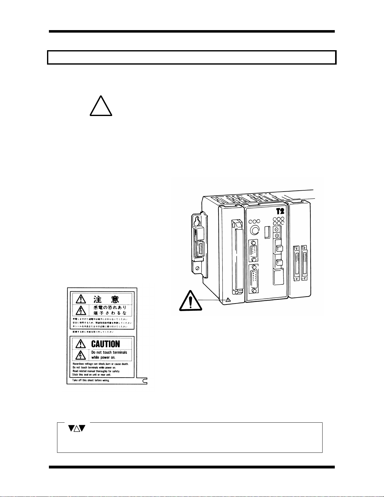
Markings used on the T2N and in this manual
Warning Mark on the T2N
This is the warning mark for dangerous location. It is attached to the equipment in
positions where there is a risk of electric shock and in positions where there is a risk
damage to the equipment through wrong wiring.
!
Take the following precautions where there is this mark.
(1) Keep hands away from terminals ,especially the input terminall of power supply while power on, to avoid
the risk of electrical shock.
(2) Turn off power before installing or removing modules, terminal blocks or wires.
(3) Applying excess power voltage to the T2N can cause explosion or fire. Apply power of the specified ratings
described in this manual.
Safety Label
The safety label as shown on the left is
attached to the power terminal of the T2N.
Remove the mount paper before wiring.
Peel off the label from the mount paper
and stick it near the power terminals
where it can be readily seen.
NOTE
This mark is printed in places in this manual which should always be read carefully.
Read them carefully.
-
vii
-
Page 9

About This Manual
NOTE
This manual has been prepared for first-time users of Toshiba’s Programmable Controller
T2N to enable a full understanding of the configuration of the equipment, and to enable the
user to obtain the maximum benefits of the equipment.
This manual introduces the T2N system configuration, and explains the specifications,
installation and wiring for T2N’s basic hardware. This manual provides the information for
designing T2N user program, such as T2N internal operation, memory configuration, I/O
allocation. Information for maintenance and troubleshooting are also provided in this
manual.
The specifications of the enhanced communication function, and how to use them, are
explained in separate manual. Read T2E/T2N User’s Manual-Enhanced communication
function. (UM-TS02E**-E003)
In addition, the T2N’s computer link function is also covered by separate manual. Read Tseries Computer Link Operation Manual for details.
Related Manuals
About This Manual
The following related manuals are available for T2N. Besides this manual, read the
following manuals for your better understanding.
T2N User’s Manual - Basic Hardware and Function - UM-TS02N**-E001
T2E/T2N User’s Manual - Enhanced communication function - UM-TS02E**-E003
TOSLINE-S20LP T2N/T3H Stations Instruction Manual -6F3B0356
Built-in Ethernet Module for T2N (PU235N/245N) Instruction Manual
T-series Instruction Set - UM-TS03***-E004
T-PDS for Windows Basic Operation Manual - UM-TS03***-E038
T-PDS Basic Operation Manual (MS-DOS) - UM-TS03***-E006
T-PDS Command Reference Manual (MS-DOS) - UM-TS03***-E007
T-PDS Ver.2.0 Expanded Functions (MS-DOS) - UM-TS03***-E028
T-Series Handy Programmer (HP911) Operation Manual - UM-TS03***-E025
T-series Computer Link Operation Manual - UM-TS03***-E008
1 Axis positioning controller Manual - UM-EX100**-E011
T2 Communication Interface Module (CF211) Manual - UM-TS02***-E013
T2/EX100 Computer Link Module (CL11) Manual - UG-TS02***-E015
TOSLINE-S20 User’s Manual - UM-TLS20**-E001
TOSLINE-F10 User’s Manual - UM-TLF10**-E001
Other than the listed above, some T2N elated manuals for special I/O modules
and data transmission modules are available. Contact Toshiba for more
information.
-6F3B0362
-
viii
-
Page 10

About This Manual
Terminology
The following is a list of abbreviations and acronyms used in this manual.
µs microsecond
ASCII American Standard Code For Information Interchange
AWG American Wire Gage
BCC Block Check Code
CCW Counter-Clockwise
CPU Central Processing Unit
CW Clockwise
EEPROM Electrically Erasable Programmable Read Only Memory
H hexadecimal (when it appears in front of an alphanumeric string)
I/O Input/Output
LED Light Emitting Diode
LSB Least Significant Bit
ms millisecond
MSB Most Significant Bit
PWM Pulse Width Modulation
RAM Random Access Memory
ROM Read Only Memory
Vac AC voltage
Vdc DC voltage
-
ix
-
Page 11

Contents
Important Information
Introduction
About This Manual
PART 1 HARDWARE
1. SYSTEM CONFIGURATION
1.1 System Configuration....................................................................................................................................................................... 3
1.2 Power Supply Module...................................................................................................................................................................... 6
1.3 CPU Module............................................................................................................................................................................................ 8
1.4 Communication Port...................................................................................................................................................................... 13
1.5 Racks......................................................................................................................................................................................................... 15
1.6 Expansion Cable.............................................................................................................................................................................. 16
1.7 I/O Modules.......................................................................................................................................................................................... 17
1.8 Data Transmission Modules.................................................................................................................................................... 18
1.9 Built-in networking............................................................................................................................................................................20
Contents
2. SPECIFICATION
2.1 General Specifications................................................................................................................................................................. 21
2.2 External Dimensions...................................................................................................................................................................... 22
2.3 I/O Module Specifications.......................................................................................................................................................... 23
3. APPLICATION PRECAUTIONS FOR I/O MODULES
3.1 Input Modules - Application Precautions....................................................................................................................... 51
3.2 DC Output Module - Application Precautions............................................................................................................ 53
3.3 Triac Output Module - Application Precautions........................................................................................................ 56
3.4 Relay Output Module - Application Precautions...................................................................................................... 56
3.5 Analog Input Module - Application Precautions....................................................................................................... 57
3.6 Analog Output Module - Application Precautions................................................................................................... 58
-
x
-
Page 12

Contents
4. INSTALLATION AND WIRING
4.1 Operating Environment................................................................................................................................................................ 59
4.2 Installing the Rack........................................................................................................................................................................... 60
4.3 Mounting the Modules.................................................................................................................................................................. 61
4.4 Connecting the Expansion Unit............................................................................................................................................. 61
4.5 Grounding.............................................................................................................................................................................................. 62
4.6 Grounding Methods........................................................................................................................................................................ 63
4.7 Wiring the Power Supply............................................................................................................................................................ 65
4.8 I/O Wiring............................................................................................................................................................................................... 66
4.9 Power up/down Sequence........................................................................................................................................................ 68
4.10 Safty Circuit....................................................................................................................................................................................... 69
5. MAINTENANCE AND CHECKS
5.1 Daily Checks........................................................................................................................................................................................ 70
5.2 Periodic Checks................................................................................................................................................................................ 72
5.3 Spare Parts to Keep in Stock................................................................................................................................................. 73
5.4 Battery Replacement..................................................................................................................................................................... 74
5.5 Fuse Replacement.......................................................................................................................................................................... 76
6. TROUBLESHOOTING
6.1 Troubleshooting Procedure...................................................................................................................................................... 77
6.2 Power Supply Check..................................................................................................................................................................... 78
6.3 CPU Check........................................................................................................................................................................................... 79
6.4 Program Check.................................................................................................................................................................................. 79
6.5 Input Check........................................................................................................................................................................................... 80
6.6 Output Check...................................................................................................................................................................................... 81
6.7 Faults Due to External Problems......................................................................................................................................... 82
6.8 List of Items for Self-Diagnostic check............................................................................................................................ 83
-
xi
-
Page 13

PART 2 FUNCTIONS
1. OVERVIEW
1.1 T2N System Configuration........................................................................................................................................................ 95
1.2 Functional Specifications........................................................................................................................................................... 97
2. INTERNAL OPERATIONS
2.1 Basic Internal Operation Flow................................................................................................................................................ 98
2.2 System Initialization........................................................................................................................................................................ 99
2.3 Mode Control.....................................................................................................................................................................................101
2.4 Scan Control...................................................................................................................................................................................... 104
2.4.1 Scan Mode........................................................................................................................................................................106
2.4.2 Batch I/O Processing................................................................................................................................................108
2.4.3 Timer Update...................................................................................................................................................................110
2.5 Peripheral Support........................................................................................................................................................................ 111
2.6 Programming Support Functions....................................................................................................................................... 112
Contents
3. USER PROGRAM RUNNING CONTROL
3.1 Program Classification............................................................................................................................................................... 115
3.2 Sub-program control....................................................................................................................................................................116
3.3 Interrupt Program control.........................................................................................................................................................116
4. PERIPHERAL MEMORY SUPPORT
4.1 EEPROM Support..........................................................................................................................................................................118
5. RAS FUNCTION
5.1 Overview............................................................................................................................................................................................... 119
5.2 Diagnostics.......................................................................................................................................................................................... 119
5.3 Event History......................................................................................................................................................................................122
5.4 Memory Protect Function.........................................................................................................................................................124
5.5 Execution State Monitoring....................................................................................................................................................125
5.6 Debug Support Function..........................................................................................................................................................127
5.7 System Diagnostics...................................................................................................................................................................... 129
-
xii
-
Page 14

Contents
PART 3 USER PROGRAMS
1. OVERVIEW
1.1 Aim of Part 3...................................................................................................................................................................................... 135
1.2 User Memory Configuration................................................................................................................................................... 135
2. USER PROGRAM CONFIGURATION
2.1 Overview............................................................................................................................................................................................... 137
2.2 System Information.......................................................................................................................................................................139
2.3 User Program....................................................................................................................................................................................142
2.3.1 Main Program.................................................................................................................................................................143
2.3.2 Sub-Program...................................................................................................................................................................144
2.3.3 Interrupt Program.........................................................................................................................................................145
2.3.4 Sub-Routines..................................................................................................................................................................146
3. USER DATA
3.1 Overview............................................................................................................................................................................................... 149
3.2 Registers and Devices............................................................................................................................................................... 152
3.3 Processing Register Data........................................................................................................................................................176
3.4 Index Modification.......................................................................................................................................................................... 183
3.5 Digit Designation.............................................................................................................................................................................186
4. I/O ALLOCATION
4.1 Overview............................................................................................................................................................................................... 189
4.2 Setting of Unit No..........................................................................................................................................................................191
4.3 Methods of Input/Output Allocation..................................................................................................................................192
4.4 Register and Module Correspondence.........................................................................................................................197
5. PROGRAM LANGUAGE
5.1 Overview............................................................................................................................................................................................... 199
5.2 Laddser Diagram............................................................................................................................................................................202
5.3 SFC...........................................................................................................................................................................................................209
5.4 Programming Precautions....................................................................................................................................................... 224
5.5 List of Instructions..........................................................................................................................................................................226
Ordering Information......................................................................................................................................................................................255
Index................................................................................................................................................................................................................................257
-
xiii
-
Page 15

Features
Networking & Communication PLC Easy to use high technology
There are three types of CPUs in the T2N.
PU215N : Standard type
PU235N : Standard type + built-in Ethernet
PU245N : Standard type + built-in Ethernet + built-in TOSLINE-S20LP
nNetworking
lEthernet connection
The T2N CPU modules (PU235N and PU245N) have built-in Ethernet interface
(10Base-T). Through the Ethernet, the T2N can communicate with higher level
controllers (computer, workstation, etc.) or other PLCs including T2N.
lTOSLINE-S20LP connection
The T2N CPU module (PU245N) has built-in TOSLINE-S20LP (Loop version)
in the CPU module. TOSLINE-S20LP is a high-reliability double-loop fiber optic network.
Features
lHigh speed industrial LAN
The T2N can be connected to Toshiba’s high speed industrial LANs (Local Area
Networks) TOSLINE-S20 and TOSLINE-F10. The TOSLINE series are suited for real
time control data linkage. Through these networks, the T2N can exchange data with
Toshiba’s various equipment, such as, DCS system, other T-series PLCs, Inverters, etc.
lDeviceNet support
A DeviceNet scanner module is available for the T2N. The DeviceNet scanner module
can read/write data to any other manufacturer’s OVDA certified devices (I/O blocks,
Inverters to include Toshiba’s G3, air manifold, sensors, etc.).
-
xiv
-
Page 16

Features
nEnhanced communication
The T2N has RS-232C/RS485 serial communication port. Either interface can be selected.
Using this port, one of the following communication functions can be used.
lComputer link mode :Connection with higher level computer, MMI/SCADA system,
modem, etc.
lData link mode :Easy data linkage between two T2Ns or T2E .
lFree ASCII mode :Active communication between serial ASCII devices. (bar code
readers, etc.).
nProgrammer port function
The T2N’s RS-232C programmer port supports the T-series computer link protocol. This
results in easy connection to a higher level computer, an operator interface unit, a modem,
etc.
n High speed processing
The T2N excels at applications where high speed processing is required.
• 0.33µs/contact • 0.44µs/coil
• 1.2µs/16-bit transfer• 1.63µs/16-bit addition
n Advanced instruction set
The T2N offers 24 basic relay-ladder instructions and 192 function block instructions,
including the following.
• Arithmetic operation • Data manipulations • Trigonometric functions
• PID/ramp/integral • Subroutine call • For-Next loop
• Averaging/filtering • ASCII↔Hex conversion • Floating-point math
n Two programming Languages
The T2N supports two programming languages: Ladder Diagram (LD) and Sequential
Function Chart (SFC). By selecting the appropriate language, or combination of the two,
program development time can be greatly reduced.
n Sufficient capacity
The T2N has 24K steps program memory and controls up to 2,048 I/O points.
-
xv
-
Page 17

PART1
HARDWARE
Page 18
1.1
(IBM compatible)
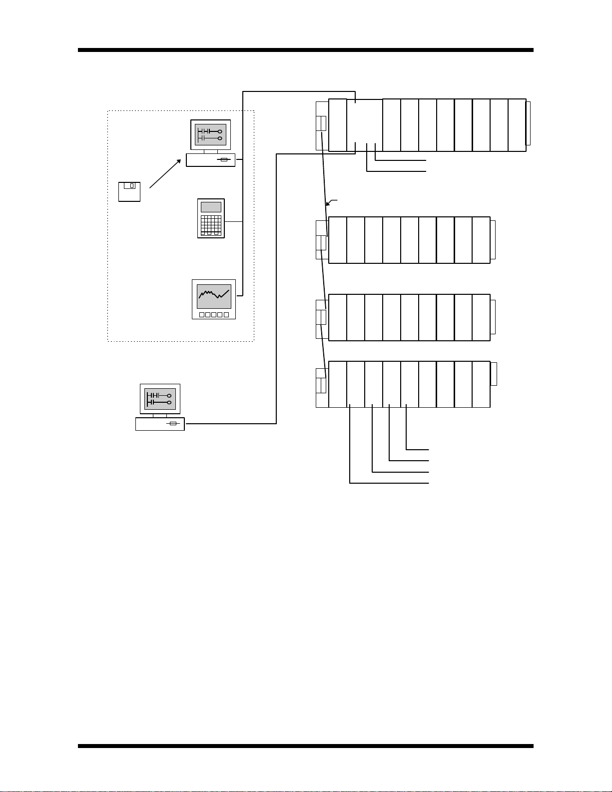
System Configuration
Peripherals
T-series Program
Development
System(T-PDS)*2
software
Handy Programmer
LCD Display etc.
Personal
Computer
HP911
1.System Configuration
Basic Unit
C
P
U
Power Supply
*1 Ethernet
*1 TOSLINE-S20LP
Expansion Cable
Expansion Unit
Power SupplyPower Supply
Expansion Unit
T
T
T
L
L
L
30
F
S
Power Supply
Personal
Computer
•Computer Link
•Serial I/F
•Data Link
(Dual T2E/T2Ns can be
communicated each other)
Up to a maximum of 3 expansion units can be connected.
Note *1: Ethernet which is built-in PU235N and PU245N
TOSLINE-S20LP which is built-in PU245N
*2: T-PDS (MS-DOS) software V2.06 or later is available for the T2N.
T-PDS (Windows) software V1.2 or later is available for the T2N.
Expansion Unit
D
N
Data transmission module
DeviceNet Scanner
TOSLINE-S20(Optic/wire)
TOSLINE-F10(wire)
TOSLINE-30(Optic/wire)
User’s manual 3
Page 19
1.System Configuration
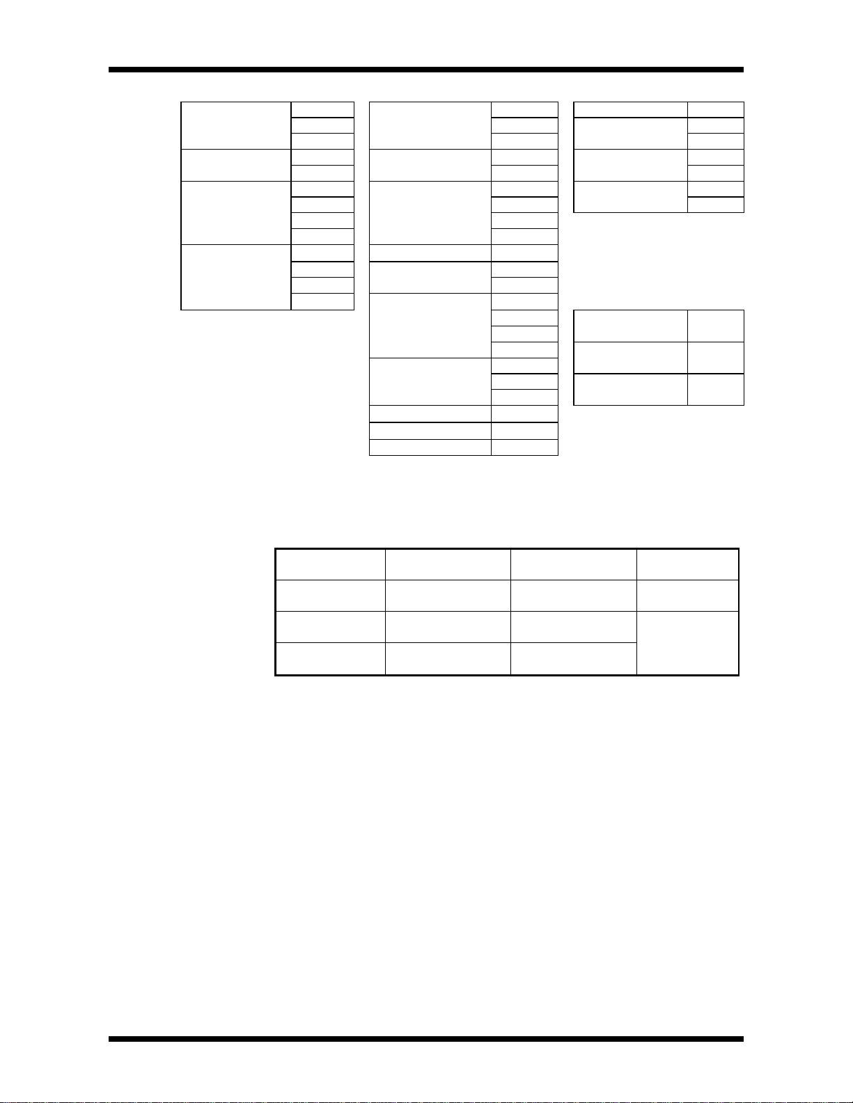
•Basic Configuration •I/O module •Data transmission Module
Rack BU268 DI32 SN221
Power Supply PS261 AC input IN51 TOSLINE-F10 MS211
Module PS31 IN61 RS211
CPU Module DO32
Expansion Cable CAR5 Relay output RO61
BU228N DC input DI31
BU266 DI235
PU215N Transistor output DO31 LK11
PU235N DO235
PU245N DO233P
CAR3 Triac output AC61
CAR7 RO62
CS2RF AI21
Analog input AI31
AI22
AI32
AO31
AO22Analog output
AO32
Pulse input PI21
Positioning module MC11
Serial interface CF211
DeviceNet scanner
TOSLINE-S20
TOSLINE-30
•Programming Tool
T-PDS
(for MS-DOS)
T-PDS
(for Windows)
Handy
Programmer
DN211
SN222A
LK12
MM33I1
MW33E1
HP911
Minimum and Maximum configuration are shown on next page.
As mentioned in Section 1.5 ,the following racks are available.
Part Number Application Number of Module
Installation
TBU228N*S Dedicated to the
Basic unit
TBU268**S For expansion unit 8
TBU266**S For expansion unit 6
8
Remarks
4 PROSEC T2N
Page 20
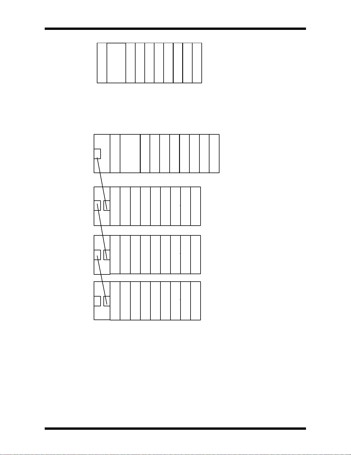
1)Minimum Configuration
/
/
/
/
/
1.System Configuration
CPU
Power Supply
Basic unit with 8 I/O modules(BU228N)
2) Maximum Configuration
I/O/I/O/I/OOI/O/I/O
Basic unit
CPU
Power Supply
Expansion Unit No.1
I/O/I/O/I/O/I/O/I/O/I/O/I/O/I/O
I/O/I/O/I/O/I/O/I/O/I/O/I/O/I/O
Power Supply
Expansion Unit No.2
I/O/I/O/I/O
Number of I/O module
8 I/O modules(BU228N)
8 I/O modules(BU268)
6 I/O modules(BU266)
8 I/O modules(BU268)
6 I/O modules(BU266)
I/O/I/O/I/O/I/O/I/O/I/O/I/O/I/O
Power Supply
Expansion Unit No.3
8 I/O modules(BU268)
6 I/O modules(BU266)
I/O/I/O/I/O/I/O/I/O/I/O/I/O/I/O
Power Supply
• Up to a maximum of 3 expansion units can be connected.
• There is no limit on combinations of the types of the rack.
• When one BU228N and three BU268 are used ,a maximum of 32 I/O modules can be
controlled by the T2N CPU.
User’s manual 5
Page 21
1.System Configuration
TOSHIBA
OUT
OUTNCNC
IN
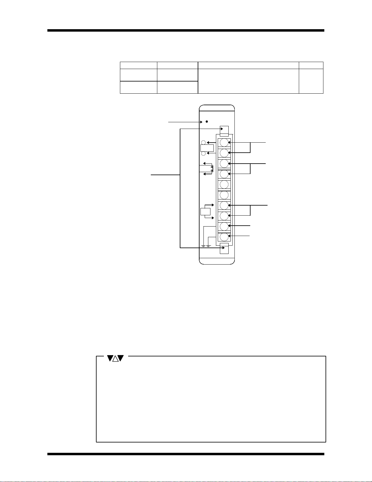
1.2
Power Supply Module Power supply modules are mounted on the left -end slots of all units. There are
two types according to the power voltage. Select one as required.
Model Power Voltage Output Rating Weight
TPS261**S 100 - 240Vac
(+10%/-15%)
EX10*MPS31 24Vdc
(+20%/-15%)
Internal 5V power supply : 2.5A (max.)
External power supply : 24V,+10%/-10%
0.5A (max.)
(Internal + external total 15W or less)
Approx.
300g
Power LED
POWER
24Vdc
+
External 24Vdc
output terminals
-
RUN
Terminal block
Run signal output
terminals
eject levers
LG
FG
L
N
Line filter ground terminal
Frame ground terminal
Power supply
terminals
• External 24Vdc Output Terminals
These terminals can be used to supply 24Vdc power to external devices such as
sensors or relay output modules. 24Vdc(±10%)-0.5A(max.)
• Run Signal Output Terminals
When the T2N is in the operating mode(RUN), built-in contact is closed.
240Vac(+10%)/24Vdc(+20%)-2A(max.)
(Can also be used on expansion units)
• Power Supply Terminals
Connect to the power supply line. (See 4.7 Wiring the power supply).
• Line Filter Ground Terminal / Frame Ground Terminal
These are grounding terminals. (See 4.6 Grounding methods).
NOTE
1. The maximum rated output of the power supply module is 15W, this includes the
internal 5Vdc and external 24Vdc output combined. Configure the system, referring to
the Module Current Consumption Table on the next page, so that the following equation
is satisfied.
15W≥5V × Total 5V current (max. 2.5A) + 24V × external 24V current (max. 0.5V)
2. Do not connect the external 24V supply terminals to the other power supply systems,
and do not run the wiring over long distances.
3. This power supply module is dedicated power supply for the T2N and T2E/T2/EX100.
Do not use it by itself for other purposes.
6 PROSEC T2N
Page 22

1.System Configuration
Module Current
Consumption Table
Name Model Internal 5Vdc External 24Vdc Weight
(approx.)
CPU PU215N 800mA or less - 300g
CPU(Ether) PU235N 1500mA or less - 400g
CPU(Ether+TOSLINE-S20LP) PU245N 2000mA or less - 400g
BU228N 50mA or less - 1600g
Rack BU268 50mA or less - 1500g
BU266 50mA or less - 1400g
16-point DC/AC input(12-24V) DI31 15mA or less - 200g
32-point DC input(24V) DI32 80mA or less - 200g
64-point DC input(24V) DI235 100mA or less - 250g
16-point AC input(100-120V) IN51 15mA or less - 250g
16-point AC input(200-240V) IN61 15mA or less - 250g
12-point relay output RO61 50mA or less DC24V, 140mA 250g
8-point isolated relay output RO62 40mA or less DC24V, 100mA 250g
16-point transistor output DO31 60mA or less DC5-24V, 35mA 200g
32-point transistor output DO32 250mA or less DC5-24V, 100mA 200g
64-point transistor output DO235 250mA or less - 250g
16-point transistor (PNP) DO233P 60mA or less - 200g
12-point triac output AC61 300mA or less - 200g
4ch analog input (8bit)
(4-20mA/1-5V)
4ch analog input (12bit)
(4-20mA/1-5V)
4ch analog input (8bit)
(0-10V)
4ch analog input (12bit)
(±10V)
2ch analog output (8bit)
(4-20mA/1-5V/0-10V)
2ch analog output (12bit)
(4-20mA/1-5V)
2ch analog output (12bit)
(±10V)
1ch pulse input PI21 80mA or less - 200g
Position control MC11 200mA or less DC12/24V, 100mA 250g
Serial Interface CF211 550mA or less - 200g
TOSLINE-30(wire) LK11 250mA or less - 200g
TOSLINE-30(optical) LK12 200mA or less - 200g
TOSLINE-S20(wire) SN221 600mA or less - 250g
TOSLINE-S20(optical) SN222A 700mA or less - 250g
TOSLINE-F10(Master Station) MS211 600mA or less - 250g
TOSLINE-F10(Remote Station) RS211 600mA or less - 250g
Devicenet scanner DN211 500mA or less - 200g
AI21 50mA or less DC12/24V, 50mA 200g
AI22 50mA or less DC24V, 50mA 200g
AI31 50mA or less DC12/24V, 50mA 200g
AI32 50mA or less DC24V, 50mA 200g
AO31 70mA or less DC24V, 90mA 200g
AO22 170mA or less DC24V, 90mA 200g
AO32 170mA or less DC24V, 90mA 200g
NOTE
The external 24Vdc in the Table are not power supplies for input/output signals.
They are the power supplies required for module operation.
User’s manual 7
Page 23
1.System Configuration
(SRUN. SONL, SACC)
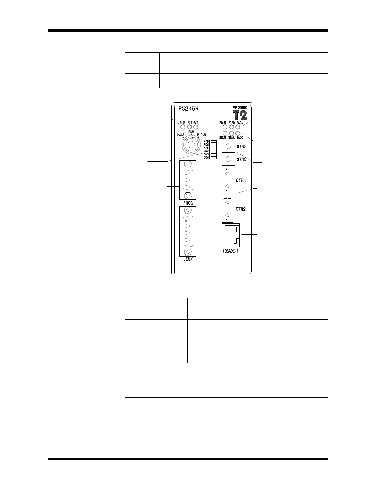
1.3 CPU Module There are three types of CPU modules with functions as shown below.
Type Specification
PU215N RAM(battery back-up) + EEPROM, User program 23.5k step,
ladder, SFC, real time clock, enhanced communication function
PU235N PU215’s function + Ethernet
PU245N PU215’s function + Ethernet + TOSLINE-S20LP
Status display LED
(RUN, FauLT, BATtery)
Operation Mode Switch
(HALT, RUN, P-RUN)
Setting Switches of
Operation Mode
Programmer port connector
(RS232C)
Communication port connector
(RS232C/RS485)
Ethernet status display
(ERUN, ET/R, EACC)
TOSLINE-S20LP status
display
Station address switches
for TOSLINE-S20LP
Communication connectors
for TOSLINE-S20LP
Communication connectors
for Ethernet
8 PROSEC T2N
Status display LEDs : Show operation states of the T2N
RUN
(Green)
FAULT
(Red)
BAT
(Green)
Status display LEDs : Show operation states of the Ethernet/TOSLINE-S20LP
For details of operation mode, see Ethernet/TOSLINE-S20LP user’s manual.
These all LED’s color is green.
ERUN Operating state (Ethernet)
ET/R Data transmission/receive state (Ethernet)
EACC T2N’s accessing state for Ethernet
SRUN Operating state (TOSLINE-S20LP)
SONL Online state of TOSLINE-S20LP
SACC T2N’s accessing state for TOSLINE-S20LP
Lit Operating state (RUN Mode)
Blink HOLD Mode
Out Stopped state (HALT Mode) or Error Mode
Lit CPU abnormal
Blink Program abnormal
Out Normal
Lit Battery normal
Blink Battery getting abnormal
Out Battery abnormal or no battery
Page 24
1.System Configuration
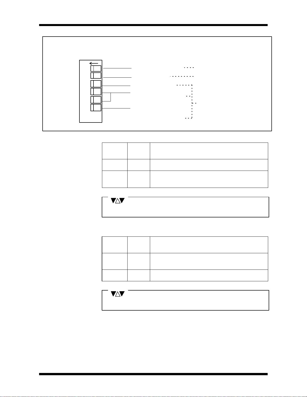
P/S
ROM
R/S
CM0
CM1
COM
• Setting Switches of Operation Mode
These switches are provided on the CPU front panel. They control the
following functions.
OFF
1
2
3
4
5
6
Programmer/S-LS Switch This switch can be changed anytime
ROM/RAM Switch CPU reads this status when power
RUN/Stand-by Switch
Selection Switch of optional
Communication function
Programmer Port
Parity
(1) Programmer/S-LS(selection) Switch
Setting
Position
SW.1
OFF T-PDS T-PDS direct connection mode : Operate as the
ON S-LS S-LS connection mode : Operate as the tool for setting
Function CPU operation
(Communication support on Programmer port)
Programmer.
parameter for TL-S20LP.Or operate as the remote
programmer T-PDS via TL-S20LP.
is changed from OFF to ON or when
operation mode is changed to RUN.
CPU reads these switches status
only when power turns to ON.
NOTE
Programmer/S-LS (selection) switch is set to Programmer at the factory.
(2) ROM/RAM Switch
Setting
Position
SW.2
OFF ROM Starts up after the content of the EEPROM has been
ON RAM Starts up on the content of the RAM.
Function
CPU operation
at power up and at the beginning of the RUN mode
transferred to the RAM.
(Transfer is not executed when P-RUN is selected.)
(No program transfer)
NOTE
The ROM/RAM switch is set to ROM at the factory.
User’s Manual 9
Page 25

1.System Configuration
(3) RUN/Stand-by Switch
The RUN/Stand-by switch is set to RUN at the factory.
(4)(5)Selection Switch of optional Communication function
Setting Position Operation
Setting
Position
SW.3
Function Operation
Mode
Switch
HALT HALTOFF Automatic
RUN
RUN RUN Automatic RUN start occurs.
HALTON Stand-by
RUN
Mode after
power up
HALT
Remarks
Starts up in HALT mode. Ready
to start operation by RUN command from the programmer or by
shifting the operation mode
switch.(→HALT→RUN)
NOTE
Function
SW.4 SW.5
OFF OFF Computer Link The T2N can communicate with a master
computer using T-series computer link
protocol.
ON OFF Data Link The T2N executes data link with other T2N.
OFF ON Free ASCII The T2N can communicate with external
devices using ASCII code.
ON ON Reserved No operation.
NOTE
1. These switches are set to computer link function at the factory.
2. For details of the operation mode, see Section 1.4.
(6)Programmer Port Parity
Setting
Position
SW.6
OFF Odd Parity 8 bit Data, 9600bps, Data length is 11bit.
ON No Parity 8 bit Data, 9600bps, Data length is 10bit.
Function Remarks
NOTE
The Programmer Port Parity switch is set to Odd Parity at the factory.
The T2N can connect to Modem by using this switch.
Control signals (CTS,DTR,etc) should be set to No Use at the modem side.
Response of the T2N can be delayed on the programmer port using SW38
(Programmer port response delay mode register).
10 PROSEC T2N
Page 26
1.System Configuration
• Operation Mode Switch
The Operation Mode Switch is provided on the CPU module.
This switch controls T2N operation (RUN/P-RUN/HALT).
Stop user program execution (HALT mode)
HALT
CPU status is shown below after power up or after the operation mode is
changed to RUN from HALT.
Setting
Position
P-RUN
User
Program
Executed RUN
Operation
RUN
Start user program execution (RUN mode)
Mode
Initial Load
Program
exe : executed
- :not executed
SW.2:OFF exeHALT Stopped HALT
SW.2:ON SW.2:OFF exeRUN
SW.2:ON SW.2:OFFP-RUN
SW.2:ON
- protect
Memory
Protection
No protect not available
No protect
Operation
Mode Change
programmer
available
by the
As shown the above table, initial load (program transfer into EEPROM from RAM)
performs in the RUN mode when setting SW.2 to OFF except P-RUN position.
NOTE
1. The operation mode switch is set to HALT at the factory.
2. “P-RUN” is state that the operation mode switch set to P-RUN.
The user program and the first half of data register (D0000 to D2047) are
in the write protect mode and user can’t write or change them.
3. Normally, the programming is carried out in the HALT mode.
4. When shifting to the RUN mode with the ROM/RAM switch in the ROM
position , operation will commerce after program transfer has been
executed. (that is, it is called initial load.)
5. For details of the operation mode, see Part2, Section 2.3.
6. When the operation mode switch is changed quickly from HALT to P-RUN,
program transfer is interrupted.
Turn to P-RUN after the RUN LED is lit.
7. The RAM is backed up by battery of the T2N. When the battery voltage
drops and the T2N can’t keep retentive area in the RAM, CPU clears all the
retentive data.
Then CPU checks user program BCC. If error is detected, CPU registered
error.
User’s Manual 11
Page 27

1.System Configuration
• Programmer Port
The programmer (T-PDS or HP911) is connected to this programmer port.
Connector type of CPU side is female , 9-pin D-SUB connector.
The T2N’s RS232C programmer port can accept the computer link protocol
(data read/write). This results in easy connection to a higher level computer,
an operator interface unit, etc. directly.
General specifications and the connector pin assignment of programmer port
are shown below.
For details of T-series computer link protocol, see T-series User’s manual
- Computer Link (UM-TS03***-E008).
Communication specifications
Item Specifications
Interface Conforms to RS232C
Configuration One to One
Transmission distance 15m max.
Transmission speed 9600bps (fixed)
Frame format Start bit 1bit
Data 8bit
Parity odd/none (selected by SW.6)
stop bit 1bit
Supported command DR (Data Read)
DW (Data Write)
ST (Status read)
Pin assignment of programmer port
Signals No. of pins Symbols Direction
Transmission data 3 TXD
Receive data 2 RXD
Signal ground 5 SG T2N -- Host
Request To Send 7 RTS
Clear To Send 8 CTS
T2N → Host
T2N ← Host
T2N → Host
T2N ← Host
NOTE
Other pins except the above table should not be connected.
12 PROSEC T2N
Page 28
1.4
Communication port
1.System Configuration
The T2N supports enhanced communication functions. Either RS485 or
RS232C can be selected for this communication port by using selection
switches.
There are three communication functions in the T2N.
One of them can be selected by setting swithches CM0/CM1 (SW.4/SW.5).
Function Operation
Computer Link This performs to connect between a Host computer and
up to 32 T2Ns, using RS485.
(one to one ,using RS232C)
Data Link This performs to connect two T2E/T2Ns.
They share 32W data with each other.
Free ASCII This performs to connect between the external devices
such as inverter, etc. and the T2N.
For details of these functions and usage method, see T2E/T2N User’s manual
- Enhanced communication function -(UM-TS02E**-E003).
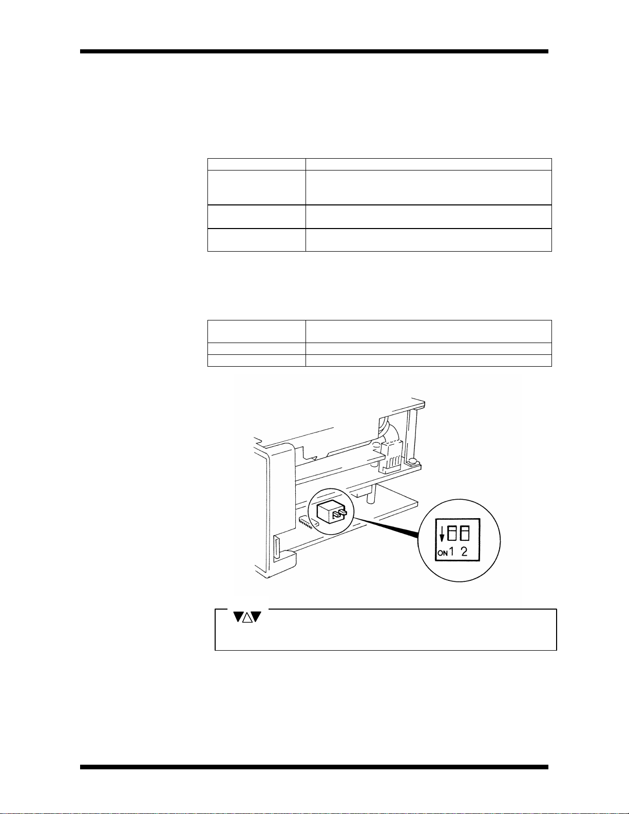
• Switch settinf of communication port.
Setting Position
Dip-SW.1
OFF Conforms to RS485.
ON Conforms to RS232C.
Communication port interface.
NOTE
These swithes are set to RS485 at the factory.
User’s Manual 13
Page 29

1.System Configuration
• Pin assignment of communication port (LINK).
Transmission data 5 TXD RS232C
Receive data 12 RXD RS232C
Request To Send 6 RTS RS232C
Clear To Send 14 CTS RS232C
Signal Ground 7,8,15 SG RS232C/485 T2N - Host
Transmission data A 3 TXA RS485
Transmission data B 11 TXB RS485
Receive data A 2 RXA RS485
Receive data B 10 RXB RS485
No Connection 1,4,9,13 NC
Signals No. of pins Symbols Interface Direction
T2N→Host
T2N←Host
T2N→Host
T2N←Host
T2N→Host
T2N→Host
T2N←Host
T2N←Host
D-SUB 15pin connector.
15
8
9
1
14 PROSEC T2N
Page 30
1.System Configuration
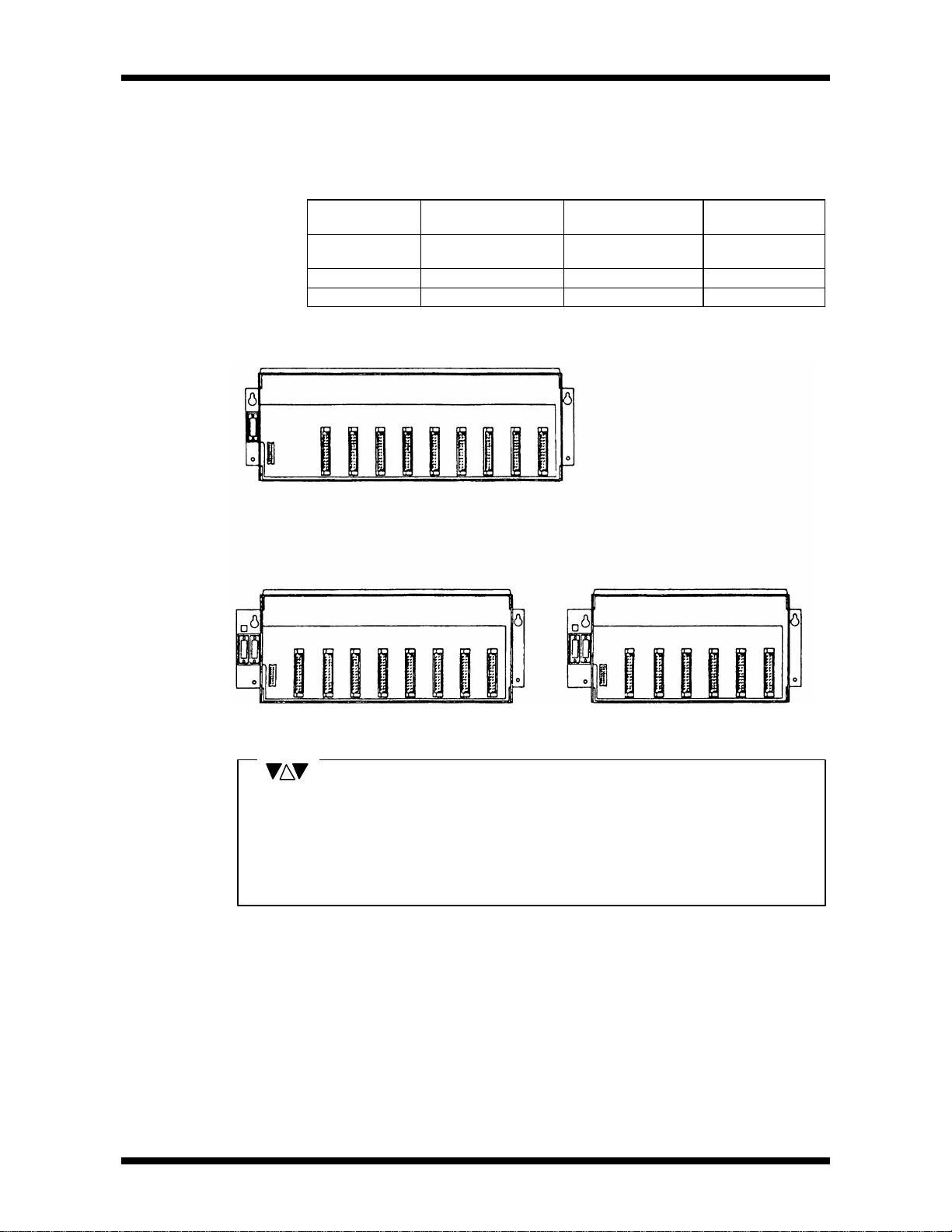
1.5 Racks As mentioned in Section 1.1, the rack is available in the three types as follows.
The BU228N is for the basic unit, and the BU268/BU266 are for the expansion
unit.
BU228N
Type Application Number of Module
Installation
BU228N Dedicated to the
Basic unit
BU268 For expansion unit 8
BU266 For expansion unit 6
8
BU266BU268
Remarks
NOTE
1. Two expansion connectors are provided in the BU268 and the BU266. The right side
connector is for connecting the basic unit/previous expansion unit.
The left side connector is for connecting the next expansion unit.
2. Use a blind slot cover (EX10*ABP1) to prevent debris from entering in the rack
where no I/O modules is mounted .
User’s Manual 15
Page 31

1.System Configuration
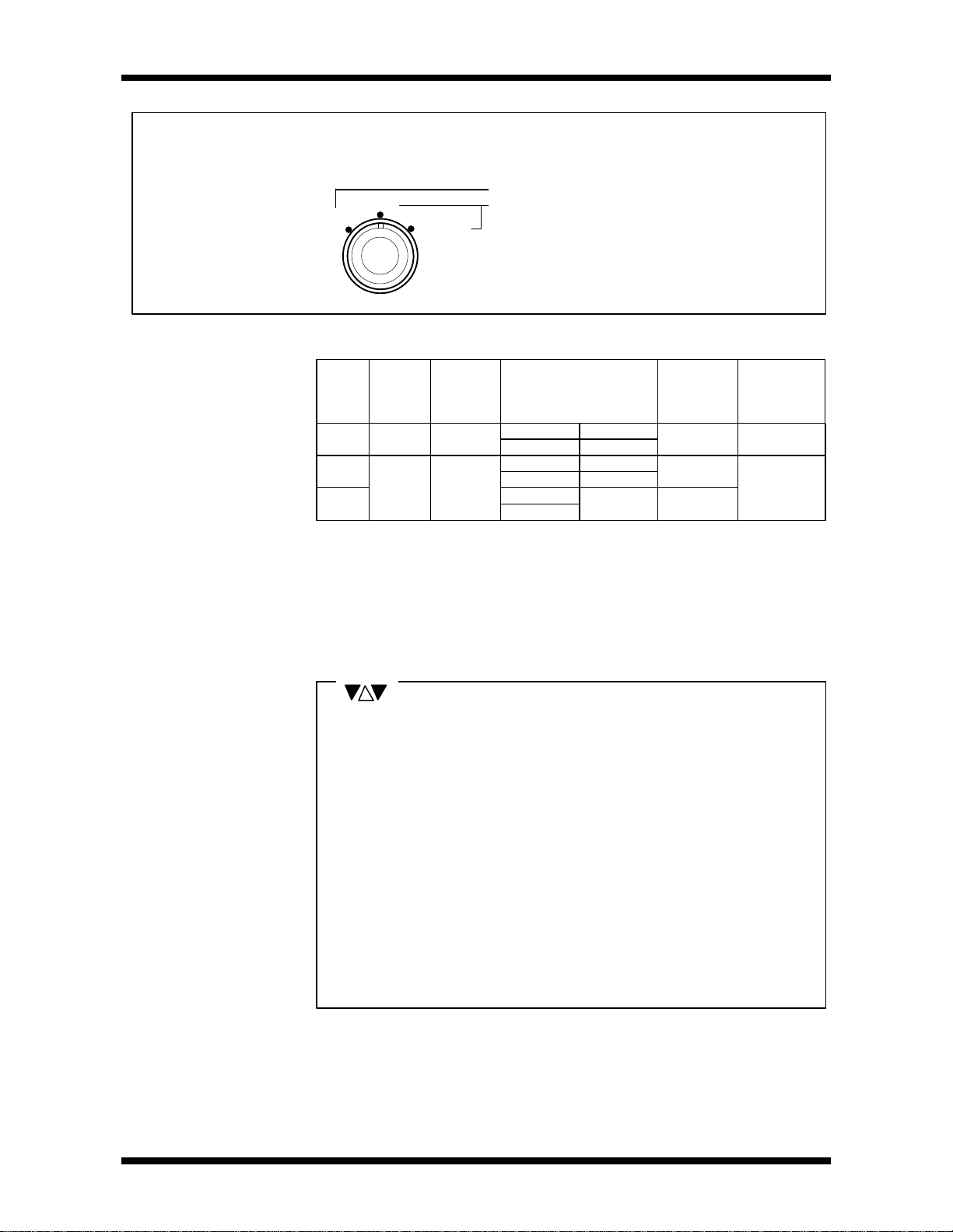
• Setting the Unit No.
When using the BU268 or the BU266 for dedicated expansion units,
set the Unit No. before operating. The setting is carried out by a rotary switch
in the upper part of the expansion connector on the left hand side of the rack.
NOTE
The rack used for : Switch Setting
Expansion Units Set in the order 1>2>3, starting from the
unit closest to the basic unit
1. Switches will be set at 0 at the factory.
2. Be careful not to duplicate Unit Nos. on units.
3. Do not use setting 4 - 9, as these are not for use.
1.6
Expansion Cables These are used for connecting the basic unit and the expansion units.
They are available in the following four lengths.
Type Length
CAR3 30cm
CAR5 50cm
CAR7 70cm
CS2RF 1.5m
NOTE
The maximum cable length between units is 1.5m.
The maximum total cable length is 4.5m.
16 PROSEC T2N
Page 32

1.System Configuration
1.7
I/O Modules Various types of I/O modules are available for the T2N, as shown in the
following table. Thus, it can respond to a wide variety of applications.
I/O modules can be mounted in any slot in the rack, and in any order.
(See Section 4.8 for recommended arrangements)
Input/Output status
display LEDs
Terminal block
eject levers
Type Description Specification
DI31 DC/AC input 16-point (16 points per common),12-24V dc/ac
DI32 DC input 32-point (8 points per common),24Vdc
DI235 DC input 64-point (8 points per common),24Vdc
IN51 16-point (16 points per common),100-120Vac
IN61
RO61 12-point (4 points per common),
RO62
DO31 16-point (16 points per common),5-24Vdc
DO32 32-point (8 points per common),5-24Vdc
DO235 64-point (8 points per common),5-24Vdc
DO233P
AC61 Triac output 12-point (4 points per common),100-240Vac
AI21 4-channel (not isolated between channels),
AI31
AI22 4-channel (not isolated between channels),
AI32
AC input
Relay output
Transistor output
Analog input
(8bit)
Analog input
(12bit)
16-point (16 points per common),200-240Vac
240Vac(+10%)/DC24V(+20%),
2A/point,4A/4 points common (max.)
8-point (each point isolated),
240Vac(+10%)/DC24V(+20%), 2A/point (max.)
1A/point, 1.2A/4 points (max.)
0.1A/point, 0.8A/8 points common (max.)
0.1A/point, 0.8A/8 points common (max.)
16-point (16 points per common),12-24Vdc
0.5A/point, 0.6A/2-element SSR (max.)
1-5V/4-20mA, 8bit resolution
4-channel (not isolated between channels),
0-10V ,8bit resolution
1-5V/4-20mA, 12bit resolution
4-channel (not isolated between channels),
-10V - +10V ,12bit resolution
Input/Output terminal block
(10-pin/18-pin)
User’s Manual 17
Page 33

1.System Configuration
Type Description Specification
AO31 Analog output
(8bit)
AO22 4-channel (not isolated between channels),
Analog output
AO32
PI21 Pulse input 1-channel (two phase, with zero marker),
MC11 Single-axis
CF211 Serial Interface RS-232C 1port,
(12bit)
positioning
NOTE
For detailed specifications of each I/O module, see Section 2.3 I/O Module
Specifications.
1.8
Data Transmission By applying the following 4 types of data transmission module according to the
Module system requirements, the T2N can configure the flexible and efficient control
systems.
2-channel (not isolated between channels),
1-5V/0-10V/4-20mA, 8bit resolution
4-20mA /1-5V,12bit resolution
4-channel (not isolated between channels),
-10V - +10V,12bit resolution
5/12Vdc, 100kpps (max), 24bit counter
1 axis, 100kpps(max.), position data memory
capacity 64 points
Common memory 160W×2
• TOSLINE-F10
PLC to PLC data linkage and remote I/O systems are configured by the
TOSLINE-F10 data transmission equipment.
Up to 8 T2 stations can be mounted in any slots, in the same way as I/O modules.
MS211/RS211
(High-speed setting)
Topology Bus (twisted-pair cable)
Transmission speed 750kbps 250kbps
Transmission Distance 500m 1km
Number of stations max. 32stations
Transmission capacity 32 words (L/LW)
Response speed 7ms(when 32 words) 12ms(when 32 words)
MS211/RS211
(Long-distance setting)
18 PROSEC T2N
Page 34

1.System Configuration
• TOSLINE-S20
The TOSLINE-S20 is a Local Area Network (LAN) for factory automation systems.
It can achieve high-speed data linkage between PLCs and communication between
industrial computers.
One T2 station can be mounted in any slot, in the same way as an I/O module.
SN221 and SN222A are allocated as optional card in the T2N.
Therefore READ/WRITE instructions should be used to access data of TOSLINE-S20
modules, because the link registers are not assigned.
SN221
(Co-Axial Cable)
Topology Bus
Transmission speed 2 Mbps
Transmission Distance 1km 10km
(1km between stations)
Number of stations Max. 64 stations
Response speed Minimum 5ms in scan transmission
• TOSLINE-30
The T2N can use the TOSLINE-30.
It is effective when connecting EX series systems to the T2N.
Up to 4 T2 stations can be mounted in any slots, in the same way as I/O modules.
The link relay/register(Z/W) is assigned for the TOSLINE-30, the same as the
TOSLINE-S20LP. If the TOSLINE-S20LP is used together with the TOSLINE-30,
the link registers assigned to the TOSLINE-30 (starting with W0000) should not
allocate for the TOSLINE-S20LP.
LK11
(Twisted-pair Cable)
Topology Bus Star
Transmission speed 187.5kbps 375kbps
Transmission Distance 1km 2km
Number of stations MAX. 17 stations MAX. 16 stations
Transmission capacity 8/16/32 words W0000-W0127
SN222A
(Optical Fiber Cable)
LK12
(Optical Fiber Cable)
(1km between stations)
Response speed 25ms(when 32words) 19.2ms(when 32words)
• DeviceNet (Scanner)
The DeviceNet is a field network. It can achieve data linkage between the T2N and
any ODVA certified devices.
The T2N can use the DeviceNet scanner module.
It is effective for connecting DeviceNet systems to the T2N.
The T2N stations can be mounted in any slots, in the same way as for I/O
modules.
DN211
(Twisted-pair Cable)
Topology Bus
Transmission speed 125kHz 250kHz 500kHz
Transmission Distance 500m 250m 100m
Number of stations Max. 64 stations
User’s Manual 19
Page 35

1.System Configuration
1.9
Built-in networking The T2N has built-in networking as follows.
Type TOSLINE-S20LP Ethernet
PU215N - PU235N - Built-in
PU245N Built-in Built-in
For details of networking, see the following manuals.
Ethernet Built-in Ethernet Module for T2N (PU235N/245N)
Instruction Manual 6F3B0362
TOSLINE-S20LP TOSLINE-S20LP T2N / T3H Stations
Instruction Manual 6F3B0356
• Ethernet
The Ethernet is a standard Local Area Network (LAN) not only for OA but also for
factory automation systems.
It can achieve high-speed data linkage between PLCs and communication with
higher level computers (workstation/personal computer). The T2N supports T-series
computer link function, PLC data link function and socket interface function.
The T2N has 10BASE-T interface for the Ethernet.
Topology Bus
Transmission speed 10Mbps
between nodes 200m(one HUB) 1700m(four HUBs)Transmission
Distance
Number of nodes Max. 1 node/1 segment
Communication Function (2) T-series PLC link
between segments 100m
(1) T-series computer link
(3) Socket interface
Specifications
• TOSLINE-S20LP
The TOSLINE-S20LP is a Local Area Network (LAN).
It can achieve high-speed data linkage between PLCs.
The TOSLINE-S20LP is a double-loop system using optical fibers and can
continue data linkage if any problem is occured in one loop.
Transmission data capacity is expanded to 4k words.
Specifications
Topology Double-Loop
Transmission speed 2Mbps
between stations 1km (4km using the optical repeater)Transmission
Distance
Number of stations Max. 64 stations/loop
Transmission capacity 4,096words
Response speed Min. 5ms in scan transmission
total 30km
W0000-W2047 (Z/W) and any 2048word
registers (using XFER instruction)
(1) Scan transmissionCommunication Function
(2) Message transmission
20 PROSEC T2N
Page 36

2.1
General Specification
2.Specification
Item Specification Remarks
Rated Voltage (1)100-240Vac PS261
(2)24Vdc PS31
(1)85 - 264Vac PS261Voltage
Fluctuation
Range
Power Supply
Frequency
Frequency
Fluctuation
Range
Retentive
power
Power Supply
interruption
Power
consumption
Inrush current (1) 15A(at 100Vac) or less
Insulation
resistance
Withstand voltage 1500Vac - 1minute *1
temperature
Ambient humidity
Atmosphere No corrosive gases
Dust 10mg/m
Vibration immunity 16.7Hz-3mm p-p
Shock immunity 98m/s2 (10g) (3 shocks per axis, on 3
Noise immunity
Grounding
Construction Installed in control panel
Cooling Natural air cooling
Notes *1 Insulated Circuits
• between Power supply circuit and I/O circuit
• between Accessible metal parts and Power supply circuit
• between Accessible metal parts and I/O circuit
• between SELV circuit and Power supply
• between SELV circuit and I/O circuit
(2)20.4 - 28.8Vdc PS31
(1)50/60Hz
(1)47 - 63Hz
10ms or less
(at maximum load for one power supply
module)
(1)53VA or less PS261
(2)22W or less PS31
35A(at 240Vac) or less
(2)30A/10ms or less PS31
10MΩor more
(between power terminals and
ground terminals)
0 to 55°C
-20 to 75°C
20∼90%RH no condensation
Sulphurous acid gas 0.05ppm or less
Hydrogen sulphide 0.01ppm or less
(3 mutually perpendicular awes)
mutually perpendicular awes)
1000Vp-p /1µs
Complied for EMC Directive of CE marking
Grounding resistance 100Ω or less
3
or less
PS261
operationAmbient
storage
Accessible metal parts: Racks, Protective ground terminal, etc.
SELV (Safety Extra Low Voltage) circuit: Internal logic circuit
The accessible metal parts of the peripherals which are connected
to the programmable controller by the standard cable are
connected to the Protective ground terminal, or double insulated.
User’s manual 21
Page 37

2.Specification
External dimensions
Basic dedicated unit (BU228N)
Expansion unit (BU266) Eexpansion unit (BU268)
2.2
When 16-point I/O module installed
When 32/64-point I/O, MC11 installed
22 PROSEC T2N
Page 38

2.3
Circuit Configuration
........
........
CO
2
0
1
F
N
H
LED Display
COM
COM
COM
I/O Module
Specifications
16-point DC/AC input
D I 3 1
0 1 2 3 4 5 6 7
8 9 A B C D E F
0
1
2
3
4
5
6
7
8
9
A
B
C
D
E
F
2.Specification
Item
%
Input Voltage Range
12 - 24V
+ 10
dc/ac(50/60Hz)
%
− 15
Minimum ON Voltage 9.6V or more
Maximum OFF Voltage 3.6V or less (leak current 0.7mA or less)
Input Current(Type) Approx.8mA (at 24Vdc)
No. of input point 16 points/common
N Mode 10ms or less (dc) / 20ms or less (ac)ON Delay
H Mode 1.5ms or less (dc)
N Mode 10ms or less (dc) / 15ms or less (ac)OFF Delay
H Mode 1.5ms or less (dc)
Withstand Voltage 1500Vac / 1minute
Current Consumption 15mA (5Vdc) or less
Weight Approx. 200g
DI31
(EX10*MDI31)
* Filter
Selection
12-24Vac/dc IN
Terminal Connections
Internal Circuit
* Filter Selection(jumper plug setting)
N ; Standard DC/AC common use(set at the factory)
H ; High-speed DC input only
0
1
3
5
7
9
B
D
2
4
6
8
A
C
E
F
12-24V
User’s manual 23
Page 39

2.Specification
CN1(XWn)
CN2(XWn+1)
1
12121
CN2
CN1
A B
B A
32-point DC input
D I 3 2
CN1
0 1 2 3 4 5 6 7
8 9 A B C D E F
0 1 2 3 4 5 6 7
8 9 A B C D E F
CN2
24Vdc IN
Item
Input Voltage Range
Minimum ON Voltage
Maximum OFF Voltage
Input Current
Number of Input point
ON Delay
OFF Delay
N Mode
H Mode 1.5msec or less
N Mode
H Mode 1.5msec or less
24Vdc ± 10% - 15%
18.0V
6.0V
Approx 5mA(at 24Vdc)
32points
10msec or less
10msec or less
(EX10*MD132)
External Connections 2 x 24pin connectors
Number of commons 4
Common
Configuration
Number of Input points
per Common
8 points
Common Polarity No Polarity
Withstand voltage 1500Vac / 1 minute
Current Consumption 80mA (5Vdc) or less
Weight Approx. 200 g
Circuit Configuration
0
1
7
COM
Internal circuit
LED display
Selection of the filter constant can be set in
16-point units (CN1, CN2) by DIP switch
setting. (set on N mode at the factory)
Switch
OFF ON Application
No.
1 N mode H mode CN1(XWn)
2 N mode H mode CN1(XWn+1)
Terminal Connections
+
B A
COMlNC
12 12
F
11 11
D
10 10
B
9 9
9
8 8
NC
7 7
NC
6 6
NC
5 5
7
4 4
5
3 3
3
2 2
1
1 1
E
C
A
8
NC
NC
COM0
6
4
2
0
+
+
+
+
DI32
+
+
COM2
+
COM3
+
A B
1
0
1 1
2
3
2 2
4
5
3 3
7
6
4 4
NC
5 5
NC
NC
NC
6 6
NC
7 7
9
8
8 8
B
A
9 9
D
C
10 10
E
F
11 11
12 12
NC
NOTE
Connectors on the Module: FCN-365P024-AU (made by Fujitsu)
Cable side connectors:
Soldering type (standard attached)
Connector FCN-361J024-AU (made by Fujitsu)
Connector cover FCN-360C024-E (made by Fujitsu)
24 PROSEC T2N
Page 40

2.Specification
CN2
CN1
64-point DC input.
Item DI235
Input Voltage Range
24Vdc
− 15
%
%
+ 10
Input Current Apporx.4mA(at 24Vdc)
Input Impedance
5.8kΩ(24Vdc)
Minimum ON Voltage 16V
Maximum OFF Voltage 5V
ON delay 10ms or less than
OFF delay 15ms or less than
External Connections
2 × 40 pin connectors
Number of Commons 8
Common
Configuration
Number of Input
Points per Common
8 points
Common Polarity No Polarity
Derating Condition See next page
Current Consumption 100mA (5Vdc) or less
Withstand voltage 1500Vac/ 1 minute
Weight Approx. 250g
Circuit Configuration
0L
7L
LC0
8L
LC1
0H
HC0
8H
HC1
0L
LC0
8L
LC1
0H
HC0
8H
HC1
LED
∼
display
Internal Circuit
User’s manual 25
Page 41

2.Specification
NC
NC
PS
FL
FH
PS
0H
0L
FL
A B
B A
L
H
PSPSPS
PS
PSPSPS
H
L
Terminal Connections
CN1
(B)(A)
20 20
NC
19 19
HC1
18 18
17 17
EH
16 16
DH
15 15
CH
14 14
BH
13 13
AH
12 12
9H
11 11
8H
10 10
HC0
9 9
7H
8 8
6H
7 7
5H
6 6
4H
5 5
3H
4 4
2H
3 3
1H
2 2
0H
1 1
NC
LC1
EL
DL
CL
BL
AL
9L
8L
LC0
7L
6L
5L
4L
3L
2L
1L
0L
1L
2L
3L
4L
5L
6L
7L
LC0
8L
9L
AL
BL
CL
DL
EL
LC1
NC
NC
CN2
(A)(B)
1 1
2 2
3 3
4 4
5 5
6 6
7 7
8 8
9 9
10 10
11 11
12 12
13 13
14 14
15 15
16 16
17 17
18 18
19 19
20 20
1H
2H
3H
4H
5H
6H
7H
HC0
8H
9H
AH
BH
CH
DH
EH
FH
HC1
NC
NC
CN2
CN1
CN1-L=XWn
CN1-H=XWn+1
CN2-L=XWn+2
CN2-H=XWn+3
20
1
20
1
: Power Supply
24Vdc
Connectors on the Module : FCN-365P040/AU (made by Fujitsu)
Cable side connectors : Soldering type (standard attached)
Connector : FCN-361J040-AU (made by Fujitsu)
Connector cover : FCN-360C040-E (made by Fujitsu)
Derating Condition
Number of input ON points (per 1 conncctor)
32 (100%)
26 (80%)
20 (60%)
0 10 20 30 40 50 60
21.6Vdc or less
24Vdc
26.4Vdc
Ambient temperature
26 PROSEC T2N
Page 42

2.Specification
201
F
COM
COM
COM
........
........
*
16-point AC input
IN51
0 1 2 3 4 5 6 7
8 9 A B C D E F
0
1
2
3
4
5
6
7
8
9
A
B
C
D
E
F
100-120Vac IN
Item
Input Voltage Range
(Sine wave)
Minimum ON voltage
(Sine wave)
Maximum OFF voltage
(Sine wave)
IN51
(EX10*MIN51)
100-120Vac + 10%
(50/60Hz)
-
15%
200-240Vac + 10%
(50/60Hz)
80Vac or more 160Vac or more
30Vac or less
(leak current 2mA or less)
60Vac or less
(leak current 2mA or less)
IN61
(EX10*MIN61)
-
15%
Input Current(Sine wave) Approx 7mA (100V-50Hz) Approx 6mA (200V-50Hz)
Number of Input Points 16 points (single common)
16 points (single common)
ON Delay (Sine wave) 20mS or less 20mS or less
OFF Delay (Sine wave)
15mS or less 15mS or less
Voltage lnsulation 1500Vac / 1 minute 1500Vac / 1 minute
Current Consumption 15mA (5Vdc) or less 15mA (5Vdc) or less
Weight Approx 250g Approx 250g
Circuit Configuration
Intermal
circuit
LED
indication
Terminal connections
1
3
5
7
9
B
D
2
4
6
8
A
C
E
F
COM
0
*
IN51 : 100-120Vac (50/60HZ)
IN61 : 200-240Vac (50/60HZ)
User’s manual 27
Page 43

2.Specification
1.ON/OFF life of relays: Electrical 100,000 times
display
CI
NC
C2
C3
COIL
........
....
12-point Relay Output
RO61
0 1 2 3 4 5 6 7
8 9 A B
0
1
2
3
4
5
6
7
+
8
9
A
B
-
24Vd
RELAY OUT
Item
RO61
(EX10*MRO61)
Load voltage 24Vdc, +20%(MAX)/240Vac, + 10%(MAX)
Maximum load 2A/point (resistive load), 1A/point (inductive load), 4A/4points
common
Minmum load 50mW (5V or more)
Number of output points 12 points (4 points / common)
ON delay 10ms or less
OFF delay 15ms or less
Leakage current When OFF 0mA
Withstand voltage 1500Vac / 1 minute
Current consumption 50mA (5Vdc) or less
External relay Coil
Power required
24Vdc +/- 10% - 140mA/all points ON (10mA/point)
Weight Approx 250g
Circuit Configuration
Internal
circuit
LED
1
2
3
C
4
7
C
8
B
C
Terminal Connections
28 PROSEC T2N
1
3
2
C1
4
0
24V
5
7
+
9
B
-
6
C2
8
A
C3
NOTE
Mechanical 20 million times
2.No overload protection fuses are built into this module.Therefore
connect fuses externally suitable to the current capacity.
Page 44

2.Specification
........
8-point Isolated
Relay Output
RO62
0 1 2 3 4 5 6 7
0
1
2
3
4
5
6
7
24V
dc
RELAY OUT
Item
RO62
(EX10*MRO62)
Load voltage 24Vdc, +20%(MAX)/240Vac, +10%(MAX)
Maximum load 2A/point (resistive load), 1A/point (inductive load)
Minimum load 50mW (5V or more)
Number of output points 8 points (each point isolated)
ON Delay 10msec or less
OFF Delay 15msec or less
Leakage current When OFF 0mA
Voltage insulation 1500Vac / 1 minute
Current consumption 40mA (5Vdc) or less
External Relay Coil Power
Required
24Vdc +/- 10% - 100mA/all points ON
(10mA/point)
Weight Approx 250g
Circuit Configuration
LED display
0
1
2
Terminal Connections
NOTE
Internal Circuit
0
1
2
3
4
5
6
7
24Vdc
1. ON/OFF life of relays: Electrical 100,000 times
Mechanical 20 million time
2. No overload protection fuses are built into this module. Therefore
connect fuses externally suitable to the current capacity.
User’s manual 29
Page 45

2.Specification
........
........
16-point Transistor Output
DO31
0 1 2 3 4 5 6 7
8 9 A B C D E F
0
1
2
3
4
5
6
7
8
9
A
B
C
D
E
F
+
-
5-24Vdc OUT
Item
DO31
(EX10*MDO31)
Load power supply 5-24Vdc+10%/-5% (Internal current consumption 35mA or less)
1A/point (external power supply 7V or more)
0. 3A/point (external power supply less than 7V)
Output ON current
Output ON resistance
1.2A/4 points (4-element transistor array)
1.5Ω or less
Number of output points 16 points (single minus common)
On Delay 1ms or less
OFF Delay 1ms or less
Leak current when Output
0.1mA or less
OFF
Voltage insulation 1500Vac/ 1 minute
Current consumption 60mA (5Vdc) or less
Weight Approx 200g
Circuit Configuration
LED display
Transistor array
Constant voltage circuit
Terminal Connections
0
1
2
3
4
8
C
F
Fuse
+
- Common
(5A)
0
1
3
5
7
9
B
D
F
-
2
4
6
8
A
C
E
+
5 - 24Vdc
30 PROSEC T2N
Page 46

2.Specification
5-24Vdc OUT
12
1
CN2
A B
1
12
CN1
B A
Vin
Vin
+6426
402BVin
COM1
COM0
Vin
BA12121111101099887766554433221
1
1
3
57NC
9
B
ADFNCNC
CED
F9B
AB1122334455667788991010111112
12
E
CA8
NCNCNC
COM2
NC
CN2(Ywn+1)
CN1(YWn)
+10753+
+
32-point Transistor Output
DO32
CN1
0 1 2 3 4 5 6 7
8 9 A B C D E F
0 1 2 3 4 5 6 7
8 9 A B C D E F
CN2
Item
DO32
(EX10*MDO32)
Load voltage 5-24Vdc +10%/-5%
100mA/point (when load voltage 24V)
Output ON current
20mA/point (when load voltage 5V)
800mA/common
Saturation voltage when ON 0.4V or less
Number of output points 32 points
Output type Current sinking
ON Delay 1msec or less
OFF Delay 2msec or less
Leakage current When OFF 0.1mA or less
External connections 2 x 24 pin connectors
Number of Common 4
configuration
Number of output points
per common
8 pointsCommon
Common polarity minus common
Withstand voltage 1500Vac / 1 minute
Current consumption 250mA (5Vdc) or less
Built-in fuse 2A/common x 4
Weight Approx 250g
Circuit Configuration
LED display
Internal Circuit
Vin
0
1
7
COM
2A
Terminal Connections
COM3
NOTE
Connectors on the Module : FCN-365P024-AU (made by Fujitsu)
Cable side connectors
Soldering type (standard attached)
Connector : FCN-361J024-AU (made by Fujitsu)
Connector cover : FCN-360C024-E (made by Fujitsu)
User’s manual 31
Page 47
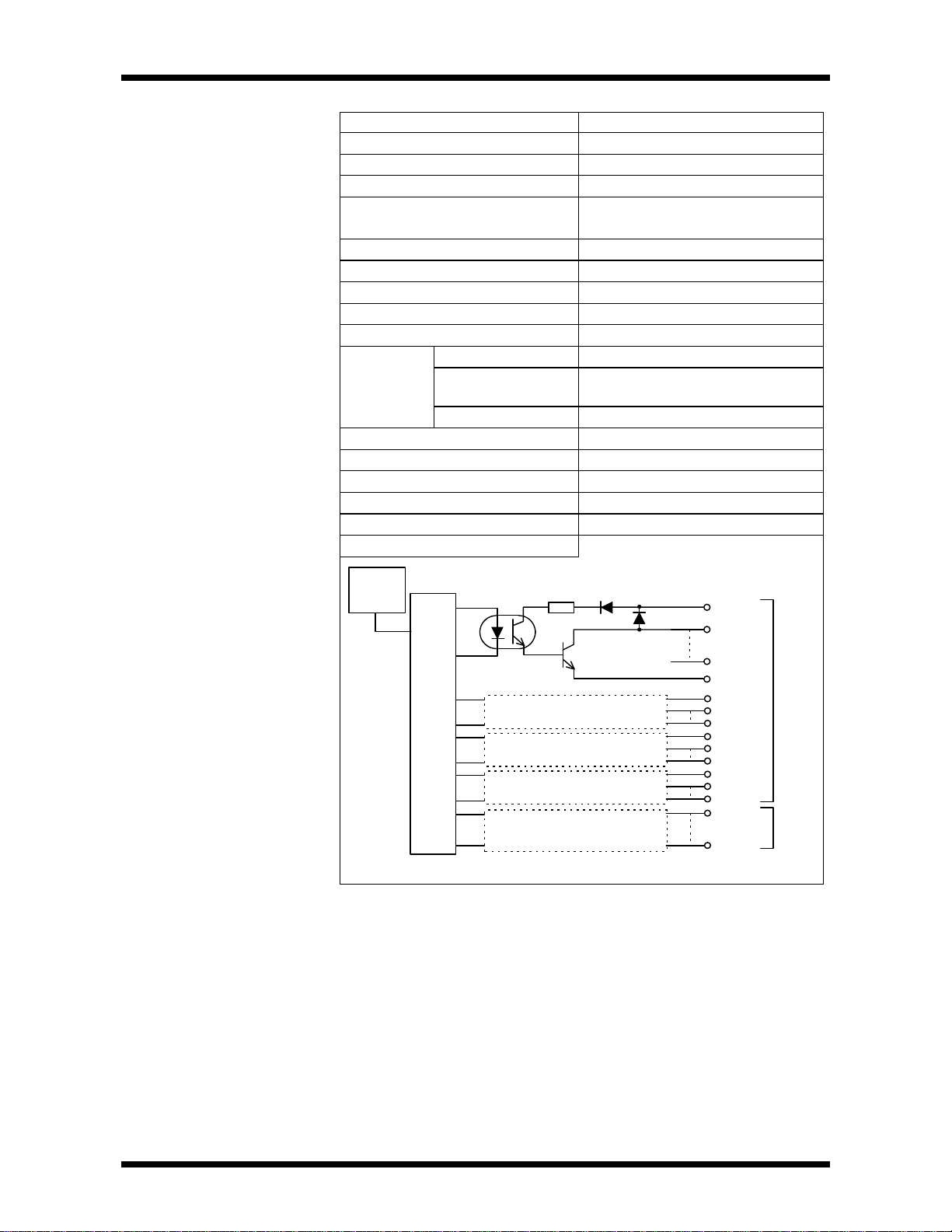
2.Specification
CN2
CN1
LC18LP24L1
HC0
0H
P24H0
HC1
8H
P24H1
HC1
P24L0
64-point Transistor Output
Item DO235
Output type Current sinking
Number of output 64 points
Load Voltage 5-24Vdc +10%/-5%
Output ON Current 0. 1A/point (9.6 - 26.4Vdc)
0.05A/point (4.5 - 9.5Vdc)
Saturation voltage when ON 0.4V or less
Leakage current when OFF 0.1mA or less (24Vdc)
ON delay 1ms or less
OFF delay 1ms or less
External Connections 2 x 40pin connectors
Number of Common 8
Common
Configuration
Number of Output
points per common
8 points
Common Polainty minus
Current Consumption 250mA (5Vdc) or less
Withstand voltage 1500Vac/1 minute
Built-in fuse none
Surge Protection Diode
Weight Approx. 250g
Circuit Configuration
LED
display
Internal Circuit
P24L0
0L
∼
7L
LC0
32 PROSEC T2N
Page 48

2.Specification
0H
FL
P24H1
HC1
P24L1
LC1
FH
0L
A B
B A
L
H
H
L
Terminal Connections
CN1
(B)(A)
20 20
19 19
18 18
EH
17 17
DH
16 16
CH
15 15
BH
14 14
AH
13 13
9H
12 12
8H
HC0
7H
6H
5H
4H
3H
2H
1H
0H
11 11
10 10
9 9
8 8
7 7
6 6
5 5
4 4
3 3
2 2
1 1
P24H0
EL
DL
CL
BL
AL
9L
8L
P24L0
LC0
7L
6L
5L
4L
3L
2L
1L
0L
1L
2L
3L
4L
5L
6L
7L
LC0
P24L0
8L
9L
AL
BL
CL
DL
EL
FL
LC1
P24L1
CN2
(A)(B)
1 1
2 2
3 3
4 4
5 5
6 6
7 7
8 8
9 9
10 10
11 11
12 12
13 13
14 14
15 15
16 16
17 17
18 18
19 19
20 20
1H
2H
3H
4H
5H
6H
7H
HC0
P24H
08H
9H
AH
BH
CH
DH
EH
FH
HC1
P24H
CN2
20
CN1
1
: Load Power Supply
5-24Vdc
1
20
CN1-L=YWn
CN1-H=YWn+1
CN2-L=YWn+2
CN2-H=YWn+3
Connectors on the Module : FCN-365P040/AU (made by Fujitsu)
Cable side connectors : Soldering type (standard attached)
Connector : FCN-361J040-AU (made by Fujitsu)
Connector cover : FCN-360C040-E (made by Fujitsu)
User’s manual 33
Page 49

2.Specification
........
........
Transistor array
LED display
−
16-point Transistor Output
DO233P
0 1 2 3 4 5 6 7
8 9 A B C D E F
0
1
2
3
4
5
6
7
8
9
A
B
C
D
E
F
+
-
12-24Vdc OUT
Item
Load power supply
12-24Vdc+10%/-5%
DO233P
(TDO233P*S)
(Internal current consumption 35mA or less)
1A/point (external power supply 7V or more)
Output ON current
Output ON resistance
1.2A/4 points (4-element transistor array)
1.5Ω or less
Number of output points 16 points (single plus common)
On Delay 1ms or less
OFF Delay 1ms or less
Leak current when Output
0.1mA or less
OFF
Voltage insulation 1500Vac/ 1 minute
Current consumption 60mA (5Vdc) or less
Weight Approx 200g
Circuit Configuration
0
1
2
3
4
Constant voltage circuit
Terminal Connections
8
C
F
Fuse
(5A)
Common
0
1
3
5
7
9
B
D
F
-
2
4
6
8
A
C
E
+
12 - 24Vdc
34 PROSEC T2N
Page 50

2.Specification
LED display
2-element SSR
100-240Vac OUT
. . . . . . . .
12-point Triac Output
AC61
0 1 2 3 4 5 6 7
. . . .
8 9 A B
0
1
2
3
4
5
6
7
8
9
A
B
Item
AC61
(EX10*MAC61)
Load voltage 100-240Vac +10%/-5%(50/60Hz sine wave)
Output ON current 0.5A/point, 0.6A(2-element SSR)
Saturated ON voltage 1.5V or less (0.3A load)
Number of output points 12 points (4 points / common)
ON Delay 1msec or less
OFF Delay 1/2 cycle of load power supply + 1msec or less
Leakage Current When OFF 1.2mA (100Vac) or less, 3mA (240Vac) or less
Withstand voltage 1500Vac / 1 minute
Current consumption 300mA (5Vdc) or less (20mA/point)
Weight Approx. 250g
Circuit Configuration
0
1
2
3
C1
4
Internal Circuit
Terminal Connections
C1
C2
C3
C2
8
Fuse
(2A)
C3
0
1
3
2
C1
4
5
7
9
B
6
C2
8
A
C3
User’s manual 35
Page 51

2.Specification
J1, J2, J3, J4 jumper plugs are AI21
J1IVJ2I
VJ3I
VJ4I
V
4-20mA/1-5V
1N
1P1N1P
1N
1P1N1P
-
12-24Vdc+
4-Channel Analog Input
Input(8-bit)
AI21
RUN
Item
A121
(EX10*MA121)
A131
(EX10*MA131)
Input range 1 - 5V or 4 - 20mA 0 - 10V
Input Impedance
1 - 5V : 500KΩ or more
4 - 20mA : 250
Ω
500KΩ or more
Number of input points 4 points (N side common) 4 points (N side common)
Resolution 1 - 5V : 0 - 250
0 - 10V : 0 - 250
4 - 20mA : 0 - 250
Overall Accuracy
±1% (FS) ±1% (FS)
4 point (N side common) Approx. 1msec Approx. 1msec
Wire breakage detection Only possible for 4-20mA External Power
Yes Yes
Supply failure detection
Withstand voltage 500Vac / 1 minute 500Vac / 1 minute
Current consumption 50mA 5Vdc or less 50mA 5Vdc or less
External power required
12 - 24Vdc±10% - 50mA 12 - 24Vdc±10% - 50mA
Weight Approx. 200g Approx. 200g
Circuit Configuration
CH1
The AI21 type is set to
current input (4-20mA)
at the factory.
For voltage (1-5V) input,
set J1 - J4 to the V side.
CH2
CH3
CH4
Constant voltage circuit
12-24Vdc
(50mA)
Power source display LED
Terminal Connections
CH1
CH2
CH3
CH4
12-24Vdc
(50mA)
A/D Converter
type only.
• I side : for current (4 - 20mA)
• V side : for voltage (1-5V)
Set for current at the factory
P
N
P
N
P
N
P
N
+
-
Isolate external power supply line
(12 - 24Vdc) from other signal
lines.
Use shielded twisted-pair cables
for analog signals, and ground
the shields securely.
Internal Circuit
36 PROSEC T2N
Page 52

2.Specification
XW
O
F
between the input terminals, the data bits do not become 0. (They
4-Channel Analog Input
(8-bit) (Continued)
A/D Conversion
Digital Value
250 (a)
200
150
100
50
0
(a) 4-20mA range : D = 15.625 x A-62.5
(b) 1-5V range : D = 62.5 x A-62.5
(c) 0-10V range : D = 25 x A
Data Format
4 10
F E D C B A 9 8 7 6 5 4 3 2 1 0
B * * * * * * * D D D D D D D D
20(mA)
Analog value
Digital Value
250
200
150
100
50
0
1 5
(b) (c)
10(V)
Analog value
D = Digital Value
A = Analog Value
D : Data bit (8 bits)
0-250 (H00-HFA)
(Over-voltage/over-current input 255 counts)
B : External line abnormal detection bit
0 = Normal
1 =Abnormal
When all data bits are 0
When all data bits are 1
Current input line open
External power is OFF
* : Always 0
4 words occupied
(X4W)
XWn
XWn+1
XWn+2
XWn+3
CH1
CH2
CH3
CH4
NOTE
1. In the voltage input specification, when there is an open-circuit
become indeterminate between 1 and 250).
2. It is recommended that unused channels be shorted between the
input terminals.
User’s manual 37
Page 53

2.Specification
4-20mA/1-5V
NPNPNPN
P
-
24Vdc+
±10V
NPNPNPN
P
-
24Vdc+
JI1IPPP
NNNNPVJI2
JI3
JI4
4-Channel Analog Input
(12-bit)
AI22
RUN
AI32
RUN
Item
AI22
(EX10*MA122)
AI32
(EX10*MA132)
Input Range 1 - 5V or 4 - 20mA -10 - +10V
Input Impedance
1 - 5V : 1MΩ or more
4 - 20mA : 250
Ω
1MΩ or more
Number of Input Points 4 points (N side common) 4 points (N side common)
0.5% : 25ºC
Overall Accuracy
±
1%FS / 0 - 55ºC
±
Resolution 1 - 5V : 0 - 4000
4 - 20mA : 0 - 4000
0.5% : 25ºC
±
1%FS / 0 - 55ºC
±
-10 - +10C :
-2000 - 2000
Conversion Cycle Approx. 9.6msec/4 channels Approx. 9.6mS/4 channels
Wire Breakage Detection Only possible for 4 - 20mA
External Power Supply
Yes Yes
Break Detection
Withstand Voltage 1500Vac / 1 minute 1500Vac / 1 minute
Current consumption 50mA (5Vdc) or less 50mA (5Vdc) or less
External Power Required
24Vdc ±10% - 50mA 24Vdc ±10% - 50mA
Weight Approx. 200g Approx. 200g
Circuit Configuration
CH1
The AI22 type is set to
current input (4-20mA)
at the factory. When using
voltage (1-5V) input,
reset the jumper plugs
CH2
CH3
CH4
24Vdc+
LED
-
DC/DC Converter
Terminal Connections
CH1
CH2
CH3
CH4
A/D
Converter
24Vdc
(50mA)
JI1, JI2, JI3, JI4 (jumper plugs)
are AI22 type only
I side : for current (4 - 20mA)
V side : for voltage (1 - 5V)
Set for current at the factory
P
N
P
N
P
N
P
N
+
-
Isolate external power
supply line (24Vdc)
from other signal lines.
Use shielded twisted-pair
cables for analog signals,
and ground the shields
securely.
38 PROSEC T2N
Page 54

2.Specification
the input terminals.
4-Channel Analog Input
(12-bit) (Continued)
A/D Conversion
4000 (a)
3000
2000
1000
0
4 10
20(mA)
Analog Value
-10 -5 0 1 5
(a) 4-20mA range : D = 250 x A-1000
(b) 1-5V range : D = 1000 x A-1000
(c) ±10V range : D = 200 x A
Data Format (Input occupies 4 words)
• 4-20mA/1-5V
F E D C B A 9 8 7 6 5 4 3 2 1 0
B * * * D D D D D D D D D D D D
D : Data bit (12 bits)
0-4000 (H0000-H0FA0)
B : External line abnormal detection bit
0 = Normal
1 = Abnormal
(Current input line open, or external power OFF)
Digital ValueDigital Value
4000
3000
2000
1000
-1000
-2000
D = Digital value
A = Analog value
(b)
(c)
10(V)
Analog Value
* : Always 0
• ±10V
F E D C B A 9 8 7 6 5 4 3 2 1 0
S S S S S D D D D D D D D D D D
S : Sign bit
0 = Positive
1 = Negative
D : Data bit (11 bits)
- 2000 - 2000 (HF830 - H07D0)
2's complement if negative
NOTE
1. In the voltage input specification, when there is an open-circuit
between the input terminals, the data bits do not become 0.
2. It is recommended that unused channels be shorted between
User’s manual 39
Page 55
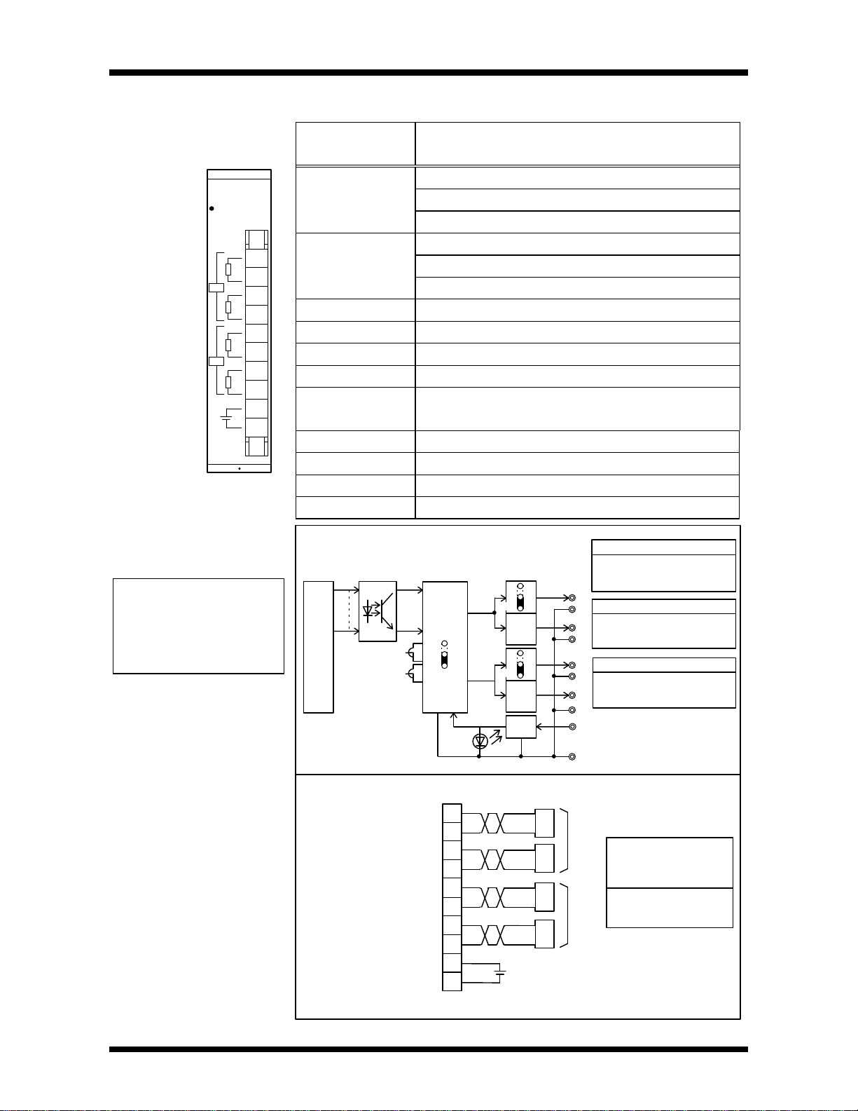
2.Specification
Use shielded twisted-pair
Down side short : 10V
Down side short : 10V
+
CH2
CH1
+V
+I1
+V
+I2
0V
J1
J2
J21
J11
(CH1, CH2 operation)
1V1I2V2
5/10V 20mA
CH
−
24Vdc+
V
1N
1PI1N
1PV1N1P1N
1P
CH
2-Channel Analog Output
(8-bit)
A031
RUN
Item
AO31
(EX10*MA031)
1 - 5V, 4 - 20mA paired output
Output Range 0 - 10V
0 - 5V
5V full-scale terminal : 5KΩ or more
Load Impedance
10V full scale terminal: 10KΩ or more
20mA full-scale terminal : 600Ω or less
Number of Output Points 2 points (each voltage, current pair) (each N side common)
Resolution 0 - 250 (full-scale)
Overall Accuracy
± 1% (FS)
Conversion Cycle Approx. 1msec
External Power Supply
No
Break Failure
Voltage Insulation 1500Vac / 1 minute
Current Consumption 70mA (5Vdc) or less
External Power Supply
24Vdc ± 10%-90mA
Weight Approx. 200g
The A031 type is set to
1-5V, 4-20mA setting
at the factory. Refer to the
circuit configuration for
other settings.
Circuit Configuration
Internal circuit
Terminal Connections
D/A
Converter
Constant-voltage
circuit
Power supply display LED
P
N
P
N
P
N
P
N
+
-
I
24Vdc
(90mA)
J1, J2 switching jumper
J2 short : Reference value 0V (0mA)
J1 short : Reference value 1V (4mA)
1
P
J11 switching jumper
N
Output voltage level for CH1
P
Up side short : 5V
N
2
P
J21 switching jumper
N
Output voltage level for CH2
Up side short : 5V
P
N
24Vdc
-
CH1
Isolate external power
supply line (24Vdc)
from other signal lines.
cables for analog signals.
CH2
40 PROSEC T2N
Page 56

YW
0
F
2-Channel Analog Output
(8-bit) (Continued)
2.Specification
D/A Conversion
Analog Value (mA)
20 (a)
10
Analog Value (V)
10 (c)
5 (b)
4
0
50 100150 200250
(a) 4-20mA range : A = 0.064 x D + 4
(b) 1-5V range : A = 0.016 x D + 1
(c) 0-10V range : A = 0.04 x D
Data Format
F E D C B A 9 8 7 6 5 4 3 2 1 0
* * * * * * * * D D D D D D D D
D : Data bit (8 bits)
0-250 (H00-HFA)
* : No effect (No effect on D/A conversion)
2 words occupied
(Y2W)
YWn
Ywn+1
1
0
50 100150 200250
Digital ValueDigital Value
A = Analog value
D = Digital value
CH1
CH2
NOTE
When executing direct output, two registers (both channels)
should be specified to output.
User’s manual 41
Page 57
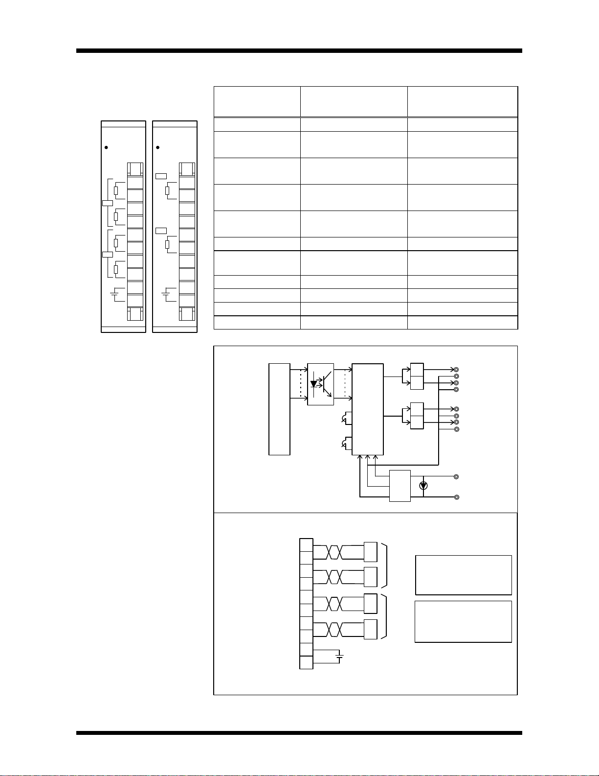
2.Specification
AO22
−
24Vdc+
N
PINPNPN
P
CH
± 10V
AO32
−
24Vdc+
NPN
P
−
+
1V1I2V2
24Vdc
CH1
V1
I
CH2
V
I
CH1
CH2
•••
•••
•
2-Channel Analog Output
RUN
4-20mA/1-5V
(12-bit)
RUN
Item
Output Range 1 - 5V or 4 - 20mA
Load Impedance
1-5V : 5KΩ or more
4-20mA : 600Ω or less
Number of Output Points 2 points (each N side common)
(voltage, current pair)
Resolution 1~5V : 0~4000
4~20mA : 0~4000
Overall Accuracy
± 0.5%FS/25°C
± 1% FS/0~55°C
Conversion Cycle Approx. 1mS Approx. 1mS
External Power Supply
FailureDetection
No No
Withstand voltage 1500Vac/ 1 minute 1500Vac / 1 minute
Current Consumption 170mA (5Vdc) or less 170mA (5Vdc) or less
External Power Required
24Vdc ± 10%-90mA 24Vdc ± 10%-90mA
Weight Approx. 200g Approx. 200g
Circuit Configuration
Internal circuit
AO22
(EX10*MAO22)
D/A
converter
(EX10*MAO32)
10 − + 10V
−
5KΩ or more
2 points (each N side common)
10~ + 10V :−2000~2000
−
± 0.5%FS/25°C
± 1% FS/0~55°C
1
*
2
2
*
AO32
P
N
P
N
P
N
P
N
42 PROSEC T2N
*AO22 only
Terminal Connections
LED
DC / DCconverter
P
N
P
N
P
N
P
N
I
24Vdc
(90mA)
*AO22 only
CH1
*
CH2
*
Isolate external 24Vdc
line from other signal
lines.
Use shielded twistedpair cables for analog
signals.
Page 58

Digital Value
Digital Value
YW
2's complement if negative
YW
2-Channel Analog Output
(12-bit) (Continued)
2.Specification
D/A Conversion
20
10
4
2000 4000
(a) 4-20mA range : A = 0.004 x D + 4
(b) 1-5V range : A = 0.001 x D + 1
(c) ±10V range : A = 0.005 x D
Data Format (Output occupies 2 words)
• 4-20mA / 1-50
(a)
Analog Value (V)Analog Value (mA)
10 (c)
5 (b)
1
-2000 2000 4000
0
-5
-10
A = Analog value
D = Digital value
F E D C B A 9 8 7 6 5 4 3 2 1 0
* * * * D D D D D D D D D D D D
D : Data bit (12 bits)
0-4000 (H0000-H0FA0)
* : No effect (No effect on D/A conversion)
• ± 10V
F E D C B A 9 8 7 6 5 4 3 2 1 0
* * * * S D D D D D D D D D D D
S : Sign bit
0 = Positive
1 = Negative
D : Data bit (11 bits)
- 2000 - 2000 (HF830 - H07D0)
NOTE
When executing direct output, two registers (both channels) should
be specified to output
User’s manual 43
Page 59

2.Specification
PI21
12-24Vdc
EXT
A
EXT
EXTBA12
A5
B12B5M12M5UNV
BUD
UPDW
Input circuit
BIP
Circuit Configuration
Single-Channel Pulse
5/12V PULSE IN
At the factory setting, the
PI21 is set to 12V input,
quadrature and normal
counter operation. See
the Circuit Configuration for
other settings
Input
A
Item
Input Voltage A, B, M
Range EXT 12~24Vdc +10% -15%
BEXT
Minimum ON A, B, M 9V (12V setting), 3.5V (5V setting)
12V ± 10% / -5% (12V setting), 5V +10% / -5% (5V setting)
Voltage EXT 9.6V
Maximum OFF A, B, M 2V (12V setting), 1V (5V setting)
Voltage EXT 3.6V
Input Current
A, B, M 12V-7.5mA (12V setting), 5V-10mA (5V setting)
EXT 24V-10mA, 12V-5mA
Number of Input Points 1 point phase A, B, M and ETX
Pulse Counting Speed
100Kpps (max) (pulse-width 4µ sec or more)
Counter Configuration 24-bit binary
Pulse Input Mode
Quadrature
Up/Down Phase A: count up / phase B: count down
Phase A, B (90 degree phase shift), up/down
Normal Counter clears at simultaneous ON timing of phase M and
EXT input (edge), always executes count apart from this.
Counter Operation
Mode
Hold Executes count only when both phase M and EXT input are ON,
count stops when either is OFF (Count value maintained).
(Counter clear is at the same timing as the Normal Mode).
External (EXT) Input Operation Counter clears at simultaneous ON timing of phase M and
EXT input (edge)
External (EXT) Input Delay ON-OFF, OFF-ON each 5mS or less
Withstand Voltage 1500Vac / 1 minute (but except between each of the A, B, M
phases)
Current Consumption 80mA (5Vdc) or less
Weight Approx. 200g
PI21
(EX10*MP121)
44 PROSEC T2N
Current when ON
+A
-A
+B
-B
+M
-M
_5/_12 Switching Jumper
5 : 5V input
12 : 12V input
sets all 3 A, B, M
points identically.
shows setting on
delivery
Operation
setting
Counter re-set
(edge detection)
BIP/UPDW Switching Jumper
BIP : Quadrature
UPDW : Up/down
BUD/UNV Switching Jumper
BUD : Normal mode
UNV : Hold mode
supply seitched ON)
Counter (0 when power
Page 60

2.Specification
EXT
12-24Vdc
encoder
A
power
Single-Channel Pulse Input
(Continued)
Terminal Connection
Wiring Example
Encoder
12Vdc
(5Vdc)
Pulse
B
M
OV
5/12Vdc
+A
-A
+B
-B
+M
-M
Use shielded
twisted-pair cables
for pulse signals,
and ground the
shields securely.
PI21
+A
-A
+B
-B
+M
-M
EXT
12-24Vdc
Data Format
XWn+1XWn
8F
7
Occupies 2 words
223-----------216215-----------------2
CountCountSAll bits S
For the count values (24 bits), the lower 16 bits are read as XWn + 1, and the
upper 8 bits as the bit 0 to bit 7.
Count = -8388608 to 8388609 (or 0 to 16777215 if upper 8 bits are masked).
NOTE
Bit 8 to bit F of XWn are the same as bit 7 of XWn (sign bit). In
order to match the double-length register configuration of the T2N,
use after exchanging the upper word and the lower word.
(Example : Store count value in the double-length register of
D0101 • D0100)
[XWn MOV D0101]
[XWn+1 MOV D0100]
00 F
0
User’s manual 45
Page 61

2.Specification
(Continued)
Single-Channel Pulse Input
Pulse Input Mode
< Quadrature >
A
B
< Up/down >
A
B
Count Operation Mode
< Normal >
Phase A/B
Up
Down
phase M
EXT
16777215
Count up
Count up Count down
Count down
Count value
0
< Hold >
Phase A/B
Up
Down
phase M
EXT
(Holding)
Count value
0
NOTE
When executing direct input, two registers should be specified to
input.
(Holding)
46 PROSEC T2N
Page 62

.
.
MC11
PC
12
1CNPROGMR
PROGMR
A B
2.Specification
Single-Axis Position
Control
RUN
ZLS
OT
PLS
Item
Number of Control Axes
Control Units
Control Range
Point Data Capacity
Maximum Speed
Operating Speed Selection
Acceleration/deceleration System
Acceleration/deceleration Time
Backlash Compensation
Zero Position Offset Amount
Dwell Time
I/O occupancy points
Parameter Storage
External
Input
Input Voltage
Input Current 10mA (when 24V input)
ON/OFF Voltage
ON/OFF Delay
External
Output
Pulse
Output
Mode Switch Setting
Output Method
ON/OFF Delay
RUN
Output
Output Method
Operation
Internal
Current
Consumption
External
MC11
(EX10*MMC11)
1 axis
Pulse, inch, mm, etc.
± 999,999
64 points
200kpps
Origin return speed, Maximum speed,
Minimum speed
Automatic trapezoidal / triangular system
0 - 26 seconds
0 - 1000 pulses
± 999,999 command units
0 - 99 seconds
X + Y 4 W (64 bits)
EEPROM
12/24Vdc (zero marker: 5/12/24V)
9.6V / 3.2V
5msec (zero marker: 1msec)
CW/CCW error counter clear
PULSE/DIR (pulse/direction), error counter clear
Open collector (5-24V, 50mA)
2µS
Open collector (5-24V, 50mA)
ON during normal operation
200mA
400mA- (when HP connected)-5Vdc
100mA-12 / 24Vdc
Connector Arrangement
HUN output (0V) 1 1 RUN output
CW pulse/pulse output (0V) 2 2 CW pulse/pulse output
CCW pulse/direction output (0V) 3 3 CCW pulse/direction output
Error counter clear output (0V) 4 4 Error counter clear output
Zero marker pulse input (0V) 5 5 Zero marker pulse input (DC5V)
Zero marker pulse input (0V) 6 6 Zero marker pulse input (DC12/24V)
Ongin position input 7 7 Ongin position input(DC12/24V)
HOLD input 8 8 HOLD input (DC12/24V)
Emergency stop input 9 9 Emergency stop input (DC12/24V)
CW side overtravel limit SW input 10 10 CW side overtravel limit SW input (DC12/24V)
CCW side overtravel limit SW input 11 11 CCW side overtravel limit SW input (DC12/24V)
Extemal power supply (0V) 12 12 Extemal power supply (DC12/24V)
A B
NOTE
Connector on the Module:
FCN-365P024-AU (made by Fujitsu)
Cables side connectors
Soldering type (standard attached)
Connector FCN-361J024-AU (made by Fujitsu)
Connector cover FCN-360Co24-E (made by Fujitsu)
User’s manual 47
Page 63

2.Specification
Zero marker pulse input (5Vdc) : B5
Zero marker pulse input (0V) : A5
Normally Open-Contact Use
Zero marker pulse input (12/24Vdc) : B6
Zero marker pulse input (0V) : A6
Normally Closed-Contact Use
A1 : RUN output (0V)
B1 : RUN output
B12 : External power supply (12/24Vdc)
Constant-voltage circuit
A2 :CW pulse / pulse output (0V)
B2 : CW pulse / pulse output
A3 : CCW pulse / direction output (0V)
B3 : CCW pulse / direction output
A12 : External power supply (0V)
A4 : Error counter clear output (0V)
B4 : Error counter clear output
Single-Axis Position Control
(Continued)
Input Circuit
Origin position input (12/24Vdc)
HOLD input (12/24Vdc)
Emergency stop input (12/24Vdc)
CW overtravel limit SW input (12/24Vdc)
CCW overtravel limit SW input (12/24Vdc)
B7
A7
B8
A8
B9
A9
B10
A10
B11
A11
Note : For the Zero marker pulse input use only one of
5Vdc or 12/24Vdc.
Output Circuit
48 PROSEC T2N
Page 64

2.Specification
RXD
DSR
12RXD
TXD3TXD
RXD4DTR
DSR5SGSG6
DSR
DTR75Vdc
8
9
Serial Communication
Interface
Item
Common memory 160 words × 2
Transmission mode Full-duplex
Synchronizing asynchrounus (Start-stop method)
Interface Conforms to RS232C 1CH
Transmission Code ASCII
Frame Format Start bit : 1bit
Data : 7 or 8bits
Parity : even/odd/none
When none parity is selected,the data bit
length must be 8 bits.
Stop bit : 1 or 2bit
When 2 stop bits is selected,the data bit
length must be 7 bits.
Transmission Speed 300,600,1200,2400,4800,9600,19200bps
I/O occupancy points i X+Y 4W
Data exchange system By READ/WRITE instructions of the T2E
LED Display Transmission data
Isolation none(between RS232C Port and internal circuit)
Current Consumption 550mA or less
CF211
(TCF211**S)
Circuit Configuration
T2N
I/O
bus
External Connections
2port
buffer
RAM
CPU
ROM
I/O
I/F
Reset switeh
RS232C
I/F
TXD
DTR
D-SUB 9pin(female)
User’s manual 49
Page 65

2.Specification
50 PROSEC T2N
Page 66

2
•
•
3.1
Input Modules
Application Precautions
3.Application Precautions for I/O Modules
(1) Minimum ON/OFF time of input signal
The conditions for guaranteed reading of the ON/OFF states of the input
signal are:
Input ON time ON delay time + 1 scan time
Input OFF time OFF delay time + 1 scan time
Therefore, be sure to use longer times than these for the ON/OFF times of
the input signal.
(2) There are some contacts for which the reliability of contact cannot be
guaranteed at the specified input current, depending on the contacts. In
such cases, install an external bleeder resistor and pass a dummy current.
Input Module
I I
V
1
I
2
V
R=
I − I
1
Wattage P> X 3
V
R
(3) The following are examples of connection with transistor output equipment
(such as proximity switches).
NPN open collector type (+common)
Input Module
PNP open collector type (-common)
Input Module
(4) When using a switch with an LED, if the LED-lighting current flows even
when the switch is OFF, it sometimes cannot be recognised as OFF. In
this case install bleeder resistor R and decrease the input impedance.
LED
r
Input module
R
User’s manual 51
Page 67

3.Application Precautions for I/O Modules
(5) When applying an AC input signal, if the external cables are long or if the
number of cores of a multi-core cable is large, a current induced from the
charged wires will flow in the open wire, depending on the mutual
capacitance between the cables. Sometimes a voltage may be
generated which reaches the ON level despite the contacts being open.
In this case, the general method is to decrease the input impedance and
lower the input ON level due to the induced current. Install a resistor or a
resistor + capacitor between input and common, or use a multi-core
shielded cable with a small cable capacitance.
Contacts open Current induced from charged wires flow through
cable capacitance
Current induced from charged wires flows through cable capacitance
For the maximum distance of external cable to an AC input module, it is
necessary either to take the above countermeasure within 100m length in
the condition that, out of 20 cores, 19 are charged wires and 1 is an open
wire, or to check whether the input voltage in this condition is less than the
OFF voltage. When handling large numbers of AC input signals,
precautions such as the above are required. Therefore, taking account of
cost of the system as a whole, one method is to study the interface by DC
signals.
(6) When connecting AC output type sensors, sometimes it is not possible to
detect the OFF state due to the leak current when the sensor is OFF.
In this case, counter by installing an external bleeder resistor as shown in
the drawing below.
52 PROSEC T2N
Bleeder resistor
AC output type
sensor
Input
module
Select bleeder resistors using the following points as a guide.
1) When the sensor is OFF, the voltage between the input
terminals must be less than the residual voltage in the OFF state
2) The current when the sensor is ON within the allowable value for
the sensor
3) Determine the wattage of the bleeder resistor by making an
allowance of approximately 3 times the current when the sensor is ON.
Page 68

DC Output Module
Application Precautions
3.Application Precautions for I/O Modules
3.2
(1) The DC output module needs an external power supply to drive
output transistors. For each common, connect the load power to
the approprite terminal.(For details, see 2.3 I/O module
specifications)
If the wrong polarity of the power supply to the terminal is
connected,the module will be damaged. Check the polarity
before connection.
(2) Protection coordination against over-current of DC output module
Type of module Protection
DO31
(16-point
output)
DO32
(32-point
output)
DO235
(64-point
output)
A fuse of 5A per common(16 points) is built in this
DC output module. For an overload and load
short-circuit, the transistor will not be
protected. This fuse,however,protects the DC
output module and the external cable from burn-out.
A fuse of 2A per common(8 points) is built in this
DC output module. For an overload and load
short-circuit, the transistor will not be
protected. This fuse,however,protects the DC
output module and the external cable from burn-out.
The load short-circuit,etc. will cause burn-out of the
module and external cable,because a protection fuse is
not built in this DC output module. Therfore, install an
appropriate fuse on the outside to prevent accidental
burn-out.
(3) A diode as shown in the figure below is built in to protect the
transistor from transient overvoltage.
D
D: Bypasses transient overvoltage to the power supply and suppresses
the voltage between the collector and emitter of the transistor.
User’s manual 53
Page 69

3.Application Precautions for I/O Modules
D
COM
P24
+
-
+
-
OUT
24Vdc
(4) Pay attention to the following cases caused by the diode mentioned in (3).
〈Case1〉
When connecting to the external equipment in which DC power supply
is provided from internal,if the voltage of P1 is higher than one of P2 or
if P2 turns to OFF when P1 is ON, the external equipment may turn to
ON in spite of the output status.
Because a load current flows through D:a diode.
External eguipmentDC Output module
IN
A
P2
COM
A power supply should be basically used for P1 and P2.
In the above case,insert a diode for preventing a back current
in the position A so that a back current is prevented from
flowing into P2.
〈Case2〉
When the power cable connected to the P24 terminal is cut off,
external load may be driven because the load current of OFF output
circuit(OUT0) flows through the diode and the transistor of ON output
circuit(OUT1) as shown below.
DC Output module
OFF
OUT0
Load
L
P1
54 PROSEC T2N
ON
OUT1
P24
COM
Cutting off
Pay attention for preventing a P24 line from cutting off.
Load
L
Page 70

3.Application Precautions for I/O Modules
(5) If a capacitive load is connected, rush current will flow when
output is charged to ON.
At that time, necessary measures must be taken to protect the output
transistor from being destroyed by the rush current.
To limit the rush current there are two effective measures. One is to
connect a resistor to the load in series. The other is to apply dummy current
to the load by conncting a resistor between the output terminals.
(6) If an inductive load is connected, transient overvoltage will occur when the
output is changed to OFF.
This surge voltage will be absorbed into the diode D mentioned
before so that the transistor will be protected. However,if the output cable
is installed closely to other signal lines, the surge voltage may cause other
problem. In this case, install a flywheel diode in parallel with the inductive
load (as near as possible to the load).
Transistor
Output
module
L
A suitable surge absorption element should be selected according to the
application.
•Flywheel diode Peak inverse voltage:
(for voltage clamping) 3 times the power supply
voltage or more
Forward current:
Load current or more
‚Varistor Rated voltage about
(for voltage clamping) twice the maximum(peak)
power supply voltage.
ƒSnubber(CR) R:0.5 - 1Ω per 1V coil
voltage circuit(for high voltage
frequency attenuation) C:0.5 - 1µF per 1A coil
current
(Non-polar capacitor)
User’s manual 55
Page 71

3.Application Precautions for I/O Modules
L
3.3
Triac Output Module
Application Precautions
(1) Over-Current Protection Coordination
One 2A fuse per 4 output points is mounted in the triac output module.
Although, taking account of protecting elements by the fuse blowing even
in load short circuits, when the fuse blows the semiconductors are
subjected to considerable damage. Therefore, take care in handling and
wiring so that short circuits will not occur.
(2) Output Surge Protection
Triac
output
module
A suitable surge absorption element should be selected according to the
application.
1. Varistor (for voltage
clamping)
(peak) voltage
Surge absorption element
Rated voltage about 1.2 times
the maximum power supply
3.4
Relay Output Module
Application Precautions
2. Snubber (CR) circuit
(for high-frequency
attenuation)
(1) It is necessary to supply a +24V power supply to the internal control circuit
of the relay output module. Therefore, connect a 24Vdc + 10% power
supply between the + and - terminals.
(2) No overload protection fuse is built into the relay output module.
Therefore, always install a fuse suited to the current capacity.
12-point relay output module
Fuse
(3) Output Surge Protection
The installation of a surge absorption element for the induced load, as
described in the paragraphs on the transistor output module and the triac
output module, is recommended.
R : 0.5-1Ω per 1V coil voltage
C : 0.5-1µF per 1A coil
current
(Non-polar capacitor)
NOTE
Please note that, if it is
not protected with a
fuse, the module
pattern will burn out
when there is a load
short-circuit.
56 PROSEC T2N
Page 72

(1)
(2)
(3)
Analog
Analog
Analog
3.5
Analog Input Module
Application
Precautions
3.Application Precautions for I/O Modules
(1) Use a shielded twisted-pair cable for the analog input signal line, and wire
over the minimum distance. Carry out the grounding of the cable shield on
the analog input side(the T2N side).(1) in the dwawing below is the basic.
Sometimes, operation is more stable if the wiring is as in (2)or(3).
input
module
input
module
input
module
(2) Sometimes the conversion values are unstable,depending on the voltage
state of the external 24Vdc power supply.
If the conversion result is not stable, make the external power supply for
analog use a dedicated power supply.
Use of the 24Vdc external supply power source of the T2N power supply
module is recommended.
(3) All intrinsically shielded cables are fitted with ferrite choke adjacent to
analog inputs/outputs, and must have ground connections to grounded
metalwork within 5cm for applying to the EMC Directive.
User’s manual 57
Page 73

3.Application Precautions for I/O Modules
Analog
Analog
Analog
3.6 Analog Output Module Application Precaution
(1) Use a shielded twisted-pair cable for the analog output signal line, and wire
over the minimum distance. Carry out the grounding of the cable shield
on the load side. (1) in the drawing below is the basic.
Sometimes, operation is more stable if the wiring is as in (2) or (3).
output
module
output
module
output
module
(2) Sometimes the conversion values are unstable, depending on the voltage
state of the external 24Vdc power supply.
If the conversion result is not stable, make the external power supply for
analog use a dedicated power supply.
Use of the 24Vdc external supply power source of the T2N power supply
module is recommended.
(3) All intrinsically shielded cables are occasionally fitted with ferrite choke
adjacent to analog inputs/outputs, must have ground connections to
grounded metalwork within 5cm for applying to the EMC directive.
58 PROSEC T2N
Page 74

4.1
Operating Enviroment
4.Installation and Wiring
When installing the T2N,avoid the following locations.
(1) Where the ambient temperature exceeds the 0-55°C range.
(2) Where the relative humidity exceeds the 20-90% range.
(3) Where there is condensation due to sharp temperature variations.
(4) Locations subject to vibration in excess of the permissible value.
(5) Locations subject to shock in excess of the permissible value.
(6) Where there are corrosive gases or flammable gases.
(7) Where there is dust,salinity or iron particles.
(8) Locations exposed to direct sunlight.
When installing the panel which houses the T2N, take note of following items.
(1) Install as far away as possible from high-voltage panels and power
panels.(200mm or more)
(2) When there are high-frequency machines or equipment,securely ground
the housing panel.
(3) When using the same channel base as other panels,ensure there are no
leakage current from the other panels and equipment.
User’s manual 59
Page 75

4.Installation and Wiring
4.2
Installing the Rack
Power line Installation dimensions
200mm
or more
Basic unit
70mm
or more
Expansion unit
248(BU266)
314(BU266)
380(BU228N)
Installation Precautions
(1) Since the T2N is not of dust-proof construction, install it in a dust-proof
control panel.
(2) Avoid installing the units directly above equipment which generates large
amounts of heat (such as heaters, transformers and large capacity
resistors).
(3) Taking account of safety in maintenance and operation, either isolate at
least 200mm from high-voltage equipment and power equipment, or
separate by shielding, such as steel plate.
(4) Separate at least 200mm from high-voltage lines and high power lines.
(5) For ventilation, leave an air space of at least 70mm around the units.
(6) In paticular, in the vicinity of high-voltage and power equipment, it is
necessary to give consideration to grounding.(See 4.5 Grounding)
(7) In the units, the power supply modules are always positioned on the left-
hand side. Install them vertically on the mounting frame.
Do not install them in the direction except it.
(8) Mount the units securely, using the rack mounting screws of M4 size.
(Screws torque : approx.1.47N ⋅ m=15kgf ⋅ cm)
60 PROSEC T2N
Page 76

(optional)
4.3
Mounting the Modules
4.Installation and Wiring
Always mount the power supply module in the left end slot of the rack.
Also, mount the CPU module in the slot next to the power supply module of
the basic unit.
Execute the following procedure for module installation.
(1) Taking care that they are securely
inserted in the slots of the base unit,
install modules in sequence starting
with the power source module at the
left end.
(2) Push securely until the front panel of
the module clicks into the base unit.
NOTE
1.For safety, always turn power OFF before installing and removing
modules or installing and removing terminal blocks.
2.After installing the modules, secure the unit so that it can be
mounted vertically, including when in transport.
4.4 Connecting the Expansion Unit
Expansion
cable
Up to three expansion units (8-slot or 6-slot) can be connected in the T2N.
For the expansion units, use BU268 (8-slot) or BU266 (6-slot).
Expansion connectors
Basic unit
Expansion unit
FG terminals (Single-point grounding)
(For details, see 4.5 Grounding)
CPU module
Power supply modules
70mm or
more(for
ventilation)
NOTE
2 expansion connectors are fitted on the 5-slot I/O type (BU266) and the
7-slot I/O type (BU268) racks. The right-hand connector is for input from
the previous unit, the left-hand is for output to the next unit.
User’s manual 61
Page 77

4.Installation and Wiring
4.5
Grounding
Grounding Point
It is advisable, for the grounding of electronic devices to carry out dedicated
grounding which is isolated from that of power systems, and to carry out
single-point grounding between 2 or more electronic devices. In the T2N,
noise-proofing is designed which takes the actual application into account, and
it has a satisfactory noise-immunity without carrying out grounding of the device
itself. However, as a precaution, correct grounding is recommended from the
viewpoint of reliability.
Carrying out grounding, check against the following criteria.
NOTE
1. Separate the expansion cables as far as possible from other cables. In
particular, isolate them at least 200mm from power lines.
2. 4 types of expansion cables are available - 0.3m, 0.5m, 0.7m and 1.5m.
Select according to the positions of the units.
(1) The electronic equipment case must not become a path for a ground
current. (High-frequency currents are particularly harmful)
(2) Equalise the ground potentials when 2 or more units of electronic
equipment are to be connected. (Single-point grounding is best)
(3) Do not connect to power system earths. (High-frequency isolation is
necessary)
(4) Do not connect to unstable earths. (parts with unstable impedance such
as painted screws, and parts subject to vibration)
62 PROSEC T2N
Page 78

4.6
Grounding Methods
4.Installation and Wiring
(1) Installation of a Conductive Panel.
When the mounting frame itself has good conductivity, and is not in
common use with the earths of other power systems, proceed as below.
Power supply module
FG connection (when not on the same panel)
Dedicated ground
NOTE
Conductive panel
(mounting frame)
Screws in 4 locations
(unpainted)
When not on the
same frame as
the basic unit,
insulate the
installed portion
and connect
between FG
terminals, via the
shortest distance
When the mounting frame does not possess good conductivity, or when
the frameground is a power system earth or is an unstable ground, use
the insulated installation shown in (2).
User’s manual 63
Page 79

4.Installation and Wiring
(2) Isolated Installation
When the mounting frame has an unstable earth potential, or when it is not
conductive, securely mount the unit with isolation, as shown below.
Power supply modules
Basic unit
Isolate from the
mounting surface
Expansion unit
FG wiring (2mm2) shortest wiring
Dedicated single-point ground
(3) When there is no grounding point
When suitable grounding is not available (no dedicated grounding point),
mount by the method of (2) Isolated Installation.
There is no problem with operation if there is mutual connection between
the FG terminals of the T2N itself. However, for safety, carry out singlepoint grounding via an impedance* close to the frame.
* ;
When a resistor : Ground the frame via 1W-1Ω approx.
When an inductance : Ground to the frame via 2A-100µH approx.
64 PROSEC T2N
Page 80

RUN
RUN
power supply
Use crimp-style terminals with sheaths as far as possible for wiring to the
power supply module. When it is not possible to use crimp-style terminals
with sheaths, cover with insulating tape so that the conductive parts are not
exposed.
4.7
the Power Supply
Wiring
4.Installation and Wiring
Wire the external power supply to the T2N power supply module in the following
manner.
When using expansion units, arrange for power to be supplied simultaneouly to
the basic unit and the expansion units (or to the expansion units before the
basic unit).
contact
output
Input
power supply
24Vdc
PS31 (24Vdc input)
NC
+
-
NC
FG
FG
contact
output
Input
power supply
PS261 (100 - 240Vac input)
NC
NC
LG
FG
24Vdc output *3
(Total power of the
internal 5V and 24V
output must be
within 15W.
Do not connect it to
other power supply
systems.)
Line filters ground *1 (Connected to the supply
line via capacitors)
*1 : Line Filter Ground(LG)
5000PF or less
Input
5000PF or less
LG
*2 : Frame Gounds(FG)
See 4.5 Grounding for details.
*3 : 24Vdc output
The 24Vdc power cables must be suppressed with ferrite cores, immediately
adjacent to the power supply module(s).
NOTE
Frame ground *2 (Connected to the unit
case)
Normally, the LG and FG terminals are
shorted.
However, depending on grounding
environment (such as when there is a
problem with leakage current or when the
power supply ground is separate), open the
LG terminal or provide a dedicated ground.
User’s manual 65
Page 81

4.Installation and Wiring
4.8
I/O Wiring
Pay attention to the following points when mounting and wiring the I/O modules.
C
P
U
Basic unit
Low-power
systemI/O
Expansion unit
High-power
systemI/O
70mm or more
Low-power
power supply power supply
Low-power
signal duct
Low-Power System I/O
DC input module
Analog input module
Analog output module
Pulse input module
Positioning module
Serial Interface
Transmission module
systemI/O
High-power
systemI/O
200mm or more
High-power
signal duct
High-Power System I/O
AC input module
DC output module
AC output module
Relay output module
Power line
66 PROSEC T2N
Page 82

4.Installation and Wiring
(1) For the positioning of the I/O modules, arrange the low-power system I/O
to the left and high-power system I/O to the right, and keep the wiring
separate.
(2) The gap between units should be at least 70mm for maintenance and
ventilation.
(3) Separate by at least 200mm from power lines and power equipment, or
shield with a steel plate (the steel plate must be grounded).
(4) For the sizes of input/output wiring, see the Table below.
Numbers of Points in Modules Wire Sizes to Use
16-point module 0.5 ∼ 1.25mm
32/64-point module 0.1 ∼ 0.3mm
However, for common lines, use a thicker size which takes account of
the current capacity. Also, for cables outside the panel, the use of cable of
at least 1.25mm2 is recommended to keep the impedance low.
(5) The terminal screws are M3.5. For suitable crimp-style terminals,
use terminals with width 7mm or less for M3.5 screws.
2
2
(6) Both inside and outside the panel, always avoid wiring input/output signal
lines in bundles with, in proximity, or in parallel with high-voltage lines and
power lines. When separation is difficult, use multi-core shielded cable
depending on the type of input/output signals, and make a single-point
ground for the shield at the service entrance in the panel (in the cases of
AC I/O,DC I/O and relay output modules).
(7) Pay attention to 3.Application Precautions for I/O Modules.
CAUTION
!
1.Turn off power before wiring to minimize the risk of electrical shock.
2.Use crimp-style terminals with sheaths as far as possible for wiring to the
power supply module. When it is not possible to use crimp-style terminals
with sheaths, cover with insulating tape so that the conductive parts are
not exposed.
3.Operation without grounding may cause electrical shock or malfunction.
Connect the ground terminal on the T2N to the system ground.
4.Apply power of the specified rating.
Applying excess power voltage to the T2N can cause explosion or fire.
User’s manual 67
Page 83

4.Installation and Wiring
4.9
Power up/down
Sequence
Turn on power or turn off power of the T2N according to the following sequence
so that the T2N is used safely and securely.
(Power up sequence)
(1) Turn on the T2N’s power
(1) Turn on power of the T2N at first. When using expansion units, arrange for
power to be supplied simultaneously to the basic unit and the expansion
units.
Use the same power lines for them.
If it is difficult, turn on power of the expansion units before turing on that of
the basic unit.
(2) Turn on power for I/O modules and loads simultaneously.
Use the same power lines for them.
If it is difficult, turn on the external power for I/O modules before turing on the
power for the loads.
(Power down sequence)
(1) Turn off the external power for I/O modules
and loads.
(1) Turn off the external power for I/O modules and loads simultaneously.
Or turn off power for loads and turn off power for I/O modules in turn.
(2) Turn on the power for I/O modules and
loads
(2) Turn off power to
the T2N.
(2) Turn off power of the T2N.
When using expansion units, turn off power of the basic unit and the expansion
units simulataneously.
Or turn off power of the expansion units after turning off power of the basic unit.
!
CAUTION
1. Configure the external circuit so that the external power required for output
modules and power to the loads are switched off simultaneously.
Also, turn off to the loads before turning off power to the T2N.
68 PROSEC T2N
Page 84

4.10
Safty circuit
4.Installation and Wiring
Configure emergency stop and safty interlocking circuits out of the T2N against
faulty of the T2N or breaking wires.
• Emergency stop circuit
‚ Safty interlocking circuit (forward and reverse etc.)
(Example)
transformer
T2N
emergency
starter
stop
MC
interlocking
(forward and reverse etc.)
Xm
MC2
MC1
MCS
Ym
Ym is ON during RUN
Wating for power up of the
DC power supply
DC power
supply
(+)
R2
R1
MC MC
MC1
MC2
(-)
Relay
Xm is turned to ON aftor
the DC power supply is
set up.
Rl is ON during RUN
The power for loads is
OFF when emergency
stop is active.
S004F
Xm
0.5s TON Tm
Tm
R1
MC
R2
output module
output module
Input module
Ym
User’s manual 69
Page 85

5.Maintenance and Checks
5.1
5.1
Daily Checks
Daily Checks
Recommended daily checks for optimum system performance
Check the LEDs on
the front of the power
supply modules and
CPU module
Check the LED
displays of the input
modules
(Digital input)
Check the LED
displays of the output
modules
(Digital output)
Check the switch
position on the CPU
module
Item Content of Check Countermeasure
when Abnormal
POWER(Red)
:Lit when 5V power
supply normal
RUN(Green)
:Lit when operating
normally
FLT(Red)
:Out when CPU and
I/O normal
BAT(Green)
:Lit when battery
voltage normal
The corresponding LED
should be lit when an
external input signal is
ON.
When the output is ON,
the corresponding LED
should be lit and the
corresponding external
load should operate.
Operation is executed
when the operation mode
switch(HALT/RUN) is to
Run.
When the state of an
LED is not normal, follow
the procedure
in 6.Trouble-shooting.
•Check whether the
input voltage is within
the specified value.
•Check whether there is
any slack in the input
terminal block.
•Check whether the
module is securely
mounted.
•Check whether the
external load voltage is
within the specified
value
•Check the built-in fuse.
•Check whether there is
any slack in the output
terminal block.
•Check whether the
module is securely
mounted.
Put the switch to
the specified position.
70 PROSEC T2N
See Ethernet/TOSLINE-S20LP of the T2N user’s manual regarding status
display LEDs for built-in networking.
Page 86

5.Maintenance and Checks
NOTE
When a serious error (such as system RAM abnormal) is detected
after power is switched ON, the FAULT LED on the CPU will blink.
In this condition, communication with programmer cannnot be
executed. When this condition does not change even if the power is
switched ON again, exchange CPU modules.
User’s manual 71
Page 87

5.Maintenance and Checks
5.2
Periodic Checks
Check the following items periodically (about once every 6 months).Check also
when the operating conditions/enviroment change.
Power Supply
Mounting
Condition
Programmer
I/O Modules
Environment Check that temperature,
Program Check that the contents of the
Battery
Item Check Criteria
Power supply voltage (measure
at the module’s power supply
terminals.)
Is there any slack in the power
supply terminal block screws ?
Is there any damage to
the wires and cables ?
Is the basic unit firmly secured ? Must not be any slack or
Are the expansion units firmly
secured ?
Is each module firmly installed ? Must not be any slack or
Is there any slack in the
expansion cable connctors or
any damage to the cables ?
Is there any problem with the
programmer functions ?
Is there any slack in the
connectors or damage to
the cable.
Measure the voltage at each I/O
terminal block.
Check the input state display
LEDs.
Check the output state display
LEDs.
Are the I/O terminal blocks
firmly secured ?
Is there any slack in the terminal
screws, or is there any risk of
adjacent terminals touching
each other ?
Is there any damage to
the wires and cables ?
humidity, vibration,dust,etc are
within the specified values.
basic program and the master
program (kept on a floppy disk
or the like) agree.
Does the battery require
changing ? (The battery
installation date is recorded on
the optional card cover).
Are the battery connctors firmly
connected ?
85 ∼ 264Vac
20.4 ∼ 28.8Vdc
Must not be loose.
Must not be damaged.
play.
Must not be any slack or
play.
play.
Must not be any slack or
damage.
Execute simple
operations.
Must not be any slack or
damage.
Must be within
the specified values.
Must light when normal.
Must light when normal.
Must not be any slack or
play.
There must not be any
slack or risk of mutual
contact.
Must not be any damage.
Must be within the
general specifications.
Contents must agree
when carrying out
a comparative check
A change is
recommended if 2 years
have elapsed.
Must not be any slack.
72 PROSEC T2N
Page 88

5.Maintenance and Checks
CAUTION
!
1. Turn off power before checking voltage on terminals. Failure to do so can
cause electrical shock.
2.Do not modify the T2N in hardware nor software. This can cause fire,
electrical shock or injury.
5.3
Spare Parts to Keep in
Stock
The following items are recommended minimum spares. These will allow
operation to be resumed immediately in the event of any failure.
Part Quantity Remarks
I/O modules One of each
type used
Fuses Number to be
used
Batteries 1 For emergency use.
CPU modules included
with optional cards
Power supply
modules
Programmer 1set Useful for detecting the cause of a
Master programs As required Keep on FD or the like.
1
1
For the relay contact output,
the contact life must be taken into
account. See Section 2.3.
See Section 5.5.
See Section 5.4.
Keep a minimum of 1 each to
reduce down-time to the minimum.
failure.
CAUTION
!
Do not touch activated terminals of I/O modules and units. Keep the terminal
covers closed during power ON.
This can cause electrical shock or injury.
NOTE
Store batteries in a cool (25°C or less) place as self-descharge is
greater at high temperatures.
User’s manual 73
Page 89

5.Maintenance and Checks
5.4
Battery Replacement
Normally the program and 2kwords data register are kept in the built-in
EEPROM of the T2N. On the other hand, other retentive registers’ value and
real time clock’s value can be kept in the RAM with a battery.
A lithium battery is used, which has little self-discharge and can be used over a
wide temperature range. Therefore, during its period of use, and in paticular
when the non-conducting time is long, it can be used with assurance.
The date of istallation of the battery is recorded on the CPU side panel.
Under normal use, it is recommended that the battery should be replaced every
2 years. Check the date of installation and replace using the following
procedure.
There is an LED(BAT) which indicates normal battery voltage on the front of the
CPU module. This is lit when normal. When this LED flashes or is out,
the battery comes into life. Therefore replace the battery within 14days. (It is
recommended that the power supply should not be switched OFF until actual
replacement, in order to protect the program.)
• Remove the CPU module from the basic unit
after turning power OFF.
ƒ Remove the CPU side panel.
‚ Loosen the screws of the side panel which
mounts a battery with CPU module.
74 PROSEC T2N
Page 90

5.Maintenance and Checks
„ Pull off a connector of the battery. … Inserting a finger into the hole under battery
holder, take off a battery like pushing out.
† Insert a new battery into the holder, supporting
it from the hole by a finger.
ˆ Corresponding the side panel’s holes for
screws with position of metal plates, connect
CPU module and side panel.
‡ Connect the new battery’s connector.
‰ By screwing, connect both CPU module and
side panel.
• Disposal of the battery
Dispose of the battery in the same way as general-purpose dry batteries.
There is a risk of explosion if dismantled or burnt.
If the + and - of a lithium battery are allowed to short, this may lead to igniting
and fumes.
Don not cut the lead wires and do not dismantle the connectors.
User’s manual 75
Page 91

5.Maintenance and Checks
NOTE
1.The battery should be replaced with power OFF. The time with battery
2.When connector of the battery is disconnected, an LED (BAT) is out.
3. When handling the battery, take care of the following points.
4. Do not use a battery which has been stocked more than 3 years since
5.The battery is a dedicated product with lead wires and connectors
removed should be within 5 minutes. If the battery is kept removed for
a long time, the contents of the RAM memory will be erased, so
please take care.
Any error message about the battery can’t be registered in the Event
History Table in this case.
* The voltage is not compatible with manganese dry batteries and
alkali batteries. Do not use these as substitutes.
* Never let the + and - of the battery be shorted.
* Never dismantle batteries, overheat them or put them into a fire.
* Never try to charge a battery. This is not possible.
manufactured date.
attached. Order it from Toshiba.(Product Code:EX25SER6)
5.5
Fuse Replacement
The following fuses are used in the T2N modules.
These fuses are recommended minimum spares and will allow operation to be
resumed immediately in the event of any failure.
Module Fuse Rating Model Quantity
PS31 Glass tube 125V-2A(normal fusion) EX10*SFB20 1Power
Supply
Output
PS261 Glass tube 250V-3A(normal fusion) TFU923*AS 1
DO31 Glass tube 250V-5A(quick fusion) EX10*SFA50 1
DO32 Glass tube 250V-2A(quick fusion) EX10*SFA20 4
AC61 Glass tube 250V-2A(normal fusion) EX10*SFC20 3
76 PROSEC T2N
Page 92

6.1
Troubleshooting
Procedure
6.Troubleshooting
When a problem occurs in the system, having first thoroughly understood the
content of the problem, it is important to determine whether the cause lies on
the mechanical side or on the control system (PLC) side.
Also, the cause of one problem frequently gives rise to secondary problems.
Therefore it is important clearly to determine the cause of the problem by
considering the system as a whole.
When the problem is considered to be in the T2N itself or in the input/ output of
the T2E, first check the following items.
Is the power supply
module “POWER” LED
lit?
Lit
Is the CPU module
“
RUN”LED
Does the problem appear
to be in operation of user
program?
Does the problem appear
to be in the input module?
Does the problem appear
to be in the output
module?
lit?
Lit
NO
NO
OUT
OUT
YES
YES
YES
When the “POWER” LED is out,
refer to 6.2 “Power Supply Check”
When the “RUN” LED is out,
refer to 6.3 “CPU Check”
When the problem appears
to be in the operation of user
program, refer to 6.4 “Program
Check”.
When the problem appears
to be in the input module,
refer to 6.5 “Input Check”
When the problem appears
to be in the output module,
refer to 6.6 “Output Check”
When the problem is temporary, and when the problem occurs with the
synchronisation of system/mechanical operations, the influence of the external
environment (such as noise and power fluctuations) may be considered to be
the cause. Since the items to check in this case are collated in paragraph 6.7,
carry out a check referring to that paragraph.
NOTE
When the cause cannot be determined by the above checks, consult
Toshiba.
User’s manual 77
Page 93

6.Troubleshooting
Power Supply Check
6.2
The following is a flow-chart of checks for use when the POWER LED does not
light even when the power to the T2N is switched ON, or when a power supply
failure occurs after some specified time.
Is the supplied power
voltage within the specified
values?
Within the
allowable values.
Has the power
supply fuse blown?
Not blown
Will the POWER LED light
when all the modules and
the expansion cables other
than the power supply
module are removed?
Lit
Re-check whether the
internal 5V and external
24V current consumption is
within the allowable values.
Within the
allowable values.
Outside the
specified values
Blown
Out The problem lies in the
Outside the
allowed range.
85~264Vac,
20.4~28.8Vdc,
Note: After eliminating
the cause of the
blown fuse, replace it.
See the following
NOTE.
power supply module or
the rack.
Make to total current
consumption of the
CPU and I/O come
within the allowable range.
Mount the modules one
by one, and determine
the state where the
POWER LED goes out.
NOTE
1.When carrying out the above checks, always check each step after
switching the power supply OFF again.
2.When a fuse has blown, always determine the cause of the blown fuse
and eliminate it. If the fuse is replaced and the power supply is switched
ON again without eliminating the cause, there is a risk of progressive
damage to the module.
When the cause of the blown fuse cannot be determined, consult
Toshiba without replacing the fuse.
The module mounted
immediately before the
light goes out is defective.
78 PROSEC T2N
Page 94

6.3
CPU Check
6.Troubleshooting
When the “POWER” LED of the power supply module is lit, but the “RUN” LED
of the CPU module is out, check the following items.
Is the FLT LED blinking?
Out or lit.
Is the FLT LED lit?
Out
Is the CPU module
operation mode switch to
RUN?
YES
Is the RUN/Stand-By
switch set to OFF
(RUN)?
OFF
(RUN)
Is the RUN LED
blinking?
Blinking
Lit
NO
NO
Blinking
When it blinks even if power supply
CPU module is
is on,
Replace the CPU.
An error has occurred.
Check the content of the Event
History.
Shift to RUN.
It starts up in the HALT mode
despite the setting of the operation
mode switch.
Therefore, either shift the operation
mode switch→HALT→RUN or start
RUN from the programmer.
It is in the HOLD mode.
Release HOLD using the
programmer.
defective.
6.4
Program Check
When the control operation does not operate properly although the program is
executed, check the following items.
(1) Is there an output to the same coil or register at 2 or more places in 1 scan,
or, is there an overlap of the device for coil instruction and function block
instruction?
(2) Is there an attempt to input a signal which changes faster than the scanning
cycle?
(3) Is the same timer register or counter register being used for multiple timer
instructions or counter instructions?
(4) When interrupt is in use, is a device or register operating during the interrupt
program which affects the operation of the main program?
(5) Is any EEPROM error occured?(S0039, S0051 is 1.)
In this case, carry out EEPROM write command by the programmer.
User’s manual 79
Page 95

6.Troubleshooting
Input Check
6.5
When unable to read the input signal correctly although the program is being
executed, check the following items.
Does the LED on the input
module go ON/OFF when
external equipment is
switched ON/OFF?
YES
Does the actual I/O module
mounting state agree with
the input/output allocation
information monitored by
the programmer?
NO
Try executing Automatic
I/O allocation.
NO
Was the allocation normal?
NO
Is the problem only the
allocation of a certain input
module?
NO
NO
YES
YES
YES
When there is a problem with the
state of the LED, check the input
voltage when ON/OFF and check
the terminal block for slack.
When it agrees, it is functionally
normal. Error input due to noise is
suspected.
Normal
Check the installation of input
modules. A problem with input
module can also be suspected.
Is there an allocation
problem with all
the expansion units?
NO
Is there an allocation
problem with all the I/O on
the basic unit?
the
I/O on
YES
YES
Check the connections of the
expansion cables and unit number
settings. A problem with the
expansion cables or the expansion
units can be suspected.
The problem lies in the CPU module
or the rack.
80 PROSEC T2N
Page 96

6.6
Output Check
6.Troubleshooting
When there is a problem with the actual operation of output equipment although
correctly outputting to registers and devices on the program, carry out the
following in preparation for checks.
(1) Save the program. (In a floppy disk, EEPROM, etc)
(2) Clear the CPU memory.
(3) Put the ROM/RAM shift switch to RAM (ON).
After making the above preparations, carry out checks in the following
sequence.
Apply power and operate
automatic I/O allocation.
Does the I/O allocation
information agree with the
module mounting state?
YES
Write the END command
only and turn to RUN.
Does the output module
LED go ON/OFF when the
output from the data
setting of the programmer
is ON/OFF?
YES
Is the external power
supply voltage of the
output module normal?
Normal
Has a fuse
(When there is no fuse,
proceed as if fuse not
blown)
Fuse not
blown.
blown
?
NO
NO
Abnormal
A fuse
has blown
A problem with the unit, CPU, I/O
module expansion cables can be
suspected. (See the paragraph on
input checks)
The problem lies in the output
module.
Replace the module.
Adjust the external power supply
voltage to the
of the respective output modules.
Note: After eliminating the cause
of the blown fuse, replace the
fuse.
The problem lies in the output
element.
Replace the module.
specified voltages
NOTE
When a fuse blows, always investigate and eliminate the cause. If the fuse
is replaced without eliminating the cause and the power supply is switched
ON again, there is a risk of progressive damage to the module. When the
cause of the blown fuse cannot be determined, consult Toshiba without
replacing the fuse.
User’s manual 81
Page 97

6.Troubleshooting
Problems
Faults Due to External
6.7
When a problem with the T2N system occurs as one of the following
phenomena, external factors should be suspected.
(1) When the problem occurs in synchronisation with the operation of
input/output equipment
In this case, there is a possibility that the cause is noise generated when
the output equipment switches ON/OFF. Apply the noise countermeasures described in Section 3 Application Precautions for I/O Modules.
(2) When the problem occurs in synchronisation with the operation of peripheral
power equipment and high-frequency equipment
In this case, the effect of noise induced in the input/output signal lines may
be suspected. Also, depending on the power supply system and the
grounding system, the cause may sometimes be surges or voltage
fluctuations in the power supply and fluctuations in the ground potential.
Check with the Notes described in Section 4 Installation and Wiring.
Depending on the case, one method is to try the effect of disconnecting the
ground.
(3) When the problem occurs in synchronisation with the operation of
machinery, the effect of vibration may be considered. Check the state of
installation of units/modules and, at the same time, study vibration
countermeasures, such as the use of vibration-proofing rubber.
(4) When similar problems re-occur even after replacing faulty modules,
thoroughly check that there is no risk of entry of metal particles or drops of
water.
Apart from the above causes, if, for instance, the ambient temperature exceeds
the specified range, stable operation of the system cannot be guaranteed. Take
thorough precautions over the environmental conditions.
82 PROSEC T2N
Page 98

6.8
List of Items for Self-
Diagnostic Check
6.Troubleshooting
When the T2N CPU has detected a problem through self-diagnosis, it registers in
the Event History Table one of the error messages (and associated information)
shown in the Table on the following pages. When the details of the problem are
such that it is not possible to continue operation, the CPU switches all the outputs to
OFF, and stops the operation. (Error Down)
The latest 30 error messages and the times of their occurrence are stored in the
Event History Table, and these can be displayed on the programmer. The times
when any error were occured, can be recorded while the RAM and calendar are
maintained by a capacitor and battery in the T2N. (Power supply ON/OFF can
also be registered)
When the T2N system has been stopped by Error Down, first connect the
programmer and make it display the Event History Table, then check the details
of the error.
The following is the procedure for making the programmer display the Event
History.
(1) Connect the T2N CPU module and the programmer (T-PDS) by a dedicated
cable.
(2) Switch ON the power supply of the programmer (T-PDS). (The power supply
of the T2N system should also be ON)
(3) Start up T-PDS by keying-in TPDS [Enter] from the programmer (T-PDS).
(4) If some key (any key) is pressed, the T-PDS initial menu screen will be
displayed. At this time, “Receive Time Out” should not be displayed.
(5) In this state, if S and E are keyed-in, the Event History will be displayed.
(Example of Event History display screen)
*)The Event History can be registered even if initial set of the calendar is not
executed. In this case, the Date and Time displays will be shown as
“??-??-?? ??:??:??”.
User’s manual 83
Page 99

6.Troubleshooting
When “Receive Time Out” is displayed in Step (4) above, communication
between the programmer and the T2N system has not been established. When
the FLT LED on the CPU module is blinking, there is a malfunction in the CPU
module. When this state does not change even if the power supply of the T2N
system is switched ON again, replace the CPU module. When “Receive Time
Out” is displayed in states without FLT blinking, check the Connection method
of the setup options of the programmer (T-PDS) and the connection state of the
connector cable. When there is no problem with the environmental setting or
the connector cable, a malfunction of communication circuit in the T2N system
or the programmer is suspected.
When the Event History has been displayed, check the registered error
message (“Event”) (No.1 is the latest registered details).
On the next and following pages, the error messages and associated
information registered in the Event History, related special relays, LED display
states after the event and their meaning are collated. When an error occurs,
check its cause and take the necessary steps.
In the “Error Down” state, operations such as program correction will not be
possible. Therefore, carry out operations such as correction after executing
“Error Reset” from the programmer. In order to start up RUN again, either shift
the operation mode switch to RUN after first shifting it to HALT, or execute the
Operation command from the programmer.
NOTE
If RUN is started in the state in which the ROM/RAM shift switch has been
set to ROM (other than when the operation mode switch is P-RUN), the
contents of the EEPROM will be transferred to the RAM memory, and any
corrected contents of the RAM memory will be erased. Therefore, when
setting to RUN after correcting the program in order to check its operation,
start up RUN after executing “program write” by a T-PDS Memory
Management menu.
In the Table on the next and following pages, the meanings of the symbols for
the system LED displays are as follows:-
:Lit
:Out
:Blinking
:No effect on state.
84 PROSEC T2N
Page 100

Classification
Error Message and Associated Information CPU LED Display
Error Message Information 1 Information 2 Information 3.
Related Special
Relays
Meaning of Error and Countermeasures
RUN FLT
User’s manual 85
Supply
Memory
System
power on
System
power off
RAM check error Generated
address
Program BCC error BCC error data S0006
Batt voltage drop S000F A voltage drop has been found in the RAM
EEPROM BCC error BCC error data S0004
EEPROM warning Number of times
of writing
exceeded
EEPROM
write error
Error data Test data S0004
S0012
S0030
S0013
S0007 Writing to the EEPROM has exceeded life
S0039 Any error has been occured during writing
Power supply ON (No error)Power
Power supply OFF (No error)
A fault has been detected by a read/write
check of the user data memory (RAM).
When the state does not change through
switching ON the power supply again,
replace the CPU module.
A fault has been detected by a BCC check of
the user program memory (RAM) After
executing Memory Clear, re-load the
program.
memory back-up battery when the power
supply is ON.
(BATT LED out. No Error Down.)
Replace the battery.
A BCC fault has been detected in the user
program in the EEPROM when transferring
from EEPROM to RAM (when carrying out
Inital Load, etc). (Transfer not executed).
After checking the program, rewrite to
EEPROM
(100,000 times). (No Error Down). Hereafter,
the possibility of an EEPROM write fault
occurring is high. Therefore replace CPU
module.
data to an EEPROM.
(Included with operation of XFER instruction)
Carry out EEPROM write command by the
programmer again.
6.Troubleshooting
 Loading...