

Page 1
TOSHIBA
PROGRAMMABLE CONTROLLER
PROSEC T2E/T2N
Advanced Features
• Floating-Point Math
• Large Program & Data Memory
• Ethernet/DeviceNet Networks
• Active Serial ASCII Port
• Two Programming Languages
• MS Windows Programming Software
Page 2
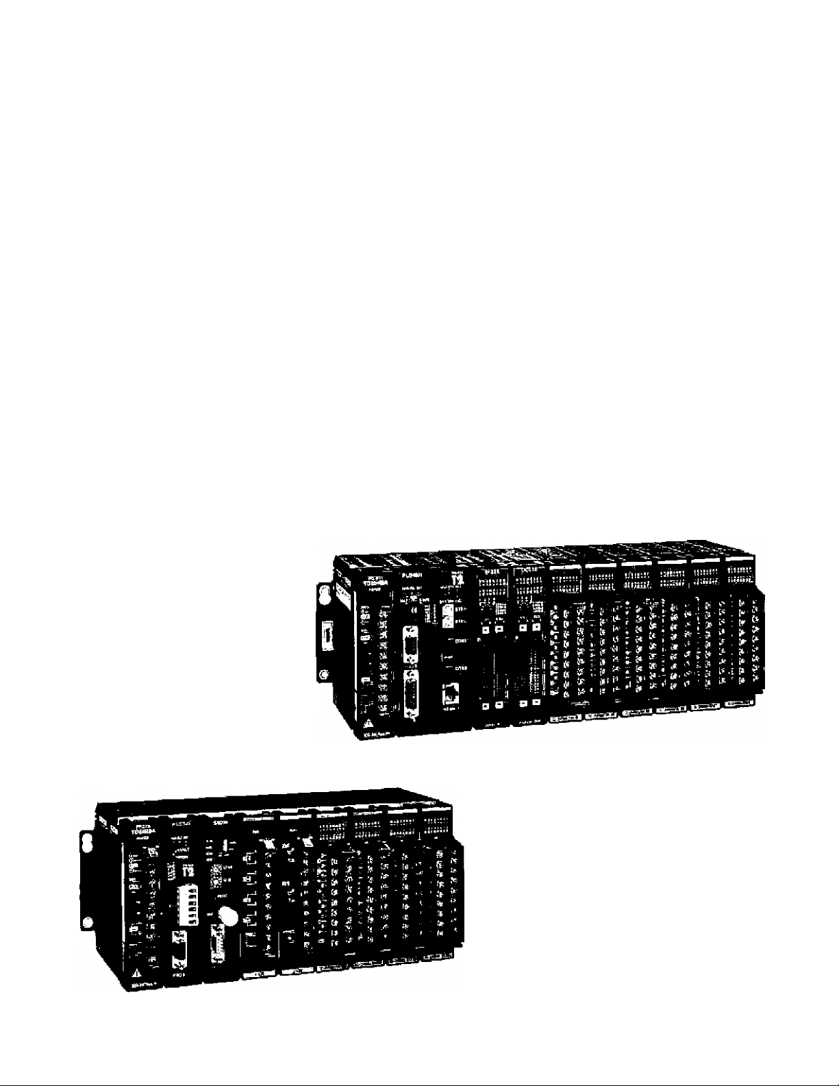
PROSEC T2E/T2N
Small, Powerful Modular Style
Programmable Controllers
Toshiba’s T2E/T2N are small, modular type programmable
controller suitable for both relay replacement and
complex control applications. The T2E/T2N are
2nd generation T2 CPUs. The T2ETT2N
provide afunctional, economical, and
compact solution to a wide range
of OEM and user applications
in automotive, machine
control, and process
control systems.
T2N
Local I/O: Max. 2048 points
Program: 23.5 k steps
Speed:
0.33 ps/contact
1.2 ps/transfer
Local I/O: Max. 1024 points
Program: 9,5 k steps
Speed: 0.33 ps/contact
1.2 ps/trarsfer
Page 3

Key Features
High speed processing
The Т2ЕЯ2Ы excels at applicartions where high speed
processing is required.
• 0.33 ps/contact • 0.44 ps/coii
• 1.2 ps/16*bit transfer • 1.63 ps/16*bit addition
Advanced instruction set
The T2E/T2N offers 24 basic relay-ladder instructions
and 192 function block instructions, including the
following.
• Arithmetic operation • Data manipulations
• Trigonometric functions • PID/ramp/intsgral
• Subroutine call • For-Next loop
• Averaging/filteiing • ASCII ** Hex conversion
• Floating-point math
Two programming Languages
The T2E/T2N supports two programming languages:
Ladder Diagram {LD) and Sequential Function Chart
(SFC). By selecting the appropriate language, or
coinbination of the two, program developrrtent time
can be greatly reduced.
Built-in clock/calendar
TheT2E/T2N has a real-time-clock/catendar function
(year, month, day, week, hours, minutes, seconds)
that can be used for performing scheduled
operations, data gathering with time stamps, etc,
Ethernet connection (T2N|
The T2N CPU modules (PU235N and PU245N) have
built-in Ethernet interface (10BASE-T). Through the
Ethernet, the T2N can communicate with higher level
controllers (computer, workstation, etc.) or other
PLCs with Ethernet.
High speed industrial LAN
The T2E/T2N can be connected to Toshiba’s high
speed industrial LANs (Local Area Networks)
TOSLINE-S20 and TOSLINE-FIO. Tbe TOSLINE
series are suited for real-time control data linkage.
Through these networks, the T2E/T2N can exchange
data with other Toshiba equipment, such as the
TOSDiC CIE system, other T-sehes PLCs, Large
Adjustable Speed Drives, General Purpose Inverters,
etc.
The T2N CPU module PU245N has the TOSUNES20LP (Loop version) built-in into the CPU module.
The TOSLINE-S20LP is a high-ral¡ability double-loop
fiber optic S20 rtetwork.
Device Net
A DeviceNat scanner module Is avalable for the
T2E/T2M. The DeviceNet scanner module can
read/write data to any other manufacturer's ODVA
certified devices (I/O blocks. Inverters to include
Toshiba’s G3, air valve manifolds, sensors, etc.).
Flexible serial port
Password protection
The T2E/T2N can be programmed with one of four
selectable protection levels.
• Level 1: No protect (normal)
• Level 2: Wrlting/moditying program prohibited
• Level 3: Level 2 plus viewing program prohibited
• Level 4: Level 3 plus writing data prohibited
Battery-fess operation fT2E)
The user-program is saved in a built-in Flash
memory. No battery maintenance is required.
The T2En-2N has RS-232C or RS-485 serial
communication port, (It is optional in the T2E)
Using this port, one of the following communication
modes can be selected.
• Computer link mode: Connection with higher level
computer, MMl/SCADA system, modem, etc.
• Data link mode: Easy data linkage between two
T2Es, T2Ns, T2E—T2N or T2E/T2N—Super T1.
• Free ASCII mode: Active communication between
serial ASCII devices, (bar code readers, etc.)
Programmer port function
The T2E/T2N*s RS-232G programmer port supports
the T-series computer link protocol. This allows easy
connection to a higher level computer, an operator
interface unit, a modem, etc.
Page 4
System Configuration
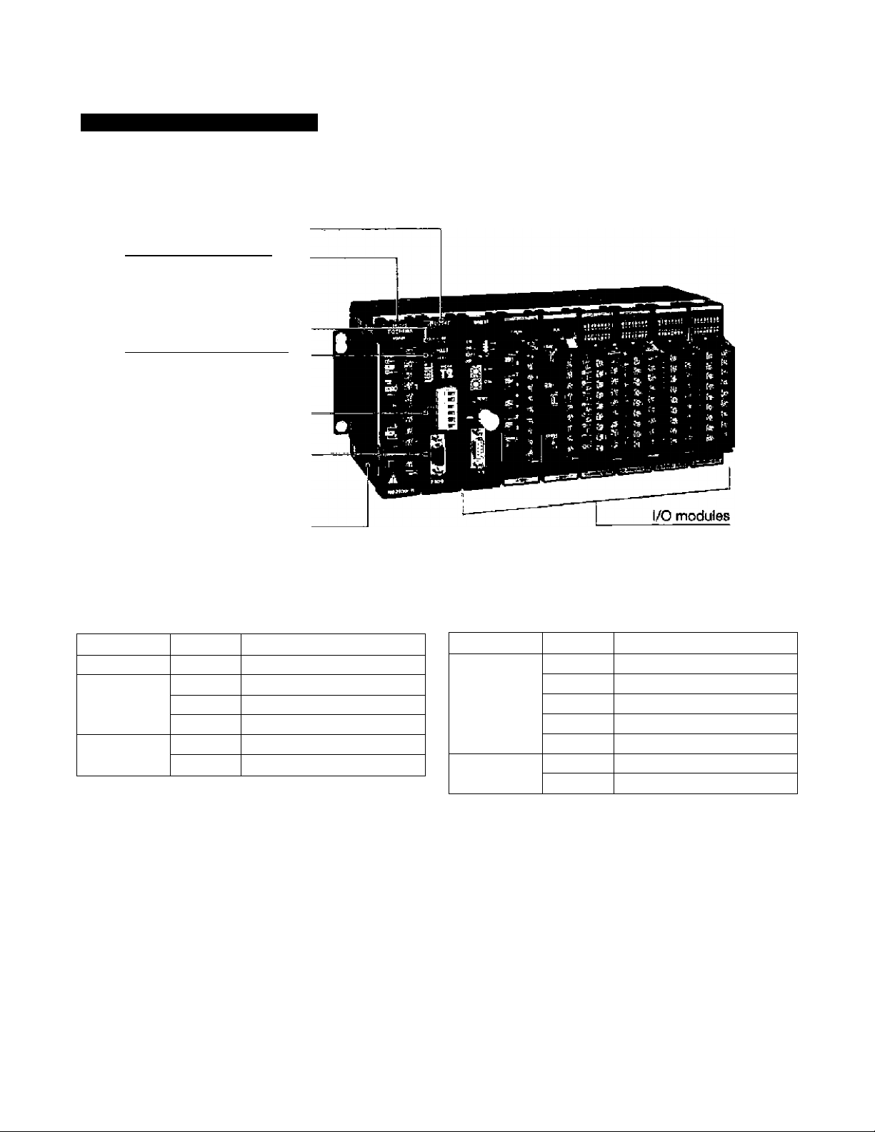
T2E CPU Unit Configuration
CPU module
Power supply module
CPU status indicators
Operation nKJde switch
Optional communicatliMi port
(Add-on option card,
RS-2^C or RS-4S5)
Programmer port (RS-232C)
_______
Rack
T2E basic components
item Type
CPU module
CPU add-on
option card
Power supply
module
PU234E
CM231E
CM232E RS-232C port, w/ battery
BT231E
PS261 100 to 240 Vac
PS31 24 Vdc
Description
9.5 k steps, clock/calendar
RS-48S port, w/ battery
Battery card
Item
CPU rack BU218
Expansion
rack
• The CM231E and the CM232E are optional communicatlcMi cards for T2E. These cards also have the optional
battery mounted on them.
• The CM231E has a terminal block for RS-435 interface. The CM232E has a D-Sub 9-pin (female) connector for
RS-232C interface.
• The BT231E is a card that has only the optional battery.
Type Description
8 irO slots, expandable
UBB2
UBBl
UBA2
UBAI 4 I/O slots, non ej^ndable
BU2E8 8 I/O slots
BU2&6
7 I/O slots, expandaUe
4 I/O slots, expandable
7 I/O ^ots, non expandable
6 I/O slots
• The T2E CPU module can hold only one option card: CM231E, CM232E or BT231E.
• The UBA1 and the U8A2 are stand-alone CPU racks, expansion racks can not be connected.
• The UBBl and the UBB2 can be used as either CPU or expansion racks. When the UBB1 or UBB2 is used as
expansion rack, only one expulsion rack can be connected.
• The BU266 and the 6U268 can be used as either CPU or expansion racks. When the BU2B6 is used as CPU
rack, (t has 5 I/O slots. When the BU268 is used as CPU rack, it has 7 I/O slots.
Page 5
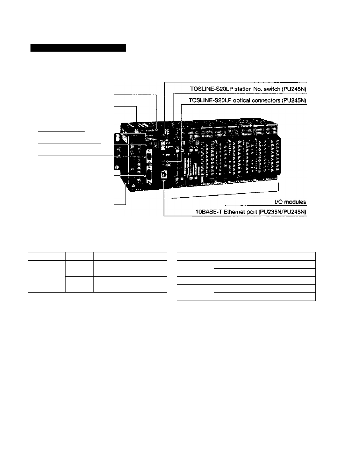
T2N CPU Unit Configuration
CPU module
Power supply module
Network status indicators (PU235N/PU245N)
CPU status indicators
_________
Operation mode switch
Programiner port (RS-232C]
RS-232C/RS-4S5
communication port
_____
Rack
T2N basic components
Item Type Description
CPU module
PU215N
PU236N
PU245N
23,5 k steps, standard type
Standard ptua Ethernet
Standard plus Ethernet
and TOSL1NE-S20LP
Item
Power supply
moduie
CPU rack BU228N 1 8 I/O slots
Expansion
rack
Type Description
PS261 j 100 to 240 Vac
PS31 1 24 Vdc
BU268
BU266 5 I/O slots
8 I/O slots
• The RS-232C/RS-485 communication port (D-Sub 15-pin femaie connector) is built-in the T2N CPU module.
The interface, RS-232C or RS-485, is selected by the switch provided on the CPU module. This port has the
same function as the optional communication cards (CM231E or CM232E) on the T2E CPU.
• The PU235N has all the PU215N functions plus Ethernet (10BASE-T) interface.
• The PU245N has all the PU215N functions plus Ethernet (10BASE-T) interface and the TOSLINE-S20LP
interface,
• Each T2N CPU module comes with a battery,
• The T2N CPU module can be mounted only in the BU228N rack.
• The BU266 and the BU26B can be used only for the expansion racks with the T2N.
Page 6
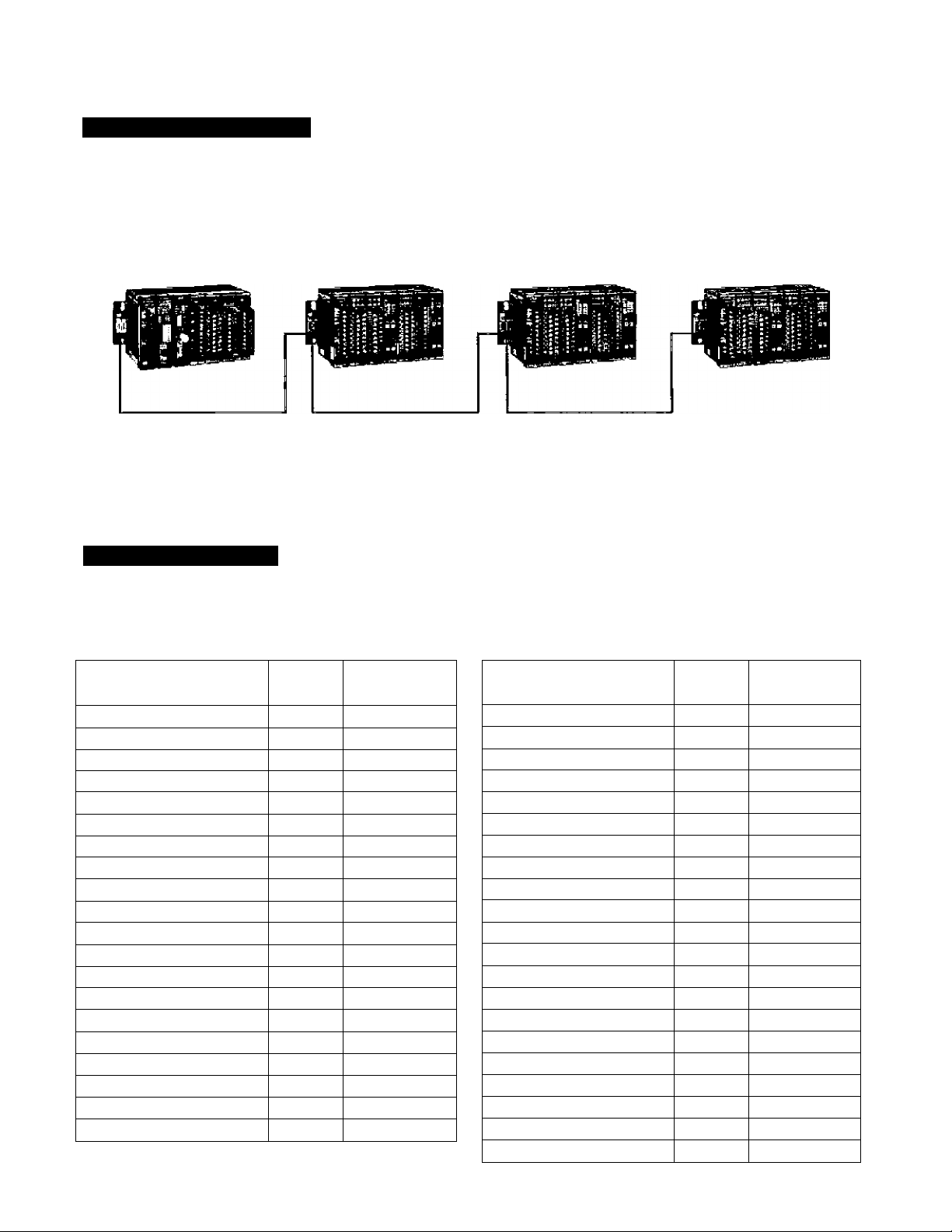
Expansion Configuration
up to three expansion racKs (BU266 or BU26S) can be connected to the T2&T2N CPU rack. In the maximum
configuration, the T2E/T2N provides 32 slots for I/O modules.
CPU unit
Expansion unit #1 Expansion unit #2
Expansion unit #3
A power supply module is nec^sary in each rack.
' The following expansion cables are ayailable; 30 cm, 50 cm, 70 cm and 1.5 m.
■ The total cable length cannot exceed 4.5 m.
Power Supply Check
The power supply module can output maximum 2,5 A {5 Vdc) to power the Internal logic of the modules. Check
that the internal current consumption of the modules on a rack is less than the 2,5 A maximum.
The list below shows the internal current consumption of each module.
Item ' Type
T2ECPU
T2E optional
communication card CM232E 200 mA or less
T2N CPU
CPU rack tor T2E BU218 50 mA or less
CPU rack forT2N
Expansion rack BU263 60 mA or less
16 points DC input DI31
32 points DC input
64 points DC Input
16 points AC Input
12 points relav output R061
PU234E SOD mA or less
CM231E 200 tnA or less
PU215N SOD mA or less
PU236N
PU245N 2.0 A or less
UBB2 50 mA or iess
UBDI
U8A2 50 mA or less
UBAI 60 mA or less
BU223N SD mA or less
BU266 50 mA or less
DI32 80 mA or less
DI235 100 mA or less
IN51
IN61 15 mA or less
Internal 5 Vdc
oonsumptÈon
1.5 A or less
50 mA or less
15 mA or l^s
15 mA or less
50 mA or less
Item Type Intanai 5 Vdc
consumption
8 points relay output R062
16 points transistor output D031
D0233P
32 points transistor output D032 250 mA or less
04 points transistor output
12 points trtac output AC61 300 mA or less
4 chantieis analog input
2 channels analog output
1 channel pulse input
1 axis position control
Communication interface CF211
TOSLINE-S20 (coaxial)
TOSLINE-S20 (optical) SN222A 700 mA or less
TOSLINE-F10 (master) MS211
TOSLIME-F10 (remote)
DevIceNet scanner
D0235 250 mA or less
AI21
AI31 50 mA or less
AI22
AÌ32
A031 70 mA or leas
A022 170 mAor less
A032
PI21 80 mA or less
Mcn
SN221 600 mA or less
RS211 60D mA or less
DN211
40 mA or less
60 mA or less
60 mA or less
50 mAor less
50 mA or less
50 mA or lass
170 mAor less
200 rnA or less
550 mA or less
600 mA or less
500 mA or less
Page 7
Flexible Serial Port
Programmer Port
The T2E/T2N’s RS-232C programmer port supports the open T-sprles computer linK protocol as well as the
proprietary programmer protocol. This próvidas an easy connection to a higher level computer, an operator
interface unit, a modem, etc.
Interface RS-232C
Transmission system Half-duplex
Transmission speed 36D0 bps
Framing Start bit: 1 bit
Data bits; B bits
Parity: Odd or none
Stop bit: 1 bit
Protocol
Computer (ink protocol.
Programmer protocol
Operator interface
^
_____
I .
IlwHiKilKIjEr
T2BT2N
Master computer
Telephorre lirve
Modem
Modem
T2BT2N
Communication Port on the CPU Module
The RS-232C or RS-485 multi-purpose communication port is standard on the T2N CPU. The interface is
selected by a DIP switch.
The RS-232C or RS-4S5 multi-purpose communication port is an option on the T2E CPU. A CM231E or
CMI232E card must be mounted in the T2E CPU module.
By using these communication port, one of the follow'lng three communication modes is available.
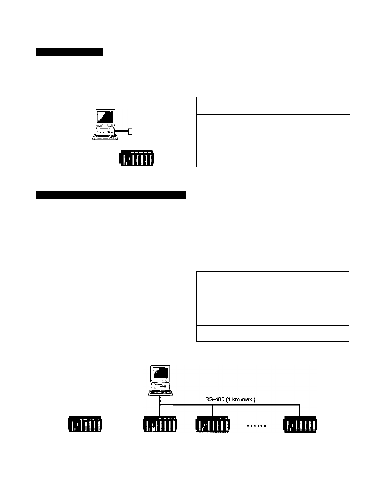
Computer link mode
T-sertes computer link protocol can be used in this
mode. When the RS-485 is used, a maximum of 32
T2E/T2NS can be connected to a master computer.
By using this mode, all the T2E/T2N's data can be
accessed by a master computer.
The T-series PLC programming software fT-PDS}
can also he used in this configuration.
Transmission system
Transmission speed
Framing
Protocol Computer link protocol,
Half-duplex
300/600/1200/2400/
4800/9600/19200 bps
Stsfl bit: 1 bit
Data bits: 7 or 6 bits
Parity: Odd/ewen/none
Stop bit: 1 or 2 bits
Programmer protocof
Master computer
Waster computer
RS-23X {15 rr max.)
T2E/T2N T2&T2N T2E/T2N
T2BT2N
32 T2E/T2t4s max.
Page 8
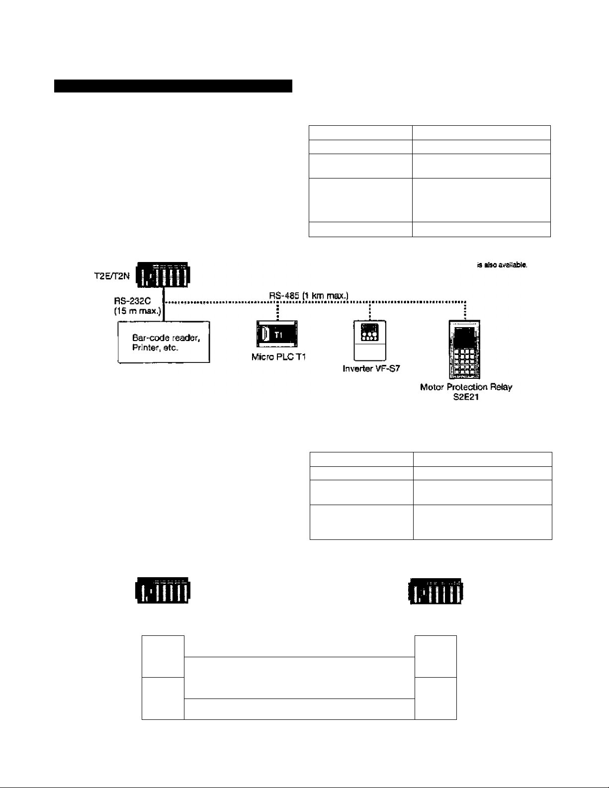
Communication Port on the CPU Module
Free ASCII mode
User defined ASCII messages can be transmitted
and received through this port. A termini, printer,
bar-code reader, or other serial ASCII device can be
directly connected.
Шз mode allows the T2E/T2N to communicate with
other PLCs 0Г1, T2E. T2N. etc.). Inverters (3uch as
VF-S7/A5, G3), or Motor protection relays (S2E21).
Transmission system
Transmission code ASCII
Transmission speed
Framing
Message (ength
Half'duplex
300/600/1200/2400/
4800/9600/19200 bps
Data bits: 7 or B bits
Parity; OdcVeven/nofie
Stop bit; 1 or 2 bits
512 bytes max.
bit; 1 bit
Mete) RS-A^B5 2-wirs sy^sm
Data link mode
Two PLCs (any combination of T2E, T2N or Super
T1-40) can be directly linked together. This direct
link is inexpensive, easily configured and requires no
special programming. File registers FOOOO to F0Q31
are used for the data transfer.
T^E orT2N
RS-232C (15 m max.)
RS-485 (1 l«n max.)
Station No.1
FO^
FOOIS
F0016
F0031
Transmt^ion speed
Protocol Special
Link data capacity
Link data update time
19200 bps
16 words (station 1 to 2)
16 words (station 2 to 1)
approx. 50 ms
(not synchronized with
T2E/T2NS scan)
T2EorT2N
Station No,2
FOOOO
F0015
F0016
F0031
Page 9

Networks
Network Configuration
Hjgh^-l^ve! gpinpLiter/worKstatiari
Remote I/O
Field Intelligent Station
FIS
Any ODVA
certified
devices
Ptes« EBB current
ODVA catatoc) for a
complete listing of
Industrial davIcM from
other morujlociures.
Page 10

TOSUNE-S20/S20LP
ThG T03LINE-S20/S20LP is an N-to-N high-speed data link network. Implicit token passing avoids tho
possibility of message collision. The TOSLINE-S20/S20I_P Is ideal for real-time control between PLCs, or
between PLCs and Toshiba Adjustable Speed Drives.
TOSLINE-S20LP
The TOSÜNE-S20LP is a high-neliabilHy double-loop
fiber optic system. The T2N CPU module {PU245IM)
has the TOSUNE-S20LP built-in.
The double-loop configuration and the floating
master function allow the TOSLINE-S20LP to
continue data link operation even if a transmission
cable is cut or a Station drops out of the network,
TOSLINE-S20
The TOSLINE-S20 is a bus type data link network.
The transmission media can be either co-axial or
fiber optic cable, according to the application
requirement.
• SN221: Co-axial cable type station for T2E/T2N
• SN222A: Fiber optic type station for T2E/T2N
These station modules can be mounted in any PO
slot, main or expansion rack, of a T2E/T2IM system.
11^ TOSLINE-S20LP TOSLINE-S20
Topology Double loop Bus
Access method Implicit token passing |
Transmission speed 2 Mbps
Transmission cable Fiber optic cable (H-PCF 200/230 pmj Coaxial cable (5C2V) or
Fiber optic cable (Gl 50/125 pm)
klax. trarrsmisslon distance Fiber optic: 1 km (between stations)
System total: 3P km
Wax, number of stations
Communication service Sear transmission
Message transmission
Scan transmission capacity 4096 words 1024 words
Scan data update time
Transmission error check CRC
Pstfameter setting tool TOSLINE-S20/S20LP Loader System (S-LS)
Connectable device PLC (T3H and T2N),
61.4 ms/4096 words £5 ms/1024 words
(software runs on Windows 95)
Process control station (PCS),
Industrial computer
Coaxial cable: 1 km (cable total)
Fiber optic: 1 km (bet'^reen stations}
System total: 10 km
64 stations
PLC (T3H, T3, T2N, T2E and T2),
Process control station (PCS),
Industrial computer,
Plant drive (p/S series),
Inverter (VF-A5, G3)
-n.- „.I?
N«ej In the T£N, Itie TOSLINE-SSO (s accessed by READ
and WRÍTE ËnalructionH.
10
Remote Programmlng/monitoring through TOSL)NE-S20yS20LP
TOSUNE-S20/S20LP
T2&T2N
Programming system fT-PDS)
Page 11

Ethernet
The T2N CPU modules (PU235N and PU245M) have
a built-in Ethernet interface (10BASE-7).
Through Ethernet, the T2N can communicate with a
computer, a workstation, or another T2N,
1. T'Senss computer link protocol
Ccmputer/workstatlon
Request
Response
T2N
2. T-series PLC link protocol
Send/receive
T2N
3, Socket inti i
Cwnputer/workstalion
T2N
item
Interface
Media access method
Modulation method
Topotogy
Transmission speed 10 M bps
Distance between nodes
Segment length
Connector
Cable
Communication service
The Ethernet is cenCrelhed by T2N's SEND
end RECV Instructibne.
PU235N / PU245N
10BASE-T
CSMA^CD
Base-band
Bus
200 m max. (with 1 HUB)
1700 m max. (with 4 HUBs)
100 m max. (Node to HUB)
8-pin modular (RJ-45}
Twisted-pair ¡26 to 22 AWG)
Computer link protocol
T-ser!es PLC link protocol
Socket interface (fi ports)
iplL
UniD
DeviceNet
DeviceNat is an open standard field network. Many
DeviceNet compatibie products {ODVA certified) are
available from other manufactures.
The DN211 is a DeviceNet scanner module for the
T2E/T2N. The DN211 can read/write data to any
other manufacturer’s OVDA certified devices, such
as I/O blocks, Inverters including Toshiba's G3, air
valve manifolds, sensors, etc.
Note! The DN211 I» accessed by T2E/T£N's READ
and WRITE instriJctinnE.
T2N
Item
Topology
Number of slaves
Transmissiofi speed
Media access method
Modulation method
Transmls^on distance
(Trunk line)
Max. drop length
Max. total drop length 156 m
Scan I/O capacity
Function
Number of DN211
on a T2E/T2N
Thick 500 m
Thin
DN211
Bus
63 max.
125 k, 250 k. or 500 k bps '
CSMA/NBA
Base-band
125 k 250 k
tOOm
6 m 6m
Input; 128 words/2048 pts
Output; 128 words/2a48 pts
Slave parameter setting
1 from T2&T2N
■Bit strobe
• Peeling
• Change of staie/cyclic
Limited only by power capacity
500 k
250 m
100 m 100 m
73 m 39 in
100 m
6 m
11
Page 12

TOSLINE-F10
The TOSLINE-F10 isaiield network suitable forsm^l distributed I/O systems. Data link between T-series PLCs
is also available. TheTOSUNE-F10 Is extremely easy to setup compared to other field networks.
For the T2E/T2N, two types of TOSUNE*F10 station modules are available.
•MS211: Master station for T26T2N
• RS211: Remote station for T2E/T2N
These station modules can be mounted in any I/O slot, main or expansion rack, of a T2E/T2N system.
Item TOSLINE-F10
Topology Bus
Access method
Transmission speed
Transmission cable
Max. Irartsmisslon distance 750 kbps: 0.5 km (total)
Max, number of stations
Communication service Scsn transmission
Scan transmission capacity 32 words
Scan data update titne
Transmission error check
Connectabie device PLC fT3H/r3. T2N/T2&T2 and T1),
Poltng/selecting
750 kbps or 250 kbps (selectable)
Twisted pair cable (1.2 mmT
250 kbps: 1 km (total)
32 stations
7 ms/32 words (750 kbps)
12 ms/32 words (250 kbps)
CRC
Remote I/O block,
Inverter (VF-A5, G3)
T2N (MS211:(naster)
I m ■
Tt-40
Remote I/O Block Specifications
ttem DI633
Module type
Input voltage 24Vdc. +10/-15%
Min. ON voltage
Max. OFF voltage 3.5 V
Input current 10mA(at24Vdc)
Input points 16 points {16/common}
ON delay
Power vottage 24Vdc.+10/-15%
DC Input (Dry contact input)
9.6 V
10 ms or less
15 ms or (essOFF delay
T1-40
JkIsHL sJiiiii
T2E Remote 1/0
(RS211: remote)
Item ROS63
Module type Relay output DC output
Output voltage
Load current
Output points
1 ON delay 10 ms or less 1 ms or less
; OFF delay
Power voltage
Wh«nVF-AS tsconwcied,
art least ore Semote Input
blocic with kMraret^fon
edOreea mud bo corMto:rted.
Remote I/O
Inverter VF-A5
D0633
24 Vdc, +20% /
240 Vac, +10% (max.) +10/-20%
2 A/point (resistive)
4 A/commcm 4 A/common
16 points (4 X 4/eQinmon)
10 ms or less
24 Vdc. +10/-15%
12 to 24 Vdc,
1 A/point,
15 points (16/common)
1 ms or less
12
Page 13

Programming Tools
T-series Compatible
The HP911 Handy Programmer and the T-PDS (T-series Program Development System) software program the
entire family of T-seri^ programmable controllers. Programming instructions are upward compatible in the
T-series controllers.
Vi-**- • -M: I’?™ I
i-s f
Handy Programmer
Program Storage Module RM102
The HP911 is a hand-held graphic programmer. Its portability makes
it Ideal for maintenance use at remote locations. The HP911 has all
the features of a full size programming terminal. (2 m cable for
connecting T2E/T2N is included!)
• Ladder logic programming of T-sahes programmable controllers
T1,T2, T2E. T2N andT3.
(SFC programming/monitoring is not possible)
• Built-in EEPROM allows program copy between T-series confrollers.
• Two display modes,
' Normal: 5 lines and 12 columns
- Zoom; Full device description
• Data monitor for I/O and internal registers.
• On-line data set & I/O force.
• Backlit LCD display for better operation in dim light.
The RM102 is an external memory, which can storeaT2Eor aT2N
program. By using the RM102, program saving from theT2E/T2N to
the RM102, and program loading from the RM102 to the T2E/T2N can
be done without need of a programmer.
Because the RM102 has an EEPROM, maintenance-free program
storage and rapid saving/loading can be done.
Nols) To connect the RM102 lo Ihs TSETTZM, an adaplei te oacassatv.
13
Page 14

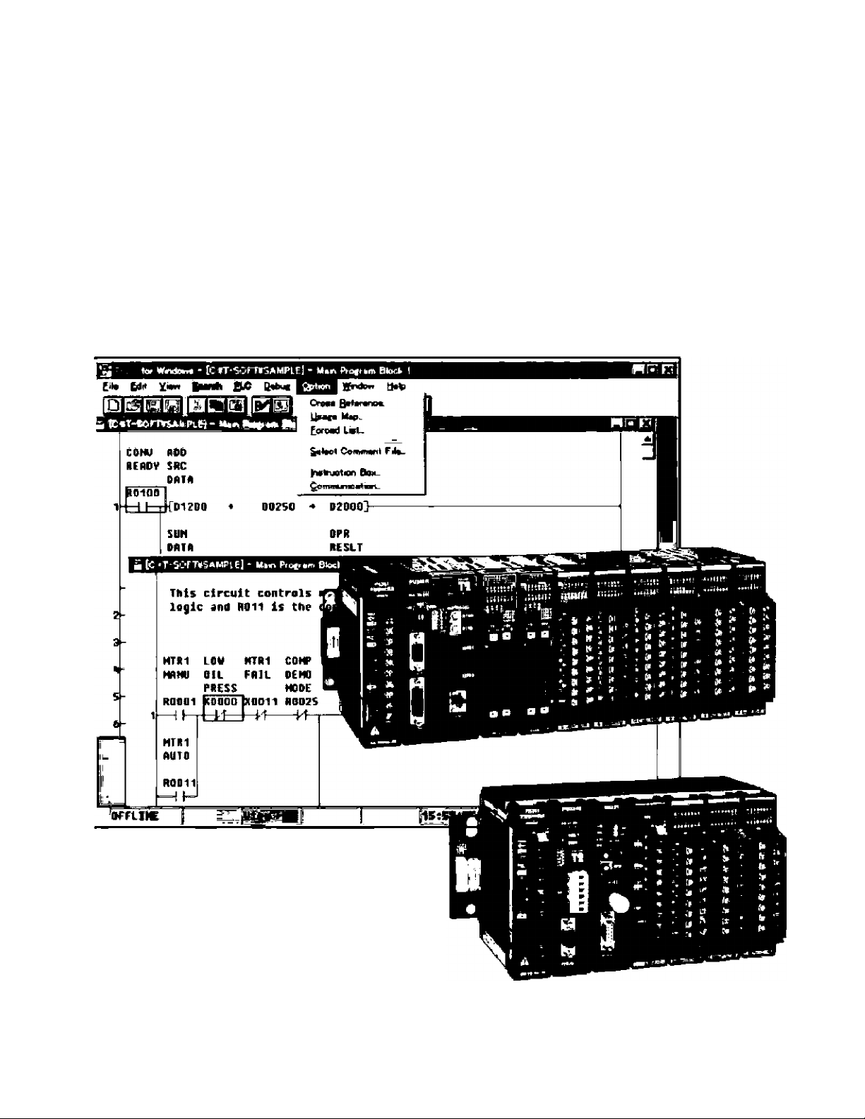
T-series Program Development System (T-PDS)
The T-series Program Development System (T-PDS) is a software program that runs on any Toshiba's Notebook
computer or other IBM-PC compatible personal computer. The T-PDS software supports on-line/off-line
programming, debugging and program documentation for all T-series programmable controllers; T1, T2, T2E,
T2N, T3 and T3H.
The T-PDS software has;
^ A full-feature program edition that includes cut & paste,
search & replace, insert, delete, etc.
• Group programming and block merge,
• Load, save and compare programs between disk file and CPU,
• Monitor power-flow status of on-line ladder program
and register values.
• Sampling trace screen useful for system checking.
• Disable inputs and force colls ON or OFF from keyboard.
• Document programs with commentary.
• Print map options such as register values, register/device
usage, full cross-reference, etc.
• Built-in Modem initialize and Dial-up.
<Dl» fOli>
•lie* will
ti» I *
-\Y
-----------
*-
i--1*1
„«J,
-----------------------------------------
—1 i
NISI
-------
I'f-i
-------------------------------
--------------------------------
Program edit screen
mot-jt i j m Ln E3 frs' □ ftn ra
-DH i—if '
'
riMA ;
Jl»l [
(
f4l»M
BMK1
□
»* n
\ J
__
HIP y
HI
---------
W1 J4il IIT «Ml
{■«r? m* MaMUMii» WY »ii»0
-C>MM* « - ai»f')iMKQ-
Hi-'MBB IIP aizM >
lAlttl Jj:
t
m
i
g2B3
E&DO
^SBn
•im
—»1—1 cm I--1 «Ml p.
<«IPI
_iM__________
I {potK HioD -* ifaa^
_
j« »«I
i
-ftaw- ■
»<1 C
n
i
Hk1 >«{11
4 , a A p ¡fMlfi *17411
Program execution monitor (Ladder)
14
Program execution monitor (SFC)
Page 15

Instruction Set
Basic Instructions
FUN ^^o.Symbol Name
-I l-
-l/l-
-lîl-
-Ul-
-( )-l
•( H
-III- Inverter
-{IH
-I PI-
-INI-
-(PH
-<NH
JCS Jump control set
JCR
TON
TOF
SS
1 CNT
MCS
MCR
134 MCSn
135
148 TRG
MCRn
END End
N0 contact
NC contact
Transitional contact (rising edge)
Transitional contact [falling edge)
Coil
Forced coil (debugging purpose only)
Invert coil
Positive pulse contact
Ne^tlve pulse contact
Positive pulse coil
Negative pulse coil
Jump control reset
On delay timer
OFF delay timer
Single-shot timer
Counter
Master control set
Master control reset
Master control set (nesting)
Master control reset (nesting)
Timer trigger
Data transfer Instructions
FUN No, Symbol
IS MOV Data transfer
19 OMOV Double-word data transfw
20
21
22 XCHG Exchange
23 DXCH
24 TINZ
25 TMOV
26 TNOT
90
91 DPX Demultiptexer
92 TBM
93
NOT ^ Invert transfer
DNOT
MPX Muttiplaxer
BTM
Double-word invert transfer
Double-word excrtange
Table initialize
Table block transfer
Table invert transfer
Table -* bit transfer
Bit — table transfer
Name
Arithmetic Operations
FUN No.
27 + Addition
28
29
30
31
32 D-
33 D*
34
35 +C
36 -C Subtraction with carry
37
38 0-C
39
40 u/
41 DIV UnsigrMd double/single division
43 +1 Increment
44
45
46 D-1
Symt)ol
-
«
/ Division
D+
0/
O+C
u*
D+1
Subtractkjfi
Multiplication
Double-word addition
Double-word subtraction
Double-word multiplication
Double-word division
Addition with carry
Double-word addition with carry
Double-word subtraction with carry
Unsigned multiplication
Unsigned division
Daubte-word increnrent
-1 Decrement
Double-word decrement
Name
Logical Operations
FUN No.
46 AND AND •
49 DANO Double-word AND
50
51 DOR
52 EÓR Exclusive OR
53
54
55
57 TAND
58 TOR Table OR
59 TEOR
60
64 TEST Bit test
65 DTST Double-word fait lest
66
Symbol
OR
DEOR Double-word exclusive OR
ENR NOT exclusive OR
DENR
TENR Table NOT exclusive OR
TTST Bit lile bit test
OR
Double-word OH
Double-word N07 exclusive OR
Table AND
Table exclusive OR
Name
Shift Instructions
FUN No,
68
69
70
71 SHLn n Pits shift left
72 TSHR Bit (its n bits shift right
73
74
75
76
Symbol
SHR1
SHL1 1 bit shift left
SHRn
TSHL
SB
DSR
SFT Device shift
1 bit shift right
n bits shift right
Bit file n bits shift left
Shift register
Bi-directional shift register
Name
15
Page 16

Rotate Instructions
Special Data Operations
FUN No.
70
79
80
81
82
83
84 RRC1
87 RLCn
Symbol
RTR1
RTL1 1 bit rotate left
RTRn n bits rotate right
RTLn
TRTR Bit file n bits rotate right
TRTL Bit tile n bits rotate left
85 RLC1
85
B8 TRRC
B9 TRIG
RRCn
1 bil rotate right
n bits rotate left
1 bit rotate fight with carry
1 bit rotate left with carry
n bits rotate right with carry
n bits rotate left with carry
Bit file n bits rotate right with carry
Bit tile n bits rotate left with carry
Comparison Instructions
FUN No. Symbol
35
96 >
97
98
99
100 <
101 <=
102 D>
103 0>=
104 D= Double-word equal
105
106 0<
107 D<=
108
109 U>=
110 U=
111 Uo Unsigned not equal
112 u< Unsigned less than
113 u<=
TCMP Bit file comparison
Greater than
>=
=
<> Not equal
Do Double-word not equal
Greater than or equal
Equal
Less than
Less than or equal
DouWe-worct greater Uian
Double-word greater than or equal
Double-word less than
Double-word less than or equal
U> Unsigned greater than
Unsigned greater than or equal
Unsigned equal
Unsigned less than or equal
Special Data Operations
FUN No. Symbol
114 SET
115 RST 1 Device / register reset
116
117 TRST
118 SETC Set carry
119 RSTC
TSET Table bit set
Device / register set
Table bit reset
Reset carry
Name
Name
Name
FUN No.
120 ENC
121 DEC
122
123 DBG
124 SCH
125
126
127 POPF Pop first
147
149 U/D
Symbol Name
Encode
Decode
EC
PUSH Push
POPL Pop last
F/F Flip flop
Bit count
Double-wtKd bit count
Data search
Up / down cDurrter
Program Control Instructions
FUN No. Symbol Name
128 CALL
137 SUBR
129 RET
130
136 LBL
132 FOR 1
133
138 STOP
140 El Enable interrupt
141 Dl
142
143 WDT
144 ST!Z
145
241 SFIZ
JUMP Conditional jump
NEXT
I RET Interrupt return
SUN
STOT
146
158
159
□RUM Drum sequencer
GAM
Subroutine call
Subroutine entry
Subroutine return
Jump label
FOR-NEXT loop (FOR)
FOR-NEXT loop (NEXT)
Program execution stop
Disable interrupt
Watchdog timer reset
Step sequence Initialization
Step sequence input
Step sequence output
Cam sequencer
SFC initialization
RAS Functions
FUN No. Symbol
150
151 DIAR
152 STLS
153 STLR
154 CLND
155 CLDS
DIAG
Diagnostic display
Diagnostic display reset
Status latch set
Status latch reset
Calendar set
Calendar operation
Name
16
Page 17

Functions
BCD Operations
FUN No. SymboE
56 MAVE
61
160 UL
161
162 MAJÍ
163 MIN
164
165 FG
166 DB
167
168
169 RAMP
170
171 PID2
156
172
173 eos
174 TAN
175
176 ACOS
177 ATAN
178
179
DFL
U. Lower limit
AVE Average value
RT Square root
INTG Integral
PID
PI03
SIN Sine function
ASIN
EXP
LOG Loganthm
Moving average
Digital lillar
Upper limit
Maximum value
Minimum value
Funciron generator
Dead band
Ramp function
PID Iproportional integral derivative)
Deviation square PiD
Pre-derivative real PID
Cosine function
Tangent function
, Arc-sine function
Arc-cosine function
Arc-tan gent functiori
Exponential function
Data Conversion Instructions
FUN No, Symbol
62 HTOA
1 ^
180
181 DABS
182 NE6
183
184 DW
ias 7SEG
185 ASC
1S8
189 DBIN
190
161
ATOM
AES
DNEQ
BIN
BCD
DBCD
HEX to ASCII conversiwt
ASCII to HEX conversion
Absolute value
Double-word absolute value
Two's complem^t
Double-word two's ccffnplement
Double-word conversion
7-BegfTierTt decode
ASCII conversion
BCD to binary conversion
Double-word BCD to binary conversion
Binary to BCD conversion
Double-wOrd binary to BCD conversion
Name
Name
FUN No. Symbol
192 B+
193 B- ^
194 B+
195
196 DBi197 DB198
199 DB/
200
201
202
203
B/
DBv
B+C
B-C
DB+C
DB-C
BCD addition
BCD subtraction
BCD multiplication
BCD division
Double-word BCD addition
Double-word BCD subtraction
Double-word BCD multiplication
Double-word BCD division
BCD addition with catty
BCD Subtraction with carry
Double-word BCD addition with carry
Double-word BCD subtraction with
1 carry
Floating-Point Instructions
RJN No.
204 FLT
205 FIX
208
209
210 F*
211
212 F>
213 F>=
214
216 " F<
217
Symbol ■ Name
1
F-+ 1 Floating-point addition
F- Floating-point subtraction
F/
F-
215
F<>
F<= ' Floating-point less tnan or equal |
Fixed-point to floating-point
conversion
Floating-point to fixed-point
conversion
Roating-point multiplication
Floating-point division
Floating-point greate" than
Floating-point greater than or equal
Floating-pCHPt equal
Floating-point not equal
Floating-point less than
Special I/O Instructions
FUN No.
237 READ
Symbol
236 I/O
236
238
233 SEND
240
XFER
WRITE Special module data write
1 RECV Network data receive
Direct input / output
Expanded data transfer
Special module data read
Network data send
Name
I
Name
17
Page 18

Specifications
Functional Specifications
Item
Control method Stored program, cyclic scan system
Scanning system
I/O processing method
Number of I/O points (locaf)
User
program
Program types
User I/O device/register 1024 pointg/64 words
data (X/Y or XW/YW; batch I/O, (X/Y or XW/YW: batch I/O.
Clock/catendar Year, month, day, day of the week, hour, minute, second
SRAM memory back-up Super capacitor; 3 days/25 "C
Serial communicaiion function Programmer port: (RS-232C): * T-sehes programmer protocol (1 -to-1)
Networks TOSLINE-S20
FIAS Dtagfwals Battery level, I/O bus check, I/O response, I/O registratíon, I/O parity.
Program language
Program capacity 3,5 k steps
Memory SRAM and Flash memory
Iretructions
Execution speed 0.33 ps/contact, 0.44 ps/ccil, 1.2 ps/transfer. 1,G3 ps/addition
Auxillay device/register
Special device/register
Timer device/register
Counter devioe/regisier
Data register
Link device/register
Link reiay/register 4096 points/256 words (ULW) (forTOSLINE-FlO)
RIe register
Expanded file register
Index register 1, J, К (total 3 words)
Retentive memory
Monitoring Event history recxjrd, scan time measurement, others
Debugging
Floating scart or constant scan (interval: 10 to 200 ms, i0 ms units)
Batch I/O (refresh). Direct I/O, or combination
1024 points/64 words
Ladder diagram (relay symbol -к function block)
Sequential Function Chart (SFC)
Basic ladder instructiohs; 24 types
Function instructions: 192 types
1 main program
1 sub-program (initial program)
1 timer interrupt (interua): 5 to 1000 ms, 5 ms units)
256 subroutines
I/O or IW/OW: direct I/O)
204S point3/12S words (R/RW)
4096 points/256 words (S/SW)
256 points fT./T) (TOOO—T063:10 msj 512 points (T./TI (TOOO—Т06Э: 10 ms)
256 points (C/C) 512 points (C7C)
4096 words (D) 8192 words (D)
3192 points/1024 words (2/W)
(forTOSUNE-S20) (forTOSUNE-S20LP)
1024 words (F)
24576 words (accessed by XFER instruction)
User specified range for FtW, T, C and D, and whole F
Battery (option): 5 уеагЕ/25 ”0
Communication port • T-series programmer protocol [1 -to-N)
(RS*4S5 or FIS-232C) • T-series computer link protocol (1 -to-N)
(using optional comms card • Free ASCII communication
in case of T2E) • 32 words data link (between two T2E/T2Ns)
TOSLINE-F10
DeviceNet TOSHNE-S20
watchdog timar, illegal instruction, LP check, others
On-line trace monitor, force, sampling trace, status latch,
single step/rung execution, break point setting, others
T2E T2N
2046 poifTts/128 words
23,5 к steps
204B poinrts/12S words
!/OorlW/OW: direct I/O)
4096 points/256 words (FVRW)
(T084—T255:100 ms) (TD64—T511; 100 ms)
16000 points/2048 words (Z/W)
Battery №>oilt-in}: 5 years/25 X
• T-s0ries computer link protcwol (1-to-1)
Ethernet (10BASE-T)
TOSL1NE-S20LP
TOSLINE-F10
DeviceNet
18
Page 19

General Specifications
Hem
Power supply voltage
Power corisumption
Retentive power Intermption
Insulation re^stanca
Withstand voltage
Ambient temperature
Ambient humidity
Noise (mmunHy
Vibration imniunity
Shock immunity
Standard
External Dimensions
4-05
Specification
100to24t)Vac(+10M5 %), 50/60 Hz
24 Vdc (-t-20/*16%)
53 VA or less (ao power supply)
22 W or (ess (dc power supply)
10 ms or less
10 Mü or more (between power terminals and ground ta'minal)
1500 Vac -1 minutes (between power terminals and ground terminaf)
0 to 55 °C (operation)
-20 to 75 “C (storage)
20 to 90 % RH (no condensation)
1000 V p-p/1 ps, 0a^36rtEC (EMC diractivB)
15.7 Hz - 3 mm p-p (3 mutualty perpendicular axes)
36 m/s’ (10 g) (3 shocks per axis, 3 mutually perpendicular axes)
ÜL/C-UL, CE
BU228N 1
W3 366.0
W2
W1 394.0
360-0 ; 360.0 314.0
BU21S BÜ268 BU265
356.0 300.0 234.0
24S.0 314.0 215.0 314.0
394.0
340,0 274,0 323.0 229.0 323.0
UB82 UBB1 U8A2
300.0 201.0
300.0 201.0
UBAI
215,0
229.0
UrWi mn
19
Page 20

I/O Module Specifications
Digital Input
item DI31 DI32 DI236
Module type
Input voltage 12 to 24 Vdc/ac, +1Q/-15% 24 Vdc, +10/H5%
Min, ON voltage
Max, OFF voltage 3.6 V 6.0 V 5,0 V
Input current
Input points 16 points
ON delay
OFF delay 10 ms or (dc, mode N)
9.GV 18.0 V 16.0 V
6 mA (at 24 Vdc} 5 лпА (at 24 Vdc) 4 mA Cat 24 Vdc)
(16/common) (4 X a/common) (8 X e/common)
10 ms or less (dc, mode N) 10 ms or less (mods N)
1,5 ms or less (dc, mode H)
1.5 ms or less (do, mode H> 1,5 ms or less [mode H)
DC inpurt, current sink/source
32 points 64 points
10 ms or less
1.5 ms or less (mode H)
10 ms or less (mode N)
15 ms or less
Item IN31
Module type AC input
Input voltage
Mln. ON voltage 80 Vac
Max. OFF voltage 30 Vac 60 Vac
Input current
Input points
ON delay 20 ms or less
OFF delay
100 to 120 Vac. +10/15% (60/60 Hz)
7 mA (at 10O Vac)
16 points (16/common)
15 ms or less
200 to 240 Vac, +10/15% (50/60 Hz)
160 Vac
6 mA (at 200 Vac)
Digital Output
Item D031
Module type
Output voltage
Load current 1 A/point (12/24 V)
0,3 A/point (5 V)
1.2 A/4 points
Output points 16 points
(16/common)
ON delay
OFF delay
Leakage current
1 ms Or less 1 ms or less 1 ms or less 1 ms or less
1 ms or less
DC output, current slr>k
Sto 24 Vdc, +10/-5% 5to24Vdc,3:10%
0.1 A/poinI (12/24 V)
0,02 A/point (5 V)
32 points
(4 X 8/common)
2 ms or less
D032 D0235 D0233P
0,1 Apoini (12/24 V)
0,05 A/point (5 V)
64 points
[8 X 8/common)
1 ms or less
0.1 mA or less (at 24 Vdc)
1Ы61
DC cxjtput,
current source
12 to 24 Vdc, ±10%
1 A/point (12/24 V)
1.2 M points
16 points
(16/common)
1 ms or less
Kern
Module type
Output voltage
Load current
Output points 12 points (3 X 4/commoni} 8 points (isolated)
ON delay
OfT delay
Leakage current None
20
Relay contact output, normally open contact
2 A/poInt (resistive load)
4 A/common
R061 R062
24 Vdc, +20% / 240 Vac, +10% (max.) 100 to 240 Vac, +1Q/-15%
2A/point {resistive load) 0,5 A/point
10 ms or less 1 ms or less
15 ms or less 1/2 cycle + 1 ms or less
AC61
AC output
(50/60 Hz)
0.6 A/SSR (2 points)
12 points (3 X 4/роттоп)
1.2 mA or less (at 100 Vac)
3 mA or lass (at 240 Vac)
Page 21

Analog Input
Item
Input range 1 to 5 V / 4 to 20 mA OtolCV 1 to 5 V / 4 to 20 nnA -10 to 10 V
Input impedance
Input channels 4 channels (4Усоттоп)
ResolutlQH e-bft (Oto 250) 12-bit (0 to 4000) 12-bit (-2000 to 2000)
Cwiverslon cycle Approx, 1 ms/4 channels Approx, 9,6 тз/4 channels
Overall accuracy ±1 % (full scale)
1 to 5 V; 500 kn 500 kR or more 1 to 5 V: 1 МП
or more or more
4 to 20 mA: 250 Й 4 to 20 mA; 250 Ü
AI21
AI31 A122 AI32
1 MO or more
±0.5 % (full scale)
Analog Output
Item A031
Output range
Load impedance
Output channels 2 channels (2Усоттоп)
Resolution 8-bit (0 to 250) 12-bil (0 to 4000} 12-blt (-2000 to 20СЮ)
Conversion cycle Approx. 1 ms/2 channels
Overall aocuraoy
1 to 5 V / 4 to 20 mA /
0to5V/0to10V
5 V range: 5 kQ or more
10 V range: 10 kñ or more
20 mA гш^де: 600 Q or less
±1 % (full scale)
1 to 5 V M to 20 mA
1 to 5 V: 5 kQ or more
4 to 20 mA: 600 Й or less
A022 A032
-lOtolOV
S kCi or more
±0,5 % (full scale)
Pulse Input Position Control
Item PI21
Input channels 1 channel (phase A, B, and IVt)
Input voltage
Input current 10rrtA(5V)
CoLnting speed 100 K pps max.
Count data 24-bit binary
Pulse input mode Quuadrature (90“ phase sift),
5/12 V. ±10%/-20%
7.5 mA(12 V)
(-8358608 to 8388607)
Up/do\wn {A: up / B: down)
Communication Interface
item CF211
Interface
Transmission
system
Transmission
code
Transmission
speed
Framing Start bit 1 bit
Message length
RS-232C, 1 port
Full-duplex
ASCII
300, 600.1200, 2400, 4800,
9600, or 19200 bps
Data bits: 7 or 8 bits
Parity: Odd, even, or none
Stop bit: 1 or 2 bits
320 bytes max.
Item MC11
Control axes 1 axis
Control units
Control range ±999,999 (speciRed unit)
Pulse output
speed
Input signals
Input voRage 12/24 Vdc (10mA)
Pulse CKJtput
Output voltage 5 to 24 Vdc (50 mA)
Parameters Acceleration/deceleration rate,
Parameter
backup
Pulse, mm, inch, degree, etc.
200 к pps max.
Zero-marker, over-travel limit,
emergency stop, etc.
CW and CCW,
Pulse and Direction
backlash compensation, etc.
EEPROM
21
Page 22

Ordering Information
Item
T2ECPU moduls
T2E CPU add-on
option card
T2N CPU modjie
CPU rack ForT2E Non expandable
Expansion rack 6 I/O slots
Power supply
I/O module DC Input
Network
9.5 k steps, flash memory, ciock/caJendar
Commuriigation card RS-485, with battery
Communication card RS-232C, with battery
Battery card, with battery
Standard type, 23,5 k steps, flash memory, ctock/calendar,
RS-232CyRS-485 communication port, with battery
Standard type plus Ethernet
Standard type plus Ethernet and TO3LINE-S20LP
Expandable
For T2N Expandable
8 I/O slots
100 to 240 Vac
24 Vdc
16 points, 12 to 24 Vdc/ac. 8 mA
32 points, 24 Vdc, 5 mA (connector type)
64 points, 24 Vdc, 4 mA (connector type)
AC input
Relay output
DC output
AC output 12 points, 100 to 240 Vac, 0.5 A/point
Analog Input
Analog Du^ut
1 channel pulse input, 5/12 V, 100 k pps max.
1 axis position control, pulse train output, 200 k pps max.
Communication interface, RS-232C, 1 port
TOSLINE-S20
TÒSLINE-F10
DeviceNel scanner module tor T2E/T2N
16 pointe, 100 to 120 Vac. 7 mA
16 points, 200 to 240 Vac, 5 mA
12 points, 24 Vdc/240 Vac, 2 A/point
8 points {isolated), 24 Vdc/240 Vac, 2 A/poInt
16 points, 5 to 24 Vdc, 1 A/point
32 points, 5 to 24 Vdc, 0,1 A/pglnt (connector)
64 points, 5 to 24 Vdc, 0.1 A/point (oonrtector)
16 pts, 12 to 24 Vdc, 1 A/point, current source
1 to 5 V/4 to 20 mA, 8-blt resolution AI21
0 to 10 V, 6-blt resolution
1 to 5 V/4 to 20 mA, 12-bit resolution
-10 to 10 V, 12-bit resoluttan AI32
1 to 5 V/4 to 20 mA/0 to 10 V, S-btt rasolution
1 to 5 V/4 to 20 mA. 12-bit resolution
-10 to 10 V, 12-blt resolution
Co-axial cable type station for T2E/T2N
Fiber optic type station for T2E/T2N
Master station forT2E/T2N
Remote station for T2E/T2N
Remote Input block, 16 pc^nls, 24 Vdc
Remote output block, 16 points, relay
Remote output block, 16 points. 24 Vdc
Dew!fiption
Type Part number
PU234E TPU234E*S
CIVI231E
CM232E TCM232EAS
BT2316
PU215N TPU215NT
PU236N TPU235N*S
PU245N TPU245N*S
4 I/O SiOlS
7 I/O siots UBA2 EX10*UBA2
4 I/O slots
7 I/O slots UBB2 EXIO'UBBI
Tiro slots BU218 TBU218«'&
8 I/O slots BU228N TBU228N*S
UBAI EX10*UBA1
UBBl EX10-UBB1
BU266 TBU266«S
BU268 T8U258-*S
PS261 TPS261«S
PS31 EX10*MPS31
DI31 EX10MD131
DI32 EX10*MDI32
DI235 TDI235-rS
IN51
IN61 EX10*MIN61
R061 EXlO^MROei
B062
D031 EXlO*MD031
D032 EX10'MDOS2
D0235
D0233P TD0233P-S
AC61
AI31 EX10-MAI31
AI22
A031 EX10-MAO31
A022
A032 EX10»MA032
PI21 EX1CHMPt32
WC11
CF211 TCF211»-S
SN221
SN222A SSN222AMS
MS211 FMS211AM
RS211
D1633
R0663 FROG63*K
D0633
DN211
TCM231EAS
TBT231EAS
EX10-MIN51
EX10-MRO62
TD023S-S
EXIOtMACei
EX10»MAI21
£X10>MAt22
EX10MA132
EX10*MA022
EX10‘MMC11
SSN221 «MS
FRS211AM
FDI633»K
FD0633-K
TDN211«S
22
Page 23

ttam
Expansion cable
Peripheral tool
Peripheral cable
Misceilansous
0.3 m length
0,5 m length
0,7 m tengUi
1.5 m lerrgth
Programming software
ft-PDS)
Handy programmer with 2 m cable forT2E/T2N
Configuration software for
TOSLINE-S2ftiS20LP (S-LS)
Program storage module
5 m cable for T-PDG or S-LS
Empty slot cover
RS-232Cii^-485 converter
Spare battery
Description Type
CARS
CARS EX10CAR5
CAR7
CS2RF
For MS-DOS
For Windows 3.1/95
For MS-DOS (S20 only)
For Windows 95 (S30/S20LP) S-LS Win
T-PDS TMM33I15S
T-PDS Win
HP911
S-LS SMM23hSS
RM102
CJ905 TCJ905-CS
—
ADP-6237B
—
Part number
EX10-CAR3
EXiO<;AR7
TCS2RFCS
TMW33E1SS
THP911«S
SMW23E*SS
TR!Vlia2r*S
EX10-ABP1
EX25PADPS237B
E!<25SER6
Quality
Quality is a religion at Toshiba. Quality starts at the very basic level, the 1C (integrated circuit), and proceeds
through design development and manufacturing of all types consumer and industrial products.
Toshiba corporation's quality management system in
design, development and manufacturing of
programmable controllers is approved to satisfy the
quality management standard ISO9001.
23
Page 24

Safety Precaution
A
This product la k[l«ntfad to be used tor the control of Irrdiistrtal
laachlndB and proca&ui.
MtauM of this product erm result lit property dninepe or humnn Iplury.
Read related nuinuals earetutly befora using this produoL
PROSEC aird i OSUME are registewcj trademarte of TOSHIBA Cwporatioo.
IBM is S r«$lite<td tredtdidfK of Intsmatioital Bualnasa MBcfilrtaa Oorpamtion.
mS-POS PPd WlndoiMS are registaiad trademarks of Mteroseft Corporailort.
Ettiamet 18 в registeratJ tradem*k at Xera:< Софсгабоп.
DetricaNac is a Iredawark ol ihe Opart DauioeMet Vamiar Assadstlon. Inc.
For further infomiatiop. plaaoe oontaot your reaiecrt Toshipg Rtpresentairvaor
Intantatloral Opanttlarts-Praaijaar Goods.
The data ghreri In this brochure are subjeci to change without nolice.
In Touch with Tomorrow
TOSHIBA
TOSHIBA CORPORATION
lihdustrlal Equipmddt Doparananit
1-1, Snitetda i-chome, Mliraio-ku,Tokyo 105, Japa.n
Tel.: (C3)3457-f900 Fax.; (03)5444-9266
97-11{KS}5527
Toth lb a imtrpaewtfd
Corporation
Industrial Dluislen
Houston U.SA.
Tel,: Т13-466-0г?7
Fa*.; 713-406-3773
Toshiba ipternailcrtai
Corporation (Einopel Lid.
MiddiBSax J.K
T0|,:O16I-756'6OCO
Fax.; 01S1-&4S-4a89
Toshttia International
Corporation Pty.,Ltd.
Sydrery AtisiralHi
Tel.: 02-428-2077
Fax.: [E-r127-7405iB
Toahiba Asie Pacific
Re., Ltd.
Singapore
Tel: 66-324-1046
Fax.: 55-324-5236
Printed in iap^
 Loading...