

Toshiba T2100 Series, T2105 Series Maintenance Manual

1-1
1.1 Features
The Toshiba T2100/T2105 Series computers are one of the lightest and most advanced
portable computers available. Utilizing advanced technology and high-speed components, the
computer offers excellent display legibility, battery operation and IBM PC/AT compatibility.
References to the T2100, T2100CS, and T2100CT models relate directly to the T2105,
T2105CS, and T2105CT models respectively.
The T2100/T2105 Series computer system units consist of the following features:
❑ Microprocessor
The SL Enhanced Intel 486DX2-50 microprocessor operates at 50 MHz, 3.3 Volts.
❑ Math coprocessor
The math coprocessor is stored in the i486DX2 microprocessor.
❑ Cache memory
Eight (8) KB of cache memory is stored in the i486DX2 microprocessor.
❑ Disk storage
The T2100 has an internal 260 MB HDD.
The T2100CS/T2100CT has an internal 350 MB HDD.
A 3.5-inch Floppy Disk Drive (FDD) supports 2 HD floppy disks (1.44 Mbytes) and
2DD floppy disks (720 Kbytes).
❑ Memory
The T2100/T2100CS comes standard with 4 MB of CMOS Random Access Memory
(RAM), and the T2100CT comes with 8 MB RAM, 3.3 Volts. This includes 640 KB
of conventional memory with 3,264 KB of extended memory for the T2100/T2100CS
and 7,360 KB for the T2100CT, which can be utilized as expanded memory compatible with the Lotus/Intel/Microsoft Expanded Memory Specifications (LIM-EMS).
❑ Monochrome LCD (T2100)
A high-resolution, Liquid Crystal Display (LCD) displays 640x480 pixels with 64-level
gray scale. The T2100 internal display controller supports Video Graphics Adapter
(VGA) functions on the internal display device.
❑ STN color LCD (T2100CS)
A high-resolution, Supertwist Nematic (STN) color Liquid Crystal Display (LCD)
displays 640x480 pixels with 256 colors. The T2100CS internal display controller
supports Video Graphics Array (VGA) and Super VGA (SVGA).
T2100 Series

1-2
❑ TFT color LCD (T2100CT)
A high-resolution, Thin Film Transistor (TFT), full color LCD displays 640x480 pixels
with a maximum of 64k of colors. The T2100CT internal display controller supports
VGA and super SVGA.
❑ Keyboard
An easy-to-use 82/84-key enhanced keyboard with full-size keys and standard spacing
is compatible with IBM standard software. The computer's keyboard supports software that uses a 101- or 102-key enhanced keyboard.
❑ Batteries
The T2100/T2105 Series has three different batteries: a main battery, a backup
battery, and a Real Time Clock (RTC) battery.
❑ Personal Computer Memory Card International Association (PCMCIA) card slot
The T2100 Series computers have two PCMCIA slots which enable you to install an
MiNC Toshiba card modem or other industry-standard PCMCIA release 2.0 card.
The lower slot is 5.0 mm (Type II) or 10.5 mm (Type III). The upper slot is 5.0 mm
(Type II).
❑ Parallel port
The Centronics-compatible parallel interface port supports the Enhanced Capability
Port (ECP) standard. The port can be used to connect a printer or other parallel
device.
❑ RS-232-C port
The T2100/T2105 Series has one 9-pin serial interface port.
❑ Keyboard port
The 6-pin keyboard port on the back can accommodate an IBM PS/2 keyboard.
❑ Port replicator port
The port replicator port enables you to connect a port replicator to the computer. The
port replicator allows connection of a PS/2 mouse, parallel port, serial port, DC IN
socket, PS/2 keyboard, and external monitor.
❑ External monitor port
The 15-pin external monitor port on the back can accommodate an external video
display.
T2100 Series

1-3
❑ Memory module slot
The memory slot enables you to install an optional Toshiba memory module.
❑ AccuPoint
The pointer control stick, located in the center of the keyboard, provides convenient
control of the cursor without requiring desk space for a mouse.
T2100 Series
1-4
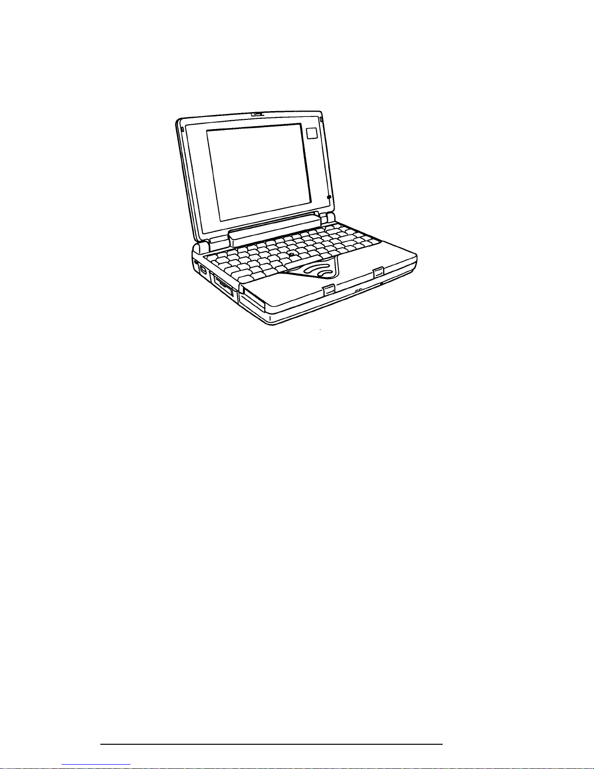
The T2100/T2105 Series Personal Computer is shown in Figure 1-1, and its system configuration is illustrated in Figure 1-2.
Figure 1-1 T2100/T2105 Series personal computer
T2100 Series
1-5
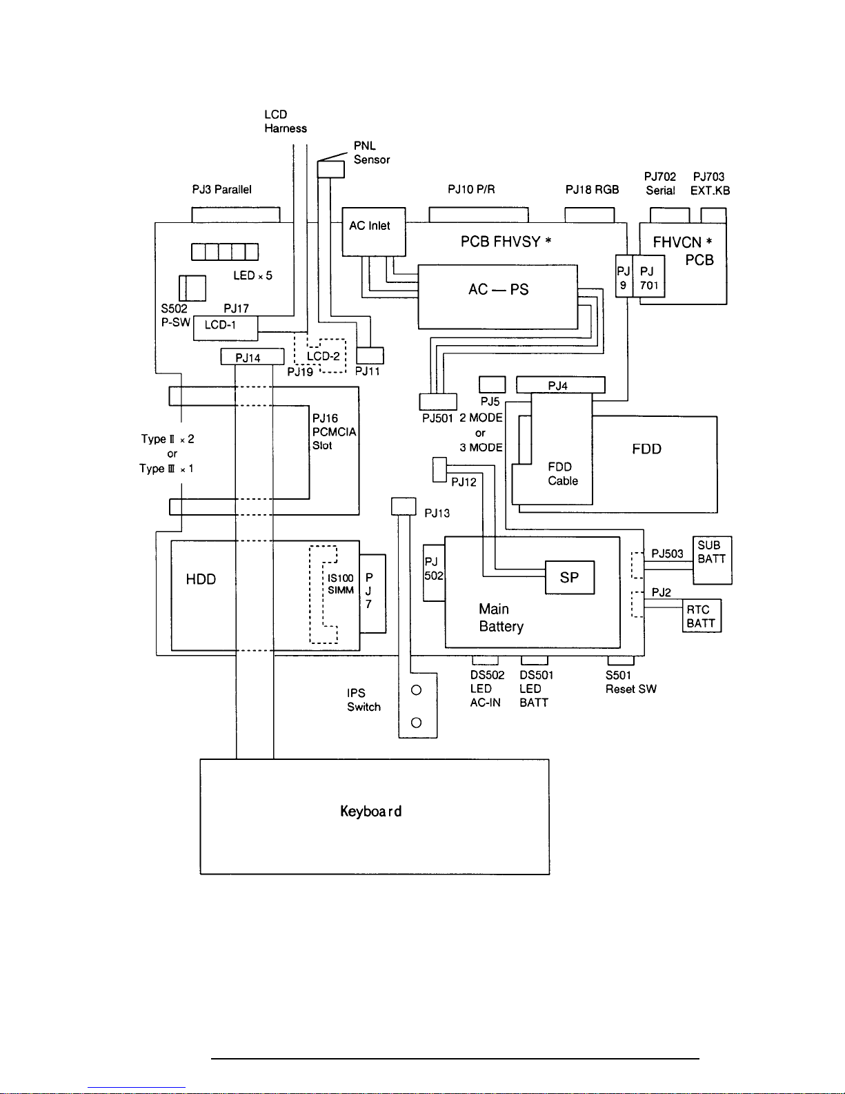
Figure 1-2 T2100/T2105 Series system unit configuration
T2100 Series
1-6
1.2 System Unit Block Diagram
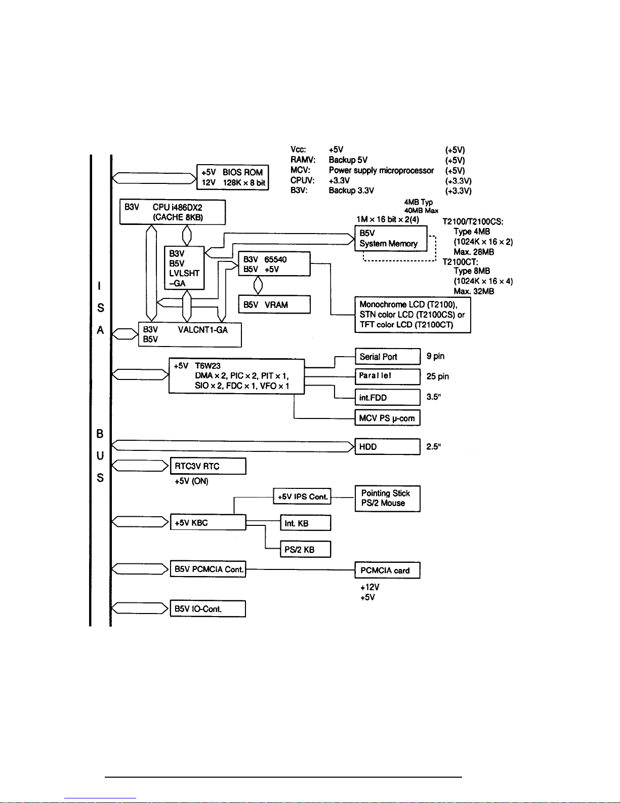
Figure 1-3 is a block diagram of the T2100/T2105 Series system unit.
Figure 1-3 T2100/T2105 Series system board block diagram
T2100 Series

1-7
The T2100/T2105 Series system board contains the following functional components:
❑ One SL Enhanced Intel 486DX2-50 32-bit math coprocessor.
i486DX2 operates at 50 MHz and 3.3 volts.
❑ Standard RAM
4 Mbytes, two 1024 x 16-bit chips (T2100/T2100CS)
8 Mbytes, four 1024 x 16-bit chips (T2100CT)
5 volt operation
No parity bit
Access time: 70 ns
Data transfer is 32-bit width.
❑ Cache memory
Eight (8) Kbytes of cache memory are stored inside the i486DX2.
Four-way set-associative method.
❑ BIOS ROM (Flash EEPROM)
128 Kbytes (one 128Kx8-bit chip) of memory.
64 Kbytes are used for the system BIOS.
40 Kbytes are used for the VGA BIOS.
24 Kbytes are reserved.
Access time: 150 ns.
Data transfer is 8-bit width.
❑ Video Ram
512 Kbytes (T2100).
1 Mbyte (T2100CS/T2100CT).
5 volt operation.
Access time: 70 ns.
❑ Optional memory
One expansion memory slot is available for 4, 8, 16 and 24 Mbyte memory
modules.
Total maximum memory size is 28 Mbytes for the T2100/T2100CS and 32
Mbytes for the T2100CT (if a 24 Mbyte module card is installed.)
3.3 volt operation
No parity bit
Access time: 70 ns
T2100 Series

1-8
❑ A Super Integration (SI) Gate Array incorporates the following components:
- Two DMACs 8237
- Two PICs 8259 equivalent
- Two SIOs 16450 equivalent (One SIO is not used.)
- One PIT 8254 equivalent
- One FDC TC8565 equivalent
- One VFO TC8568 equivalent
- One I/O port decode
- One SIO port control
- One printer port control
- One FDD control
- One speaker control
- One power communication control
❑ System Controller Gate Array (SYSCNT-GA)
This gate array has the following functions:
Memory control
DRAM control
CPU control
Bus control
Compatible bus interface control
Compatible bus access control
DMAC control
I/O control
Address latch control
Address transfer
Address latch
DMA address generation
Refresh address generation
I/O register control
Compatible I/O port
Register storing at resume mode power off
Special register
Processing speed control
Data bus transfer (32-bit to 16-bit) control
Data latch
❑ PCMCIA Controller Gate Array
PCMCIA (ToPIC) control
❑ Video Controller Gate Array
The T2100/T2105 Series internal display controller (C&T65540) (3.3/5 volts
operation) controls the internal VGA display and external SVGA compatible
display.
T2100 Series

1-9
❑ Keyboard Controller (KBC)
One M38802 chip is used.
The KBC, which includes the keyboard scan controller and keyboard interface
controller, controls the internal keyboard, external keyboard port, and PS/2
mouse port.
❑ Real Time Clock (RTC)
A T9934 chip with 128 bytes of memory is used. Fourteen bytes of memory
are used for the calendar and clock, and the remaining 114 bytes are used for
system configuration data.
❑ IO-CNT GA
This gate array has the following functions:
System interface
Hot key control (KBC interface)
PS interface
BIOS ROM interface
NEXUS GA function
❑ AccuPoint Controller (U43SC11X)
This controller emulates the AccuPoint signals to the PS/2 mouse on the port
replicator signal, and sends them to the KBC.
T2100 Series
1-10
1.3 3.5-inch Floppy Disk Drive
The T2100/T2105 Series 3.5-inch Floppy Disk Drive (FDD) is a thin, high-performance
reliable drive that supports 720 KB (formatted) 2DD and 1.44 MB (formatted) 2HD 3.5-inch
floppy disks.
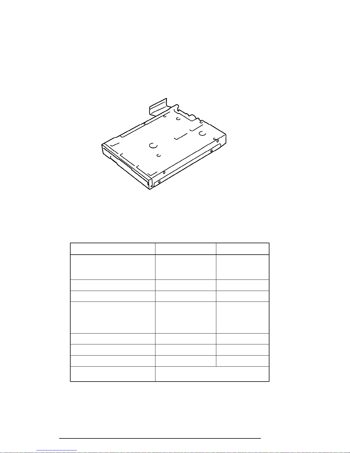
The FDD is shown in Figure 1-4, and its specifications are listed in Table 1-1.
Figure 1-4 3.5-inch FDD
Table 1-1 3.5-inch FDD specifications
Item 2 MB mode 1 MB mode
Storage capacity (KB)
Unformatted 2,000 1,000
Formatted 1,311 737
Number of heads 2 2
Number of cylinders 80 80
Access time (ms)
Track to track 3 3
Average 181 181
Head settling time 15 15
Recording track density (tpi) 135 135
Data transfer rate (Kbps) 500 250
Rotation speed (rpm) 300 300
Recording method Modified Frequency Modulation (MFM)
T2100 Series
1-11
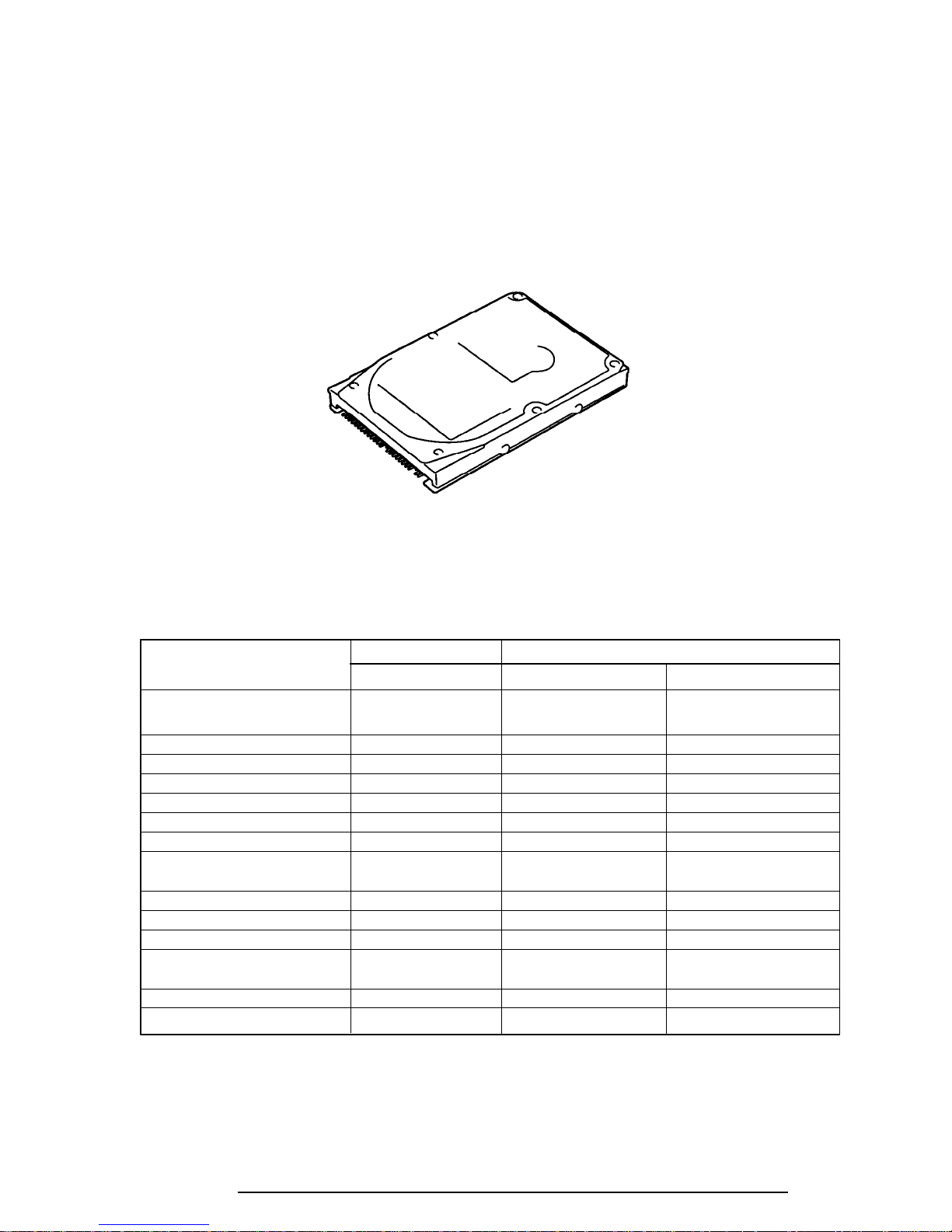
1.4 2.5-inch Hard Disk Drive
The Hard Disk Drive (HDD) is a random access, nonvolatile storage device. It has a nonremovable 2.5-inch magnetic disk and mini-winchester type magnetic heads.
The T2100 supports a 260 MB HDD. The T2100CS and T2100CT support a 350MB HDD.
An HDD is shown in Figure 1-5, and specifications for the HDDs are listed in Table 1-2.
Figure 1-5 2.5-inch HDD
Table 1-2 2.5-inch HDD specifications
Item
Storage capacity (MB)
Formatted 262 352 350
Number of disks 2 2 2
Data heads 4 4 4
Data surfaces 4 4 4
Tracks per surface 1,920 2,050 905
Sectors per track 49 to 83 60 to 106 53 to 95
Bytes per sector (bps) 512 512 512
Access time (ms)
Track to track 3 3 3
Average 13 13 12
Maximum stroke 25 25 20
Rotation speed (rpm) 4,000 4,200 3,750
Data transfer rate (bps)
To/from media 18.9 to 31.6 M 25.0 to 43.75 M 19.0 to 32.0 M
Interleave 1:1 1:1 1:1
Recording method 1-7 RLL 1-7 RLL 1-7 RLL
260 MB 350 MB
MK1724FCV MK1824FCV CFL350A
T2100 Series
1-12
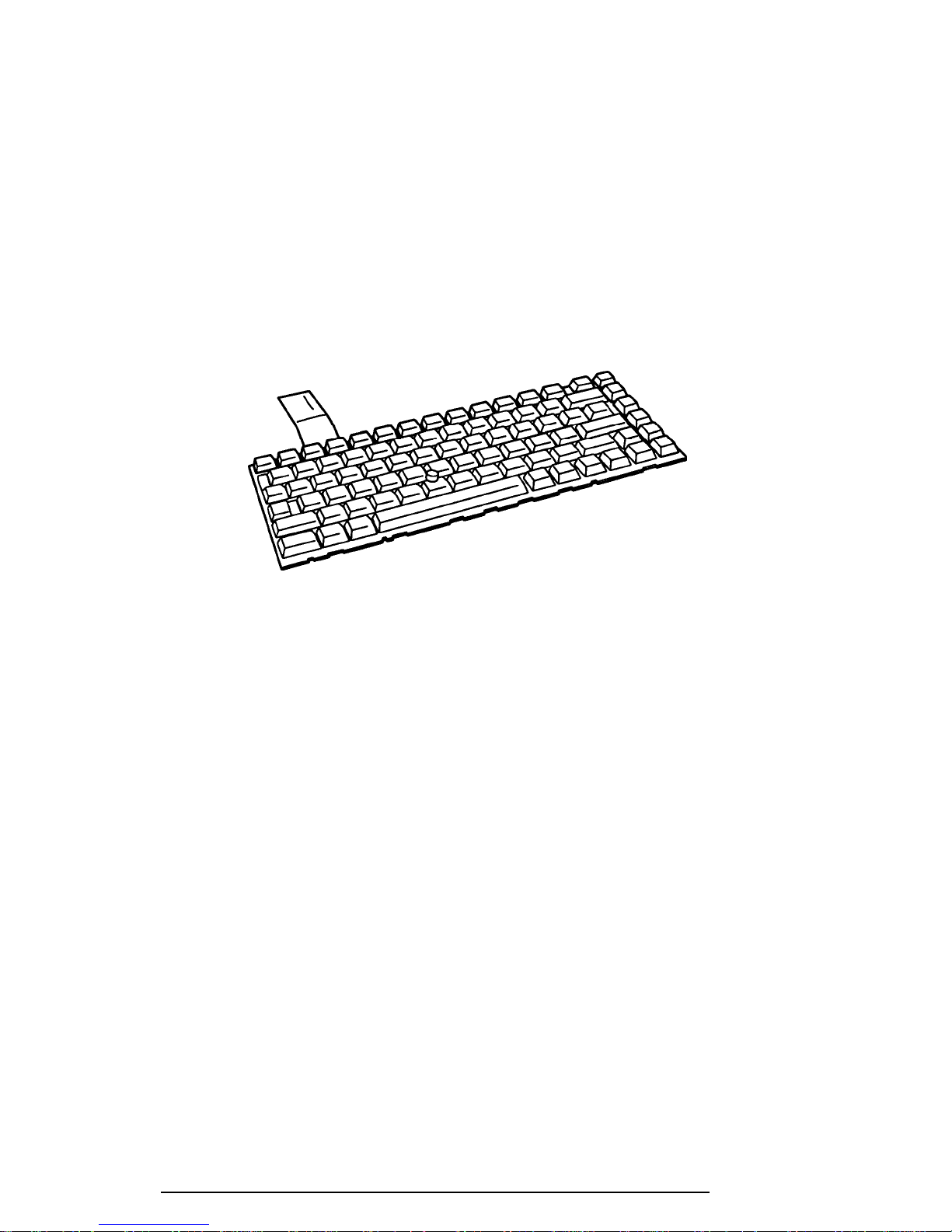
1.5 Keyboard
The 82-(USA) or 84-(European) key keyboard is mounted on the T2100/T2105 Series’s
system unit, and is connected to the keyboard controller on the system board through a 25-pin
flat cable.
The T2100/T2105 Series pointer control stick, located in the center of the keyboard, provides
convenient control of the cursor without requiring desk space for a mouse. The keyboard is
shown in Figure 1-6.
See Appendix F for optional keyboard configurations.
Figure 1-6 Keyboard
T2100 Series
1-13
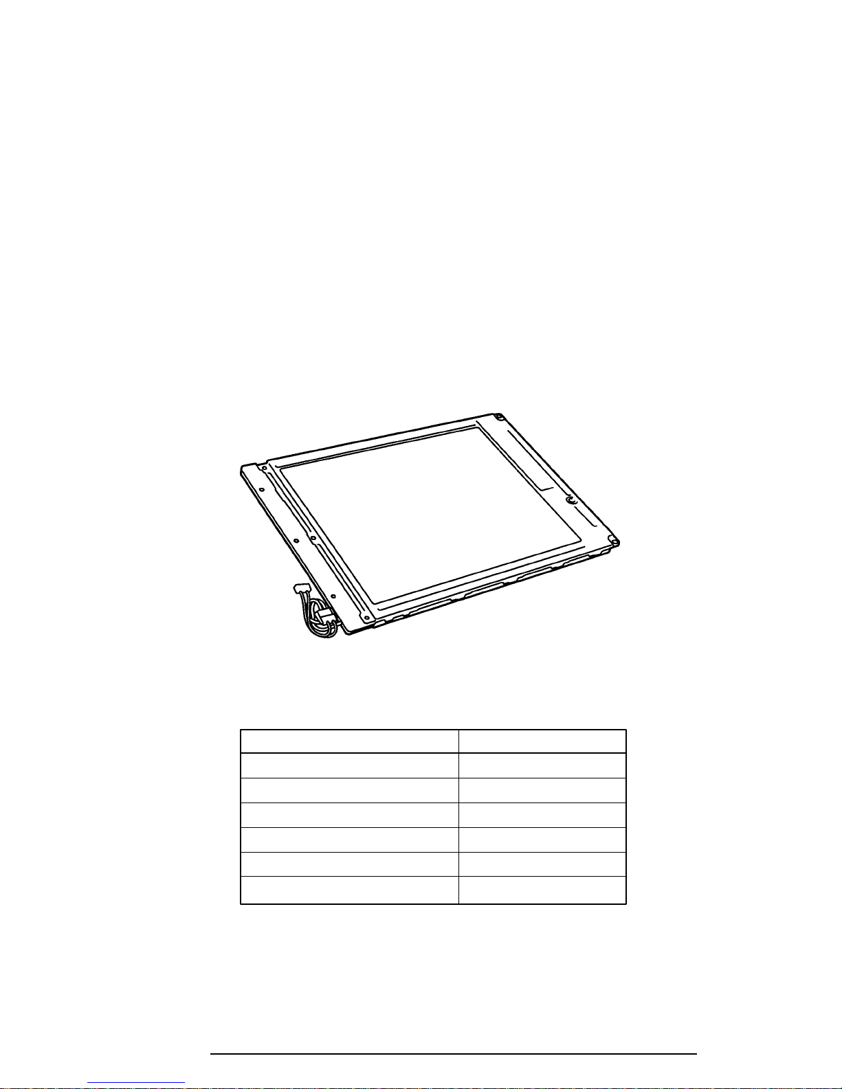
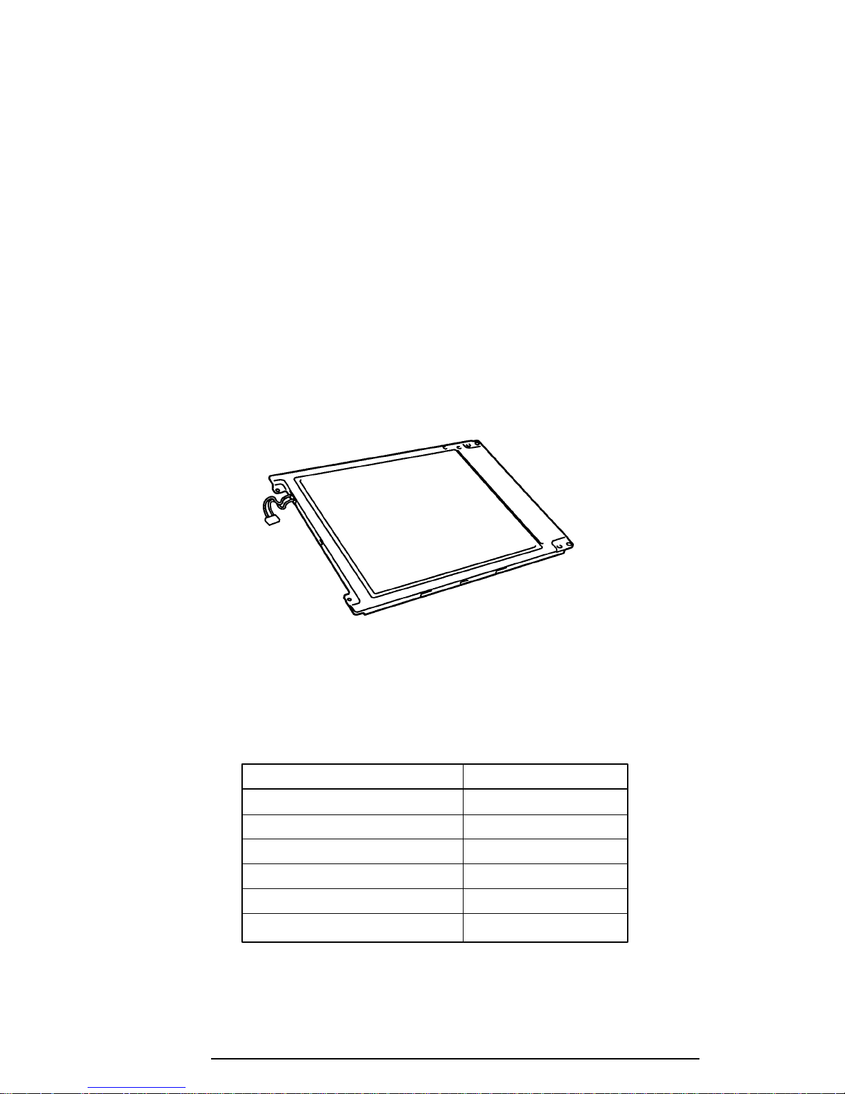
1.6 Monochrome LCD (T2100)
The monochrome Liquid Crystal Display (LCD) is composed of an LCD module, a Fluorescent Lamp (FL), and an FL inverter board.
1.6.1 Monochrome LCD Module
The T2100 monochrome LCD supports 640x480 pixels with a Video controller and 64 levels
of gray. The video controller includes the functions of the Video Graphics Array (VGA).
The LCD receives vertical and horizontal synchronizing signals, 8-bit data signals (4-bit upper
block data signals and 4-bit lower block data signals), and shift clock for data transmission.
All signals are CMOS-level compatible.
The sidelit LCD is shown in Figure 1-7, and its specifications are listed in Table 1-3.
Number of dots (dots) 640 x 480
Dot pitch (mm) 0.30 (W) x 0.30 (H)
Display area (mm) 196 (W) x 147.6 (H)
Contrast 17:1 (minimum)
FL current (mA) 4.6
FL frequency (KHz) 40
T2100 Series
Figure 1-7 Monochrome LCD
Table 1-3 Monochrome LCD specifications
Item Specifications

1-14
1.6.2 Monochrome Fluorescent Lamp (FL) Inverter Board
The FL inverter board supplies high frequency current needed to illuminate the FL.
Specifications for the FL inverter board are listed in Table 1-4.
Table 1-4 Monochrome FL inverter board specifications
Item Specifications
Input Voltage (VDC) 5
Power (W) 4.25
Output Voltage (VAC) 1,100
Current (mA) 4.6
Frequency (KHz) 40
T2100 Series
1-15
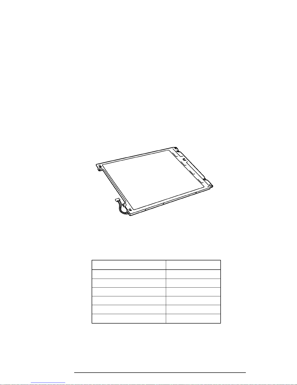
1.7 STN Color LCD (T2100CS)
The STN Color Liquid Crystal Display (LCD) contains an LCD module, a Fluorescent Lamp
(FL), and an FL inverter board.
1.7.1 STN Color LCD Module
The T2100CS STN color LCD is backlit and supports 640x480 pixels with a Video controller. This controller includes the functions of the Video Graphics Array (VGA).
The T2100CS’s LCD receives vertical and horizontal synchronizing signals, 16-bit data signal,
8-bit upper block data signal, 8-bit lower block data signal, and shift clock for data transmission. All signals are CMOS-level compatible.
The STN LCD is shown in Figure 1-8, and its specifications are listed in Table 1-5.
Figure 1-8 STN color LCD
Table 1-5 STN color LCD specifications
Item Specifications
Number of Dots (dots) 640 x 480
Dot pitch (mm) 0.33 x 0.33
Display area (mm) 217.2 (W) x 164.4 (H)
Contrast (Typically) 20:1
FL current (mA) 5.0
FL frequency (KHz) 40
T2100 Series

1-16
1.7.2 STN Color Fluorescent Lamp (FL) Inverter Board
The FL inverter board supplies high frequency current to light the LCD’s Fluorescent Lamp.
Specifications for the FL inverter are listed in Table 1-6.
Table 1-6 STN color FL inverter board specifications
Item Specifications
Input Voltage (VDC) 5
Power (W) 4.25
Output Voltage (VAC) 1,100
Current (mA) 5.0
Frequency (KHz) 40
T2100 Series
1-17
1.8 TFT Color LCD (T2100CT)
The TFT Color Liquid Crystal Display (LCD) contains an LCD module, a Fluorescent Lamp
(FL), and an FL inverter board.
1.8.1 TFT Color LCD Module
The T2100CT TFT color LCD supports 640x480 pixels with an internal display controller.
This controller includes the functions of Video Graphics Array (VGA) and Super VGA
(SVGA) for an external display.
The LCD receives 12-bit data signals, data enable signals, and shift clock for data transmission. All signals are CMOS-level compatible.
The TFT LCD is shown in Figure 1-9, and its specifications are listed in Table 1-7.
Number of dots (dots) 640 x 480
Dot pitch (mm) 0.267 (W) x 0.27 (H)
Display area (mm) 170.9 (W) x 129.6 (H)
Contrast 60:1 (minimum)
FL current (mA) 6.0
FL frequency (KHz) 40
T2100 Series
Figure 1-9 TFT color LCD
Table 1-7 TFT color LCD specifications
Item Specifications

1-18
1.8.2 TFT Color Fluorescent Lamp (FL) Inverter Board
The FL inverter board supplies high frequency current to light the LCD’s Fluorescent Lamp.
Specifications for the FL inverter are listed in Table 1-8.
Table 1-8 TFT FL inverter board specifications
Item Specifications
Input Voltage (VDC) 5
Power (W) 4.25
Output Voltage (VAC) 1,100 (r.m.s)
Current (mA) 6.0
Frequency (KHz) 40
T2100 Series

1-19
1.9 Power Supply
The power supply, which supplies five kinds of voltages to the T2100/T2105 Series system
board, has one microprocessor and operates at 500 KHz. The power supply performs the
following functions:
1. Determines if the AC cord or battery is connected to the computer.
2. Detects DC output and circuit malfunctions.
3. Controls the LED indicator and speaker.
4. Turns the battery charging system on and off and detects a fully charged battery.
5. Determines if the power can be turned on and off.
6. Provides more accurate detection of a low battery.
7. Calculates the remaining battery capacity.
The power supply output rating is specified in Table 1-9.
Table 1-9 Power supply output rating
DC Regulation Maximum
Use for Name voltage tolerance current Ripple
(V) (%) (mA) (mV)
System logic, FDD, HDD, VCC +5 ±5 1,400 100
Display
PCMCIA, Flash ROM P12V +12 ±5 100 240
CPU, GA B3V +3.3 ±5 1,100 60
VRAM, GA, RAM B5V +4.7 ±5 650 100
T2100 Series

1-20
1.10 Batteries
The T2100/T2105 Series has three types of batteries:
❑ Main battery pack
❑ Backup battery
❑ Real Time Clock (RTC) battery
Battery specifications are listed in Table 1-10.
Table 1-10 Battery specifications
Battery name Material Output voltage Capacity
Main battery Nickel Metal Hydride 12 V 2,600 mAh
Backup battery Nickel Metal Hydride 7.2 V 120 mAh
RTC battery Lithium-Vanadium 3.0 V 50 mAh
1.10.1 Main Battery
The removable main battery pack is the computer’s main power source when the AC power
cord is not attached. The main battery recharges the backup battery when the system's power
is on. The backup and main batteries maintain the state of the computer when you enable
AutoResume.
❑ Battery Indicator
The Battery indicator is located on the front of the T2100/T2105 Series. The indicator shows the status of the removable battery pack.
The status can be determined by color:
Orange The battery is being charged. (AC power cord is attached.)
Green The battery is fully charged. (AC power cord is attached.)
Blinking orange The battery is low when the power is on.
No light Under any other conditions, the LED does not light.
T2100 Series

1-21
1.10.2 Battery Charging Control
Battery charging is controlled by a microprocessor that is mounted on the power supply. The
microprocessor controls whether the charge is on or off and detects a full charge when the AC
power cord and main battery are attached to the computer.
The system charges the battery using quick charge when the system is powered off, or trickle
charge when the system is powered on. The trickle charge state maintains the full charge of
the battery. Table 1-11 lists the time required for charging the main battery.
Table 1-11 Time required for charges
Power Charging time
Power off About 2.5 hours
Power on Trickle charge
If one of the following occurs, the battery quick-charge process stops.
1. The battery becomes fully charged.
2. The battery is removed.
3. The battery or AC output voltage is abnormal.
4. The charge current is abnormal.
When the main battery is fully charged and the AC power cord is attached, the power supply
microprocessor automatically changes quick charge to trickle charge.
T2100 Series

1-22
1.10.3 Backup Battery
The backup battery maintains data for AutoResume. The power source used to back up the
AutoResume data is determined according to the following priority:
AC power > Main battery > Backup battery
The backup battery is charged by the main battery or AC power cord when the system is
powered on. Table 1-12 lists the charging time and data preservation period of the backup
battery.
Table 1-12 Backup battery charging/data preservation time
Backup Battery Time
Charging Time Power On 20 H
Power Off (with AC power) 20 H
Power Off (without AC power) Doesn't charge
Data preservation period (full charge) 5 H
1.10.4 RTC battery
The RTC battery provides power to keep the current date, time and other setup information in
memory while the computer is turned off. Table 1-13 shows the charging time and data
preservation period of the RTC battery.
Table 1-13 RTC battery charging/data preservation time
RTC Battery Time
Charging Time With AC power 48 H
or main battery
Data preservation period (full charge) 1 month
T2100 Series

2-1
2.1 Troubleshooting
Chapter 2 describes how to determine if a Field Replaceable Unit (FRU) in the T2100/T2105
Series is causing the computer to malfunction. The FRUs covered include the:
1. System Board
2. Floppy Disk Drive
3. Hard Disk Drive
4. Keyboard
5. Display
Diagnostics Disk operations are described in Chapter 3 and detailed replacement procedures
are given in Chapter 4.
The following tools are necessary for implementing the troubleshooting procedures:
1. A T2100/T2105 Series Diagnostics Disk
2. A Phillips screwdriver (2 mm)
3. A Toshiba MS-DOS system disk(s)
4. A 2DD or 2HD formatted work disk for floppy disk drive testing
5. A cleaning kit for floppy disk drive troubleshooting
6. A printer port LED
7. An RS-232-C wraparound connector
8. A printer wraparound connector
9. A multimeter
10. An external CRT
T2100 Series

2-2
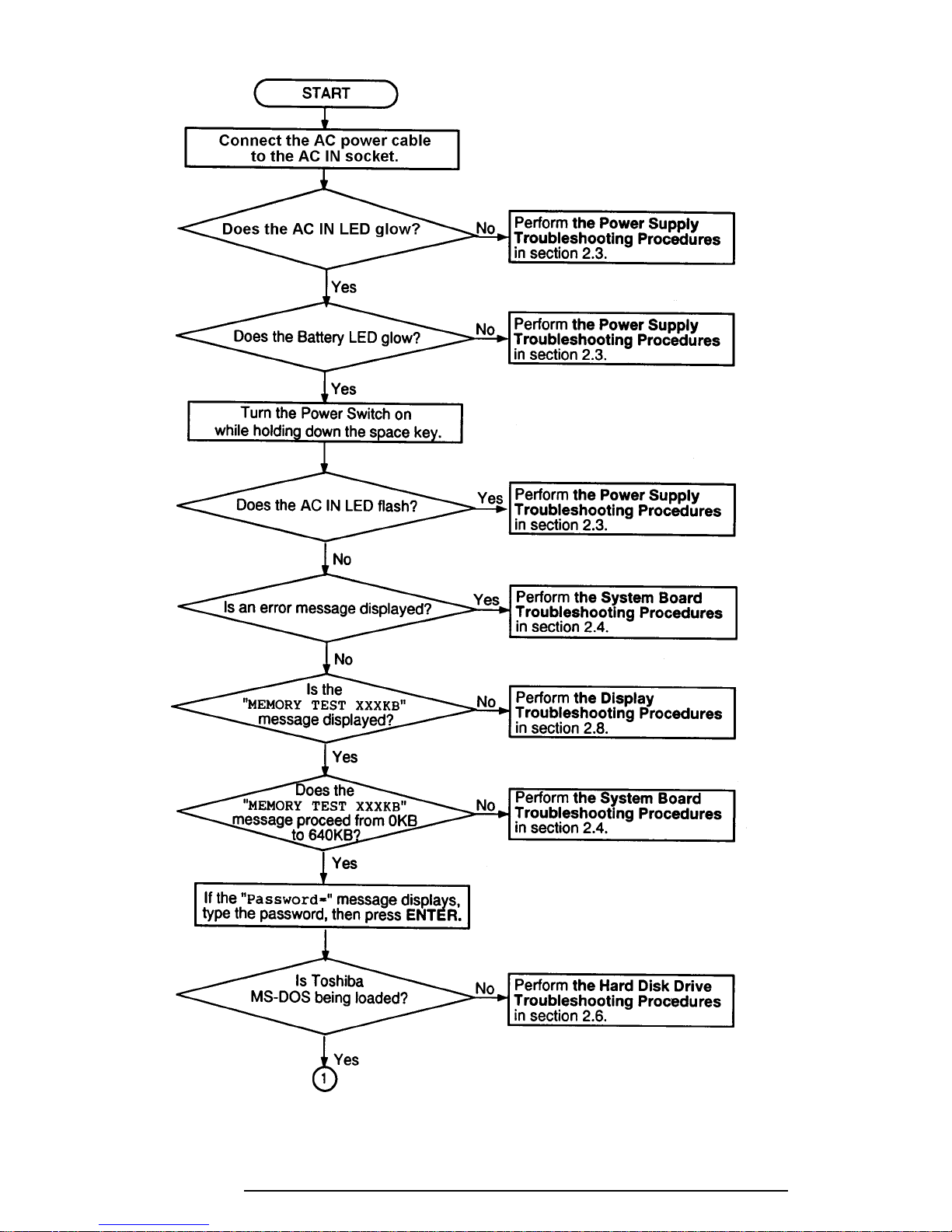
2.2 Troubleshooting Flowchart
Use the flowchart in figure 2-1 as a guide for determining which troubleshooting procedures
to execute. However, before going through the flowchart steps, verify the following:
❑ Ask the user if a password is registered, and if it is, ask him or her to enter the pass-
word. If the user has forgotten the password, connect the printer port wraparound
board (F31PRT), then turn the POWER switch on. The computer will override the
password function by erasing the current password.
❑ Verify with the customer that Toshiba MS-DOS is installed on the hard disk. Non-
Toshiba operating systems can cause the computer to malfunction.
❑ Make sure all optional equipment is disconnected from the computer.
❑ Make sure the floppy disk drive is empty.
T2100 Series
T2100 Series
2-3
Figure 2-1 Troubleshooting flowchart (1/2)
2-4
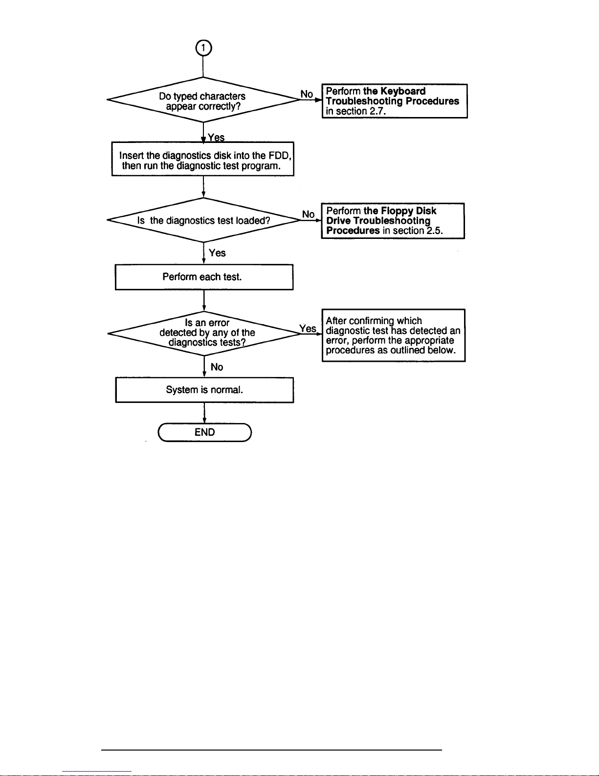
Figure 2-1 Troubleshooting flowchart (2/2)
If the diagnostics program cannot detect an error, the problem may be intermittent. The
Running Test program should be executed several times to isolate the problem. Check the
Log Utilities function to confirm which diagnostic test detected an error(s), then perform the
appropriate troubleshooting procedures as follows:
1. If an error is detected on the system test, memory test, display test, ASYNC test,
printer test, or real timer test, perform the system board troubleshooting procedures in Section 2.4.
2. If an error is detected on the keyboard test, perform the keyboard troubleshooting
procedures in Section 2.7.
3. If an error is detected on the floppy disk test, perform the floppy disk drive
troubleshooting procedures in Section 2.5.
4. If an error is detected on the hard disk test, perform the hard disk drive
troubleshooting procedures in Section 2.6.
T2100 Series

2-5
2.3 Power Supply Troubleshooting
The T2100/T2105 Series' power supply controls many functions and components in the
computer. To determine if the power supply is functioning properly, start with Procedure 1
and continue with the other Procedures as instructed. The procedures described in this
section are:
Procedure 1: AC IN LED Indicator Check
Procedure 2: Battery LED Indicator Check
Procedure 3: AC Power Supply (PS) Unit Replacement Check
T2100 Series

2-6
Procedure 1 AC IN LED Indicator Check
The T2100 Series computer’s AC Power Supply (PS) unit converts AC power to DC power
and contains a charging circuit which charges the computer’s batteries. The AC power cord
connects to the AC IN socket connector on the back of the computer. When the AC power
cord is connected and the power is turned off, the AC charges the batteries.
The AC IN indicator displays whether or not the AC power cord is connected and supplying
power.
❑ When the AC IN indicator is green, the AC power cord is connected and supplying
power to the T2100/T2105 Series computer.
❑ If the AC IN indicator does not light, the AC power cord is not supplying power to
the computer or the AC power cord is not attached to the computer, go to Check 1.
❑ If the AC IN indicator is flashing orange, the AC power cord’s voltage supply is
abnormal or the power supply is not functioning properly, go to Check 1.
If any of the above indicator conditions are abnormal, make sure the LED indicator lights are
not burned out before performing the following Checks as indicated.
Check 1 Make sure the correct AC power cord is firmly plugged into the AC IN socket on
the back of the computer.
Check 2 If the AC IN indicator flashes orange when the AC power cord is connected,
output voltage is abnormal. Connect a new AC power cord and turn the computer
on again to verify the indicator condition.
Check 3 The battery pack may be malfunctioning. Replace the battery pack with a new one
and turn the computer on again. If the problem still exists, perform Check 4.
Check 4 Place the computer in an environment between –20°C and 70°C until the computer
is at the ambient temperature. Repeat the steps which caused the computer to
operate abnormally. If the same problem still appears, perform Procedure 2.
T2100 Series

2-7
Procedure 2 Battery LED Indicator Check
The Battery LED indicator shows the battery charging status. The Battery LED, identified by
a battery indicator on the front of the computer, glows orange when the AC power cord is
charging the T2100/T2105 Series’s battery pack.
❑ If the Battery LED indicator glows green, the AC power cord is connected and the
battery is fully charged.
❑ If the Battery LED indicator glows orange, the AC power cord is connected and the
battery is being charged.
❑ If the Battery LED indicator does not glow, go to Check 1.
Check 1 Make sure the AC power cord is firmly plugged into the AC IN socket and wall
outlet. If these cables are connected correctly, go to Check 2.
Check 2 Make sure the battery pack is installed in the computer correctly. If the battery
pack is installed correctly, go to Check 3.
Check 3 Remove the battery pack and check that the battery terminal is clean and not bent.
■ If the terminal appears dirty, clean it gently with a cotton swab dipped in
alcohol.
■ If the terminal looks bent or damaged, replace the system board.
■ If the battery terminal is clean and not bent, go to Check 4.
Check 4 Connect a new AC power cord. If the Battery LED indicator still does not glow,
go to Check 5.
Check 5 Install a new battery pack. If the Battery LED indicator still does not glow, go to
Procedure 3.
T2100 Series

2-8
Procedure 3 AC Power Supply (PS) Unit Replacement Check
The PCB incorporates the system board and the AC PS unit. Power is supplied to the power
supply board through the AC IN plug located on the internal AC adapter. If either the power
supply board or the system board is damaged, replace the AC PS unit.
Refer to Chapter 4 for instructions on how to disassemble the T2100/T2105 Series computer,
and then perform the following check.
Check 1 Replace the AC PS unit with a new one and restart the system. If the problem still
exists, other FRUs may be damaged.
T2100 Series
 Loading...