


Part 1
Hardware Overview
1-1

This page intentionally left blank
1-2

Contents
1.1 General ....................................................................................................................... 1-5
1.2 System Unit ................................................................................................................ 1-7
1.3 3.5-inch Floppy Disk Drive....................................................................................... 1-10
1.4 2.5-inch Hard Disk Drive .......................................................................................... 1-11
1.5 Keyboard .................................................................................................................. 1-12
1.6 Sidelit Liquid Crystal Display ................................................................................... 1-13
Tables
Table 1-1 T2000SXe 3.5-inch FDD specifications......................................................... 1-10
Table 1-2 T2000SXe 2.5-inch HDD specifications ........................................................ 1-11
Table 1-3 Sidelit LCD specifications ............................................................................. 1-13
Table 1-4 FL inverter specifications .............................................................................. 1-14
Figures
Figure 1-1 T2000SXe personal computer.......................................................................... 1-6
Figure 1-2 T2000SXe system unit configuration .............................................................. 1-6
Figure 1-3 T2000SXe block diagram ................................................................................ 1-7
Figure 1-4 T2000SXe 3.5-inch FDD ............................................................................... 1-10
Figure 1-5 T2000SXe 2.5-inch HDD............................................................................... 1-11
Figure 1-6 T2000SXe keyboard ...................................................................................... 1-12
Figure 1-7 Sidelit LCD ................................................................................................... 1-13
1-3

This page intentionally left blank
1-4

1.1 General
The Toshiba T2000SXe is one of the lightest and most advanced portable computers available
offering high technology, high speed, excellent legibility, IBM PC/AT compatibility, and battery
operation.
The T2000SXe is one of a new class of portables called notebook computers, the lightest portable
computers available.
The T2000SXe system unit has the following features:
❑ The Central Processing Unit (CPU) is an 80386SX-20 32-bit microprocessor, operating at
20MHz.
❑ The standard Random Access Memory (RAM) capacity is 2MB. With 2MB, 4MB, or 8MB
expansion memory cards, the T2000SXe system can have a maximum of 10MB of RAM.
❑ An 80387SX-20 Numeric Data Processor (NDP) can be installed.
❑ The Liquid Crystal Display (LCD) supports 640x480 pixels with Video Graphics Array
(VGA) compatibility and 16 levels of gray.
❑ The display controller supports VGA functions through the High Resolution Graphics
Subsystem (HRGS).
❑ The 3.5-inch Floppy Disk Drive (FDD) supports two memory formats:
• 1.44MB double-sided, high-density, double-track (2HD)
• 720KB double-sided, double-density, double-track (2DD)
❑ The 2.5-inch Hard Disk Drive (HDD) has either a 40MB or 60MB capacity.
❑ The keyboard is an 86/88-key keyboard that is fully compatible with the IBM standard 101/
102-key keyboard.
❑ The universal auto-sensing AC adapter can be used in a range from 100 to 240 volts AC.
❑ A built-in modem slot is available for an optional built-in modem.
❑ A parallel port, serial port, RGB port, numeric keypad port, and expansion bus connector
are provided to allow the T2000SXe to interface with a variety of optional equipment.
❑ The T2000SXe supports the Toshiba AutoResume feature, storing the data and configura-
tion information when the power is turned off.
❑ The Real Time Clock (RTC) continuously stores the date and time even when the power is
turned off.
1-5

The T2000SXe Personal Computer is shown in Figure 1-1 and the T2000SXe system configuration
is shown in Figure 1-2.
Figure 1-1 T2000SXe personal computer
Figure 1-2 T2000SXe system unit configuration
1-6

1.2 System Unit
Figure 1-3 shows the block diagram of the T2000SXe’s system unit.
Figure 1-3 T2000SXe block diagram
1-7

The system board in the T2000SXe is composed of the following major components:
❑ Central Processing Unit (CPU): 80386SX-20
The CPU is a 32-bit microprocessor operating at 20MHz (fast mode) and 10MHz (slow
mode) clock speeds.
❑ Numeric Data Processor (NDP) socket for the 80387SX-20 (optional)
❑ Super Integration (SI): T9778A
The SI stores the following components:
· Two Direct Memory Access Controllers (DMACs): 82C37A
· Two Programmable Interrupt Controllers (PICs): 82C59A
· One Programmable Interval Timer (PIT): 82C54
· One Floppy Disk Controller (FDC): TC8565
· One Serial Input/Output Controller (SIO): TC8570
❑ Variable Frequency Oscillator (VFO): TC8568AM
The VFO chip is used for Floppy Disk Drive control logic.
❑ Real Time Clock (RTC): 146818AF
The RTC chip stores the date, time, and system configuration with power supplied from the
RTC battery.
❑ Keyboard Interface Controller (KBIC): 80C42
❑ Keyboard Scan Controller (KBSC): 80C50
❑ Power Supply Controller (PSC): U47C440
❑ Memory:
Standard RAM: 2MB
Backup RAM: 32KB
BIOS ROM: 128KB (96KB are used)
BIOS ROM also contains the Initial Reliability Test (IRT), the system’s Basic Input/
Output System (BIOS), and the video BIOS.
Video RAM: 256KB
Optional memory cards:
The system can have up to 10MB of RAM by installing an optional memory card.
❑ Gate arrays:
System control gate array: GA-SCNT2 (208-pin)
I/O control gate array: GA-IO CNT (176-pin)
VGA display controller: PVGA1F (132-pin)
1-8

❑ Oscillators (OSC):
14.7456MHz OSC (X1) is used for the SIO.
14.31818MHz OSC (X2) is used for the KBC.
44.9MHz OSC (X3), 28.322MHz OSC (X5), and 25.175MHz OSC (X6) are used for the
video.
40.0MHz OSC (X4) is used for the CPU.
24MHz OSC (X7) is used for the VFO.
32.768KHz OSC (X8) is used for the RTC.
500KHz OSC (X701) is used for the PSC.
See Appendix A for the location of the OSCs.
1-9
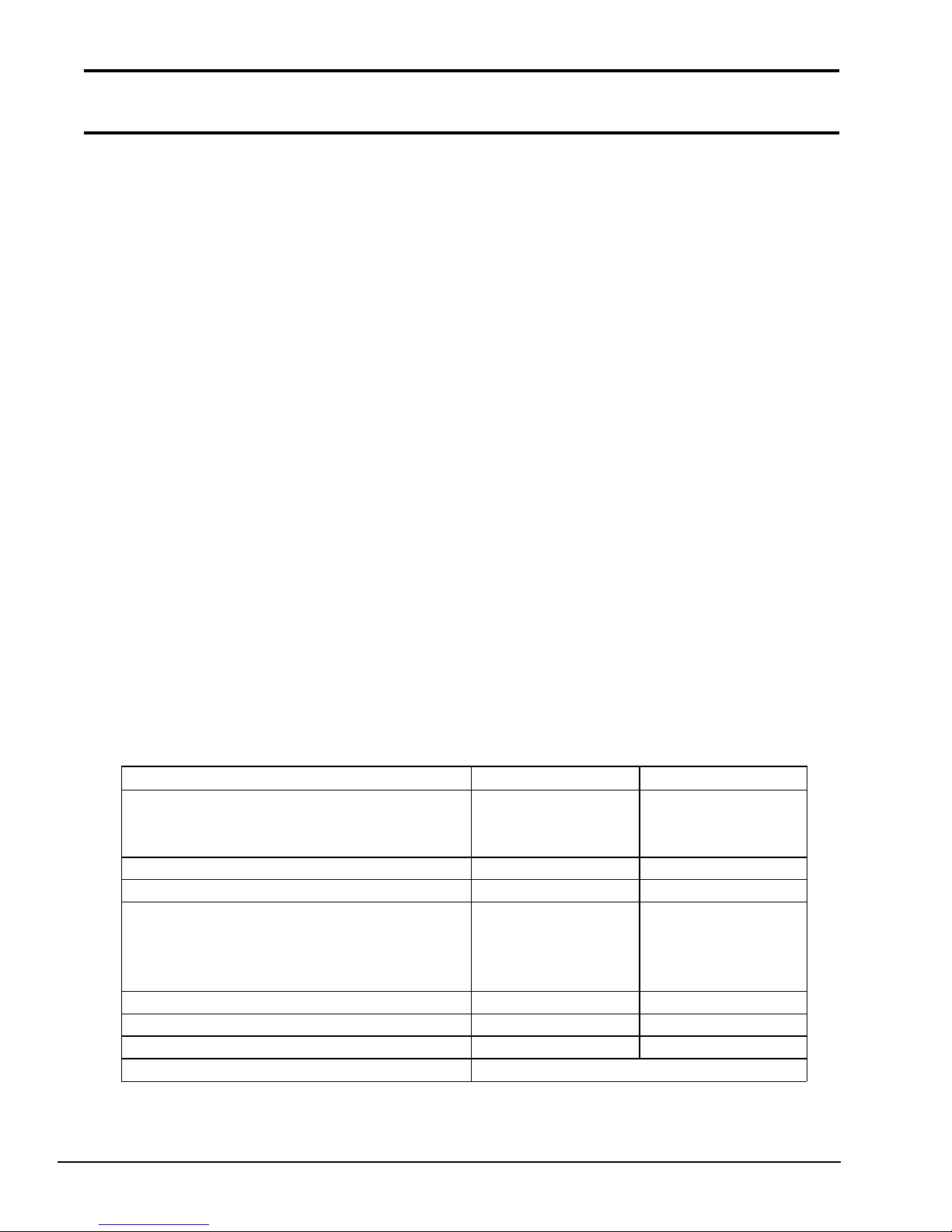
1.3 3.5-inch Floppy Disk Drive
Recording method M FM (modified frequency modulation)
The T2000SXe 3.5-inch Floppy Disk Drive (FDD) supports 720KB (formatted) 2DD and 1.44MB
(formatted) 2HD 3.5-inch floppy disks.
The T2000SXe FDD is shown in Figure 1-4 and its specifications are described in Table 1-1.
Figure 1-4 T2000SXe 3.5-inch FDD
Table 1-1 T2000SXe 3.5-inch FDD specifications
Ite m 2-Mbyte mode 1-Mbyte mode
Storage capacity (Kbyte)
Unformatted
Formatte d
Number of heads 2 2
Number of cylinders 80 80
Access time (ms)
Track to trac k
Average
Head settling time
Recording trac k density (tpi) 135 135
Data transfer rate (Kbps) 500 250
Rotation speed (rpm) 300 300
2,000
1,440
3
94
15
1,000
720
3
94
15
1-10
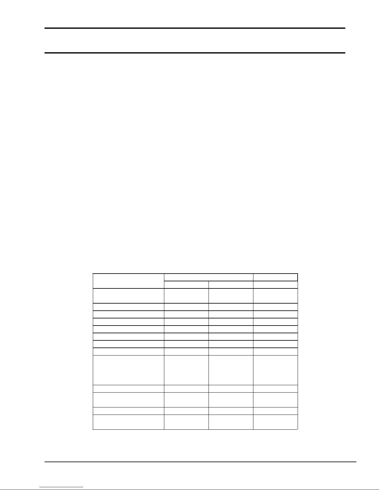
1.4 2.5-inch Hard Disk Drive
1-7 RLL
1-7 RLL
The 40MB or 60MB (formatted) Hard Disk Drive (HDD) is a random access storage device. It is
equipped with a non-removal 2.5-inch magnetic disk and mini-Winchester type magnetic heads.
The T2000SXe HDD is shown in Figure 1-5. The HDD specifications are described in Table 1-2.
Figure 1-5 T2000SXe 2.5-inch HDD
Table 1-2 T2000SXe 2.5-inch HDD specifications
It em
Sto rage capacity
Form atted (Mbytes)
Num ber of disks 2 2 2
Data heads 4 3 4
Data su rfaces 4 3 4
Tr acks per surface 55 2 791 (+2) 8 23
Tr acks per drive 2,208 2,373 (+6) 1,306
Sector s per track 38( +1) 35(+1) 38(+1)
Bytes per sector 51 2 51 2 51 2
Access time (ms)
T rack to track
Average
M aximum
Rotation speed (rpm) 3,486 3,109 3,444
Data transfer rate
To/from m edia (bps)
Interleav e 1:1 1:1 1:1
Recor ding m ethod 2-7 RLL/
CP- 2044 JD-E 2850P CP-2064
40- Mbyte 60- Mbyte
42.6 42.52 64.0
5
19
40
12 M 10 M 12 M
9
25
47
2-7 RLL 2-7 RLL/
5
19
40
1-11

1.5 Keyboard
The 86-key (USA) or 88-key (European) keyboard is mounted on the system unit. The keyboard is
connected to the keyboard controller on the system board through 8-pin and 12-pin flat cables. The
keyboard is shown in Figure 1-6.
See Appendix E for optional keyboard configurations.
1-12
Figure 1-6 T2000SXe keyboard

1.6 Sidelit Liquid Crystal Display
FL frequency (KHz) 35-43
The sidelit Liquid Crystal Display (LCD) is composed of an LCD module, a Fluorescent Lamp
(FL), and FL inverter board.
(1) LCD module
The T2000SXe sidelit LCD is illuminated from the side and supports 640x480 pixels with a High
Resolution Graphics Subsystem (HRGS) and 16 levels of gray. The HRGS includes the functions
of the Video Graphics Array (VGA).
The LCD receives vertical and horizontal synchronizing signals, 8-bit data signals (4-bit upper data
signal, 4-bit lower data signal), and shift clock for data transmission. All signals are CMOS-level
compatible.
The sidelit LCD is shown in Figure 1-7 and its specifications are described in Table 1-3.
Table 1-3 Sidelit LCD specifications
Item Specifications
Numbe r of dots (dots) 640x480
Dot dimens ion (mm) 0.24(W)x0.24(H)
Dot pitch (mm) 0.27(W)x0.27(H)
Display area (mm) 183.0(W)x136.0(H)
Contrast 15:1 (typ.)
FL c urrent (mA) 4.0-6.0
Figure 1-7 Sidelit LCD
1-13
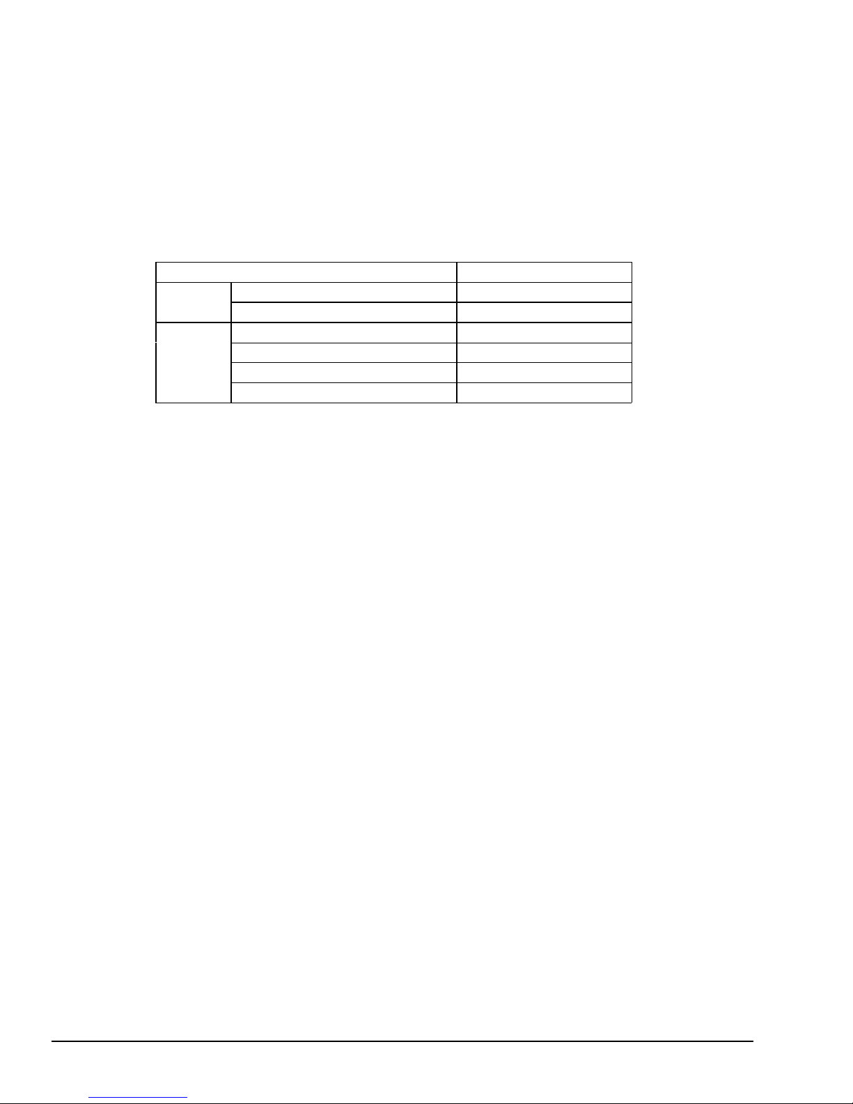
(2) Fluorescent Lamp inverter board
Bounds of curre nt (mA) 3.25-5.5
The FL inverter board supplies the high frequency current needed to illuminate the FL.
The specifications for the FL inverter are described in Table 1-4.
Table 1-4 FL inverter specifications
Ite m Specifications
Input Voltage (V) 12-24
Power (W) 3.6 (Max.)
Voltage (V) 800 (min.)
Output
Current (mA) 5.5
Frequenc y (KHz) 39
1-14

Part 2
Problem Isolation Procedures
2-1

This page intentionally left blank
2-2

Contents
2.1 General ....................................................................................................................... 2-5
2.2 Problem Isolation Flowchart....................................................................................... 2-6
2.3 Power Supply Problem Isolation Procedures............................................................... 2-8
2.4 System Board Problem Isolation Procedures ............................................................ 2-14
2.5 Floppy Disk Drive Problem Isolation Procedures ..................................................... 2-20
2.6 Hard Disk Drive Problem Isolation Procedures......................................................... 2-25
2.7 Keyboard Problem Isolation Procedures ................................................................... 2-30
2.8 Display Problem Isolation Procedures ...................................................................... 2-33
Tables
Table 2-1 Power supply error status .............................................................................. 2-10
Table 2-2 Normal status and error status of the printer port LED .................................. 2-17
Table 2-3 FDD error code and status ............................................................................. 2-23
Table 2-4 HDD error code and status............................................................................. 2-28
Figures
Figure 2-1 Problem isolation flowchart ............................................................................ 2-6
2-3

This page intentionally left blank
2-4

2.1 General
This part describes how to determine which Field Replaceable Unit (FRU) is causing the
T2000SXe to operate abnormally.
The FRUs covered are:
❑ Power supply unit
❑ System board (PCB FT3SYx)
❑ FDD
❑ HDD
❑ Keyboard
❑ Display
The Diagnostics Disk operations are described in Part 3 and detailed replacement procedures are
given in Part 4.
The following items are necessary for implementing the problem isolation procedures.
❑ T2000SXe Diagnostics Disk
❑ Phillips head screwdrivers (2mm, 3mm)
❑ Toshiba MS-DOS system disk
❑ 2DD or 2HD formatted work disk (for FDD testing)
❑ Cleaning disk kit (for FDD testing)
❑ Printer port LED
❑ RS-232-C wraparound connector
❑ Printer wraparound connector
❑ Multimeter
2-5
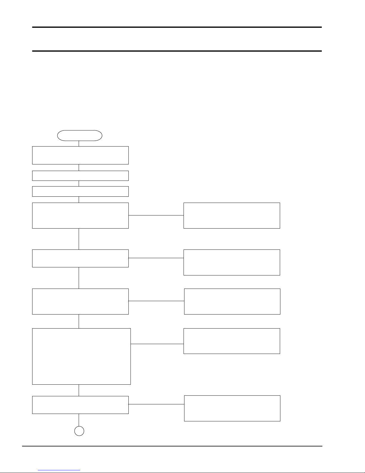
2.2 Problem Isolation Flowchart
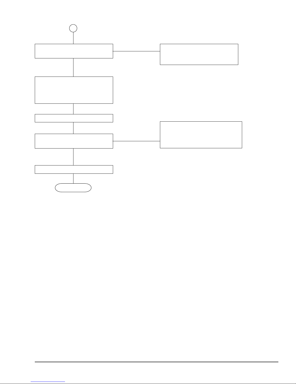
The flowchart in Figure 2-1 is used as a guide for determining which FRU is causing the T2000SXe
to operate abnormally. Before performing the procedures described in the flowchart, please confirm the following:
❑ Disconnect all optional equipment from the T2000SXe.
❑ Remove any diskette in the FDD.
START
Insert the Toshiba MS-DOS
system disk into the FDD.
Turn the POWER switch on.
Wait 5 seconds or more.
Does the power indicator No Perform the power supply
come on when the power is problem isolation procedures
turned on? in Section 2.3.
Yes
Is an error message Yes Perform the system board
displayed? problem isolation procedures
in Section 2.4.
No
Is the XXXK Base Memory, No Perform the display
XXXXXK Extended message problem isolation procedures
displayed ? in Section 2.8.
Yes
Does the XXXK Base Memory, Perform the system board
XXXXK Extended message No problem isolation procedures
proceed from Base Memory = in Section 2.4.
64KB and Extended = 0KB to
Base Memory = 640KB and
Extended = (amount of extended
memory)?
Yes
Is Toshiba MS-DOS No Perform the FDD problem
being loaded? isolation procedures in
Section 2.5.
Yes
1
Figure 2-1 Problem isolation flowchart
2-6
1
Do typed characters No Perform the keyboard problem
appear correctly? isolation procedures in
Section 2.7.
Yes
Insert the Diagnostics Disk
into the FDD. Then type
A:TESTCE20 and
press Enter.
Perform each test.
After confirming which diagnostic
test detected an error, perform the
Is an error detected in Yes relevant problem isolation
the diagnostics program? procedures as indicated below.
No
System is normal.
END
Figure 2-1 Problem isolation flowchart (continued)
If the diagnostics program does not detect any errors, the problem may be intermittent. The running test should be executed several times to isolate the problem.
After confirming which diagnostic test detected an error(s), refer to the appropriate section as
follows:
❑ If an error is detected on the system test, memory test, display test, ASYNC test, printer
test, or real timer test, perform the system board problem isolation procedures in Section
2.4.
❑ If an error is detected on the keyboard test, perform the keyboard problem isolation proce-
dures in Section 2.7.
❑ If an error is detected on the floppy disk test, perform the FDD problem isolation proce-
dures in Section 2.5.
❑ If an error is detected on the hard disk test, perform the HDD problem isolation procedures
2-7

in Section 2.6.
2.3 Power Supply Problem Isolation
Procedures
This section describes how to determine if the power supply is causing the T2000SXe to operate
abnormally. Start with Procedure 1 and continue with the other procedures as instructed. The
procedures described in this section are:
Procedure 1: DC IN Indicator Check
Procedure 2: Connector and Cable Check
2-8
UPDATE
Procedure 3: Replacement Check
Procedure 1
DC IN Indicator Check
1. When the T2000SXe AC adapter is connected to a live wall outlet and the T2000SXe, the
DC IN indicator will light red. If the AC adapter or the power supply is malfunctioning,
the DC IN indicator will flash red or does not light at all.
(1) If the DC IN indicator flashes red, refer to Check 1.
(2) If the DC IN indicator does not light, refer to Check 2.
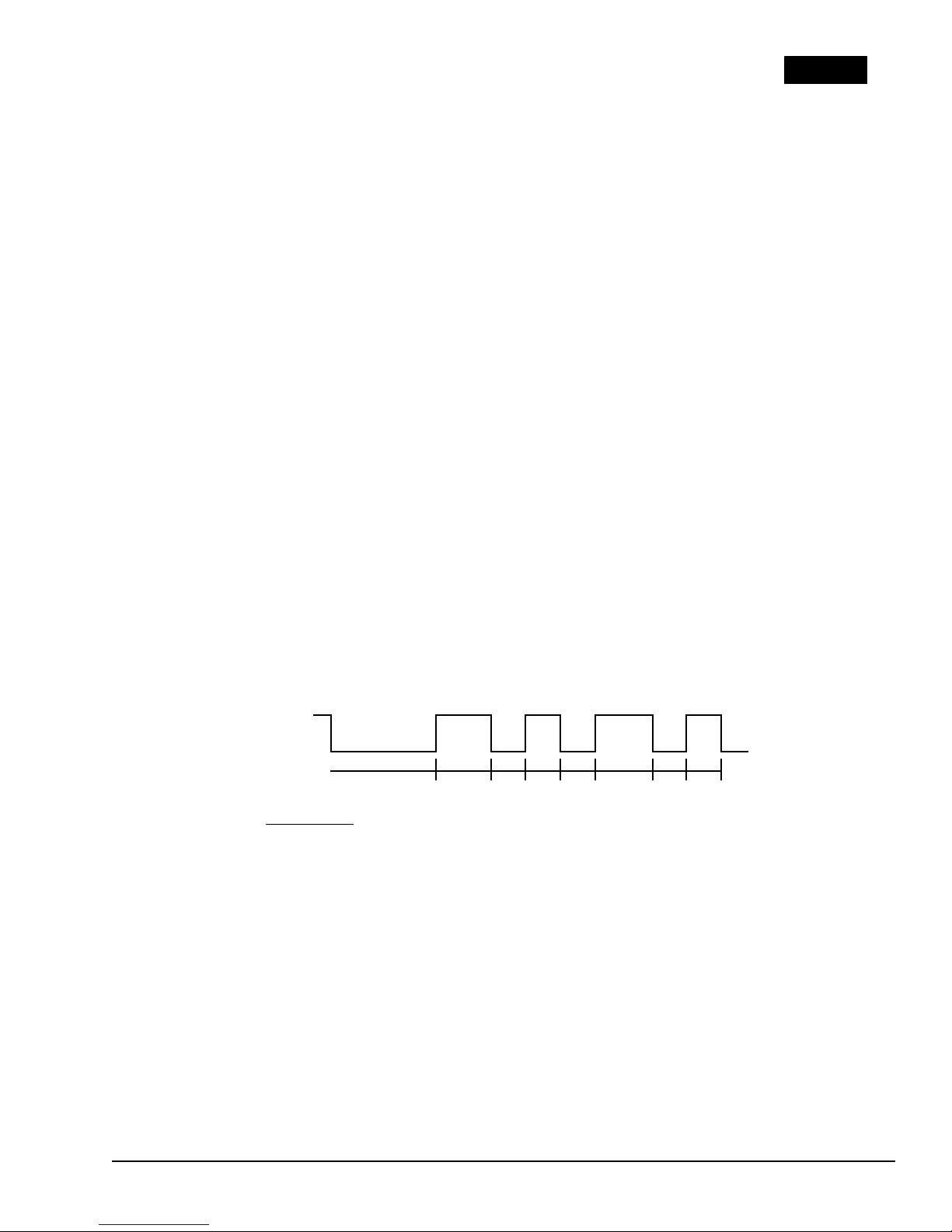
Check 1 When a power supply problem occurs, the DC IN indicator will flash repeatedly
with a 4-bit status that varies depending on the problem.
The DC IN indicator is off for two seconds and then it lights for either ½ second
(indicating a binary 0) or one full second (indicating a binary 1). There is a ½second interval between bits, with bit 0 (zero) or the least significant bit first and
ending with bit 3 (three) or the most significant bit.
For example, the following timing chart shows a status of 5h (0101). The timing
chart below is read from right to left.
Bit 0 Bit 1 Bit 2 Bit 3
1 0 1 0
ON
DC IN
OFF
2s 1s 0.5s 1s 0.5s
0.5s 0.5s 0.5s
Time
➝
The status and its meaning are described in Table 2-1.
However, when the DC IN indicator blinks at random, the AC adapter or charging
circuit may be damaged. In this case, replace the AC adapter with a new one. If the
2-9
problem still exists, perform Procedure 3.
current of charging current.
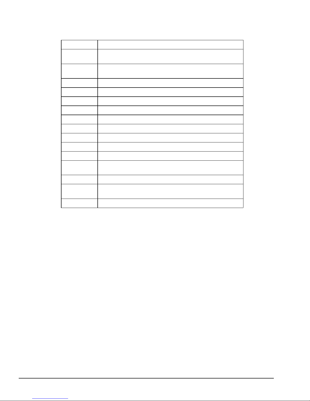
Table 2-1 Power supply error status
Status Meaning
1h Over voltage of AC ada pter output voltage. (More than
+18V±5%)
2h Abnorma l temperature in the system. (Less than -20°C or
more than 70°C.)
3h Abnormal charging. (The system cannot stop charging.)
4h Over current of charging current.
5h Abnormal charging voltage.
6h Abnorma l battery voltage.
7h Abnormal VCC (+ 5) voltage.
8h Abnormal R AMV (+5V for DRAM) voltage.
9h VEE (-9V) is shorted.
Ah VDD (+12V) is shorted.
Bh VDSP (+12V to +18V for FL) is shorted
Ch Turned off the Desk Station II before turning off the
T2000SXe.
Dh Battery terminal is shorted.
Eh Under voltage of A C adapter output voltage. (Less than
+18V±5%)
Fh Under
Check 2 When the DC IN indicator does not light, one or all of the following could be the
cause:
1. The AC adapter is damaged. Replace the AC adapter.
2. Fuse (F701) on the system board is bad. Replace the fuse.
3. The charge/+18V switching signal is not sent correctly. Replace the AC
adapter.
4. The AC adapter detecting circuit is damaged. Replace the AC adapter.
2-10

If the DC IN indicator problem still exists, perform Procedure 3.
2. The indicator labeled Battery lights yellow (while the system is charging the battery) or
lights green (when the battery pack is fully charged) if power is supplied from the AC
adapter when you connect the battery pack to the system and the system is off.
NOTE: The system automatically stops charging the battery when the battery pack
overheats.
If only the battery pack is connected to the system, this indicator does not light (indicating
the battery pack is in use, or the battery pack is not in use when the AC adapter is connected) or blinks red (indicating the battery is low). If the battery pack is completely
discharged, this indicator does not light.
(1) If the battery indicator blinks or does not glow when you connect the AC adapter to
the system and the system is off, see Check 3.
(2) If the battery indicator blinks when you disconnect the AC adapter from the system,
see Check 6.
NOTE: If both (1) and (2) above occur, check the power output circuits to the system.
Check 3 Make sure the battery pack is correctly connected to the system. If the problem still
exists, perform Check 4.
Check 4 Connect the AC adapter to the system and wait 30 minutes or so. If the problem still
exists, perform Check 5.
Check 5 Replace the battery pack with a recharged battery pack. If the problem still exists,
perform Procedure 2. Also, check the battery charge circuits.
Check 6 Make sure the battery pack is correctly connected to the system. If the problem still
exists, perform Check 7.
Check 7 Replace the battery pack with a known good one. If the problem still exists, perform
2-11

Procedure 2.
Procedure 2
Connector and Cable Check
The battery pack is connected to the system board with the battery cable. The cable may be disconnected or damaged. Refer to Part 4 for instructions on how to disassemble the T2000SXe and then
perform the following checks.
Check 1 Make sure the battery terminal cable is connected to the system board at PJ702.
Terminal System board PJ702
If this cable is disconnected, connect it and restart the system. If the problem still
exists, refer to Check 2.
Check 2 Recheck the cable using a multimeter. If the cable looks damaged, replace the
terminal assembly and restart the system. If the problem still exists, refer to Proce-
2-12

dure 3.
Procedure 3
Replacement Check
In the T2000SXe, the system board is connected with the power supply circuits. The LED board
(PCB FT2LEx) is connected with the indicator circuits. Either of these boards may be damaged.
Refer to Part 4 for instructions on how to disassemble the T2000SXe, and then perform the following checks.
Check 1 Replace the LED board with a new one and restart the system. If the problem still
exists, perform Check 2.
Check 2 Replace the system board with a new one. If the problem still exists, other units
2-13

may be damaged.
2.4 System Board Problem Isolation
Procedures
This section describes how to determine if the system board is causing the T2000SXe to operate
abnormally. Start with Procedure 1 and continue with the other procedures as instructed. The
procedures described in this section are:
Procedure 1: Message and Beep Sound Check
Procedure 2: Printer Port LED Check
2-14

Procedure 3: Test Program Check
Procedure 1
Message and Beep Sound Check
After the power is turned on, the system performs the Initial Reliability Test (IRT) which is stored
in the BIOS ROM on the system board. The IRT tests and initializes each IC on the system board.
If an error message appears on the screen, refer to Check 1. If nothing is displayed on the screen,
refer to Procedure 2.
Check 1 If the following error message appears on the screen briefly, the PRT/FDD port is
assigned as FDD-A and an external FDD is not attached to the PRT/FDD port.
Assign the PRT/FDD port as FDD-B or Printer using the Setup program, or
attach an external FDD. Then reboot the system.
*** FDD A is not installed ***
If another error message appears, perform Check 2.
Check 2 If the following error message appears on the screen, press the F1 key. Then ex-
ecute the setup operation. Detailed setup operation procedures are described in Part
3.
This program confirms the current T2000SXe system configuration and the configuration stored in RTC memory. If they are different, the following message will
appear.
*** Error in CMOS. Bad battery ***
Check system. Then press [F1] key.
*** Error in CMOS. Bad check sum ***
Check system. Then press [F1] key.
*** Error in CMOS. Bad memory configuration ***
Check system. Then press [F1] key.
*** Error in CMOS. Bad time function ***
Check system. Then press [F1] key.
2-15

If another error message appears, refer to Check 3.
Check 3 If the following message appears, and the status of the printer port LED is F4h to
F6h, replace the system board. Otherwise, press any key. At this time the resumed
data will be erased.
WARNING: RESUME FAILURE.
PRESS ANY KEY TO CONTINUE.
WARNING: DATA IN HARD RAM WAS LOST
YOU MUST FORMAT HARD RAM BEFORE USE
PRESS ANY KEY TO CONTINUE
If another error message appears, refer to Check 4.
Check 4 The IRT program tests the system board. If an error occurs in the IRT program, the
error message appears on the screen and beep sounds are generated.
If the following message appears, replace the system board. Otherwise, refer to
Check 5.
ERROR INTERRUPT CONTROLLER #1
ERROR INTERRUPT CONTROLLER #2
MEMORY VERIFY ERROR AT xxxx:xxxx FOUND xxxx
EXPECTED xxxx
ERROR INTERRUPTS AND STUCK NMI
ERROR PROTECT MODE
ERROR PROCESSOR EXCEPTIONAL INTERRUPTS
Check 5 If the following message is displayed on the screen, refer to the Hard Disk Drive
Problem Isolation Procedures in Section 2.6.
If the following error message does not appear and the beep sounds do not occur,
refer to Procedure 2.
ERROR ENCOUNTERED INITIALIZING HARD DISK DRIVE
2-16

ERROR INITIALIZING HARD DISK CONTROLLER
1Ah 9Ah PIC channel 2 test 3 beeps continue
Procedure 2
Printer Port LED Check
The printer port LED displays the IRT program status and error status as a hexadecimal value after
the T2000SXe is turned on.
1. Connect the printer port LED to the printer port.
2. After turning the system on, read the LED status from left to right as you are facing
the back of the computer.
3. If the final LED status is FFh, refer to Procedure 3. If the final LED status matches
one of the error status codes in Table 2-2, replace the system board.
Normal
Status
Error
Status
Meaning Process
00h C0h CPU s elf-test Ha lt
01h 81h CPU test 1 (flag test) Ha lt
02h 82h KBIC IBF/OBF test, video initialization Halt
03h 83h KBIC IBF test (0AAh command) Ha lt
04h 84h KBIC OBF test (55h check) Halt
05h Reserved
06h LSI initialization (DM A, PIT, PIC, RTC) Continue
07h 87h CPU test 2 (registers) Halt
08h RTC initia lization (regis ter B) Continue
09h 89h ROM checksum test (64KB) Halt
0Ah 8Ah Video initializ ation Ha lt
0Bh Reserved
0Ch Reserved
0Dh 8Dh PIT cha nnel 2 test and its initialization Ha lt
0Eh Reserved
0Fh 8Fh CMOS RAM test Ha lt
10h 90h DMA channel 0 test Ha lt
11h 91h DMA channel 1 test Ha lt
12h 92h DMA page register test Ha lt
13h 93h KBSC test and its initialization Halt
14h 94h Memory refresh test Ha lt
A7h Backup RAM test Ha lt
14h Protect mode te st Halt
15h 95h First 64KB RAM test Ha lt
16h Interrupt vector setup Continue
17h 97h Video option test Halt
18h 98h V-RAM test Ha lt
19h 99h PIC channel 1 test 3 beeps continue
2-17

Table 2-2 Normal status and error status of the printer port LED
26h A6h Protect mode exception test 3 beeps continue
Internal expansion memory has been corrupted.
Table 2-2 Normal status and error status of the printer port LED (continued)
Normal
Status
Error
Status
Meaning Process
1Bh 9Bh CMOS batte ry test 1 beep key wait
1Ch Reserved Continue
1Dh 9Dh Setup RAM size from CMOS (413h) Continue
1Eh 9Eh Size conventional RAM Continue
1Fh 9Fh Conventional RA M test 3 beeps continue
20h A0h PIC ch1/ch2 test Continue
21h A1h NMI check Continue
22h A2h Interrupt proces s test (INT8) 3 beeps continue
23h A3h Protect mode test 3 beeps continue
24h A4h Size extended RAM Continue
25h A5h Conventional and extended RAM test 3 beeps continue
NOTE: If the error occurs on the 19h to 24h normal status, the system does not halt.
The error message remains on the screen and when the IRT program is finished, these
error messages are erased.
Status Explanation
F1h An FDD was running when the power was turned off.
Power was turned off while the IRT was running.
The hardware reset switch was pressed.
An external display card was attached when the power
was turned off.
An external expansion memory card was attached when
the power was turned off.
F2h An external display card was attached while the power
was turned off.
F3h An internal display card was changed while the power
was turned off.
F4h Backup RAM has been corrupted.
The backup RAM checksum, system RAM checksum,
V-RAM checksum, or expansion memory checksum in
backup RAM has been corrupted.
F5h System RAM has been corrupted.
F6h V-RAM has been corrupted.
F7h
2-18

The table below lists the resume errors and the associated error status codes.
Procedure 3
Test Program Check
The Diagnostic Test function in the T2000SXe Diagnostic Program has several tests for testing the
T2000SXe system board. Perform the following tests.
❑ System test
❑ Memory test
❑ Display test
❑ Printer test
❑ ASYNC test
❑ Real timer test
Refer to Part 3 for detailed instructions about these tests.
2-19

If an error is detected during the T2000SXe Diagnostic Program, replace the system board. If the
problem still exists, check the other FRUs in the T2000SXe.
2.5 Floppy Disk Drive Problem Isolation
Procedures
This section describes how to determine if the floppy disk drive is causing the T2000SXe to operate abnormally. Start with Procedure 1 and continue with the other procedures as instructed. The
procedures described in this section are:
Procedure 1: Message Check
Procedure 2: Format Check
Procedure 3: Test Program Check
2-20

Procedure 4: Connector Check
Procedure 1
Message Check
Insert the Toshiba MS-DOS system disk in the FDD and turn on the power. If the T2000SXe loads
Toshiba MS-DOS normally, refer to Procedure 2.
If Toshiba MS-DOS does not load normally, the following message or a similar message will
appear on the screen. Refer to Procedure 4.
Place system disk in drive.
Press any key when ready.
2-21

Non-System disk or disk error
Replace and press any key when ready
Procedure 2
Format Check
Format a floppy disk using the Toshiba MS-DOS FORMAT command.
If the floppy disk does not format correctly, perform the following checks.
Check 1 Make sure the FDD indicator lights. If it does not light, refer to Procedure 4. If it
lights, refer to Check 2.
Check 2 Make sure the Toshiba MS-DOS FORMAT command was used correctly.
When the media type is 2DD, use the FORMAT/3 command.
When the media type is 2HD, use the FORMAT command.
If the FORMAT command was used correctly, refer to Check 3.
If the FORMAT command was not used correctly, try again. If the problem still
exists, refer to Check 3.
2-22

Check 3 Clean the read/write head using the 3.5-inch FDD cleaning kit. If the problem still
EEh Write buffe r error
exists, refer to Procedure 3.
Procedure 3
Test Program Check
The FDD test program is stored on the T2000SXe Diagnostics Disk. After loading Toshiba MSDOS, run the Diagnostic Program (TESTCE20). Refer to Part 3 for detailed instructions about the
FDD test.
Insert a formatted floppy disk and then start the FDD test. The error code and status are described
in Table 2-3.
If an error occurs, refer to Check 1.
Code Status
Table 2-3 FDD error code and status
01h Bad command
02h Address mark not found
03h Write protected
04h Record not found
06h Media removed on dual attach card
08h DMA overrun error
09h DMA bounda ry error
10h CRC error
20h FDC error
40h Seek error
60h FDD not drive
80h Time out e rror (Not ready)
Check 1 If the Write protected message appears, remove the write protect tab on the
floppy disk. If any other error message appears, refer to Check 2.
2-23

Check 2 Make sure the floppy disk is formatted correctly. If it is correct, refer to Procedure
4.
Procedure 4
Connector Check
The FDD is connected to the system unit by the FDD cable. Disassemble the system unit and
check the FDD. Refer to Part 4 for instructions on how to disassemble the system unit and then
perform the following checks.
Check 1 Make sure the FDD cable is firmly connected to the system board at PJ16.
If this cable is disconnected, connect it to the system unit and refer back to Procedures 2 and 3. If the problem still exists, refer to Check 2.
Check 2 The FDD may be defective. Replace the FDD with a new one and refer back to
2-24

Procedures 2 and 3. If the problem still exists, refer to Check 3.
Check 3 The system board may be causing the problem. Replace it with a new system board.
2.6 Hard Disk Drive Problem Isolation
Procedures
This section describes how to determine if the hard disk drive is defective. Start with Procedure 1
and continue with the other procedures as instructed. The procedures described in this section are:
Procedure 1: Message Check
Procedure 2: Logical Format Check
Procedure 3: Test Program Check
Procedure 4: Connector Check
CAUTION: The contents of the hard disk will be erased when the HDD Problem Isola-
2-25

tion Procedures are executed. Before continuing, transfer the contents of the hard disk
to floppy disks. This can be done with the Toshiba MS-DOS BACKUP command. Refer
to the Toshiba MS-DOS manual for details.
Procedure 1
Message Check
When the power switch is turned on, the following message may appear on the screen.
If the following message appears, refer to Procedure 4.
ERROR ENCOUNTERED INITIALIZING HARD DISK DRIVE
ERROR INITIALIZING HARD DISK CONTROLLER
2-26

If the above message does not appear, refer to Procedure 2.
Procedure 2
Logical Format Check
Using the Toshiba MS-DOS system disk, partition the hard disk using the FDISK command. Then
format the hard disk using the /s switch after the FORMAT command to transfer the system program.
2-27

If normal operation is restored, the HDD is OK. If normal operation is not restored, refer to Proce-
E0h Status error
dure 3.
Procedure 3
Test Program Check
The HDD test program is stored on the T2000SXe Diagnostics Disk. After loading Toshiba MSDOS, run the Diagnostic Program (TESTCE20) and perform the HDD test. Refer to Part 3 for
detailed instructions about the HDD test.
If an error occurs during the HDD testing, an error code and status will be displayed; refer to
Procedure 4. The HDD error code and descriptions are described in Table 2-4. If an error code is
not generated, the HDD is OK.
Code Status
01h Bad command error
02h Bad address error
04h Record not found
05h HDC not reset
07h Drive not initialize
09h DMA bounda ry error
0Ah Bad s ector error
0Bh Bad tra ck error
10h ECC error
11h ECC recover ena ble
20h HDC error
40h Seek error
80h Time out error
AAh Drive not ready
BBh Undefined
CCh Write fault
2-28

Table 2-4 HDD error code and status
Procedure 4
Connector Check
The HDD is connected to the system board by the HDD board (PCB FT2HDx). Disassemble the
system unit and check the HDD. Refer to Part 4 for instructions on how to disassemble the computer and then perform the following checks.
Check 1 Make sure the HDD board (orange flat cable) is firmly connected to the system
board and HDD.
If the board is disconnected, firmly reconnect it and refer back to Procedures 2 and
3. If the problem still exists, refer to Check 2.
Check 2 The HDD may be defective. Replace the HDD unit with a new one. If the error still
occurs, refer to Check 3.
Check 3 The system board may be damaged. Replace the system board with a new one. If
the error still occurs, refer to Check 4.
2-29

Check 4 The HDD board may be damaged. Replace the HDD board with a new one.
2.7 Keyboard Problem Isolation
Procedures
This section describes how to determine if the keyboard is causing the T2000SXe to operate abnormally. Start with Procedure 1 and continue with the other procedures as instructed. The procedures described in this section are:
Procedure 1: Test Program Check
2-30

Procedure 2: Connector Check
Procedure 1
Test Program Check
The keyboard test program is stored on the T2000SXe Diagnostics Disk. After loading Toshiba
MS-DOS, run the Diagnostic Program (TESTCE20) and perform the keyboard test. Refer to Part 3
for detailed instructions about the keyboard test.
If an error occurs, refer to Procedure 2.
2-31

If an error does not occur, the keyboard is OK.
Procedure 2
Connector Check
The keyboard is connected to the system board by 8-pin and 12-pin flat cables. Disassemble the
system unit and check the keyboard cables. Refer to Part 4 for instruction on how to disassemble
the system unit and then perform the following checks.
Check 1 Make sure the following cables are firmly connected to the system board.
Keyboard cable System board PJ7
System board PJ8
If these cables are not connected, connect them and refer back to Procedure 1. If the
problem still exists, refer to Check 2.
Check 2 The keyboard or keyboard cables may be damaged. Replace the keyboard with a
new one, and refer back to Procedure 1. If the problem still exists, refer to Check 3.
Check 3 The keyboard controller on the system board may be damaged. Replace the system
2-32

board with a new one.
2.8 Display Problem Isolation Procedures
This section describes how to determine if the display is causing the T2000SXe to operate abnormally. Start with Procedure 1 and continue with the other procedures as instructed. The procedures described in this section are:
Procedure 1: Brightness and Contrast Volume Check
Procedure 2: Test Program Check
Procedure 3: Connector Check
2-33

Procedure 4: Replacement Check
Procedure 1
Brightness and Contrast Volume Check
The brightness and contrast dials are on the right side of the display unit. Use these dials to adjust
the display screen to your satisfaction.
If only the brightness does not change, refer to Procedure 3.
If only the contrast does not change, refer to Procedure 3.
2-34

If both the brightness and contrast do not change, refer to Procedure 2.
Procedure 2
Test Program Check
The display test program is stored on the T2000SXe Diagnostics Disk. This program checks the
display controller on the system board. After loading Toshiba MS-DOS, run the Diagnostic Program (TESTCE20). Refer to Part 3 for detailed instructions about the display test.
If an error is detected, refer to Procedure 3.
2-35

If an error is not detected, the display is OK.
Procedure 3
Connector Check
The display unit has an LCD module, FL (Fluorescent Lamp), and FL inverter. The LCD module
and FL inverter are connected to the system board with the LCD cable. The LED board (PCB
FT2LEx) is connected directly to the system board. Either or both of these cables may be disconnected from the system board.
Disassemble the display unit and check these connectors. Refer to Part 4 for instruction on how to
disassemble the system unit.
System board PJ12 LCD module CN1
LCD module CN2
System board PJ9 LED board
If these connectors are not connected, connect them and refer back to Procedures 1 and 2. If the
2-36

problem still exists, refer to Procedure 4.
Procedure 4
Replacement Check
In the T2000SXe, the FL inverter, LCD module, and system board are connected with the display
circuits. Any of these units may be damaged. Refer to Part 4 for instructions on how to disassemble the system unit and then perform the following checks.
Check 1 Replace the FL inverter with a new one and recheck the display. If the problem still
exists, refer to Check 2.
Check 2 Replace the LCD module with a new one and recheck the display. If the problem
still exists, refer to Check 3.
Check 3 The system board may be damaged. Replace the system board with a new one and
recheck the display. If the problem still exists, refer to Check 4.
Check 4 The LED board may be damaged. Replace the LED board with a new one.
2-37

This page intentionally left blank
2-38

Part 3
Tests and Diagnostics
3-1

This page intentionally left blank
3-2

Contents
3.1 General ....................................................................................................................... 3-5
3.2 Using the T2000SXe Diagnostic Program................................................................... 3-6
3.3 Subtest Names ............................................................................................................ 3-9
3.4 System Test .............................................................................................................. 3-11
3.5 Memory Test ............................................................................................................. 3-12
3.6 Keyboard Test........................................................................................................... 3-14
3.7 Display Test.............................................................................................................. 3-15
3.8 Floppy Disk Test....................................................................................................... 3-21
3.9 Printer Test ............................................................................................................... 3-23
3.10 ASYNC Test ............................................................................................................. 3-25
3.11 Hard Disk Test .......................................................................................................... 3-27
3.12 Real Timer Test ........................................................................................................ 3-31
3.13 NDP Test .................................................................................................................. 3-32
3.14 Error Codes and Error Status Names......................................................................... 3-33
3.15 Hard Disk Test Detail Status..................................................................................... 3-35
3.16 Hard Disk Format ..................................................................................................... 3-37
3.16.1 Program Description ..................................................................................... 3-37
3.16.2 Operations ..................................................................................................... 3-38
3.17 Head Cleaning ........................................................................................................... 3-41
3.17.1 Program Description ..................................................................................... 3-41
3.17.2 Operations ..................................................................................................... 3-41
3-3

3.18 Log Utilities .............................................................................................................. 3-42
3.18.1 Program Description ..................................................................................... 3-42
3.18.2 Operations ..................................................................................................... 3-42
3.19 Running Test............................................................................................................. 3-44
3.19.1 Program Description ..................................................................................... 3-44
3.19.2 Operations ..................................................................................................... 3-44
3.20 FDD Utilities ............................................................................................................ 3-45
3.20.1 Program Description ..................................................................................... 3-45
3.20.2 Operations ..................................................................................................... 3-46
3.21 System Configuration ............................................................................................... 3-50
3.21.1 Program Description ..................................................................................... 3-50
3.21.2 Operations ..................................................................................................... 3-50
3.22 SETUP ...................................................................................................................... 3-51
3.22.1 Program Description ..................................................................................... 3-51
3.22.2 Accessing the SETUP .................................................................................... 3-52
3.22.3 Changing SETUP Values ............................................................................... 3-53
3.22.4 SETUP Descriptions...................................................................................... 3-54
Tables
Table 3-1 Subtest names .................................................................................................. 3-9
Table 3-2 Hardware status bit........................................................................................ 3-11
Table 3-3 Error codes and error status names ................................................................ 3-33
Table 3-4 HDC status register contents ......................................................................... 3-35
Table 3-5 Error register contents ................................................................................... 3-36
Table 3-6 Hard disk formatting sequence ...................................................................... 3-37
3-4

3.1 General
This part explains how to use the T2000SXe Diagnostic Program (TESTCE20) which tests the
functions of all the T2000SXe hardware modules. This program is located on the T2000SXe
Diagnostic Diskette. The Diagnostic Program is composed of 18 programs divided into the Service Program Module (DIAGNOSTICS MENU) and the Test Program Module (DIAGNOSTIC
TEST MENU).
The Service Program Module provides the following eight functions:
1. DIAGNOSTIC TEST
2. HARD DISK FORMAT
3. HEAD CLEANING
4. LOG UTILITIES
5. RUNNING TEST
6. FDD UTILITIES
7. SYSTEM CONFIGURATION
8. SETUP
The Test Program Module contains the following ten tests. These are all located within the Diagnostic Test function of the Service Program Module.
1. SYSTEM TEST
2. MEMORY TEST
3. KEYBOARD TEST
4. DISPLAY TEST
5. FLOPPY DISK TEST
6. PRINTER TEST
7. ASYNC TEST
8. HARD DISK TEST
9. REAL TIMER TEST
10. NDP TEST
To execute the T2000SXe Diagnostic Program you will need the following:
❑ T2000SXe Diagnostics Diskette
❑ Formatted work disk for the FDD test
❑ Cleaning disk kit to clean the FDD heads
❑ Printer wraparound connector for the printer wraparound test
❑ RS-232-C wraparound connector for the ASYNC wraparound test
The following sections detail the tests within the Diagnostic Test function of the Service Program
Module. Refer to Sections 3.16 through 3.22 for detailed information on the remaining seven
Service Program functions.
3-5

3.2 Using the T2000SXe Diagnostic
Program
To start the T2000SXe Diagnostic Program, follow these steps:
1. Make sure the computer is loaded with Toshiba MS-DOS version 3.3 or 4.0. Turn on the
T2000SXe and insert the T2000SXe Diagnostics Diskette in the floppy disk drive.
2. Change to the A drive. Then type A:TESTCE20 and press Enter.
3. The DIAGNOSTICS MENU will be displayed as shown below.
TOSHIBA personal computer T2000SXe DIAGNOSTICS
version x.xx (c) copyright TOSHIBA Corp. 1991
DIAGNOSTICS MENU :
1 - DIAGNOSTIC TEST
2 - HARD DISK FORMAT
3 4 - HEAD CLEANING
5 - LOG UTILITIES
6 - RUNNING TEST
7 - FDD UTILITIES
8 - SYSTEM CONFIGURATION
9 - EXIT TO MS-DOS
0 - SETUP
PRESS [0] - [9] KEY
NOTE: To exit the Diagnostic Test function, press Ctrl + C. If a test is in progress,
press Ctrl + Break to exit the test.
3-6

4. To execute the Diagnostic Test function from the DIAGNOSTICS MENU, type 1 and press
Enter. The following DIAGNOSTIC TEST MENU will be displayed, listing the ten tests.
TOSHIBA personal computer T2000SXe DIAGNOSTICS
version x.xx (c) copyright TOSHIBA Corp. 1991
DIAGNOSTIC TEST MENU :
1 - SYSTEM TEST
2 - MEMORY TEST
3 - KEYBOARD TEST
4 - DISPLAY TEST
5 - FLOPPY DISK TEST
6 - PRINTER TEST
7 - ASYNC TEST
8 - HARD DISK TEST
9 - REAL TIMER TEST
10 - NDP TEST
88 - FDD & HDD ERROR RETRY COUNT SET
99 - EXIT TO DIAGNOSTICS MENU
PRESS [1] - [99] KEY
Diagnostic Tests 1 through 10 are discussed in Sections 3.4 through 3.13. Test menu option
88 sets the floppy disk drive and hard disk drive error retry count. Option 99 exits the
DIAGNOSTIC TEST MENU and returns you to the DIAGNOSTICS MENU.
5. Enter the desired test number from the DIAGNOSTIC TEST MENU and press Enter. The
following message will be displayed.
SYSTEM TEST XXXXXXX
T2000SXe DIAGNOSTIC TEST Vx.xx
[Ctrl]+[Break] ; test and
[Ctrl]+[C] ; key stop
SUB-TEST : XX
PASS COUNT: XXXXX ERROR COUNT: XXXXX
WRITE DATA: XX READ DATA : XX
ADDRESS : XXXXXX STATUS : XXX
SUB-TEST MENU :
01 - ROM checksum
02 - HW status
99 - Exit to DIAGNOSTIC TEST MENU
SELECT SUB-TEST NUMBER ?
NOTE: The message displayed by your T2000SXe may be slightly different than the one
shown above.
3-7

6. Enter the desired subtest number from the subtest menu and press Enter. The following
message will appear.
TEST LOOP (1:YES/2:NO) ?
Selecting YES increases the pass counter by one each time the test cycle ends and then
restarts the test cycle.
Selecting NO returns you to the subtest menu after the test is completed.
7. Type in 1 or 2 for the Test Loop and press Enter. The following message will appear.
ERROR STOP (1:YES/2:NO) ?
Selecting YES stops the test program when an error is found and displays the operation
guide on the right side of the display screen as shown below.
ERROR STATUS NAME [[ HALT OPERATION ]]
1: Test End
2: Continue
3: Retry
1: Terminates the test program execution and exits to the subtest menu.
2: Continues the test.
3: Restarts the test from the beginning of the test.
Selecting NO displays the error status, increases the error counter by one, and resumes the
test.
8. Type in 1 or 2 for the Error stop and press Enter to execute the subtest chosen from the
subtest menu. Table 3-1 in Section 3.3 lists the subtests available for each test on the
DIAGNOSTIC TEST MENU.
Table 3-3 in Section 3.14 describes the error codes and error status for each error.
3-8

3.3 Subtest Names
06 Interrupt test
Table 3-1 describes the subtest for each test program in the Test Program Module.
Table 3-1 Subtest names
Test No.
1 SYSTEM
2 MEMORY
3 KEYB OARD
4 DISPLAY
5 FDD
6 PRINTER
7 ASYNC
Test name Subte st
Subtest name
No.
01 R OM checksum
02 HW status
01 R AM constant data
02 R AM address pattern data
03 R AM refresh
04 Protected mode
05 M emory module
06 B ackup memory
07 Hard-RAM
01 Pressed key display (86/88)
02 Pressed key code display
01 VRAM read/write
02 C haracter attributes
03 C haracter set
04 80*25/30 Characte r display
05 320*200 Graphics display
06 640*200 Graphics display
07 640*350/400/480 G raphics display
08 Display page
09 " H" pattern display/Border color
10 LED / DAC pallet
01 Sequential read
02 Sequential read/write
03 Random address/data
04 Write specified address
05 Read specified address
01 R ipple pattern
02 Function
03 Wrap around
01 Wrap around (board)
02 B oard (#1) <=> board (#2)
03 Point to point (send)
04 Point to point (receive)
05 C ard modem loopback (1200BPS)
3-9

Table 3-1 Subtest names (continued)
10 NDP 01 NDP test
Test No. Test name Subtest
No.
01 Sequential read
02 Address uniquence (uniqueness)
03 Random address/data
04 C ross talk & peek (peak) shift
8 HDD
05 Write/read/compare (CE)
06 Write specified address
07 Read specified address
08 ECC circuit
09 Sequential write
10 W-R-C spe cified address
01 R eal time
9 REAL TIM ER
02 B ackup memory
03 R eal time carry
Subtest name
3-10

3.4 System Test
0 Internal FDD 2DD 2HD
Subtest 01 ROM checksum
This test performs a ROM checksum test on the T2000SXe’s system board from
address F0000h - FFFFFh (64KB).
Subtest 02 HW status
This test reads and displays the T2000SXe’s hardware status as shown below.
76543210
H/W status = 10001000
Bit7 — =
Bit6 — CPU clock = 20MHZ
Bit5 — Notch signal = 2HD
Bit4 — FDD type = 2MB
Bit3 — =
Bit2 — Drive A/B = Ext. = B
Bit1 — External FDD = OFF
Bit0 — Internal FDD = 2HD
Once this information is displayed, press Ctrl + Break to return to the SYSTEM
TEST menu. There is a slight delay of about 15 seconds before the Ctrl + Break
keys can be pressed.
Table 3-2 describes the hardware bit status.
Table 3-2 Hardware bit status
Bit H/W s tatus 1 0
7 Reserved
6 CPU clock speed 10 MHz 20 MHz
5 Media type 2DD 2HD
4 FDD type 1 M B 2 MB
3 Reserved
2 Drive A/B B A
1 External FDD ON OFF
3-11

3.5 Memory Test
Subtest 01 RAM constant data
This subtest writes constant data to conventional memory (0 to 640KB), then reads
and compares it with the original data.
The constant data is FFFFh, AAAAh, 5555h, 0101h, and 0000h.
Subtest 02 RAM address pattern data
This subtest writes address pattern data created by eXclusive-ORing (XORing) the
address segment and address offset to conventional memory (0 to 640KB), then
reads and compares it with the original data.
Subtest 03 RAM refresh (real mode)
This subtest writes 256-byte units of constant data to conventional memory (0 to
640KB), then reads and compares it with the original data.
The constant data is AAAAh and 5555h.
There is a delay between the write and the read operations.
Subtest 04 Protected mode
This subtest writes constant data and address data to extended memory (addressed
100000h to the max.), then reads and compares it with the original data.
The constant data is FFh, AAh, 55h, and 00h.
Subtest 05 Memory module
NOTE: To execute the this subtest, an optional memory card must be installed in the
T2000SXe.
This subtest is the same as subtest 04; it is used for testing an optional memory card.
Memory module capacity is 2MB, 4MB, and 8MB.
After selecting subtest 05, the following message will be displayed.
Extended memory size (1:1MB,2:2MB,3:4MB,4:8MB) ?
Select the number that corresponds to the memory card installed in the T2000SXe.
3-12

Subtest 06 Backup memory
This subtest writes constant data to memory from address E8000h to EFFFFh, then
reads and compares it with the original data.
The constant data is 00h, 55h, AAh, and FFh.
Subtest 07 Hard-RAM
NOTE: To execute this subtest, Hard-RAM must be set up on the system.
This subtest writes word units of constant data to memory (address E0000h to
E7FFFh), then reads and compares it with the original data.
The constant data is 00h, 55h, AAh, and FFh.
Also, this subtest executes the paging test on page data.
3-13

3.6 Keyboard Test
Subtest 01 Pressed key display (86/88)
NOTE: Make sure the Num Lock key is off. If the Num Lock key is on, this subtest
cannot be executed.
The keyboard layout, as shown below, is drawn on the display. When any key is
pressed, the corresponding key on the screen is changed to the “*” (asterisk) character.
When a key is held down, the display will blink indicating that the auto-repeat
function is enabled.
KEYBOARD TEST IN PROGRESS 301000
[Print:Alt+SysReq , Pause:Ctrl+Break]
IF TEST OK, PRESS [DEL] THEN [ENTER] KEY
Subtest 02 Pressed key code display
When a key is pressed, the scan code, character code, and key top name are displayed on the screen in the format shown below.
The Ins, Caps Lock, Num Lock, Scroll Lock, Alt, Ctrl, Left Shift, and Right
Shift keys are displayed in reverse video when pressed. The scan codes, character
codes, and key top names are listed in Appendix D.
KEYBOARD TEST IN PROGRESS 302000
Scan code =
Character code =
Keytop =
Ins Lock Caps Lock Num Lock Scroll Lock
Alt Ctrl Left Shift Right Shift
PRESS [ENTER] KEY
3-14

3.7 Display Test
Subtest 01 VRAM read/write
This subtest writes constant data and address data to video RAM (256KB), then
reads the data written and compares it with the original data.
The constant data is FFFFh, AAAAh, 5555h, and 0000h.
Subtest 02 Character attributes (mode 1, 13h)
This subtest shows the following display modes and displays the foreground colors
and intensified colors (16 colors or 16 levels of gray) using black, blue, red, magenta, green, cyan, yellow, and white from the color display.
Normal
Intensified
Reverse
Blinking
The display below appears on the screen when this subtest is selected.
CHARACTER ATTRIBUTES
NEXT LINE SHOWS NORMAL DISPLAY.
NNNNNNNNNNNNNNNNNNNNNNNNNNNNNN
NEXT LINE SHOWS INTENSIFIED DISPLAY.
IIIIIIIIIIIIIIIIIIIIIIIIIIIIII
NEXT LINE SHOWS REVERSE DISPLAY.
RRRRRRRRRRRRRRRRRRRRRRRRRRRRRR
NEXT LINE SHOWS BLINKING DISPLAY
BBBBBBBBBBBBBBBBBBBBBBBBBBBBBB
3-15

After pressing Enter, 16 colors or 16 levels of gray for mode 13h are displayed as
shown below.
320*200 GRAPHICS DISPLAY [ 13 ]
To exit this subtest and return to the DISPLAY TEST menu, press Ctrl + Break.
Subtest 03 Character set
In this subtest the character set (00h to FFh) is displayed in the 40x25 character
mode as shown below.
CHARACTER SET IN 40*25
PRESS [ENTER] KEY
To exit this subtest and return to the DISPLAY TEST menu, press Ctrl + Break.
3-16

Subtest 04 80x25 and 80x30 Character display (mode 12)
In this subtest, the character string is displayed shifting one character line by line in
the 80x25 and 80x30 character mode as shown below.
80*XX CHARACTER DISPLAY
012345678901234567890123456789012345678901234567890123456789012345678901234567
!”#$%&’()*+,-./0123456789:;<=>?@ABCDEFGHIJKLMNOPQRSTUVWXYZ[\]^_‘abcdefghijklm
!”#$%&’()*+,-./0123456789:;<=>?@ABCDEFGHIJKLMNOPQRSTUVWXYZ[\]^_‘abcdefghijklmn
“#$%&’()*+,-./0123456789:;<=>?@ABCDEFGHIJKLMNOPQRSTUVWXYZ[\]^_`abcdefghijklmno
#$%&’()*+,-./0123456789:;<=>?@ABCDEFGHIJKLMNOPQRSTUVWXYZ[\]^_‘abcdefghijklmnop
$%&’()*+,-./0123456789:;<=>?@ABCDEFGHIJKLMNOPQRSTUVWXYZ[\]^_‘abcdefghijklmnopq
%&’()*+,-./0123456789:;<=>?@ABCDEFGHIJKLMNOPQRSTUVWXYZ[\]^_‘abcdefghijklmnopqr
&’()*+,-./0123456789:;<=>?@ABCDEFGHIJKLMNOPQRSTUVWXYZ[\]^_‘abcdefghijklmnopqrs
‘()*+,-./0123456789:;<=>?@ABCDEFGHIJKLMNOPQRSTUVWXYZ[\]^_`abcdefghijklmnopqrst
()*+,-./0123456789:;<=>?@ABCDEFGHIJKLMNOPQRSTUVWXYZ[\]^_‘abcdefghijklmnopqrstu
)*+,-./0123456789:;<=>?@ABCDEFGHIJKLMNOPQRSTUVWXYZ[\]^_‘abcdefghijklmnopqrstuv
*+,-./0123456789:;<=>?@ABCDEFGHIJKLMNOPQRSTUVWXYZ[\]^_‘abcdefghijklmnopqrstuvw
+,-./0123456789:;<=>?@ABCDEFGHIJKLMNOPQRSTUVWXYZ[\]^_‘abcdefghijklmnopqrstuvwx
,-./0123456789:;<=>?@ABCDEFGHIJKLMNOPQRSTUVWXYZ[\]^_‘abcdefghijklmnopqrstuvwxy
-./0123456789:;<=>?@ABCDEFGHIJKLMNOPQRSTUVWXYZ[\]^_‘abcdefghijklmnopqrstuvwxyz
./0123456789:;<=>?@ABCDEFGHIJKLMNOPQRSTUVWXYZ[\]^_‘abcdefghijklmnopqrstuvwxyz{
/0123456789:;<=>?@ABCDEFGHIJKLMNOPQRSTUVWXYZ[\]^_‘abcdefghijklmnopqrstuvwxyz{|
0123456789:;<=>?@ABCDEFGHIJKLMNOPQRSTUVWXYZ[\]^_‘abcdefghijklmnopqrstuvwxyz{|}
123456789:;<=>?@ABCDEFGHIJKLMNOPQRSTUVWXYZ[\]^_‘abcdefghijklmnopqrstuvwxyz{|}~
23456789:;<=>?@ABCDEFGHIJKLMNOPQRSTUVWXYZ[\]^_‘abcdefghijklmnopqrstuvwxyz{|}~•
3456789:;<=>?@ABCDEFGHIJKLMNOPQRSTUVWXYZ[\]^_‘abcdefghijklmnopqrstuvwxyz{|}~•Ç
456789:;<=>?@ABCDEFGHIJKLMNOPQRSTUVWXYZ[\]^_‘abcdefghijklmnopqrstuvwxyz{|}~•Çü
PRESS [ENTER] KEY
To exit this subtest and return to the DISPLAY TEST menu, press Ctrl + Break.
Subtest 05 320x200 Graphics display (mode 4, D)
This subtest displays the following two color sets for the color display in the
320x200 dots graphics mode 4 and D as shown below.
Color set 1: Green, Red, Yellow
Color set 2: Cyan, Magenta, White
320*200 GRAPHICS DISPLAY
COLOR SET X : [X]
To exit this subtest and return to the DISPLAY TEST menu, press Ctrl + Break.
3-17

Subtest 06 640x200 Graphics display (mode 6, E)
This subtest displays the even dots, odd dots, and all dots blocks in the 640x200 dots
graphics mode 6 and E as shown below.
640*200 GRAPHICS DISPLAY : [X]
EVEN DOTS ODD DOTS ALL DOTS
DRIVEN DRIVEN DRIVEN
PRESS [ENTER] KEY
To exit this subtest and return to the DISPLAY TEST menu, press Ctrl + Break.
Subtest 07 640x350/400/480 Graphics display (mode 10, 74, 12)
This subtest displays the even dots, odd dots, and all dots blocks in the 640x350 and
640x480 dots graphics mode 10 and 12 as shown below.
640*XXX GRAPHICS DISPLAY : [XX]
EVEN DOTS ODD DOTS ALL DOTS
DRIVEN DRIVEN DRIVEN
PRESS [ENTER] KEY
To exit this subtest and return to the DISPLAY TEST menu, press Ctrl + Break.
3-18

Subtest 08 Display page
This subtest confirms that the pages can be changed in order from page 0 through
page 7 in the 40x25 character mode.
DISPLAY PAGE 0
0000000000000000000000000000000000000000
0 0
0 0
0 0
0 0
0 0
0 0
0 0
0 0
0 0
0 0
0000000000000000000000000000000000000000
To exit this subtest and return to the DISPLAY TEST menu, press Ctrl + Break.
Once the subtest has displayed all seven pages, you will return to the DISPLAY
TEST menu.
Subtest 09 “H” pattern display
This subtest displays 2000 “H” characters on the entire screen as shown below.
HHHHHHHHHHHHHHHHHHHHHHHHHHHHHHHHHHHHHHHHHHHHHHHHHH
HHHHHHHHHHHHHHHHHHHHHHHHHHHHHHHHHHHHHHHHHHHHHHHHHH
HHHHHHHHHHHHHHHHHHHHHHHHHHHHHHHHHHHHHHHHHHHHHHHHHH
HHHHHHHHHHHHHHHHHHHHHHHHHHHHHHHHHHHHHHHHHHHHHHHHHH
HHHHHHHHHHHHHHHHHHHHHHHHHHHHHHHHHHHHHHHHHHHHHHHHHH
HHHHHHHHHHHHHHHHHHHHHHHHHHHHHHHHHHHHHHHHHHHHHHHHHH
HHHHHHHHHHHHHHHHHHHHHHHHHHHHHHHHHHHHHHHHHHHHHHHHHH
HHHHHHHHHHHHHHHHHHHHHHHHHHHHHHHHHHHHHHHHHHHHHHHHHH
HHHHHHHHHHHHHHHHHHHHHHHHHHHHHHHHHHHHHHHHHHHHHHHHHH
HHHHHHHHHHHHHHHHHHHHHHHHHHHHHHHHHHHHHHHHHHHHHHHHHH
HHHHHHHHHHHHHHHHHHHHHHHHHHHHHHHHHHHHHHHHHHHHHHHHHH
HHHHHHHHHHHHHHHHHHHHHHHHHHHHHHHHHHHHHHHHHHHHHHHHHH
HHHHHHHHHHHHHHHHHHHHHHHHHHHHHHHHHHHHHHHHHHHHHHHHHH
If an external CRT display is attached, seven border colors and the following message will appear for selecting the CRT.
Setting the CRT (1:Yes/2:No)
To exit this subtest and return to the DISPLAY TEST menu, press Ctrl + Break.
3-19

Subtest 10 LED / DAC pallet
This subtest checks the LED Speed, Caps Lock, and Num Lock using key operations.
It also writes the 2Ah/15h data to 6 bits of 256x3 (RGB), then reads the written data
and compares it with original data.
[ Speed/CRT/Caps/Num/Overlay LED test ]
(1) Press [ Fn + Pgdn ] key ! ... Speed (red)
(2) Press [ Fn + Pgup ] key ! ... Speed (green)
(3) Press [ Caps Lock ] key ! ... Caps (on/off)
(4) Press [ Num lock ] key ! ... Num (on/off)
(5) Press [ Fn ] key ! ... Overlay (on/off)
PRESS [ENTER] KEY
To exit this subtest and return to the DISPLAY TEST menu, press Ctrl + Break.
3-20

3.8 Floppy Disk Test
CAUTION: Before running the floppy disk test, prepare a formatted work disk. Remove the Diagnostics Disk and insert the work disk into the FDD. The contents of the
floppy disk will be erased.
OPERATION
1. When you select the floppy disk test from the DIAGNOSTIC TEST MENU, the following
message will appear beneath the DIAGNOSTIC TEST MENU.
Test drive number select (1:FDD#1,2:FDD#2,0:FDD1&2) ?
2. Select the drive number containing the floppy disk to be tested and press Enter. The
following message will appear.
Media in drive#x mode (0:2DD,1:2D,2:2D-2HD/2DD,3:2HD) ?
3. Select the media type of the floppy disk to be tested and press Enter. The following
message will appear.
Test start track (Enter:0/dd:00-79) ?
4. Select the start track number and press Enter. Simply pressing Enter sets the start track
at zero. The FLOPPY DISK TEST menu will appear after you select the start track number.
5. The following message appears above the FLOPPY DISK TEST menu and during each
subtest.
FLOPPY DISK XXXXXXX
SUB-TEST : XX
PASS COUNT: XXXXX ERROR COUNT: XXXXX
WRITE DATA: XX READ DATA : XX
ADDRESS : XXXXXX STATUS : XXX
The first three digits of the ADDRESS number are the cylinder number being tested, the
fourth digit is the head number and the last two digits are the sector number.
The first digit of the STATUS number is the drive number being tested and the last two
digits are the error status number.
3-21

CONTENTS
Subtest 01 Sequential read
This subtest performs the Cyclic Redundancy Check (CRC) with a continuous read
operation of all the tracks on a floppy disk.
The tracks available for the floppy disk formats are:
Double-sided, double-density (2D): Tracks 0 to 39.
Double-sided, double-density, double-track (2DD) and Double-sided, high-density,
double-track (2HD): Tracks 0 to 79.
The start track was specified when you selected the Floppy Disk Test from the
DIAGNOSTIC TEST MENU.
Subtest 02 Sequential read/write
This subtest writes data to all tracks (as defined above) continuously, and then reads
the data out and compares it with the original data.
(The data pattern B5ADADh is repeated.)
Subtest 03 Random address/data
This subtest writes random data to random addresses on all tracks defined in subtest
01 and then reads the data out and compares it with the original data.
Subtest 04 Write specified address
This subtest writes the specified data to the specified track, head, and address. You
can specify the test data, track number, and head number.
Subtest 05 Read specified address
This subtest reads the data from the specified track, head, and address. You can
specify the track number and head number.
3-22

3.9 Printer Test
CAUTION: An IBM compatible printer must be connected to the system in order to
execute this test. Make sure the setup option External FDD/PRT is set to
Printer.
OPERATION
1. When you select this test, the following message will appear.
channel#1 = XXXXh
channel#2 = XXXXh
channel#3 = XXXXh
Select the channel number (1-3) ?
The XXXXh data in the above message shows the printer I/O port address.
The T2000SXe supports three printer channels. Select the printer channel number and press
3-23

Enter to display the PRINTER TEST menu.
CONTENTS
Subtest 01 Ripple pattern
This subtest prints characters for codes 20h through 7Eh line by line while shifting
one character to the right at the beginning of each new line.
!”#$%&’()*+,-./0123456789:;<=>?@ABCDEFGHIJKLMNOPQRSTUVWXYZ[\]^_‘abcdefghijklm
!”#$%&’()*+,-./0123456789:;<=>?@ABCDEFGHIJKLMNOPQRSTUVWXYZ[\]^_‘abcdefghijklmn
“#$%&’()*+,-./0123456789:;<=>?@ABCDEFGHIJKLMNOPQRSTUVWXYZ[\]^_`abcdefghijklmno
#$%&’()*+,-./0123456789:;<=>?@ABCDEFGHIJKLMNOPQRSTUVWXYZ[\]^_‘abcdefghijklmnop
$%&’()*+,-./0123456789:;<=>?@ABCDEFGHIJKLMNOPQRSTUVWXYZ[\]^_‘abcdefghijklmnopq
%&’()*+,-./0123456789:;<=>?@ABCDEFGHIJKLMNOPQRSTUVWXYZ[\]^_‘abcdefghijklmnopqr
&’()*+,-./0123456789:;<=>?@ABCDEFGHIJKLMNOPQRSTUVWXYZ[\]^_‘abcdefghijklmnopqrs
‘()*+,-./0123456789:;<=>?@ABCDEFGHIJKLMNOPQRSTUVWXYZ[\]^_`abcdefghijklmnopqrst
()*+,-./0123456789:;<=>?@ABCDEFGHIJKLMNOPQRSTUVWXYZ[\]^_‘abcdefghijklmnopqrstu
)*+,-./0123456789:;<=>?@ABCDEFGHIJKLMNOPQRSTUVWXYZ[\]^_‘abcdefghijklmnopqrstuv
*+,-./0123456789:;<=>?@ABCDEFGHIJKLMNOPQRSTUVWXYZ[\]^_‘abcdefghijklmnopqrstuvw
Subtest 02 Function
This subtest prints out the various print types shown below.
Subtest 03 Wraparound
NOTE: To execute this subtest, a printer wraparound connector must be connected to
printer port. The printer wraparound connector (34M741986G01) wiring diagram is
given in Appendix F.
This subtest checks the data control and status lines through the printer wraparound
connector.
3-24

Both the output mode and bi-directional mode are tested.
3.10 ASYNC Test
Subtests 01 through 04 requires the following data format:
Method: Asynchronous
Speed: 9600 bps
Data: 8 bits and one parity bit (EVEN)
Stop bit: One stop bit
Data pattern: 20h to 7Eh
Subtest 01 Wrap around (board)
NOTE: To execute this subtest, an RS-232-C wraparound connector (34M741621G01)
must be connected to the RS-232-C port. The RS-232-C wraparound connector wiring
diagram is given in Appendix F.
This subtest checks the data send/receive function through the wraparound connec-
tor.
Subtest 02 Board (#1) <=> board (#2)
NOTE: To execute this subtest, an RS-232-C direct cable (9-pin to 9-pin) must be
connected to channels 1 and 2. The RS-232-C direct cable wiring diagram is given in
Appendix F.
This subtest checks the data send/receive function through the RS-232-C direct
cable.
Subtest 03 Point to point (send)
NOTE: To execute this subtest, two machines must be connected with an RS-232-C
direct cable. One machine should be set as ‘send’ (subtest 03) and the other set as
‘receive’ (subtest 04). The wiring diagram for the RS-232-C direct cable is given in
Appendix F.
This subtest sends 20h through 7Eh data to the receive side, then receives the data
back and compares it to the original data.
Subtest 04 Point to point (receive)
3-25

This subtest is used with subtest 03 as described above.
This subtest receives the data from the send side, then returns the data.
Subtest 05 Card modem loopback (1200BPS)
NOTE: To execute this subtest, a built-in modem must be installed.
This subtest sends the data from the RS-232-C direct cable to the built-in modem.
The same data is then sent from the modem and compared to the original data.
Subtest 06 Interrupt test
3-26

This subtest checks the Interrupt Request Levels (IRQ) 4, 3, and 5 from the send
side.
3.11 Hard Disk Test
CAUTION: The contents of the hard disk will be erased when subtest 02, 03, 04, 05, 06,
08, 09, or 10 is executed. Before running the test, transfer the contents of the hard disk
to floppy disks. This can be done with the Toshiba MS-DOS BACKUP command. After
the test, enter the Toshiba MS-DOS FDISK command, which will set the partition. Then
enter the Toshiba MS-DOS FORMAT command. Refer to the Toshiba MS-DOS manual
for details.
OPERATION
1. When you select the hard disk test from the DIAGNOSTIC TEST MENU, the following
message will appear.
Test drive number select (1:HDD#1,2:HDD#2,0:HDD1&2) ?
2. Select the hard disk drive number to be tested and press Enter. The following message
will appear.
HDC F/W error retry (1:yes,2:no) ?
3. This message is used to select the retry operation when the hard disk controller detects an
error. Type in 1 or 2 and press Enter. The following message will appear.
Data compare error dump (1:no,2:yes) ?
4. This message is used to select the error dump operation when a data compare error is
detected. Type in 1 or 2 and press Enter. The following message will appear.
Detail status display (1:no,2:yes) ?
3-27

5. This message is used to select whether or not the HDD status is displayed the screen. The
HDD status is described in Section 3.15. Type in 1 or 2 and press Enter. The HARD DISK
TEST menu will appear.
6. During the hard disk test, the following message will appear.
HARD DISK TEST XXXXXXX
SUB-TEST : XX
PASS COUNT: XXXXX ERROR COUNT: XXXXX
WRITE DATA: XX READ DATA : XX
ADDRESS : XXXXXX STATUS : XXX
The first three digits of the ADDRESS number are the cylinder number being tested, the
3-28

fourth digit is the head number and the last two digits are the sector number.
The first digit of the STATUS number is the drive number being tested and the last two
digits are the error status code.
CONTENTS
Subtest 01 Sequential read
The sequential read test is a sequential reading of the all the tracks on the HDD
starting at track 0. When all the tracks on the HDD have been read, the test starts at
the maximum track and reads the tracks on the HDD sequentially back to track 0.
Subtest 02 Address uniquence (uniqueness)
The address uniqueness test writes unique address data to each sector, track by track,
on the HDD. The data written to each sector is then read and compared with the
original data. There are three ways in which the HDD can be read:
· Forward sequential
· Reverse sequential
· Random
Subtest 03 Random address/data
This subtest writes random data to random addresses to the cylinder, head, and
sector on the HDD and then reads the written data back and compares it to the
original data.
Subtest 04 Cross talk & peek (peak) shift
This subtest writes the eight types of worst pattern data (shown below) to a cylinder,
then reads the data while moving from cylinder to cylinder.
Worst pattern data:
B5ADADh, 4A5252h, EB6DB6h, 149249h
63B63Bh, 9C49C4h, 2DB6DBh, D24924h
Subtest 05 Write/read/compare(CE)
This subtest writes the worst pattern data (B5ADADh) to the CE cylinder, and then
reads the data out and compares it with the original data.
Subtest 06 Write specified address
3-29

This subtest writes specified data to a specified cylinder and head.
Subtest 07 Read specified address
This subtest reads data which has been written to a specified cylinder and head.
Subtest 08 ECC circuit
This subtest checks the Error Check and Correction (ECC) circuit functions of the
specified cylinder and head.
Subtest 09 Sequential write
This subtest writes specified 2-byte data to all cylinders.
3-30

Subtest 10 W-R-C specified address
This subtest writes data to a specified cylinder and head, then reads and compares it
with the original data.
3.12 Real Timer Test
Subtest 01 Real time
A new date and time can be inputted during the Real Time subtest.
To execute the Real Time subtest, follow these steps:
1. After the REAL TIMER TEST menu appears, select subtest 01. The following message will appear displaying the current date and time.
Current date : xx-xx-xxxx
Current time : xx:xx:xx
Enter new date:
PRESS [ENTER] KEY TO EXIT TEST
2. If the current date is not correct, input the correct date at the prompt and
press Enter. The following prompt will appear.
Enter new time :
3. If the current time is not correct, input the correct time (in military format)
and press Enter. Press Ctrl + Break to return to the REAL TIMER TEST
menu.
Subtest 02 Backup memory
This subtest writes to 50 bytes of the RTC backup memory (addressed 0Eh through
3Fh) as follows:
One bit of “on” data to addresses 01h through 80h.
One bit of “off” data to addresses FEh through 7Fh and to addresses AAh
through 55h.
Then the subtest reads and compares this data with the original data.
Subtest 03 Real time carry
3-31

CAUTION: When this test is executed, the current date and time are erased.
This subtest checks if the real time clock correctly increments the date and time
displayed (month, day, year, hour, minute, and second).
3.13 NDP Test
NOTE: To execute this test, a Numeric Data Processor (NDP) must be mounted on the
system board.
3-32

Subtest 01 NDP test
80 Busy Line
This test checks the control word, status word, bus, and addition and multiplication
functions.
3.14 Error Codes and Error Status Names
Device name Error code Error status name
(C OMMON) FF Data Compare Error
SYSTEM 01 ROM Checksum Error
01 Parity Error
02 Protected Mode Not Change
14 Memory Rea d/Write Error
MEMORY
FDD
PRINTER
15 RAM_ON_BIOS Unestablish
19 BIOS Copy Error (Syste m)
1A BIOS Copy Error (VGA)
1B H-RAM Mapping Error
1C H-RAM Read/Write Error
01 Bad Command
02 Address Mark Not Found
03 Write Protected
04 Record Not Found
06 Media Removed
08 DMA Overrun Error
09 DMA Boundary Error
10 CRC Error
20 FDC Error
40 Seek Error
60 FDD Not Drive
80 Time Out Error
EE Write Buffe r Error
01 Time O ut
08 Fault
10 Select Line
20 Out of Paper
40 Power Off
3-33

Table 3-3 lists the error codes and error status names
06 Multipul Error
Device name Error code Error status name
01 DSR Off Time Out
02 CTS Off Time Out
04 RX-ENA BLE Time Out
08 TX-BUFFER Full Time Out
10 Parity Error
ASYNC
20 Framing Error
40 Overrun Error
80 Line Sta tus Error
88 Modem Status Error
33 NO CARRIER (C ard Modem)
34 ERROR (C ard Modem)
36 NO DIA L TONE (Card Modem)
01 Bad Command Error
02 Bad Address Error
04 Record Not Found
05 HDC Not Reset
07 Drive Not Initialize
09 DMA Boundary Error
0A Bad Se ctor Error
0B Bad Trac k Error
HDD
10 ECC Error
11 ECC Recover Enable
20 HDC Error
40 Seek Error
80 Time Out Error
AA Drive Not Ready
BB Undefined
CC Write Fa ult
E0 Status Error
F0 Not Se nse Error (FF)
01 No CO-PR OCESSOR
02 Control W ord Error
NDP
03 Status Word Error
04 Bus Error
05 Additional Error
3-34

Table 3-3 Error codes and error status names
(Error)
1"--The previous comand was terminated with some error.
Table 3-3 Error codes and error status names (continued)
3.15 Hard Disk Test Detail Status
When an error occurs in the hard disk test, the following message is displayed.
HDC status = XXXXXXXX
Detailed information about the hard disk test error is displayed on the screen by an eight-digit
number. The first four digits represent the HDC error status and the last four digits are not used.
The HDC error status is composed of 2 bytes; the first byte displays the contents of the HDC status
register in hexadecimal form and the second byte displays the HDC error register.
Bit Name Description
7 BSY
(Bus y)
6 DRDY
(Drive re ady)
5 DWF
(Drive write fault)
4 DSC
(Drive seek c omplete)
3 DR Q
(Data request)
2 CORR
(Corrected data )
1 IDX
(Index)
0 ER R
"0"--HDC is busy.
"1"--HDC is rea dy.
"0"--Hard dis k drive is not ready to accept any command.
"1"--Ha rd disk drive is ready.
"0"--DW F error is not detected.
"1"--Write fault condition oc curs.
"0"--The hard disk drive heads are not settled over a track.
"1"--The hard disk drive heads are settled over a track.
"0"--Drive is not rea dy to transfer data.
"1"--Drive is ready for data transfer.
"0"--Otherwise.
"1"--Correctable data error is correc ted.
"0"--Otherwise.
"1"--Index is s ensed.
"0"--Otherwise.
"
3-35

The contents of the HDC status register are described in Tables 3-4 and 3-5.
0 Not used.
Bit Name Description
7 BBK
(Bad block mark)
6 UNC
(Uncorrectable)
"0"--Otherwise.
"1"--A bad block mark is detected.
"0"--There is no uncorrectable data error.
"1"--Uncorrec table data error has been detected.
5 Not used.
4 IDNF
(Identification)
"0"--Otherwise.
"1"--There was no ID field in the re quested sector.
3 Not used.
2 ABRT
(Abort)
1 TK0
(Tra ck 0)
"0"--Otherwise.
"1"--Illegal c ommand error or a drive status error occurs.
"0"--The hard disk has found track 0 during a recalibrate
c ommand.
"1"--The hard disk could not find track 0 during a
recalibrate command.
3-36

Table 3-4 HDC status register contents
Sector length (bps) 512 512
Table 3-5 Error register contents
3.16 Hard Disk Format
This function executes a hard disk formatting command. There are two types of hard disk formatting:
❑ Physical formatting
❑ Logical formatting
This Hard Disk Format function physically formats the hard disk and executes the following Hard
Disk formats and check:
1. All track FORMAT
2. Good track FORMAT
3. Bad track FORMAT
4. Bad track CHECK
CAUTION: The contents of the hard disk will be erased when this program is executed.
Before executing the program, transfer the contents of the hard disk onto floppy disks.
This can be done with the Toshiba MS-DOS BACKUP command. See the Toshiba MSDOS manual for details.
3.16.1 Program Description
1. All track FORMAT
Physically formats all the tracks on the hard disk as shown in Table 3-6 below.
Sector sequences 1 1
Cylinde rs 0 to 979 0 to 822
Heads 0 to 4 0 to 3
Sectors 1 to 17 1 to 38
Items
Description
40M B 60MB
3-37

NOTE: Before executing the All track FORMAT, execute the Bad track CHECK to
display a list of bad tracks on the HDD.
2. Good track FORMAT
The Good track FORMAT program formats a specified cylinder and track as a good
track. If the good track has been formatted as a bad track, use this program to
change the track to a good track.
3. Bad track FORMAT
The Bad track FORMAT program formats a specified cylinder and track as a bad
track. If a bad track has been detected, use this program to label it as a bad track.
4. Bad track CHECK
The Bad track CHECK program searches the hard disk for bad tracks by reading data
to all the tracks on the hard disk. A list of bad tracks is displayed when the program
is completed. If an error other than a bad track is detected, the program is automatically terminated.
Table 3-6 Hard disk formatting sequence
3.16.2 Operations
CAUTION: After physical formatting is finished, enter the Toshiba MS-DOS FDISK
command which will set the partition. Then execute the Toshiba MS-DOS FORMAT
command. See the Toshiba MS-DOS manual for details.
1. Select the HARD DISK FORMAT function from the DIAGNOSTICS MENU. The following prompt appears.
DIAGNOSTICS - HARD DISK FORMAT : Vx.xx
1 - All track FORMAT
2 - Good track FORMAT
3 - Bad track FORMAT
4 - Bad track CHECK
9 - Exit to DIAGNOSTICS MENU
Press [NUMBER] key ?
2. All track FORMAT program
NOTE: Before executing the All track FORMAT, execute the Bad track CHECK to
display a list of bad tracks on the HDD. This information is required in step (5) below.
(1) Selecting the All track FORMAT displays the following message.
3-38

Drive number select (1:#1,2:#2) ?
(2) Select a drive number and press Enter. The following message will appear.
Interleave number (1/1-8) ?
(3) Select an interleave number (usually 1) and press Enter. The following display will
be displayed.
Unlock Format select (1:no,2:yes) ?
(4) Select whether or not the HDD has an unlock format and press Enter. If the system
unit contains a JVC HDD, select yes. If the system unit contains a Conner HDD,
select no.
The following message will appear.
[ HDD TYPE ] : CYLINDER = xxxx
[ HDD TYPE ] : HEAD = xx
[ HDD TYPE ] : SECTOR = xx
[ WARNING : Current DISK data will be
completely destroyed ]
Press [Bad track number (CCCCHH)] key ?
(5) Enter the cylinder and head number of the bad tracks on the HDD and press Enter.
The cylinder number is represented by CCCC and HH is the head number. If the
HDD does not have any bad tracks, press Enter. The following message will appear
and all the cylinders in the hard disk will be formatted and checked.
[[cylinder, head = xxxx xx]]
(6) After formatting the hard disk, execute the verify check program by pressing Enter.
When the verify check program is completed, the following message will appear.
Format complete
(6) Press Enter to return to the HARD DISK FORMAT menu.
3. Good track FORMAT and Bad track FORMAT programs
(1) When the Good track FORMAT or Bad track FORMAT is selected, the following
message will appear.
3-39

Drive number select (1:#1,2:#2) ?
(2) Select a drive number and press Enter. The following message will appear.
Interleave number (1/1-8) ?
(3) Select an interleave number (usually 1) and press Enter. The following message
will appear.
[ HDD TYPE ] : CYLINDER = xxxx
[ HDD TYPE ] : HEAD = xx
[ HDD TYPE ] : SECTOR = xx
Press [Track number (CCCCHH) key ?
(4) Type the four digit track number and press Enter. The first three digits are the
cylinder number and the last digit is the head number. This formats either good
tracks or bad tracks as selected.
NOTE: This program can format only one track per operation. Repeat the operation as
many times as necessary to format several good tracks or bad tracks.
(5) After a track on the hard disk has been formatted, the following message will be
displayed.
Format complete
(6) Press Enter to return to the HARD DISK FORMAT menu.
4. Bad track CHECK program
(1) When the Bad track CHECK program is selected, the following message will appear.
Drive number select (1:#1,2:#2) ?
(2) Select a drive number and press Enter. The following message will appear.
Interleave number (1/1-8) ?
(3) Select an interleave number (usually 1) and press Enter. The following message is
displayed, and the bad tracks on the hard disk are checked.
[ HDD TYPE ] : CYLINDER = xxxx
[ HDD TYPE ] : HEAD = xx
[ HDD TYPE ] : SECTOR = xx
3-40
[[cylinder, head = xxxx xx]]

(4) After checking the bad tracks on the hard disk the following message will appear.
Format complete
(5) Press Enter to return to the HARD DISK FORMAT menu.
3.17 Head Cleaning
3.17.1 Program Description
This function cleans the heads in the FDD by executing a series of head load/seek and read operations. A cleaning kit is necessary for cleaning the FDD heads.
3.17.2 Operations
1. Select the HEAD CLEANING function from the DIAGNOSTICS MENU and press Enter.
The following prompt is displayed.
DIAGNOSTICS - FLOPPY DISK HEAD CLEANING : Vx.xx
Mount cleaning disk(s) on drive(s).
Press any key when ready.
2. Remove the Diagnostics Disk from the FDD. Insert the cleaning disk into the FDD and
3-41

press Enter.
3. When the Cleaning start message appears, the FDD head cleaning has started.
4. The display automatically returns to the DIAGNOSTICS MENU when the function is
completed.
3.18 Log Utilities
3.18.1 Program Description
This program logs error information generated while a test is in progress and stores the results in
RAM. If the POWER switch is turned off, the error information will be lost. The error information is displayed in the following order:
1. Error count (CNT)
2. Test name (TS-NAME)
3. Subtest number (TS-NAME)
4. Pass count (PASS)
5. Error status (STS)
6. FDD/HDD or memory address (ADDR)
7. Write data (WD)
8. Read data (RD)
9. HDC status (HSTS)
10. Error status name ([ERROR STATUS NAME])
This program can store data on a floppy disk or output the data to a printer.
3.18.2 Operations
1. Select the LOG UTILITIES function from the DIAGNOSTICS MENU and press Enter.
The error information logged in RAM or on the floppy disk is displayed as shown below.
XXXXX ERRORS
CNT TS-NAME PASS STS ADDR WD RD HSTS [ERROR STATUS NAME ]
001 FDD 02 0000 103 00001 00 00 FDD - WRITE PROTECTED
001 FDD 01 0000 180 00001 00 00 FDD - TIME OUT ERROR
Address
Error status
3-42

Pass count HDC status
Subtest number Read data
Test name Write data
Error count Error status name
[[ 1:Next,2:Prev,3:Exit,4:Clear,5:Print,6:FD Log Read,7:FD Log Write ]]
2. The error information displayed on the screen can be manipulated with the following
number keys.
Number
Key
Function
1 Scrolls the display to the next page.
2 Scrolls the display to the previous page.
3 Returns to the DIAGNOSTICS MENU.
4 Erases all error log information in RAM.
3-43

5 Outputs the error log information to a printer.
6 Reads the log information from a floppy disk.
7 Writes the log information to a floppy disk.
3. In the case of “error retry OK”, a capital R will be placed at the beginning of the error
status. However, this is not added to the error count.
3.19 Running Test
3.19.1 Program Description
The Running Test function automatically executes the following tests in sequence.
1. System test (subtest number 01)
2. Memory test (subtest numbers 01, 02, 03, 04, 06, 07)
3. Display test (subtest numbers 01 to 08)
4. FDD test (subtest number 02)
5. Printer test (subtest number 03)
6. ASYNC test (subtest number 01)
7. HDD test (subtest numbers 01, 05)
The system automatically detects the number of floppy disk drives connected to the T2000SXe.
3.19.2 Operations
CAUTION: Do not forget to load a work disk. If a work disk is not loaded, an error
will be generated during the FDD testing.
1. Remove the Diagnostics Disk from the floppy disk drive and insert the work disk.
2. Select the RUNNING TEST function from the DIAGNOSTICS MENU and press Enter.
The following message will be displayed.
Printer wrap around test (Y/N) ?
Selecting Yes executes the printer wraparound test. A printer wraparound connector must
be connected to the printer connector on the back of the T2000SXe to properly execute this
test.
3. Type in 1 or 2 and press Enter. The following message will appear.
Async#1 wrap around test (Y/N) ?
Selecting Yes executes the ASYNC wraparound test. An RS-232-C wraparound connector
3-44

must be connected to the COMMS connector on the back of the T2000SXe to properly
execute this test.
4. Type in 1 or 2 and press Enter to start the test.
5. This program is executed continuously. To terminate the program, press Ctrl + Break.
3.20 FDD Utilities
3.20.1 Program Description
The FDD Utilities function formats the FDD, copies floppy disks, and displays the dump list for
both the FDD and HDD.
1. FORMAT
CAUTION: This program is only for testing a floppy disk drive. It is different from the
Toshiba MS-DOS FORMAT command.
This program can format a floppy disk (5.25-inch/3.5-inch) in the following formats:
(1) 2D: Double-sided, double-density, 48/67.5 TPI, MFM mode, 512 bytes, 9 sectors/
(2) 2DD: Double-sided, double-density, double-track, 96/135 TPI, MFM mode, 512
(3) 2HD: Double-sided, high-density, double-track, 96/135 TPI, MFM mode, 512 bytes,
2. COPY
track.
bytes, 9 sectors/track.
18 sectors/track.
3-45

This program copies a source floppy disk to a target floppy disk.
3. DUMP
This program displays the contents of a floppy disk (both 3.5-inch and 5.25-inch) and the
designated sectors of the hard disk.
3.20.2 Operations
1. Select the FDD UTILITIES function from the DIAGNOSTICS MENU and press Enter.
The following message will be displayed.
[ FDD UTILITIES ]
1 : FORMAT
2 : COPY
3 : DUMP
9 : EXIT TO DIAGNOSTICS MENU
PRESS [1] - [9] KEY
2. FORMAT program
(1) Selecting FORMAT displays the following message.
DIAGNOSTICS - FLOPPY DISK FORMAT : Vx.xx
Drive number select (1=A:,2=B:) ?
(2) Select a drive number and press Enter to display the following message.
Type select (0:2DD-2DD,1:2D1-2D,2:2D-2HD,3:2HD-2HD) ?
(3) Select a media/drive type number and press Enter. A message similar to the one
below will be displayed.
Warning : Disk data will be destroyed.
Insert work disk into drive A:
Press any key when ready.
(4) Remove the Diagnostics Disk from the FDD, insert the work disk, and press any key.
The following message will be displayed when the FDD format is executed.
[ FDD TYPE ] : TRACK = xxx
[ FDD TYPE ] : HEAD = x
[ FDD TYPE ] : SECTOR = xx
Format start
3-46

After the floppy disk is formatted, the following message will appear.
(5) If you type 1 and press Enter, the display will repeat the message in step (3) above.
If you type 2, the display returns to the DIAGNOSTICS MENU.
3. COPY program
(1) When COPY is selected, the following message appears.
FLOPPY DISK FORMAT & COPY : Vx.xx
Type select (0:2DD-2DD,1:2D-2D,2:2D -2HD,3:2HD-2HD) ?
(2) Select a media/drive type number and press Enter. A message similar to the one
below will be displayed.
[[track, head = xxx x]]
Format complete
Another format (1:Yes/2:No) ?
Insert source disk into drive A:
Press any key when ready.
(3) Remove the Diagnostics Disk from the FDD, insert the source disk, and press any
key. The following message will appear and start the copying to memory.
[ FDD TYPE ] : TRACK = xxx
[ FDD TYPE ] : HEAD = x
[ FDD TYPE ] : SECTOR = xx
Copy start
[[ track,head = xxx x ]]
(4) Remove the source disk from the FDD and insert the formatted work disk; press any
key. The [[ track,head = xxx x ]] message will appear and start the
copying to the target disk. When the amount of data is too large to be copied in one
operation, the message in step (2) is displayed again.
After the floppy disk has been copied, the following message will appear.
3-47

(5) To copy another disk, type 1 and the message in step (1) will be displayed again. If
you type 2, the display returns to the DIAGNOSTICS MENU.
4. DUMP program
(1) When DUMP is selected, the following message appears.
DIAGNOSTICS - HARD DISK & FLOPPY DISK DUMP : Vx.xx
Format type select (0:2DD,1:2D,2:2HD,3:HDD) ?
(2) Select a format type number. Type the number. If 3 is selected, the display will go
to the message in step (5) below.
(3) If 0, 1, or 2 is selected, the following message will appear.
Copy complete
Another copy (1:Yes/2:No) ?
0: Displays a dump list for a floppy disk (2DD).
1: Displays a dump list for a floppy disk (2D).
2: Displays a dump list for a floppy disk (2HD).
3: Displays a dump list for a hard disk.
Select FDD number (1:A/2:B) ?
(4) Select an FDD drive number by typing in 1 or 2. The following message will ap-
pear.
Insert source disk into drive A:
Press any key when ready.
(5) Remove the Diagnostics Disk from the FDD and insert a source disk. Press any key
and the following message will appear.
— Max. address — [Track ] = xxxx
[ Head ] = xx
[Sector] = xx
Track number ??
(6) Type the track number and press Enter. The following message will appear.
3-48
 Loading...