

Page 1
TOSHIBA
PROGRAMMABLE CONTROLLER
PROSEC T1/T1S
^ÜjTP^S iar '^'UlrHii’rv:* — D_::VT'SiI'F ■'íSaM^'LE] ■ M&ABleep 1
£ii* itW iii*w i«»Qh £LC ^luj*
COHV ADD
READV SRC
_
______
OflTn
H01OQ ,
''012 an
Cfoes Qelerance..
002S0 - D2000>
¡jfrtdeav ]je^
M*p..
^ora*d ItdtL.
£*hlo1 CarumTit Flk_
yislnjülnn Bo>L.
SUH
OftTR
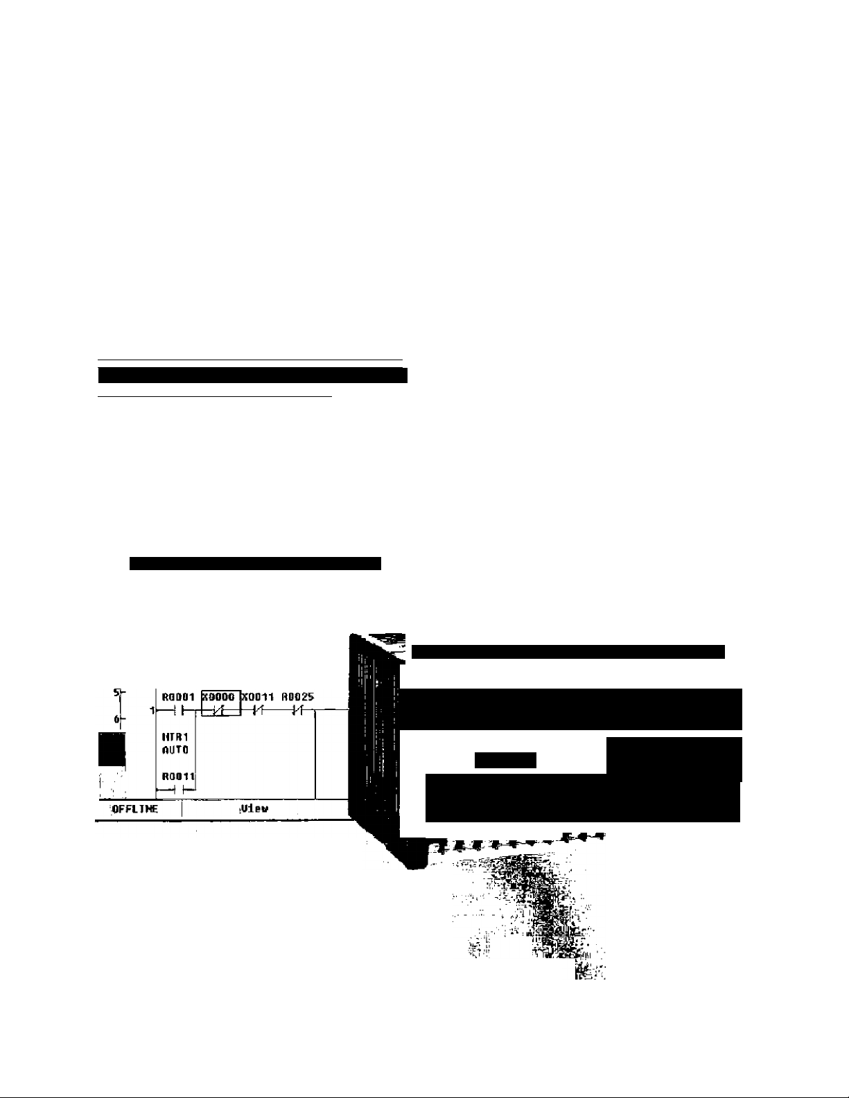
5 CCifT-SOF l■SA^ÍPLEI“ fámm Pr^irram Btoek 1 íim
Thls circuit controls notor 1- R001 is the rantact fron the nanual
2-
logic orto R011 is the contact Fron the auto logic.
MTR1 LOW MTR1 COW
MflNtI OIL FOIL OEHO
PRESS MODE
OPR
RESIT
I PrOr-'-rir r
i A^-—■—~ “T , Í
I ^iiaat n
T . 5 I i c ? t
TOSHrBA
' s? '. i-1 . « é e Í » »“'
f ^¡jB
------
- 1-,ftCj>EF^6i»3JS*? »•*
Advanced Features
• High-Speed Processing
• High Performance Software
-----
—— ’ . „ ^
I * ,^liS
_ _ Í- e '’ I----RjJWiS!'
• Unique I/O Option Cards
• Built-in Computer Interface and Active Serial Port
• ASCII Message Storage in Register & Program Memory
• MS Windows Programming Software
Page 2

PROSEC TI Series
Micro Programmable Controllers
T1 s are the micro programmable controllers in
Toshiba’s popular T-Series family. They are full-
fledged members of the T-Series family and all
programs written for a T1 will run on other T-Series
controllers. The T1s are palm-sized controllers with
CPU, I/O and power supply all in one small block.
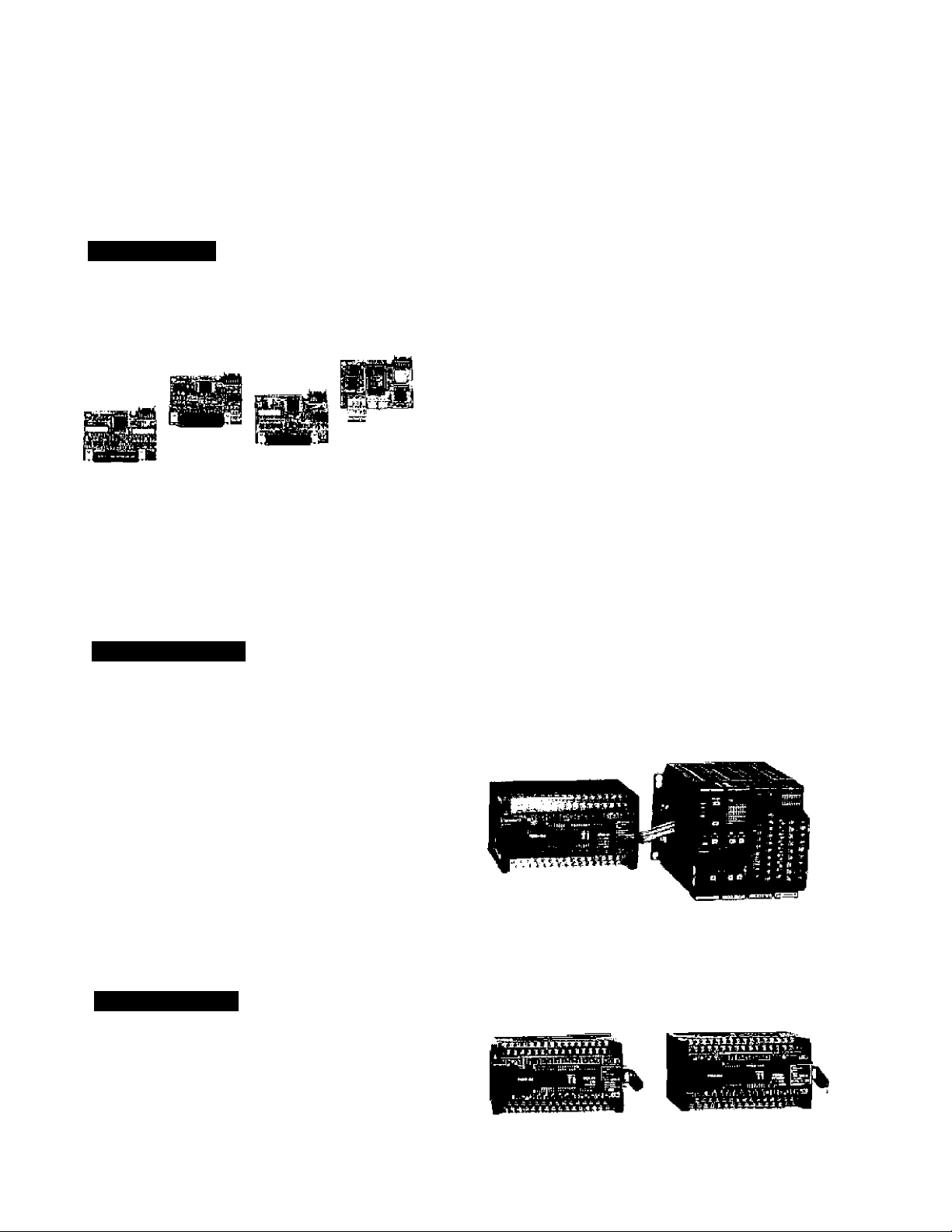
The TVs small size make it ideal for a variety of
applications including:
wiiili
"Si tF*"!
Tl
I
-T il jtt f*-, 1^ ^^1 rDJ».;. wv«
^ ".■i.- Ì:;- Ú ^ ‘i.
'i
f*lU- ,
■rin
, .
_
___
.ft.! . .
if-
• Packaging Machinery
• Punch Press Control
• Material Handling
• Washing & Drying Control
• Pneumatic Control
• Conveyer Control
• Compliance Monitoring
Many Others
'..ia '. »■■■■ HO :■ it
№
M£
Page 3
Flexible I/O
The T1 Series consist of four models, TI-16, TI-28, Tl-40 and T1-4QS. All four are block slyle
controllers allowing for I/O to be economicdly matched to specific requirements.
The TI-16 and TI-28 are fixed I/O non-expardable controllers. TheT1-40 and T1-40S I/O,
however, can be expanded. The I/O can be expandable three ways:
Option Cards
Toshiba used its advanced surface mount
technology to develop an extremely compact I/O
option card, Tbe I/O option cards are approximately
1/2 the size of a credit card, TheT1-40/T1-40S can
hold two I/O option cards inserted in the end of the
controller. The following option cards are currently
avalable.
• 16 points DC input
• 16 points DC output
• 8 DC in/8 DC out combo
• 1 channel Analog output
• 1 channel Analog output
• Field network TOSLINE-FIO remote
Expansion Rack
The T1-40/T1-40S can be connected to a two/four slot
expansion rack allowing it to Utilize most T2 Series I/O modules.
The following I/O modules are available for T1-40/T1-40S.
' 16 points DC input
' 32 points DC input
' 64 points DC input
' 16 points AC input
' 8 points relay output
' 4 channels analog input
' 1 channel pulse input
^ Communication interface
• 16 points DC output
• 32 points DC output
• 64 points DC output
• 12(>oinisACoutput
• 12 points relay output
• 2 channels analog output
• 1 axis position control
Expansion Unit
A block type expansion unit Is also available.
Each expansion unit has 32 I/O points (16 inputs and
16 outputs). The T1-40/T1-4DS can be connected to
either one expansion rack or one expansion unit
Page 4
T1 Series Line-up
TTi0 T1 Series consists of two CPU versions, T1 and T1S. The T1S is called the Super T1, it is an
enhanced version of the standard T1. Each version consists of different models, see following chart.
There are a total of 12 different types of T1 Series controllers.
T1 Series Line-up
Series
T1 Series'
Version
■T1
------
■T1S'
T1 vs. T1S Comparison
T1 2 k steps of program memory,
Standard functions
TIS
8 k steps of program memory (4 k mode or 8 k mode).
All the functions of the T1 plus buitt-in Ciock/calendar. built-in RS-485 communication port, on-line
programming function (4 k mode only), an-lirw EE PROM write function, expanded data memory,
and expanded instruction sat.
Mode!
T1-16
T1-28
T1-40
T1-40S
Type (Power supply & I/O)
T1-MDR16
T1-MAR16
(AC PS, DC In / Relay Out)
(AC PS, AC In / Relay Out)
T1-MDR16D (DC PS, DC In / Relay Out}
T1-MDR28 (AC PS, DC In / Relay Out)
T1-MAR28
T1-MDR28D
T1-MDR40
(AC PS, AC In / Relay Out)
(DC PS, DC In / Relay Out)
(AC PS, DC In/Relay Out)
T1-MAR40 (AC PS, AC In / Relay Out)
T1-MDR40D
T1-MDR40S
T1-MAR40S
(DC PS, DC In / Relay Out)
(AC PS, DC In / Relay Out)
(AC PS, AC In / Relay Out)
T1-MAR40SD (DC PS. DC In / Relay Out)
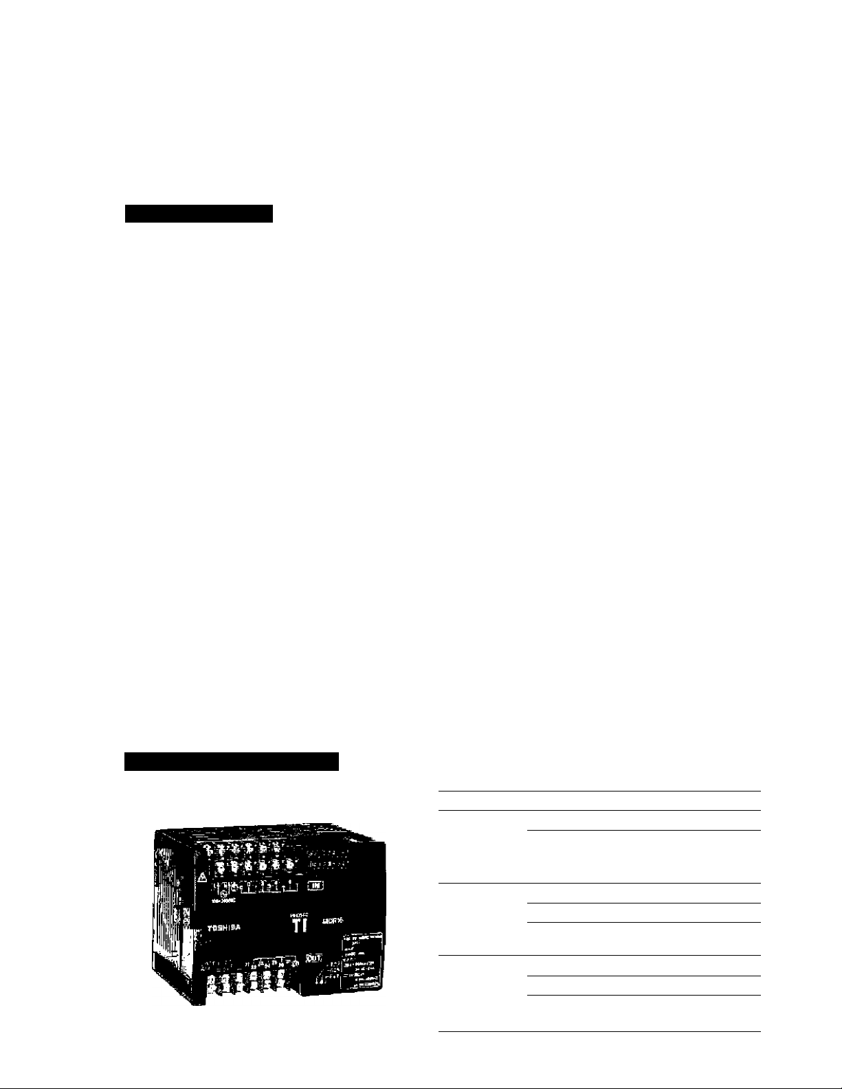
T1-16 (I/O non-expandabie)
Type
T1-MDR16 Power supply: 100— 240 Vac
(TDR116’6S)
T1-MAR16 Power supply: 100— 240 Vac
(TARlirSS) Input; 8 points, 100—120 Vac
T1-MDR16D
(TDR1ie*3S) Input: B points, 24 Vdc
Description
Input 8 pcints, dry contact
Oulpu; 6 points, relay and
2 points, transistor
Output 6 points, relay and
2 points, triac
Power supply; 24Vdc
Output 6 points, rday and
2 points, transistor
Page 5
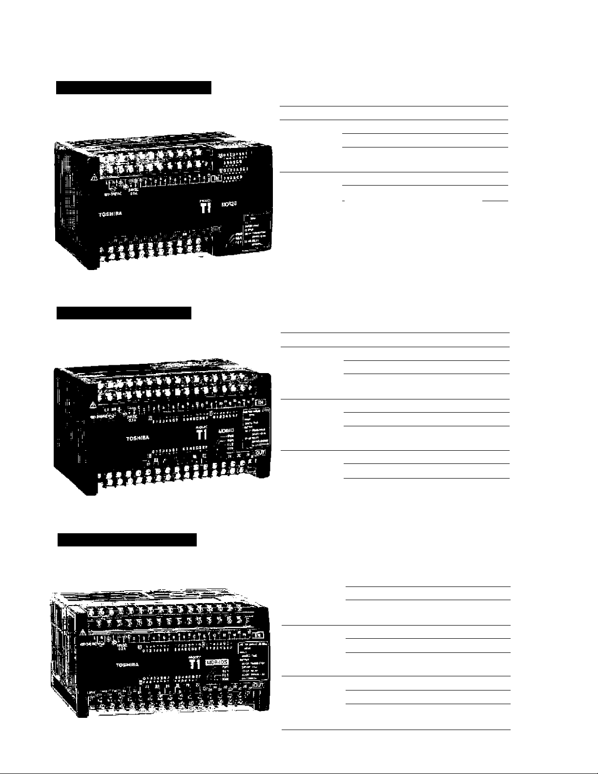
T1-28 (I/O non-expandab!e)
T1 -40 (I/O expandable)
Type Description
T1-MDR2S
fTDR12B*6S) Input: 14 points, 24 Vdc
T1-MAR26
(TAR128"6S) Input: 14 points. 100—120 Vac
T1 -M[>fll28D Power supply;
(TBR-iaS'SS) Input;
Type Descn'ption
T1-MDR40
frDH140*6S) Input: 24 points, 24 Vdc
T1-MAR40 Power supply; 100—240 Vac
(TAR140*6S) Input;
T1-MDR40D Power supply: 24 Vdc
(TDR14i)*3S)
Power supply; lOO— 240 Vac
Output; 12 pomts, relay and
2 points, transistor
Power supply; 100— 240 Vac
Output; 12 pants, relay and
2 points., triac
24Vdc
14 points, 24 Veto
Output; 12 points, relay and
2 points, transistor
Power suppiy:
Output;
Output: 14 points, relay and
Input 24 pDHits, 24 Vdc
Output; 14 points, relay and
10Q—240Vac
14 points, r^ay and
2 points, transistor
24 pomte, 100—120 Vac
2 points, triac
2 points, transistor
T1-40S (I/O expandable)
Tii» Description
T1-MDR405 Power supply; 100— 240 Vac
(TDR140S6S) Input;
Output;
T1-MAR40S Power supply: 100- 240 Vac
rTMi140S6Si Input;
Output: 14 points, relay and
T1-MDR40SO
rniRi40S;^) Input: 24 points, 24 Vdc
Power supply;
Output;
24 points, 24 Vdc
14 points, relay and
2 points, transistor
24 points, IDO—120 Vac
2 points, triac
24 Vdc
14 pointe, relay and
2 points, transistor
Page 6
T1/T1S Common Features
T-Series Compatible
The HP911A Handy Programmer and the T-PDS {T-Series Program Development System) software
program the entire family of T-Serles programmable controllers. Programs written for the T1/T1S are
upward compatible to other T-Series controllefs.
tl ' ' S 4 r I
.p - ^ I
^ f
■ 1!«
High-Performance Software
The Tl offers 17 basic ladder instructions and 76 insertable function instructions. The T1S offers 21
basic ladder instructions and 99 insertable function instructions.
Subroutines. Interrupt functions, Indirect addressing. Por/Next loops, increfnent/Oecremont. Pre
derivative real PID, etc. are standard on the T1/T1S, These fur>ctions allow the T1/T1S to be applied to
the most demanding control applications.
■* I
High-Speed Processing
Sophisticated machine control applications require high speed data manipulation. The T1/T1S is
designed to meet these requirements. High-speed data processing is the Tl/Tl S's key feature.
• 1,4 ps per Contact ■ 2.3 ps per Coil • 4.2 ps per Transfer
• 6.5 ps per Addition • B.8 ps per Multiplication • 5.0 ps per Comparison
The T1/T1S also supports the immediate interrupt function (DC input types only). This allows Inputs to
be recognized and outputs turned ON/OFF independent of the program scan.
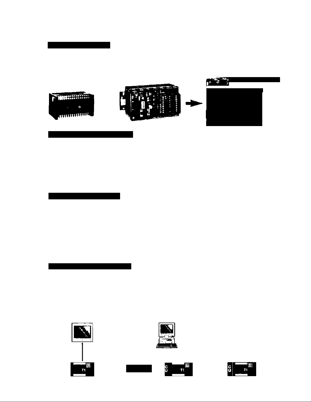
Built-in Computer Interface
The Tl /T1 S’s RS-232C programmer port can accept computer read/write commands. This results in
easy connection to higher level computers, operator interface units, etc. By using the multi-drop
adapter {CU111). up to 32 T1/T1SS can be connected to a master computer. The TI/TIS has the same
communications protocol as other members in the T-Series family.
Operator Interface
Master Computer
Remote programmlngfmonitoring via
modem (radio/phone) is possible.
(Ver 1.20 or later tor standard Tl ’s)
RS-232C
RS-485 (1 km max.)
1 Max. 32T1s
U Tl"
Page 7

ASCII Message Storage in Register & Program Memory
T1/T1S can store ASCI) messages in either program memory, register memory, or both. There are over
1,000 data registers on the standard T1 and over 4,000 data registers on the TIS that can be used tor
ASCII message storage. This makes T1 s ideal for use with the low-cost operator interface stations that
require massages to be stored in the PLC.
High-Speed Counter Input
The T1/T1S has twro high-speed counter inputs {DC input types only). These 5 kHz counters can be
used independently {of each other and of CPU scan) for discrete parts count in applications requiring
high-speed compare, reset, and strobe. The counters can also be used together as a quadrature
counter.
Pulse Encoder
Phase A
Phase B
5 kHz max, for each phase
tjT «W|
Both risirrg and failing edge of each phase are counted.
20 k counts per second max.
Analog Register Adjustment
Each T1/T1S has two terminals {which can be adjusted with a screwdriver) that vary the value In two
separate registers. These registers can be used as presete for timers and counters, maximum,
rninimum, or equal values for comparisons, add or subtract adjustments, etc.
Pulse^PWM Output
An output from theT1/T1S can generatea variable frequency output {5 kHz max.). The output can also
be driven so that h switches ON and OFF at varying duty cycles. This output can ba used to drive a
stepper motor or to simulate an analog output (DC input types only).
Stepper Motor Driver
CW Pulse
CCW Pulse
_nnn_
Stepper Motor
Output pulse rate; 50 Hz to 5 kHz
Password Protection
The T1/T1S can ba programmed with no password, or with one of three selectable protection levels.
This is a serious password utility. There is no way for anyone to recover, modify or view a fully
protected program.
Page 8

T1S Features
Large Program Memory
Ttred of loading a micro PLC with different programs or different recipes for each different part or
different process? The T1S has 8 k steps of program memory & 4 k words of data memory.
Several programs and recipes can be easily loaded into a TIS. Then, simply select the program or
recipe to be executed.
On-line Program Changes
In the 4 k memory mode, It is possible to make program changes and write to the internai EEPROM
while the T1S is executing the user application program. This feature is very important in process
control applications where it is not always possible to stop the process just to add an additional
interlock or permissive.
Real-time Clock/Calendar
The T1S has a real-time clock/calendar for year, month, day, day of the week, hour, minute, and
second. It can be used for performing scheduled operations {each Sunday at 6 pm), time and date
stamping event occurrences, etc. The real-time clock/calendar is backed up by built-in capacitor.
The back-up period is more than 7 days (25’C).
Built-in RS-485 Communication Port
TheTIS has a built-in RS-485 multi-purpose communication port. This port can operate in one of
three (3) different modes.
Computer link mode
T-series computer link protocol can be used in this mode, A maximum of 32 TiSs can be connected
to a master computer, operator interface station, or other higher level controller. In this mode, the
computer can read and write to all the registers in theTfS. The T-series PLC programming software
(T-PDS) can also be used In this configuration to program each of the Ti S’s.
M^ter Computer
m
RS-465 (1 km max,}
■
Max, 32T1SS
Page 9

Built-in RS-485 Communication Port (cont’d)
Free ASCII mode
In this mode, user defined ASCII messages can be transmitted and received, A terminal, printer, bar
code reader, or other serial ASCII device can be directly connected to the T1S, This mode allows the
T1S to communicate with other PLCs (T1, T2E, T2N, etc.), Inverters (VF-S7/A5, G3), motor protection
relays (S2E21), and other devices with a simple ASCII read/write protocol.
T1S
RS-485 2-wire system is also possible.
RS-485 (1 km max.)
Bar-code reader
Printer, etc.
T1
T1
Inverter VF-S7
Motor Protection Relay
S2E21
Data link mode
In this mode, two (2) PLCs (any combination of T1S, T2E orT2N) can be directly linked together. This
direct link is inexpensive, easily configured and require no special programming. Data registers DOOOO
to 00031 are used for the data transfer.
T1S
RS-485 (1 km max.)
Station No.t
DOOOO
T1S
Station No.2
DOOOO
*
D0015
DQ016
D0031
D0016
D0016
D0031
Page 10

I/O Expansion
Option Cards
These option cards are extremely compact I/O expansion cards. They are approximatejy 1/2 the size of
a credit card. The T1-40/T1-40Scan hold two option cards inserted in thewid of the controller. By
using the option cards, the T1-40/T1-40S can expand its I/O without increasing panel mounting space.
The following eight types of option cards are available.
Type Description
DI116
D0116
DD116
ADI 21
AD131
DAI 21
DA131
FR112
Note: Cable side corn^ector ti not Irdudad witti Ihe Dl, CO, or DO oanJ,
16 points, 24 Vdc Input, 5 mA {ktotal
16 points, 24 Vdc output, 100 mA iNoiai
0 points, 24 Vctc input, 5 mA
B points, 24 Vdc outpul, 100 mA iMotai
1 channel analog input, 0 to 5 V/0 to 20 mA,
12-bit resolution. Internal-exIsrrral isolation
1 channel analog input, -10 to 10 V,
12-tHt resolution, Intemal-extema! Isolation
1 channel analog output, Q to 20 mA,
12-bit resolution, Internal-external isolation
1 channel analog output, -10 to 10 V,
12-bit resolution, internal-external isolation
TOSLINE-F1D remote Statical,
1 word input + 1 word output
l( tieparstel^ available. (PT15S or Pri№)
Using Analog I/O Cards:
The TI -4Q/T1-40S's PID function and analog I/O option cards enable the Tl-40/ri -40S to be applied
to process control applications.
T1-40/T1-4ÜS
{w/ AD card
and DA card)
PID operation
Using the TOSUNE-F10 Remote Station;
Ttie TOSLlNE-FiO Is a high-speed field level network. In a TOSLINE-FIO network, the
T1-40/T1-40S work as an intelligent remote stations.
T2E (master)
11^
MV
PV
TOSLINE-f 10 (twisted-pair)
Sensor
Nôlb: Wtieb VF-A513 conriected, at teOirt «1« Ramota Input block
wllh a lower etalion addrest rouìl connected.
Closed Loop Control
Process
■Temperature
• Flow
• Pressure, etc.
|Hg ^ IM
T1-40
(W/ FR112)
T1-40S
(W/FR112)
T2E
(remote)
Remote I/O Remota I/O
a
Inverter VF-A5
10
Page 11

Expansion Racks (for mounting T2 1/0 modules)
A 2 or 4 slot expansion rack can be connected to the T1-40/T1-40S. By connecting the expansion rack.
T2 series I/O modules can be used with the T1-40/T1-40S. Interna] 5 Vdc power is supplied irom the
T1-40/T1-40S.
Type
BU152
BU154
Description
Z modules, with 0.15 m cable
4 modules, with 0.15 m саЫа
Available T2 series I/O modules:
Type
DI31
□132
□1235
IN51
IN61
R061 Relay output
R062
D031
D032
D0235
DO^P
A061 Triac output
AI21
AI31
AI22
AI32
A031 Analog output
A022
À032
PI21
MC11
C^11 Com municalion l/F 1 port of RS-252C, free ASCII torrhat, 300 to 19200 bps, 32Q bytes (max.)
Marne
DC input
AC mput
Transistor output
Analog Input
Pul^ Input
Position control
Specifications
16 points, 12—24 VdCi'ac input, 3 mA
32 poirte, 24 Vdc input, 5 mA (connector type)
64 points, 24 Vdc input, 4 mA (connector type)
16 points. 100—120 Vac input, 7 mA
16 points, 200—^240 Vac input, 6 mA
12 points. 240 Vac/24 Vdc output, 2 A/poInt (max.)
8 points (isolated), 240 Vac/24 Vdc output, 2 A/point (max.)
16 points, S—24 Vdc output (current sink). 1 A/point (max.)
32 points. 5—24 Vdc output (current sink). 0,1 A/ptxnl (max.)
64 points, 5—24 Vdc output (Current sink), 0.1 A/poInt (max.)
16 points, 24 Vdc output (current scurce), 1 A/point (max.)
12 pointe, 100—240 Vac output, 0.5 A/point (max.)
4 channels, 4 to 20 mA/1 to 5 V input, 8-bit resolution
4 channels, 0 to 10 V input. 8-bit resolution
4 chatnels, 4 to 20 mA/1 to 5 V input, 12-bit resolution
4 chann^s, -10 to 10 V input, 12-bit resolution
2 channels, 4 to 20 mA/1 to 5 V/D to 10 V output, 8:bil resolution
2 channels, 4 to 20 mA/1 to 5 V output, 12-bit resolution
2 channels. -10 to 10 V output, 12-blt resolution
1 channel plus input, 5/12 V, 100 kpps (max.)
—
Expansion Units
A 32 point expansion unit can be connected to the Tl -40/T1-40S. A 0,5 tn cable is included with the
expansion unit. Internal 5 Vdc power Is supplied from the T1-40/T1-40S, 24 Vdc power for the output
relay coils is required from an external source (such as tfie controller).
Type
T1-EDR32
T1-EAR32
Description
16 points. 24 Vdc Input, 7 mA
16 points, relay output, 2 A/point (max.)
16 points, 100—120 Vac input, 7 mA
16 points, relay output, 2 A/point (max.)
11
Page 12

Programming Tools
T-Series Program Development System (T-PDS)
The T-Series Prcjgram Developmeni System (T-PDS) is a software program that runs on any Toshiba’s
Notebook computer or other IBM-PC compatible peraonat computer. The T-PDS software supports
on-iine/off-line programming, debugging and program documentation for all T-Series programmable
controllers: T1 m S, T2/r2E/T2N and Ta/T3H.
The T-PDS software has:
• A full-feature program edit that includes cut & paste,
search & replace, insert, delete, etc.
• Group programming and block merge.
• On-line programming & EEPROM write. (TIS)
• Load, save and compare programs between disk file and CPU
• Monitor power-flow status of on-line ladder program
and display of register values.
• Sampling trace screen for checking ©vent time sequences,
• Disable inputs and force coils ON or OFF from keyboard.
• Document programs with commentary,
• Print map options such as register values, register/device
usage, full cross-reference, etc.
• Built-in Modem initialize and Dial-up.
12
htDie:
For the TIS, Itie T-PDS visions are required.
• T-POS (WifHlowiaJ V» 1,2 or later
* T-POS (MS-DOSi,- Ver2.1 or later
Page 13

Kandy Programmer (HP911A)
Tile HP911A is a hard-held graphic programmer. Its
portability makes it ideal for maintenance use at remote
locations. The HP911A has all the features of a full size
programming terminaJ. (2 m cable for T1 is included)
• Ladder logic programming of T-Series programmable
controllers T1/T1S, T2/T2E/T2N and T3.
• Suilt-in EEPROM allows program copy between
T-Series controllers.
• Two display modes,
- Normal: S lines and 12 columns
- Zoom: Full device description
• Data monitor for I/O and internal registers.
• On-line programming & EEPROM write. (T1S)
Net«:
SameTl & r jtictlons are limited wild usmg ttie HPiii lA,
• On-line data set & I/O force.
• Backlit LCD display for better operation In dim light.
Program Storage Module (RM102)
Multi-drop Adapter (CU111)
The RM102 is an external memory device, which can
store a T1/T1S program. By using the RM102, program
transfer from a master T1/T1S can be easily done without
the need for a computer or hand held programmer. Two-
button operation makes program loading/saving
accessible to anyone. However, if a password is used in
the T1/riS, the password in the RM102 must match
before a program load is executed.
The GU111 is an RS-232C/RS-485 converter dedicated
to then Series, By using theCUm, up to 32 T1/T1Ss
can be connected to a master computw or higher level
controller via an RS-485 link, The master computer can
run a SCADA, MM! or DDE Server program. The T-PDS
programming software can also be used through the RS-
485 link to program or monitor each individual T1/T1S,
(T1 version 1.20 or later is required for connecting the
T-PDS programming software)
13
Page 14

Instruction Set
Basic Instructions
FUN
S^bol Name
NO coritact
VI-
m-
1 h
“t M
•( H
III
KiH
If^h
-(PM
-(N>1
MCS Masler control set
MCR
JCS Jump control set
JCR
TON ON delay timer
TOF OFF delay liner
SS SIngle-sIwt timer
CNT
END End
NC contact
TransiKonai contact
[rising edge)
Tran^ionaJ contact
¡fatlifig edge}
Coi!
Forced coil [debugging
purpose only)
Inverter
Invert wil
Po&fltve pulse contact
Negative pulse contact
Positive pulse co<l
Negative pulse coil
Master control reset
Jump control reset
Counter
Available
T1 T1S
v' V
V
V
yi V
V
V </
V
V V
V
V
Function Instructions
FUN
Symbol Name
Nd.
13
MOV Data transfer
19 DIvfOV
V
v'
V
l/
V
v'
</
20
NOT
22
XCHO
24 TINZ Table initialize V
25
TMOV Table block transfer
26 TNOT Table invert tr^sfer
27
28 - Subtraction
29 Multipl [cation
30 / Division
31
D4 Double-word addition
32 D- Double-word subtraction
35
+c
36
-C
39
u*
40
u/ Ur^igned division
41 DIV
43 +1 ifKiBment
45 -1 Decrement
48 AND AND y
50
Oft OR vf y
52 EOR Exclusive OR
56 MAVE Moving average
61 DFL
HTOA HEX to ASCII conversion
62
63 ATOM ASCII to HEX conversion
64 TEST
68 SHF11 1 bit shift right
69
I SHL1
70
SHRn
71
SHLn n bits stuff left
74
SR
75 DSR
RTR1 1 bit rotate right
78
RTL1
79
RTRn
80
~RTLn n bits rotate left
81
MPX
90
DPX Demultiplexer
91
Double-word data
trartsler
Invert transfer
EKchange
Addition
Addition wflDi can7
Subtraction with carry
Unsigned nriuHIplicadon
Urtsigned
douMe/single division
Digital filter
Bit test
1 bit shift left
n bits atiift right
Shift register
Bt-directional ^rift register
t bit rotate left
n bits rotate right
Mult^fexer
Avalflble
T1
TIS
V'
V
V
/ V
V
V V
V V
V
V
V y
vf
V
V y
v'
V
V
V
V
V y
v'
r/
v'
V
V
1
V y
V
V y
V
V
V
v'
V
V
V
V
/
y
y
y
y
y
y
y
y
y
y
y
y
y
y
y
y
y
y
y
14
Page 15

RJN
Symbol
No. T1 T1S
96
>
97
>=
98 &
99
<> №1 equal
Manw
Greater than
Greater than or equal
Eejüaü
10Ö < Less than
<-
101
102
D>
103
D>=
104
0=
105
0^>
106
D<
107
D< =
108
U>
109
U>=
110
u=
111
u<>
112
u< Unsigned less than
113
u<=
114
SET Devtce/regislei set
115
RST
lie
SETC
Less than or equal
Doubte-word
greater than
Double-word
greater th^ or equal
Ooi£>le-word equal
Doiri)le-word not equaJ
Gouble-word less than
Double-word less than
or equal
Unstsned greater than
Unsigned greater than
or equal
Unsigned equal
Unsigned not equal
Unsigned less than
or equal
Device/regüst» reset
Set carry
Available
V
V
V
V»
V
V V
V
vf
y
119 flSTC Reset carry
120
ENC
121
DEC
122
BC
128
CALL
129
RET
132
FOT
133
NEXT
137
SUBR Subrouine ^try
140
El
141
Dl
142
IRET
143 WDT
144
snz
145
ST1N Step sequence input
Encode
Decode
Sit count
Subroutine call
Subroutine return
FOT-NEXT loop (FOR)
FOR-MEXT loop ¡Nen>
Enable irtemipt
Disable intern^
Interrupt return
Watchdog timer reset
Step sequence
bit^izalion
V V
V
V V
V y/
V
V
FUH
Symbol Name
Na
146
V
V
149 U/D
V
V
STOT
147 F/F Fiip flop
154
CLND
155 CLDS
156 PID3
V
160 OL
161 LL Lower limil
162 MAX
163
V
y
yf
164 AVE Average value
165 FG
180 A6S
y/
V
y/
yf
yl
yl
235 1«
V
MIN Minimum value
182 NEG Two’s complement
183 DNEG
185 7SE6
185 ASC
18B SIN Binary conversioti y/ y!
190 BCD
XFER
236
237
READ Special module data read
238 ¡WRITE
Step saquenoe output 7 V
Up / down counter
Calendar set
Calendar operation
Pra-derivative real PIO
Upper lirhlt v'
Maximum value
Function gerrerator
Absolute value
Doiible-vrord two's
oomptemant
7-segrrwnt decode V
ASCII conversion
BCD oorwersion
Direct Input/output yj yi
Expanded data transfer
fecial module data write
Available
T1 T1S
7
f
V V
V
v' y!
y/
V
y/
yi
yf yi
V
V
V
7
V
v'
y'
V
v*'
y!
V
y/
yi
yi
y}
yi
V
V
yi
yf
V
/
yf
yf
yf
yi
y/
V
15
Page 16

Specifications
Functional Specifications
Model
Control (TVBOxxj
Scan system
I/O update
Pro^wn memory
RAM memory back-up
Program capacity
Pra^amting language
Instmcti'ors
Execution speed
Program types
I/O capacity
Input
^jBciicatkjn
Output
specIficatiDn
I/O temninai block
User data Auxiliary relay
Fteel-time clock/calendae' No
Special I/O functions
Communications interface
Debug support function
DC irput type
AC input typo
DC input type
AC input type
Special relay 1024 pomts/Ç4 words (5/5W)
Timer
Counter
Data register 1024 words (D)
Index register
T1-16
Stored program, cyclic seen system
Roatirg scar or constant scan (10—200 ms, 10 ms units)
Batctii I/O refresh (direct I/O Irtstruciion avallabis)
RAM (capacitor back-up) and EEPROM (no back-up baftery required)
6 hours (2SO)
T1-28 T1-40
2 к steps
Ladder diagram with function block
Basic ladder instructions: 17
Fungiksn block instiucBons; 76
1.4 ps/<wntact, 2,3 |js/go«I, 4.2 ps/16-bit transfer. 6.5 (ia/16-blt addition
1 main program
Î subprogram (initial pro^m)
1 lime interrupt (interval; 5 to 1 (»0 ms, 5 ms units)
4 I/O interrupt (hi^-speed counter and interrupt input)
16 subf outirws {nesting not available)
1 e points
(8 iiV8 out)
Dry contact (AG PS)
24 Vdc, 7mA (DC PS)
(curren! sink or
source)
100-120 Vac.7mA
Relay: 240 Vac/24 Vdc, max. 2 A/poini
Transistor (2 pointa): 24 Vdc, max, O.S A/point
Relay: 240 Vac/24 Vdc, max. 2 A/(X3ini
Triac [2 poinls): 100—240 Vac. max. 1 A/poInt
Fixed
1024 points/64 words (R/RW)
B4 points (T./T), 32 Щ 0.01 s, 32 @ 0.1 3
64 poirrts {CVC)
3 words (1, J, K)
High sprod counler (2 single or 1 quadrature) or Interrupt input (2 points),
Adjustable analog register (2 points).
Pulse output (CW+CCw or pulse+deecticn) or PWM output
1 port of RS-232C(programrrKr port)...Programmer or Ckjmpular Imk
Sampling trace {a devices - 255 times or 1 register - 128 times)
28 points
(14in/14out)
24 Vdc, 7 mA (cixrefirt sink or source]
Dry contact input Is ^so ai'Silable by using 24 Vdc service power
Removable
“ 1
T1-40S
16B hours {2ffC)
8 к steps
(4 к or 8 к mode)
Basic: 21
Function : 9S
256 subroutine
(up to 3 nesting)
40 points (24 in/1€out),
expandable up to 328 points
4066 points /
256 words (FVRW)
256 рР1П|5(Г,Л)
64 e 0.01 5,
192® 0.1 s
256 points (C7C)
4098 words P
Yes, (i30 s/month)
1 portotRS-4S5
—
TOSLINE-FtO Termite {by орИоп card)
—
-Programmer,
-Computet link.
-Data, link,
-Free ASCII
Sampling trace
(6 device and
3 reglsler - 2S6 times}
On-line progrannilng
On-line EEPROM
— write
16
Page 17

General Specifications
Model
Power Emjpty vottage
Power consumption
Hetenlive power mtemiption
Withstand voBagg
Ambierl temperattfo
Ambient bmnldity
Noise immurrfty
Vibration immunity
Shock immunity
Standard
External Dimensions
T1-16 T1-28 T1-40
-100 to 240 Vac (-»-10%. -15%>, 5(VSDhtz / 24 Vdc(t-2D%, -15%}
30VAortess(AC)M2Worless (DCj aaVAar less(AQ/
10 ms or less
1500 Vac—1 minute (between power lenrtiruiis and ground terminal)
0 to 55 °C {operation), -20 to 75 "C fetorage)
20 to 0D% RH, no condensation
1000V p-^1^ us,_3Si'536/EeC {EMC directive) _
1Ó.7 Hz—5 mm p-p (5 mutually perpendicular axis)
gs m/s' (Id g), (3 shacks per axis, on 3 nnuluafiy perpendicular axis}
UL/c^UL, CE
........................................................................
lÖWortess(DC)
T1-40S
45 VA or less (AC)/
18 W or less (DC)
TM6
IIS
jMI
Expansion Rack
BU152
rr
BU154
74.S
T1-2S/T1-40/T1-40S, Expansion Unit
2^
!lil:
n
LI
>:c öWKEKt! Í Q OCIiawni
158.S
167.6
Terminal bloch type
I/O used
'’ll!
l¡ir'
1
&J.»
Connector type
I/O used
_ - TiS
-
.Ü
j
'
J
Connector for Option Card
Ootkm card
Dll lerDQlieiTID116 tia
A0121 /AÖ131 /DA121 mA'l31 Í6
mii2 1Í
Program Storage Module / Multidrop Adapter
X.
s
o
D
15'
A
Unit; lem
17
Page 18

Ordering Information
Item Dsscriptian Typo cods Pari number
T1-16
T1-3B
T1-40
T1-40S
Option
card
AC PS
DC PS DC input T1-MDR16D TOR116*35
AC PS
DC PS OC input Ti-WDR26D
AC PS
DC PS
AC PS
DC PS
16 pts DC Input DM IS TDI116‘BS
16 ¡its tX: oulpul
811/8 out combo
OC input T1-lutDP16 TDR116'6S
AC input
DC input
AC input TVMAR28 TAfi12e'6S
OC input
AC Input
DC input T1-MDRI0D
tX input TVMDR40S TDR140S6S
AC input
DC input T1-MDR40SD
T1-MARIE TAR116'6S
T1-MDR2S
T1-MDR40
T1-MAR4D
TI-tAARAOS TrWUDSeS
D0116
DD11S 100116*55
TDR12B’BS
TDRi2r3S
T0R14CT6S
TAR140-6S
TDR14D‘3S
TDR140S3S
TD0116‘BS
Item □eschpUan Type coda Part number
T2I/0
module
I6pls24 Vdo input
32 pla 24 V(fc mput
64 pis 24 Vdc iiput Dt235 TD1255“S
16pls12CIVau input
16 pis 240 Vac inputIN61 EX10‘MIH61
12 pis relay oegxrt RÛ61 EXIO-MROSt
S pt6 r^y output
16pi3 24Vdc
output
32pts24 Vdc
output
64 pis 24 Vdc
output
1S pis 24 Vdc
output ixjiKni icuiiO
ÛI31
DI32
IN51
R062 eXIO'MROK
DÛ31 EX10-MDO31
D032 Exio'MDoaa
D023S TDOS35'*S
D0213P TD0533P*S
EXKTMDiSI
Bt10‘'MDI32
EXIO'MINBI
1 c4 analog infiot,
0-5 V/0-20 mA
1 c1i analog input,
tIOV
1 $h analog output,
Q—20 mA
1 ch analog output,
tIOV
TOSUNE-FIOmmote
Expsn^cn
rack
AD121 TADi21'BS
A0131 TADISI'BS
DA121 TDA121‘BS
OA131 TDAiarBS
FR110
TFR112'B8
BU152 TBU152“S
4slots|w/a.'t5tiiciMgfBU154 TBtJ154“S
Expansion
unit
Peripheral T-POS (MS-DOS) T-PDS TMM33I155
CO Inpot V^e
AC input type
T'PDS (Windows)
Handy programmer
T1-EDR32 TDRISaE-S
T1-eAR32
T-PDSWin TMW33E1SS
НРЭ11А
TAP132E-S
THP911A*S
Cable and
others
12 pts too—240 V«:
output
4 ch Analog8-bit AI21 BC10"MAi21
in pul
2 ch Analog
output
1 ch pula a input P12l EX10‘MP121
Position control
Cofrirunication 1/F CF211 TCF2ir*S
T-POS cable (5 mj CJ105 TCJIOS'CS
BS-232C connector
Opfor card conoectof
AC61 EXIO'MAOet
AJ31 EXtO‘MAI3i
12-bit m2 eX10'MA122
m2 EX10‘MAI32
AÛ31 EXIC'MAOai
3-bil
12-bit A022 EX1C‘MA022
A032 EXIO'MAOK
MC11 EKIC'MMCH
PT16S TPTies'AS
PT15S TPT15S‘AS
18
Prog ram sic rags
fmodula
Multi-dFOp Briaptw
RM102 TRMioa*'S
cum
TCU111"S
Option »6 oomeckr
№IC№l»typ*i
Empty slot cower
lIcfcrparEibn rnd^
PT15F TPT15F‘AS
—
EXIO'ASn
Page 19

Quality
Qiiality is a religion at Toshiba. Quality starts at the very basic level, the 1C (integrated circuit), and
proceeds though design development, assembly, and testing of many different consumer
and industrial products.
Toshiba corporation’s quality management system In
d^ign, development and manufacturing of
programnnable controllers Is approved to satisfy the
quality management standard ISO9001.
19
Page 20

Safety Precaution
A
Thit product telriWitdeil to bo used tor the control ef indUMr^l
machines end prooMaea,
Misuse of Utie product can rosuli In propartjp damage or human muty.
^csd lelDted mofiuada enrefully bafpto using this product.
PROSec and TOSUME Bre ragisterad trsdamerk» ol TOSHIBA Corporation,
I8W1 is a registered tradeirtafi; ol Inlamattoral SusinesB Machines CraporaMn.
MS-DC^ pod VUindc'/ra are registered tmdeniartis ol Moropplt Cctpcretiart.
ForfLsther mtormallon, please ccniact yournsErest ToBhlba Roproaentatlvo or
Internstlortal Operatlona-PiDdLcer Goods.
The date given in tMs brochure are subioet to change without notice.
In Touch with Tomorrow
TOSHIBA
TOSHIBA CORRORATIOM
Indusirial Equipment Depanment
M.ShIbaura 1-dhctne. vtireto-ku,
Tokyo 105-3001, Japar
Tol.i (0313457-Jl900 Fax,' (0315444-9263
9S-2(KS16526
Toshiba Inlamelionat
Cerperatipr
Indusidai Din'slpn
ttouslon USA,
Tel,; 713-466-007?
Fas.: 713-463-8773
Toshiba Inlernatrarutl
CortMcallcn (Europe) Ltd.
Miditser u.K.
Tel,;018l-;S6-6t>03
Fax.: Diai-f}4a-4gee
ToeMba lnterngt>pn»i
Corporatinn Ry., Ltd,
Sydney Australo
T«i,;CK-9?es-e6flG
Fax.; Q2-9BKF7542
Toshlta Asia PaciOc
Pt*..Ud.
SiTigspore
Tel : 324-ItMS
Fffi.; 324-5286
Bangid* Office iThiii aid)
Tei,;Q2-a3fi-a4iiimoa
Fax.; 02-337-4682
TpsiHbado
SreaS, SA.
SiaiPwio SiasI
Tel,; 011-76^7199
Fax,; On-76^-71^
Prinled In Japan
 Loading...