

Toshiba T1950, T1950CS, T1950CT User Manual
1-1
1.1 Features
The T1950, T1950CS and T1950CT units consist of the following features.
Processor Intel SL-Enhanced 486DX2/40Mhz. (P24S chip)
Processor Type DX2: (3.3v w/8KB internal cache) Co-processor embedded.
BIOS 128KB flash EPROM (150ns)
RAM 4MB Expandable to 20MB (80ns)
Display T1950: Fluorescent Sidelit Monochrome LCD
T1950CS: Dynamic-STN Dual Scan Color LCD
T1950CT: TFT Active Matrix Color LCD
Ext. Display T1950 & T1950CS: VGA 640 x 480 (16 colors of 4096)
T1950CT: 800 x 600/256 colors;1024 x 768/256 colors
(using Toshiba supplied drivers)
FDD 3 1/2" 1.44MB
HDD T1950 & T1950CS: 120MB/200MB
T1950CT: 200MB/320MB
Optional Peripherals 101-key Keyboard (PS/2)
1 - 14.5mm PCMCIA Type III (2.0)
Ports 1 9-PIN Serial (16450 UART)
1 Parallel/FDD: BI-DIR
1 15-PIN RGB
1 Mouse Quick Port (DCBM)
1 PS/2 Mouse Port (not usable if DCBM connected)
Keyboard 1 101-key Keyboard Port (PS/2)
82-Keys, 3mm Travel
Battery NIMH (12V 2400mAH) PART# PA2420UXRA
Battery Life 2-3 HRS.
Recharge Time 1.4-2.3 HRS (Computer off only)
AC Adapter T1950 & T1950CS: Input: 100-240VAC , Input Frequency:
50-60Hz, Input Power: .5A - .28A (50/60Hz)
Output Voltage: 18 VDC, 1.1A
T1950CT: Input: 100-240VAC, Input Frequency: 50-60Hz,
Input Power: .7A - .4A (50/60Hz)
Output Voltage: 18 VDC, 1.7 A
Bundled Software Toshiba DOS 6.0; Windows 3.1; MaxTime; Ultrafont.
Dimensions T1950: 11.7"W x 8.4"D x 2.0"H, 6.4 lbs.
T1950CS & T1950CT: 11.7"W x 8.4"D x 2.1"H, 7 lbs.
1-2
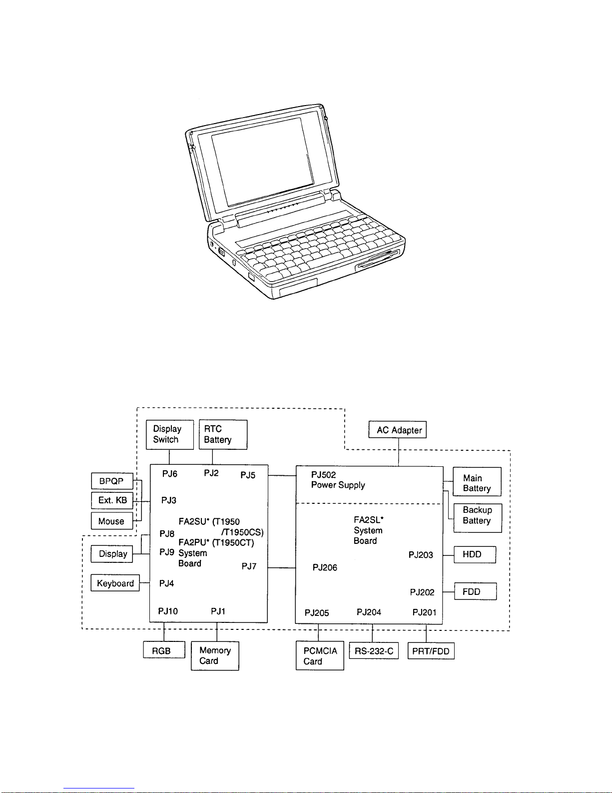
The T1950 Series Personal Computer is shown in Figure 1-1, and its system configuration is
shown in Figure 1-2.
Figure 1-1 T1950 Series Personal Computer
Figure 1-2 T1950 Series System Unit Configuration
1-3
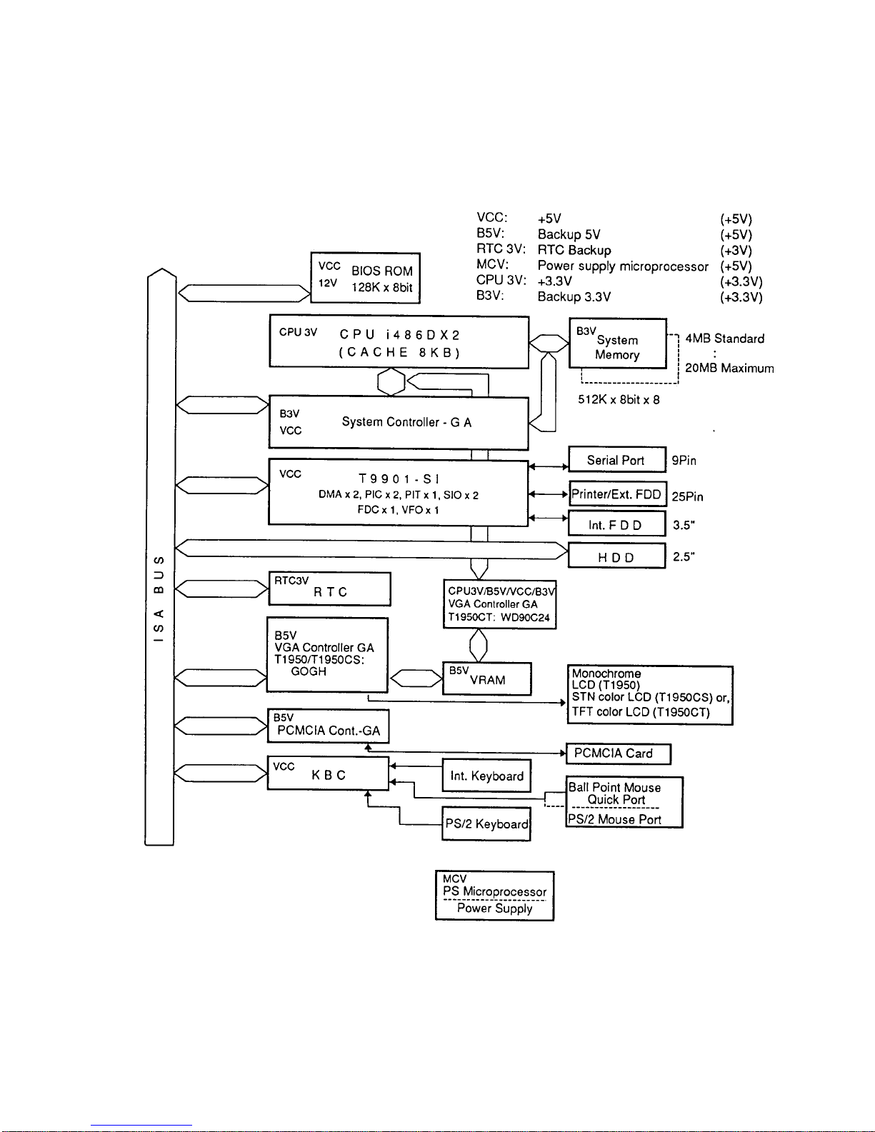
1.2 System Unit Block Diagram
Figure 1-3 is a block diagram of the T1950 Series system unit.
Figure 1-3 T1950 Series System Board Block Diagram

1-4
The T1950 Series system board is composed of the following major components:
❑ An i486DX2-40 CPU
❑ Super Integration (SI) T9901, which stores the following components:
• Two Direct Memory Access Controllers (DMAC): 82C37
• Two Programmable Interrupt Controllers (PIC): 82C59
• One Programmable Interval Timer (PIT): 82C54
• One Floppy Disk Controller (FDC): TC8565
• One Serial Input/Output Controller (SIO): TC8570
• One Variable Frequency Oscillator (VFO): TC8568
• One I/O Controller
• One Printer Port Controller
• One Speaker Controller
❑ A Real Time Clock (RTC)
One T9934 chip is used. The T9934 has 128 of bytes memory. Fourteen bytes of
memory are used for the calendar and clock. The remaining 114 bytes are used for the
system configuration data.
OSC (X3) generates 32.768 KHz for RTC.
❑ A Keyboard Controller (KBC)
One M37452M4 chip is used.
This KBC includes the keyboard scan controller and keyboard interface controller.
The KBC controls the internal keyboard, external keyboard port, PS/2 mouse port,
and Ball Point Quick Port.
❑ The following memories:
Standard RAM: 4 MB
Cache memory: 8 KB (inside CPU)
BIOS ROM: 128 KB (96 KB are used)
This ROM contains Initial Reliability Test (IRT), Basic Input/
Output System (BIOS), and video BIOS.
Video RAM: 256 KB
Optional memory cards expand memory to a maximum of 20 MB.
❑ VGA display controller
T1950/T1950CS (GOGH): This controller controls internal and external VGA compatible display.
T1950CT (WD90C24): This controller controls internal VGA display and external
SVGA compatible display.

1-5
❑ Clock Generator receives 14.31818 MHz (X2) and generates the following frequen-
cies:
• 20 MHz for the CPU (CPU operates at 40MHz.)
• 14.7456 MHz for the COM
• 24 MHz for the FDC and VFO
• 16 MHz is used for GA
• 14.31818 MHz is used for T9901 (SI)
❑ Gate Array
System Controller Gate Array
This gate array has the following functions:
• CPU Controller
• Memory Controller
- DRAM Controller
- Compatible Bus Interface Controller
• SMI Controller
• VL Bus Controller
• Bus Controller
- Compatible Bus Interface Controller
- Compatible Access Controller
- DMAC Controller
- I/O Controller
• Address Latch Controller
- 32-Bit to 16-Bit Controller
- Address Latch
- DMA Address Generator
- Refresh Address Generator
• I/O Register
- Compatible I/O Port
- Saving the data of the Register (in resume) Controller
- Toshiba Special Register
• 40 MHz/20 MHz Controller
• Data Bus Change Controller
• Data Latch
PCMCIA Controller Gate Array
This gate array has the following functions:
• Memory Card Controller
- PCMCIA IC Card Controller
- Toshiba Modem Card Controller
1-6
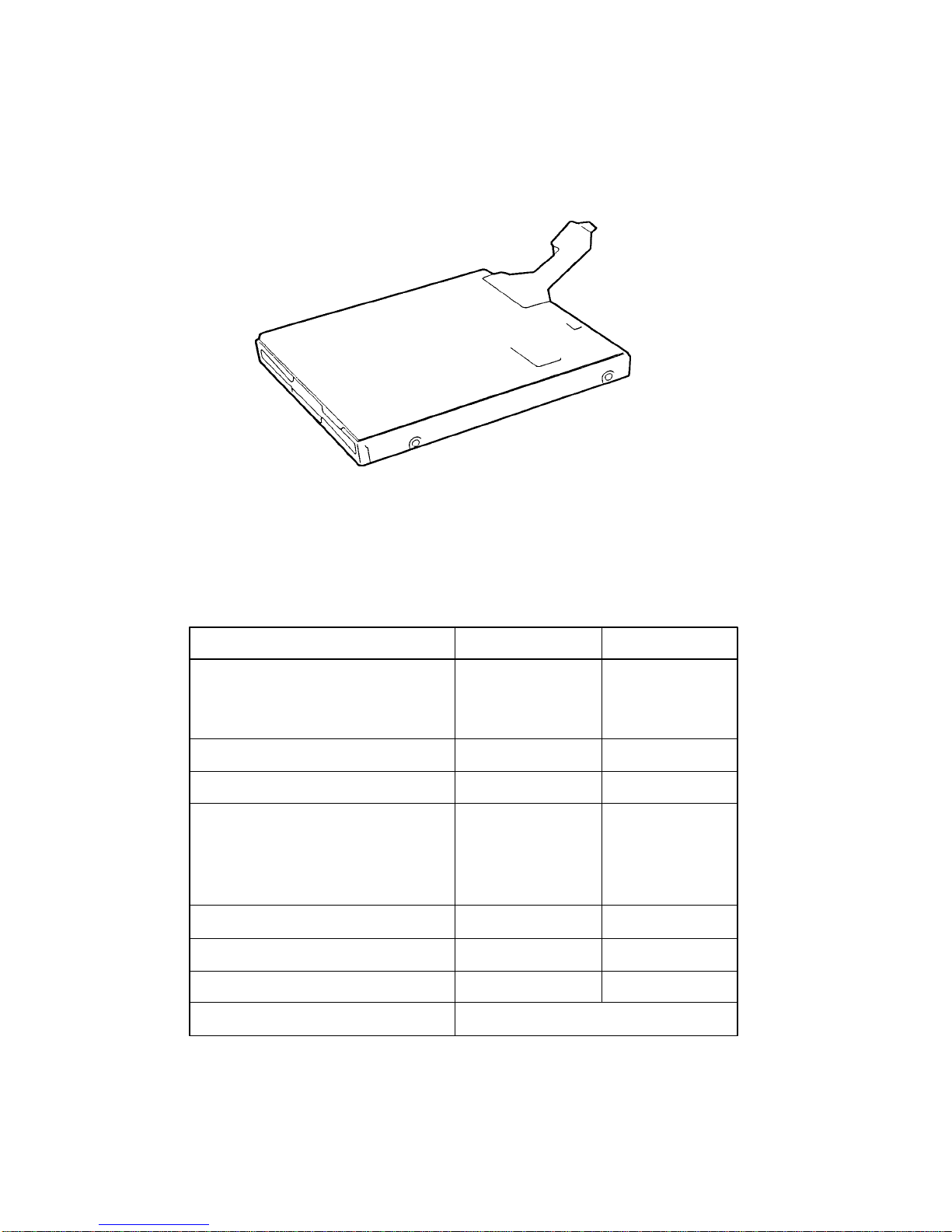
1.3 3.5-inch Floppy Disk Drive
The T1950 Series 3.5-inch Floppy Disk Drive (FDD) is a thin, high-performance reliable drive
that supports 720-KB (formatted) 2DD and 1.44-MB (formatted) 2HD 3.5-inch floppy disks.
The T1950 Series FDD is shown in Figure 1-4, and specifications are listed in Table 1-1.
Figure 1-4 3.5-inch FDD
Table 1-1 3.5-inch FDD Specifications
Item 2-MB mode 1-MB mode
Storage capacity (KB)
Unformatted 2,000 1,000
Formatted 1,311 737
Number of heads 2 2
Number of cylinders 80 80
Access time (ms)
Track to track 3 3
Average 181 181
Head settling time 15 15
Recording track density (tpi) 135 135
Data transfer rate (Kbps) 500 250
Rotation speed (rpm) 300 300
Recording method Modified Frequency Modulation (MFM)
1-7
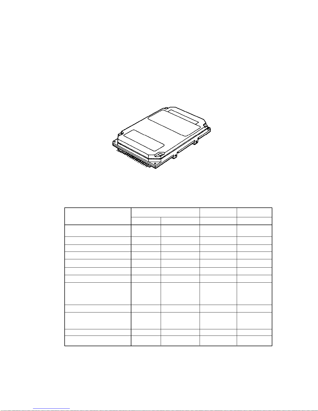
1.4 2.5-inch Hard Disk Drive
The Hard Disk Drive (HDD) is a random access non-volatile storage device. It has a nonremovable 2.5-inch magnetic disk and mini-winchester type magnetic heads.
The T1950/T1950CS supports a 120 or 200 MB HDD. The T1950CT supports a 200 or
320 MB HDD.
A T1950 Series HDD is shown in Figure 1-5, and specifications are listed in Table 1-2.
Figure 1-5 2.5-inch HDD
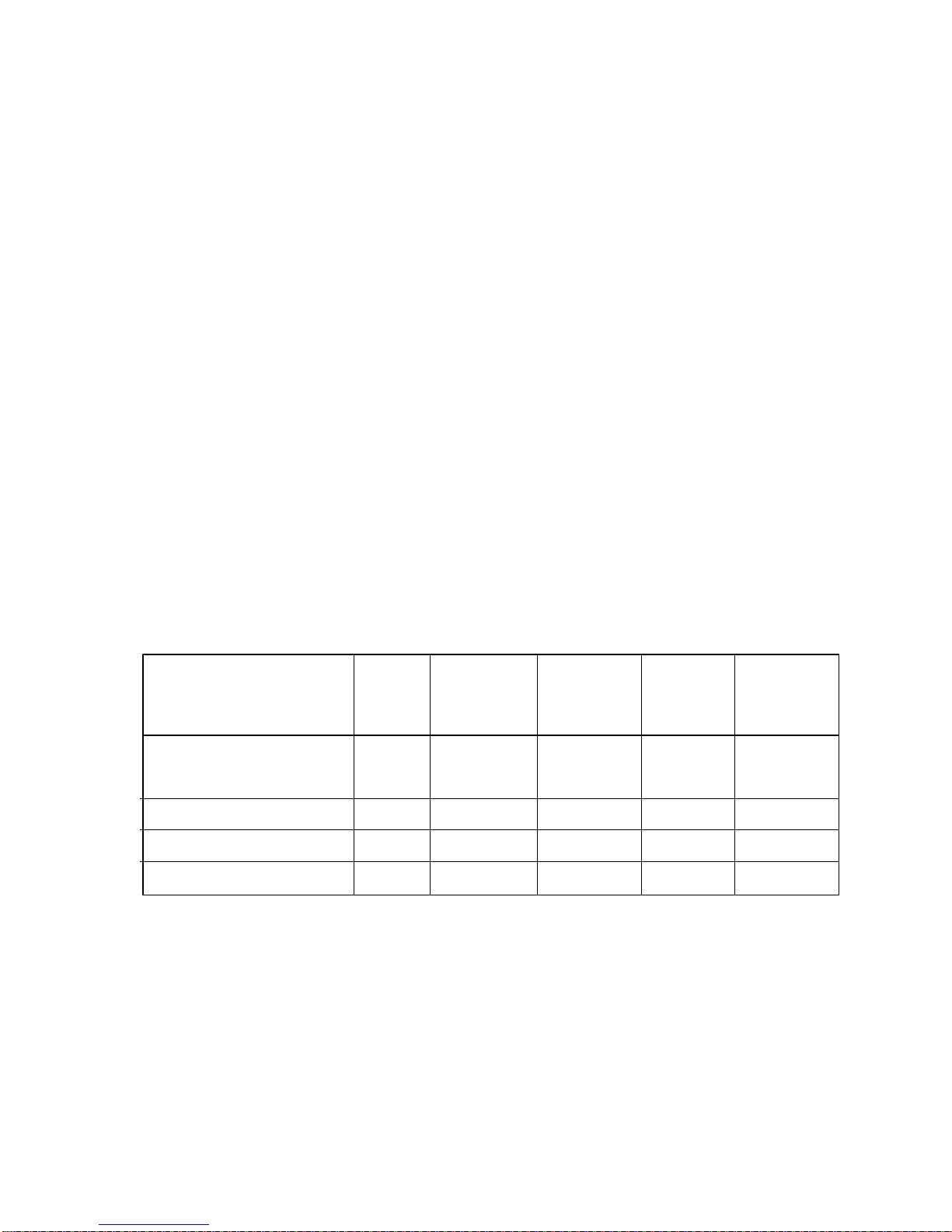
Table 1-2 2.5-inch HDD Specifications
120 MB 200 MB 320 MB
(CP2124) (MK2124FC) (MK2224FC) (MK2326FC)
Storage capacity (MB)
Formatted 121.6 130.1 213.0 340.0
Number of disks 2 2 2 3
Data heads 4 4 4 6
Data surfaces 4 4 4 6
Tracks per surface 1,123 1,155 1,560 1,830
Sectors per track 53 (+1) 55 (+1) – –
Bytes per sector 512 512 512 512
Access time (ms)
Track to track 3 5 3 3
Average 16 17 12 12
Maximum 30 36 25 25
Rotation speed (rpm) 3,743 3,200 4,000 4,200
Data transfer rate (bps)
To/from media 18 M 15.3 M 18.9 to 18.7 to
Interleave 1:1 1:1 1:1 1:1
Recording method 2-7 RLL 1-7 RLL 1-7 RLL 1-7 RLL
31.6 M 29.6 M
1-8
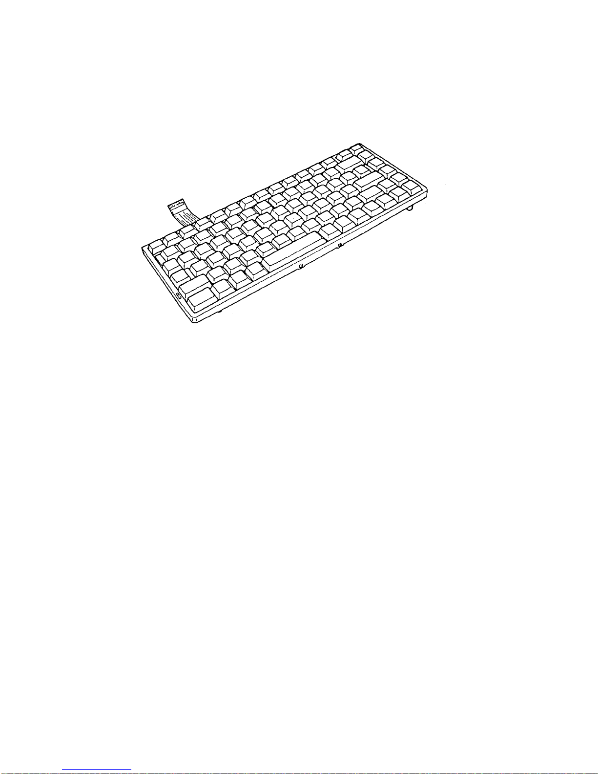
1.5 Keyboard
The 82-(USA) or 84-(European) keyboard is mounted on the T1950 Series system unit, and is
connected to the keyboard controller on the system board through a 19-pin flat cable. The
keyboard is shown in Figure 1-6.
Figure 1-6 Keyboard
1-9
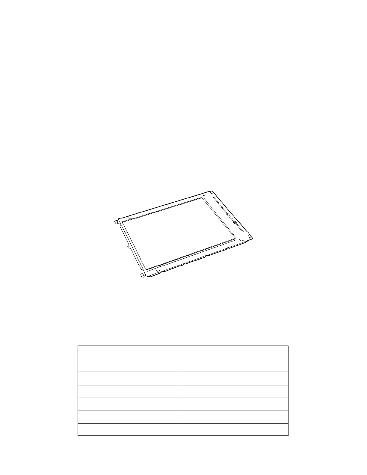
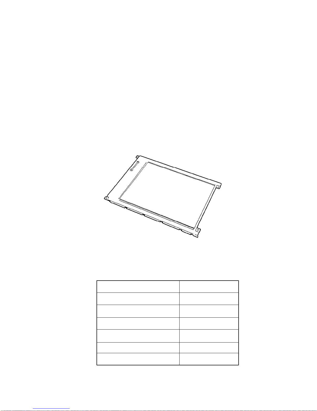
1.6 Monochrome LCD (T1950)
The monochrome Liquid Crystal Display (LCD) is composed of an LCD module, a Fluorescent Lamp (FL), and an FL inverter board.
1.6.1 Monochrome LCD Module
The T1950 monochrome LCD supports 640x480 pixels with a Video controller and 64 levels
of gray. The video controller includes the functions of the Video Graphics Array (VGA).
The LCD receives vertical and horizontal synchronizing signals, 8-bit data signals (4-bit upper
block data signal and 4-bit lower block data signal), and shift clock for data transmission. All
signals are CMOS-level compatible.
The sidelit LCD is shown in Figure 1-7, and its specifications are listed in Table 1-3.
Number of Dots (dots) 640 x 480
Dot pitch (mm) 0.30 (W) x 0.30 (H)
Display area (mm) 198 (W) x 150 (H)
Contrast 17:1 (typically)
FL current (mA) 5.0
FL frequency (KHz) 42
Figure 1-7 Monochrome LCD
Table 1-3 Monochrome LCD Specifications
Item Specifications
1-10
1.6.2 Monochrome Fluorescent Lamp (FL) Inverter Board
The FL inverter board supplies the high frequency current needed to illuminate the FL.
The specifications for the FL inverter board are listed in Table 1-4.
Table 1-4 Monochrome FL Inverter Board Specifications
Item Specifications
Input Voltage (VDC) 5
Power (W) 2.2
Voltage (VAC) 950
Output Current (mA) 4.2
Frequency (KHz) 38.5
1-11
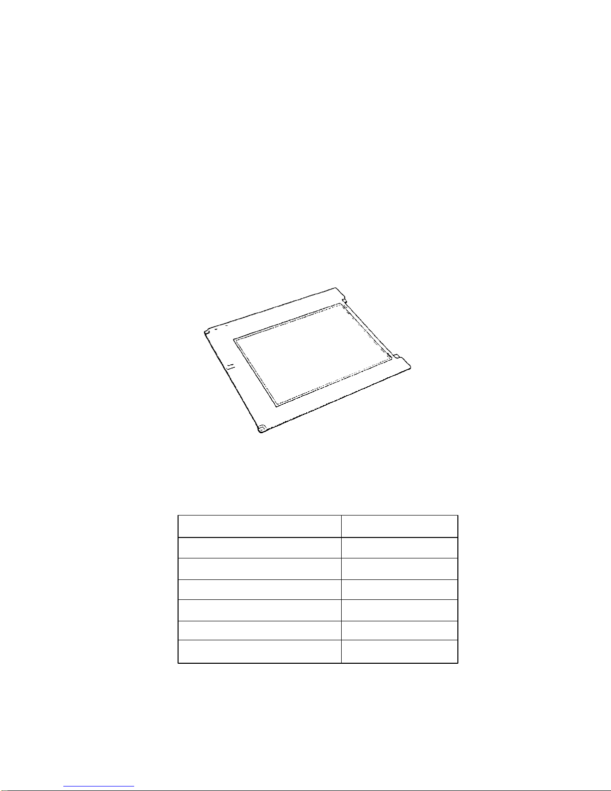
1.7 STN Color LCD (T1950CS)
The STN Color Liquid Crystal Display (LCD) contains an LCD module, a Fluorescent Lamp
(FL), and an FL inverter board.
1.7.1 STN Color LCD Module
The T1950CS STN color LCD is backlit and supports 640x480 pixels with a Video controller. This video controller includes the functions of Video Graphics Array (VGA).
The T1950CS’s LCD receives vertical and horizontal synchronizing signals, 16-bit data signal
(8-bit upper block data signal and 8-bit lower block data signal) and shift clock for data
transmission. All signals are CMOS-level compatible.
The STN LCD is shown in Figure 1-8, and specifications for the LCD are listed in Table 1-5.
Figure 1-8 STN Color LCD
Table 1-5 STN Color LCD Specifications
Item Specifications
Number of Dots (dots) 640x480
Dot pitch (mm) 0.3 (W)x0.3 (H)
Display area (mm) 195 (W)x147 (H)
Contrast 18:1 (Typically)
FL current (mA) 5.0
FL frequency (KHz) 47
1-12
1.7.2 STN Color Fluorescent Lamp (FL) Inverter Board
The FL inverter board supplies high frequency current to light the LCD’s Fluorescent Lamp.
The specifications for the FL inverter are listed in Table 1-6.
Table 1-6 STN Color FL Inverter Board Specifications
Item Specifications
Input Voltage (VDC) 5
Power (W) 6
Output Voltage (VAC) 1,000
Current (mA) 5.0 x 2
Frequency (KHz) 42
1-13
1.8 TFT Color LCD (T1950CT)
The TFT Color Liquid Crystal Display (LCD) contains an LCD module, a Fluorescent Lamp
(FL), and an FL inverter board.
1.8.1 TFT Color LCD Module
The T1950CT TFT color LCD supports 640x480 pixels with an internal display controller and
512 colors for graphics and characters. This controller includes the functions of Video
Graphics Array (VGA) and Super VGA (SVGA) for external display.
The T1950CT’s LCD receives 9-bit data signals, data enable signals, and shift clock for data
transmission. All signals are CMOS-level compatible.
The TFT LCD is shown in Figure 1-9, and specifications are listed in Table 1-7.
Figure 1-9 TFT Color LCD
Table 1-7 TFT Color LCD Specifications
Item Specifications
Number of dots (dots) 640x480
Dot pitch (mm) 0.27 (W)x0.27 (H)
Display area (mm) 171 (W)x130 (H)
Contrast 60:1 (minimum)
FL current (mA) 5.0
FL frequency (KHz) 47
1-14
1.8.2 TFT Color Fluorescent Lamp (FL) Inverter Board
The FL inverter board supplies high frequency current to light the LCD’s Fluorescent Lamp.
The specifications for the FL inverter are listed in Table 1-8.
Table 1-8 FL Inverter Board Specifications
Item Specifications
Input Voltage (VDC) 5
Power (W) 3
Output Voltage (VAC) 1,100
Current (mA) 5.0
Frequency (KHz) 47
1-15
1.9 Power Supply
The power supply uses a microprocessor to monitor and regulate the voltages used within the
T1950 Series computers. The power supply contains the following functions:
1. Determines if the AC adapter or battery is connected to the computer.
2. Detects DC output and circuit malfunctions.
3. Controls the LED indicator and speaker.
4. Turns the battery charging system on and off and detects a fully charged
battery.
5. Determines if the power can be turned on and off.
6. Provides more accurate detection of a low battery.
7. Calculates the remaining battery capacity.
The power supply output rating is specified in Table 1-9.
Table 1-9 Power Supply Output Rating
DC Regulation Maximum
Use for Name voltage tolerance current Ripple
(V) (%) (mA) (mV)
System logic, FDD, HDD, VCC +5 ±5 3,500 100
Display
RS-232C, Flash ROM 12V +12 ±5 120 240
RAM, CPU B3V +3.3 ±5 755 66
RS-232C M12V –7 to –12.6 – 10 –
1-16
1.10 Batteries
The T1950 Series has three types of batteries:
❑ Main battery pack
❑ Backup battery
❑ Real Time Clock (RTC) battery
Specifications for these batteries are listed in Table 1-10.
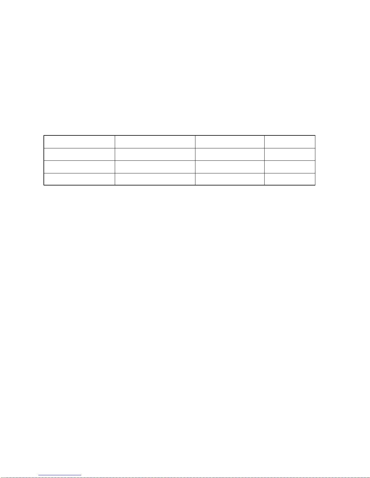
Table 1-10 Battery Specifications
Battery name Material Output voltage Capacity
Main battery Nickel Metal Hydride 12 V 2,400 mAH
Backup battery Nickel Metal Hydride 1.2 V 1,100 mAH
RTC battery Lithium-Vanadium 3.0 V 50 mAH
1.10.1 Battery Indicator
The battery indicator is located on the top cover, and shows the status of the removable
battery pack, power supply and AC adapter.
The status of each can be determined by color:
Orange The battery is being charged. (AC adapter is attached.)
Green The battery is fully charged. (AC adapter is attached.)
No light The AC adapter is disconnected from the computer or the AC adapter is
connected, but it cannot charge the battery for one of the following reasons:
❍ The battery is extremely hot. Allow the computer and the battery to
reach room temperature before attempting to charge the battery.
❍ The battery is almost fully discharged. The battery will not begin
charging immediately in this state, it will begin charging a few
minutes after the AC adapter is connected.
The AC adapter is not receiving power.
❍
1.10.2 Main Battery
The removable main battery pack is the computer’s main power source when the AC adapter
is not attached. The main battery recharges the backup battery when the system’s power is
on. The backup and main battery maintain the state of the computer when you enable
AutoResume, and they maintain the information in Hard RAM.
1-17
1.10.2.1 Battery Charging Control
Battery charging is controlled by a microprocessor that is mounted on the power supply. The
microprocessor controls whether the charge is on or off and detects a full charge when the AC
adapter and battery are attached to the computer. The system charges the battery using quick
charge or trickle charge.
When the AC adapter is attached, there are two types of charge: quick charge when the
system is powered off, and trickle charge when the system is powered on. Table 1-11 shows
the charging time period of the main battery.
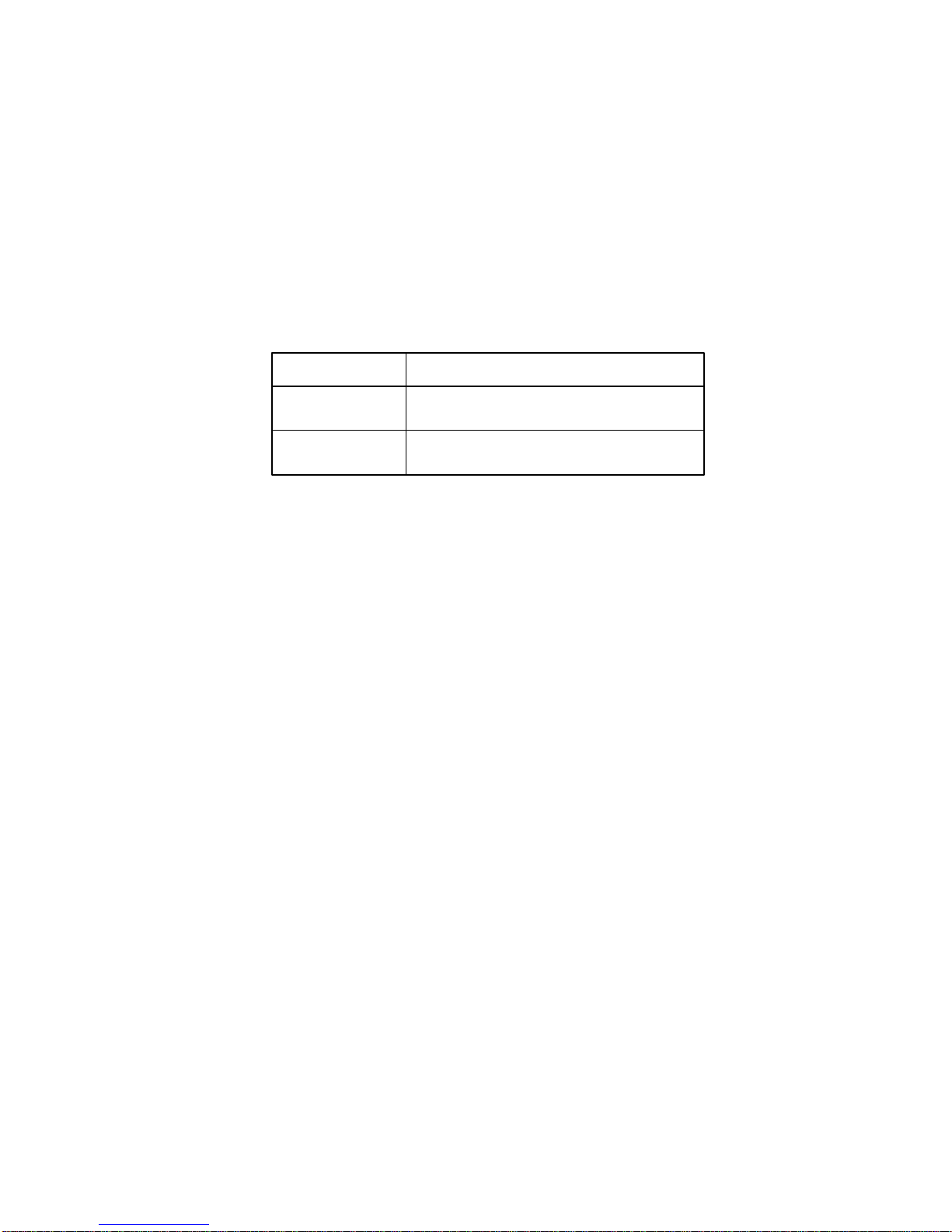
Table 1-11 Time Required for Battery Charges
Charging time
Quick charge About 2.3 hours (T1950)
(power off) About 1.4 hours (T1950CS/T1950CT)
Trickle charge About 48 hours
(power on)
❏ Quick Battery Charge
If one of the following occurs, the battery quick-charge process stops.
1. The battery becomes fully charged
2. The AC adapter or battery is removed.
3. The battery or AC adapter output voltage is abnormal.
4. The charge current is abnormal.
❏ Trickle Battery Charge
When the main battery is fully charged and the AC adapter is attached, the power supply
microprocessor automatically changes quick charge to trickle charge.
1.10.3 Backup Battery
The backup battery maintains data for AutoResume. The power source used to back-up the
AutoResume data is determined according to the following priority:
AC adapter > Main battery > Backup battery
The backup battery is charged by the main battery or AC adapter when the system is powered
on. Table 1-12 shows the charging time and data preservation period of the backup battery.
1-18
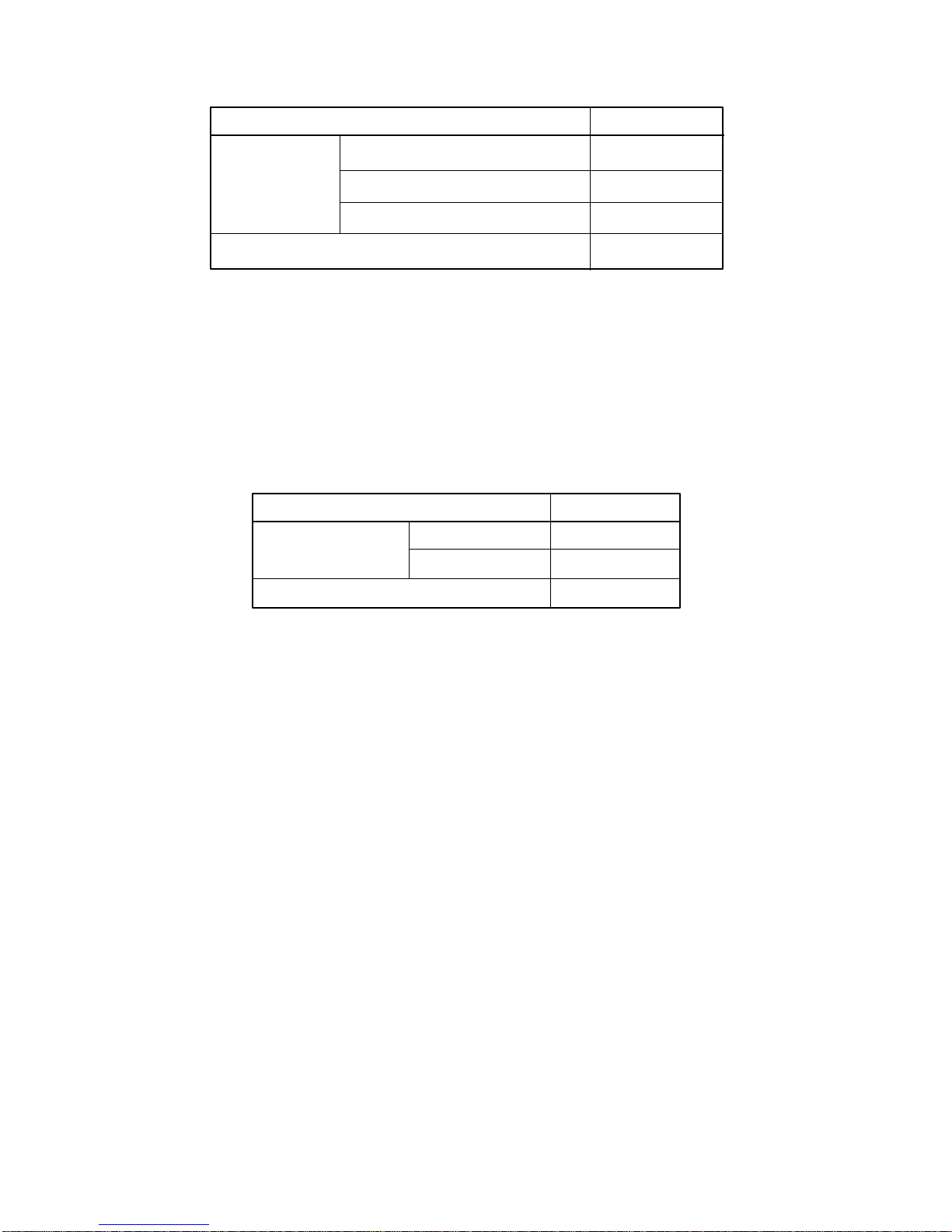
Table 1-12 Backup Battery Charging/Data Preservation Time
Time
Charging Time Power On 16 H
Power Off (with AC Adapter) 60 H
Power Off (Without AC Adapter) Doesn’t charge
Data preservation period (full charge) 8 H
1.10.4 RTC Battery
The RTC battery provides power to keep the current date, time and other setup information in
memory while the computer is turned off. Table 1-13 shows the charging time and data
preservation period of the RTC battery.
Table 1-13 RTC Battery Charging/Data Preservation Time
Time
Charging Time Power On 48 H
Power Off Doesn’t charge
Data preservation period (full charge) 1 month

2-1
2.1 Troubleshooting
Chapter 2 describes how to determine if a Field Replaceable Unit (FRU) in the T1900/
T1900C is causing the computer to malfunction. FRUs covered include the:
1. Upper and Lower System Boards
2. Floppy Disk Drive
3. Hard Disk Drive
4. Keyboard
5. Display
The Diagnostics Disk operations are described in Chapter 3 and detailed replacement
procedures are given in Chapter 4.
The following tools are necessary for implementing the troubleshooting procedures:
1. T1900/T1900C Diagnostics Disk
2. Phillips head screwdriver (2 mm)
3. Toshiba MS-DOS system disk(s)
4. 2DD or 2HD formatted work disk for floppy disk drive testing
5. Cleaning kit for floppy disk drive troubleshooting
6. Printer port LED
7. RS-232-C wraparound connector
8. Printer wraparound connector
9. Multimeter
10. External 5.25-inch floppy disk drive
11. External CRT

2-2
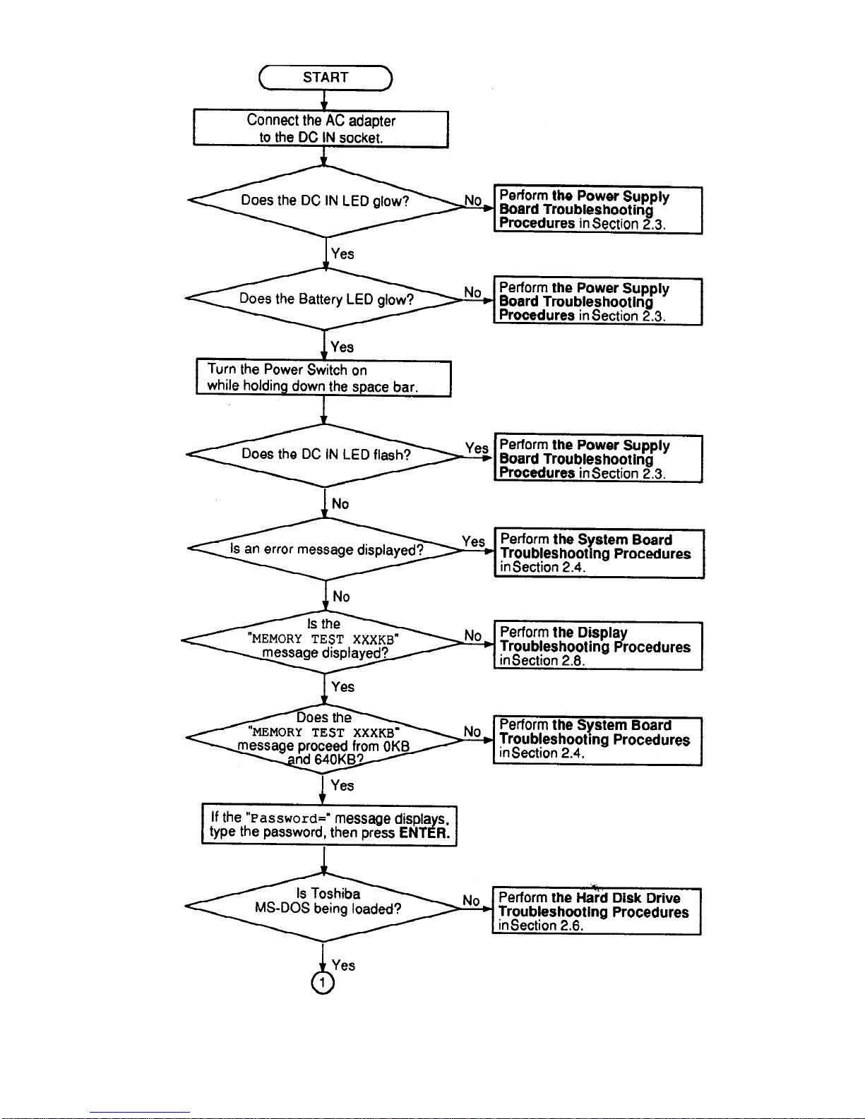
2.2 Troubleshooting Flowchart
Use the flowchart in Figure 2-1 as a guide for determining which troubleshooting procedures to
execute. Before going through the flowchart steps, verify the following:
❑ Ask the user if a password is registered, and if it is, ask him or her to enter the
password. If the user has forgotten the password, connect the printer port wraparound board (F31PRT), then turn the POWER switch on. The computer will
override the password function by erasing the current password.
❑ Verify with the customer that Toshiba MS-DOS is installed on the hard disk.
Non-Toshiba operating systems can cause the computer to malfunction.
❑ Make sure all optional equipment is disconnected from the computer.
❑ Make sure the floppy disk drive is empty.
2-3
Figure 2-1 Troubleshooting Flowchart (1/2)
2-4
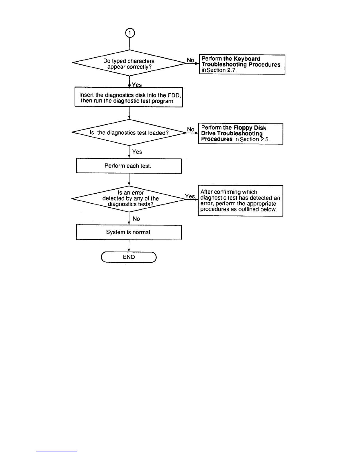
Figure 2-1 Troubleshooting Flowchart (2/2)
If the diagnostics program cannot detect an error, the problem may be intermittent. The Running
Test program should be executed several times to isolate the problem. Check the Log Utilities
function to confirm which diagnostic test detected an error(s), then perform the appropriate
troubleshooting procedures as follows:
1. If an error is detected on the System Test, Memory Test, Display Test, ASYNC
Test, Printer Test, or Real Timer Test, perform the System Board Troubleshooting
Procedures in Section 2.4.
2. If an error is detected on the Keyboard Test, perform the Keyboard Troubleshooting Procedures in Section 2.7.
3. If an error is detected on the Floppy Disk Test, perform the Floppy Disk Drive
Troubleshooting Procedures in Section 2.5.
4. If an error is detected on the Hard Disk Test, perform the Hard Disk Drive
Troubleshooting Procedures in Section 2.6.

2-5
2.3 Power Supply Troubleshooting
The T1900/T1900C’s power supply controls many functions and components in the computer.
To determine if the power supply is functioning properly, start with Procedure 1 and continue
with the other procedures as instructed. Procedures described in this section are:
Procedure 1: DC IN LED Indicator Check
Procedure 2: Battery LED Indicator Check
Procedure 3: System PCB Replacement Check
Procedure 1 DC IN LED Indicator Check
The T1900/T1900C’s AC adapter converts AC power to DC power and contains a charging
circuit which charges the computer’s batteries. The adapter connects to the DC IN socket
connector on the left side of the computer. When it is connected and the power is turned off,
the AC adapter charges the batteries.
The DC IN indicator displays whether or not the AC adapter is connected and supplying
power.
❑ When the DC IN indicator is orange, the AC adapter is connected and supplying
power to the computer.
❑ If the DC IN indicator does not light, the AC adapter is not supplying power to
the computer, or is not attached to the computer, go to Check 1.
❑ If the DC IN indicator is flashing orange, the AC adapter’s voltage supply is
abnormal or the power supply is not functioning properly, go to Check 1.
If any of the above indicator conditions are abnormal, make sure the LED indicator lights are
not burned out before performing the following Checks.
Check 1 Make sure the correct AC adapter’s cable is firmly plugged into the DC IN socket
on the back of the computer.
T1900 (PA2417U), 1.1 A T1900C (PA2478U), 1.7 A
Check 2 If the DC IN indicator flashes orange when the AC adapter is connected, its volt-
age output is abnormal. Connect a new AC adapter and turn the computer on again
to verify the indicator condition.

2-6
Check 3 The battery pack may be malfunctioning. Replace the battery pack with a new one
and turn the computer on again. If the problem still exists, perform Check 4.
Check 4 Place the computer in an environment between –20°C and 70°C until the unit is at
the ambient temperature. Repeat the steps which caused the computer to operate
abnormally. If the same problem still appears, perform Procedure 3.
Procedure 2 Battery LED Indicator Check
The battery LED indicator shows the battery charging status. The Battery LED, identified by a
battery icon on the front of the computer, glows amber when the AC adapter is charging the
computer’s battery pack.
❑ If the Battery LED indicator glows green, the AC adapter is connected and the
battery is fully charged.
❑ If the Battery LED indicator glows amber, the AC adapter is connected and the
battery is being charged.
❑ If the Battery LED indicator does not glow, go to Check 1.
Check 1 Make sure the AC adapter’s cable and AC cord are firmly plugged into the DC IN
socket and wall outlet. If these cables are connected correctly, go to Check 2.
Check 2 Make sure the battery pack is installed in the computer correctly. If the battery
pack is installed correctly, go to Check 3.
Check 3 Remove the battery pack and check that the battery terminal is clean and not bent.
❑ If the terminal appears dirty, clean it gently with a cotton swab dipped in
alcohol.
❑ If the terminal looks bent or damaged, replace the lower system board.
❑ If the battery terminal is clean and not bent, go to Check 4.
Check 4 Connect a new AC adapter. If the battery LED indicator still does not glow, go to
Check 5.
Check 5 Install a new battery pack. If the battery LED indicator still does not glow, go to
Procedure 3.

2-7
Procedure 3 Power Supply Replacement Check
The power supply is built into the lower system board. If the power supply is damaged, the
lower system board must be replaced.
Refer to Chapter 4 for instructions on how to disassemble the T1900/T1900C, then perform the
following check:
Check 1 Replace the lower system board with a new one and restart the system. If the
problem still exists, go to Check 2.
Check 2 Replace the upper system board with a new one and restart the system. If the
problem still exists, other FRUs may be damaged.

2-8
2.4 System Board Troubleshooting
This section describes how to determine if the upper or lower system board is defective or not
functioning properly. Start with Procedure 1 and continue with the other procedures as
instructed. Procedures described in this section include:
Procedure 1: Message Check
Procedure 2: Printer Port LED Check in Boot Mode
Procedure 3: Printer Port LED Check in Resume Mode
Procedure 4: Diagnostic Test Program Execution Check
Procedure 5: System Board Replacement Check
Procedure 1 Message Check
When the power is turned on, the system performs the Initial Reliability Test (IRT) installed in
the BIOS ROM. The IRT tests and initializes each IC on the system boards.
❑ If an error message is shown on the display, perform Check 1.
❑ If there is no error message, go to Procedure 2.
❑ If Toshiba MS-DOS is properly loaded, go to Procedure 3.
Check 1 If one of the following error messages is displayed on the screen, press the F1 key
as the message instructs.
(a) *** Error in CMOS. Bad HDD type ***
Check system. Then press [F1] key ......
(b) *** Error in CMOS. Bad battery ***
Check system. Then press [F1] key ......
(c) *** Error in CMOS. Bad check sum ***
Check system. Then press [F1] key ......
(d) *** Error in CMOS. Bad memory size ***
Check system. Then press [F1] key ......
(e) *** Error in CMOS. Bad time function ***
Check system. Then press [F1] key ......
These errors occur when the system configuration preserved in the RTC memory
(CMOS-type memory) is not the same as the actual configuration or when the data
is lost.
If you press the F1 key as the message instructs, the system configuration in the
RTC memory configuration is set to the default setting. If Error Message (b)
appears often when the power is turned on, replace the RTC battery. If any other
error message is displayed, perform Check 2.
2-9
Check 2 If either of the following error messages [(a) or (b)] is displayed on the screen,
press any key as the message instructs.
(a) WARNING: RESUME FAILURE.
PRESS ANY KEY TO CONTINUE.
(b) WARNING: DATA IN HARD-RAM WAS LOST.
YOU MUST FORMAT HARD-RAM BEFORE USE.
PRESS ANY KEY TO CONTINUE.
Error Message (a) appears when data stored in RAM under the resume function is
lost because the battery has become discharged or the system PCB is damaged. Go
to Procedure 3.
Error Message (b) appears when the error is detected during a read test of the
Hard RAM or the data in Hard RAM is lost because the battery has become
discharged.
If any other message appears, perform Check 3.
Check 3 The IRT checks the system boards. When the IRT detects an error, the system stops
or an error message appears. Refer to Table 2-1 for a list of error messages.
Table 2-1 IRT Error Messages (1/2)
No. Error Message
1 TIMER CH.2 OUT ERROR
2 PIT ERROR
3 MEMORY REFRESH ERROR
4 FIRST 64KB MEMORY ERROR
5 RTC ERROR
6 CRTC ERROR
7 VRAM ERROR
8 KBC ERROR
9 SYSTEM MEMORY ERROR
10 SYSTEM MEMORY PARITY ERROR
11 EXTENDED MEMORY ERROR
12 EXTENDED MEMORY PARITY ERROR
13 DMA PAGE REGISTER ERROR
14 DMAC #1 ERROR
15 DMAC #2 ERROR
16 PIC #1 ERROR

2-10
Table 2-1 IRT Error Messages (2/2)
No. Error Message
17 PIC #2 ERROR
18 KEYBOARD ERROR
19 KBC ERROR
20 HDC ERROR
21 HDD #0 ERROR
22 HDD #1 ERROR
23 NO FDD ERROR
24 FDD ERROR
25 TIMER INTERRUPT ERROR
26 RTC UPDATE ERROR
If any of the following error messages is displayed, go to Procedure 5:
❑
1 through 17, 19, 20, 25 or 26
❑ If Error Message 18 is displayed, go to the Keyboard Troubleshooting Proce-
dures in Section 2.7.
❑ If Error Message 21 or 22 is displayed, go to the HDD Troubleshooting
Procedures in Section 2.6.
❑ If Error Message 23 or 24 is displayed, go to the FDD Troubleshooting
Procedures in Section 2.5.
2-11
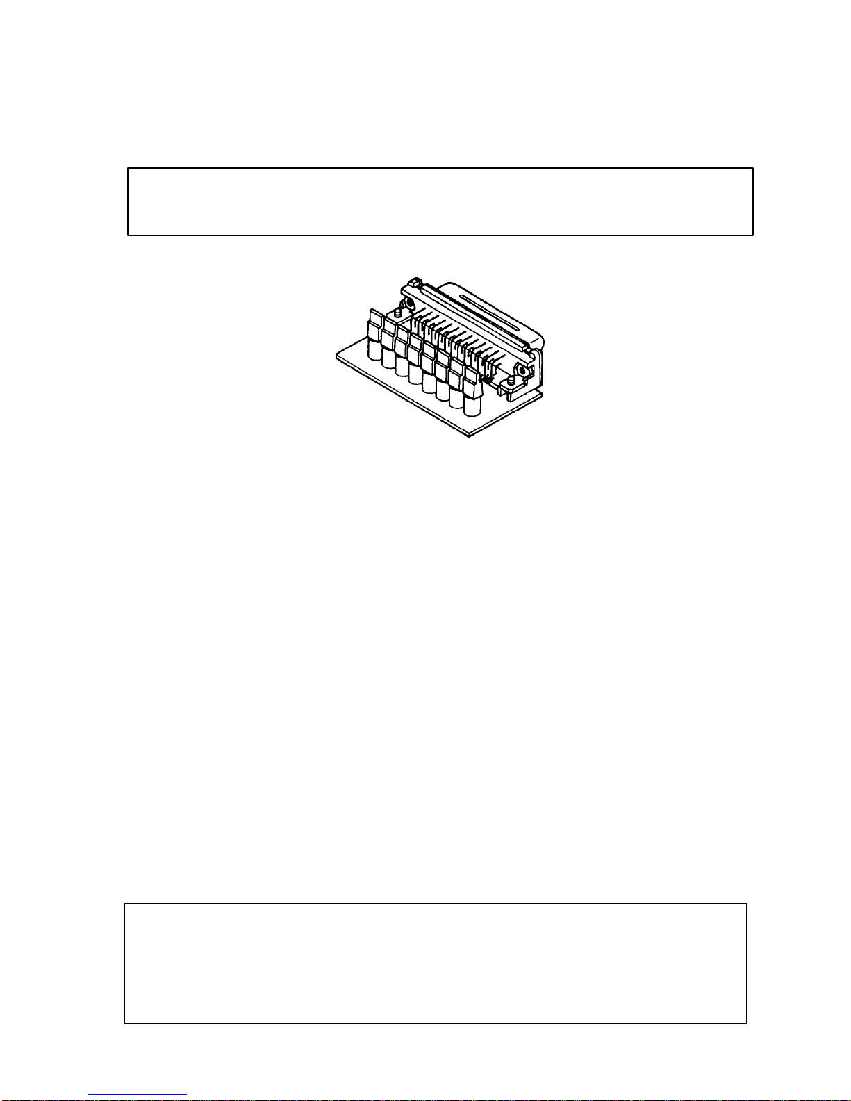
Procedure 2 Printer Port LED Check in Boot Mode
The printer port LED displays the IRT status and test status by turning lights on and off as an
eight-digit binary value for boot mode. Figure 2-2 shows the printer port LED.
NOTE: When performing this check, the external FDD/PRT option in the SETUP
program must be set to PRT and the computer set to boot mode.
Figure 2-2 Printer Port LED
To use the printer port LED, follow these steps:
1. Turn on the T1900/T1900C’s power, then set it to boot mode.
2. Turn off the computer.
3. Plug the printer port LED into the computer’s PRT/FDD connector.
4. Hold down the space bar and turn on the T1900/T1900C’s power.
5. Read the LED status from left to right as you are facing the back of the computer.
6. Convert the status from binary to hexadecimal notation.
7. If the final LED status is FFh (normal status), go to Procedure 3.
8. If the final LED status matches any of the test status values in Table 2-2, go to
Check 1.
NOTE: If an error condition is detected by the IRT test, the printer port LED
displays an error code after the IRT test ends. For example, when the printer port
LED displays 22 and halts, the IRT test has already completed the KBC test. In this
instance, the IRT indicates an error has been detected during the system memory
test.
2-12
Table 2-2 Printer Port LED Boot Mode Error Status (1/2)
Error Status Test Item Message
01H Pre-init for warm start —
test
05H PIT test TIMER CH.2 OUT ERROR
PIT ERROR
READ DATA = XXH
WRITE DATA = XXH
06H PIT initialization —
07H PIT function test MEMORY REFRESH ERROR
0AH First 64KB memory test FIRST 64KB MEMORY ERROR
0BH System memory —
initialization
0DH Interrupt vector —
initialization
15H RTC test RTC ERROR
READ DATA = XXH
WRITE DATA = XXH
16H CMOS RAM test ****Error in CMOS. Bad battery****
****Error in CMOS. Bad check sum****
****Error in CMOS. Bad configuration****
****Error in CMOS. Bad memory size****
****Error in CMOS. Bad HDD type****
****Error in CMOS. Bad time function****
Check system. Then press [F1] key
18H PIC initialization —
1FH Display initialization CRTC ERROR
VRAM ERROR
READ DATA = XXXXXXXXH
WRITE DATA = XXXXXXXXH
22H KBC test KBC ERROR
25H System memory test SYSTEM MEMORY ERROR
ADDRESS = XXXXXXXXH
READ DATA = XXXXXXXXH
WRITE DATA = XXXXXXXXH
SYSTEM MEMORY PARITY ERROR
ADDRESS = XXXX0000H - XXXXFFFFH
30H Extended memory test EXTENDED MEMORY ERROR
ADDRESS = XXXXXXXXH
READ DATA = XXXXXXXXH
WRITE DATA = XXXXXXXXH
EXTENDED MEMORY PARITY ERROR
ADDRESS = XXXX0000H - XXXXFFFFH
40H DMA page register test DMA PAGE REGISTER ERROR
READ DATA = XXH
WRITE DATA = XXH
 Loading...