

Page 1

TOSHIBA
Satellite T130/T110
Satellite Pro T130/T110
PORTEGE T130/T110
Portable Personal Computer
User's Manual
Page 2

Copyright
© 2009 by TOSHIBA Corporation. All rights reserved. Under the copyright
laws, this manual cannot be reproduced in any form without the prior
written permission of TOSHIBA. No patent liability is assumed, with respect
to the use of the information contained herein.
TOSHIBA Satellite T130/T110, Satellite Pro T130/T110, PORTEGE T130/
T110 Series Portable Personal Computer User's Manual
First edition July 2009
Copyright authority for music, movies, computer programs, databases, and
other intellectual property covered by copyright laws belongs to the author
or the copyright owner. Copyrighted material can be reproduced only for
personal use or use within the home. Any other use beyond that stipulated
above (including conversion to digital format, alteration, transfer of copied
material and distribution on a network) without the permission of the
copyright owner is a violation of copyright or author's rights and is subject to
civil damages or criminal action. Please comply with copyright laws in
making any reproduction from this manual.
Please note that you may infringe the owner's rights protected by the
copyright laws if you use the screen mode switching functions (e.g. Wide
mode, Wide Zoom mode, etc.) of this product to display enlarged images/
video at coffee shops or hotels for the purposes of profits or providing these
to the public.
Disclaimer
This manual has been validated and reviewed for accuracy. The
instructions and descriptions it contains are accurate for the TOSHIBA
Satellite T130/T110, Satellite Pro T130/T110, PORTEGE T130/T110 Series
Portable Personal Computer at the time of this manual's production.
However, succeeding computers and manuals are subject to change
without notice. TOSHIBA assumes no liability for damages incurred directly
or indirectly from errors, omissions or discrepancies between the computer
and the manual.
ii User’s Manual
Page 3

Trademarks
IBM is a registered trademark and IBM PC is a trademark of International
Business Machines Corporation.
Microsoft, Windows and Windows logo are either registered trademarks or
trademarks of Microsoft Corporation.
DirectX, AcriveDesktop, DirectShow, and Windows Media are registered
trademarks of Microsoft Corporation.
Intel, Intel Core, Celeron, Centrino and Pentium are trademarks or
registered trademarks of Intel Corporation.
Adobe is either a registered trademark or trademark of Adobe Systems
Incorporated in the United States and/or other countries.
Bluetooth is a registered trademark owned by its proprietor and used by
TOSHIBA under license.
ConfigFree is a trademark of TOSHIBA Corporation.
HDMI, the HDMI logo and High-Definition Multimedia Interface are
trademarks or registered trademarks of HDMI Licensing LLC.
Memory Stick, Memory Stick PRO, Memory Stick PRO Duo and i.LINK are
trademarks or registered trademarks of Sony Corporation.
MultiMediaCard and MMC are trademarks of MultiMediaCard Association.
Secure Digital and SD are trademarks of SD Card Association.
xD-Picture Card is a trademark of FUJIFILM Corporation.
Wi-Fi is a registered trademark of the Wi-Fi Alliance.
Other trademarks and registered trademarks not listed above may be used
in this manual.
Safety Instructions
Use the following safety guidelines to help protect yourself and your
computer.
User’s Manual iii
Page 4

When Using Your Computer
Do not operate your portable computer for an extended period of time with
the base resting directly on your body. With extended operation, heat can
potentially build up in the base. Allowing sustained contact with the skin
could cause discomfort or, eventually, a burn.
■ Do not attempt to service the computer yourself. Always follow
installation instructions closely.
■ Do not carry a battery in your pocket, purse, or other container where
metal objects (such as car keys) could short-circuit the battery
terminals. The resulting excessive current follow can cause extremely
high temperatures and may result in damage from burns.
■ Be sure that nothing rests on your AC adaptor's power cable and that
the cable is not located where it can be tripped over or stepped on.
■ Place the AC adaptor in a ventilated area, such as a desk top or on the
floor, when you use it to run the computer or to charge the battery. Do
not cover the AC adaptor with papers or other items that will reduce
cooling; also, do not use the AC adaptor while it is inside a carrying
case.
■ Use only the AC adaptor and batteries that are approved for use with
this computer. Use of another type of battery or AC adaptor may risk fire
or explosion.
■ Before you connect the computer to a power source, ensure that the
voltage rating of the AC adaptor matches that of the available power
source. 115 V/ 60 Hz in most of North and South America and some Far
Eastern countries such as Taiwan. 100 V/50 Hz in eastern Japan and
100 V/60 Hz in western Japan. 230 V/50 Hz in most of Europe, the
Middle East, and the Far East.
■ If you use an extension cable with your AC adaptor, ensure that the total
ampere rating of the products plugged in to the extension cable does
not exceed the ampere rating of the extension cable.
■ To remove power from the computer, turn it off, disconnect the AC
adaptor from the electrical outlet, and remove the battery.
■ To help avoid the potential hazard of electric shock, do not connect or
disconnect any cables or perform maintenance or reconfiguration of this
product during and electrical storm.
■ When setting up the computer for work, place it on a level surface.
iv User’s Manual
Page 5

FCC information
FCC notice "Declaration of Conformity Information"
This equipment has been tested and found to comply with the limits for a
Class B digital device, pursuant to part 15 of the FCC rules. These limits
are designed to provide reasonable protection against harmful interference
in a residential installation. This equipment generates, uses and can radiate
radio frequency energy and, if not installed and used in accordance with the
instructions, may cause harmful interference to radio communications.
However, there is no guarantee that interference will not occur in a
particular installation. If this equipment does cause harmful interference to
radio or television reception, which can be determined by turning the
equipment off and on, the user is encouraged to try to correct the
interference by one or more of the following measures:
■ Reorient or relocate the receiving antenna.
■ Increase the separation between the equipment and receiver.
■ Connect the equipment into an outlet on a circuit different from that to
which the receiver is connected.
■ Consult the dealer or an experienced radio/TV technician for help.
Only peripherals complying with the FCC class B limits may be attached to
this equipment. Operation with non-compliant peripherals or peripherals
not recommended by TOSHIBA is likely to result in interference to radio
and TV reception. Shielded cables must be used between the external
devices and the computer's external monitor port, USB port, serial port,
parallel port, PS/2 mouse/keyboard port and microphone jack. Changes or
modifications made to this equipment, not expressly approved by
TOSHIBA or parties authorized by TOSHIBA could void the user's
authority to operate the equipment.
FCC conditions
This device complies with part 15 of the FCC Rules. Operation is subject to
the following two conditions:
1. This device may not cause harmful interference.
2. This device must accept any interference received, including
interference that may cause undesired operation.
Contact
Address: TOSHIBA America Information Systems, Inc.
9740 Irvine Boulevard
Irvine, California 92618-1697
Telephone: (949) 583-3000
User’s Manual v
Page 6
EU Declaration of Conformity
TOSHIBA declares that this product conforms to the following Standards:
Supplementary
Information:
This product is carrying the CE-Mark in accordance with the related
European Directives. Responsible for CE-Marking is TOSHIBA Europe,
Hammfelddamm 8, 41460 Neuss, Germany.
Regulatory and agency labels may be located computer bottom or under
battery.
"The product complies with the requirements of
the Low Voltage Directive 2006/95/EC, the EMC
Directive 2004/108/EC and/or the R&TTE
Directive 1999/5/EC."
VCCI Class B Information
ߎߩⵝ⟎ߪޔࠢࠬ㧮ᖱႎᛛⴚⵝ⟎ߢߔޕߎߩⵝ⟎ߪޔኅᐸⅣႺߢ↪ߔࠆ
ߎߣࠍ⋡⊛ߣߒߡ߹ߔ߇ޔߎߩⵝ⟎߇ࠫࠝ߿࠹ࡆ࡚ࠫࡦฃାᯏߦㄭធ
ߒߡ↪ߐࠇࠆߣޔฃା㓚ኂࠍᒁ߈ߎߔߎߣ߇ࠅ߹ߔޕ
ขᛒ⺑ᦠߦᓥߞߡᱜߒขࠅᛒࠍߒߡߊߛߐޕ VCCI-B
vi User’s Manual
Page 7
Following information is only valid for EU-member States:
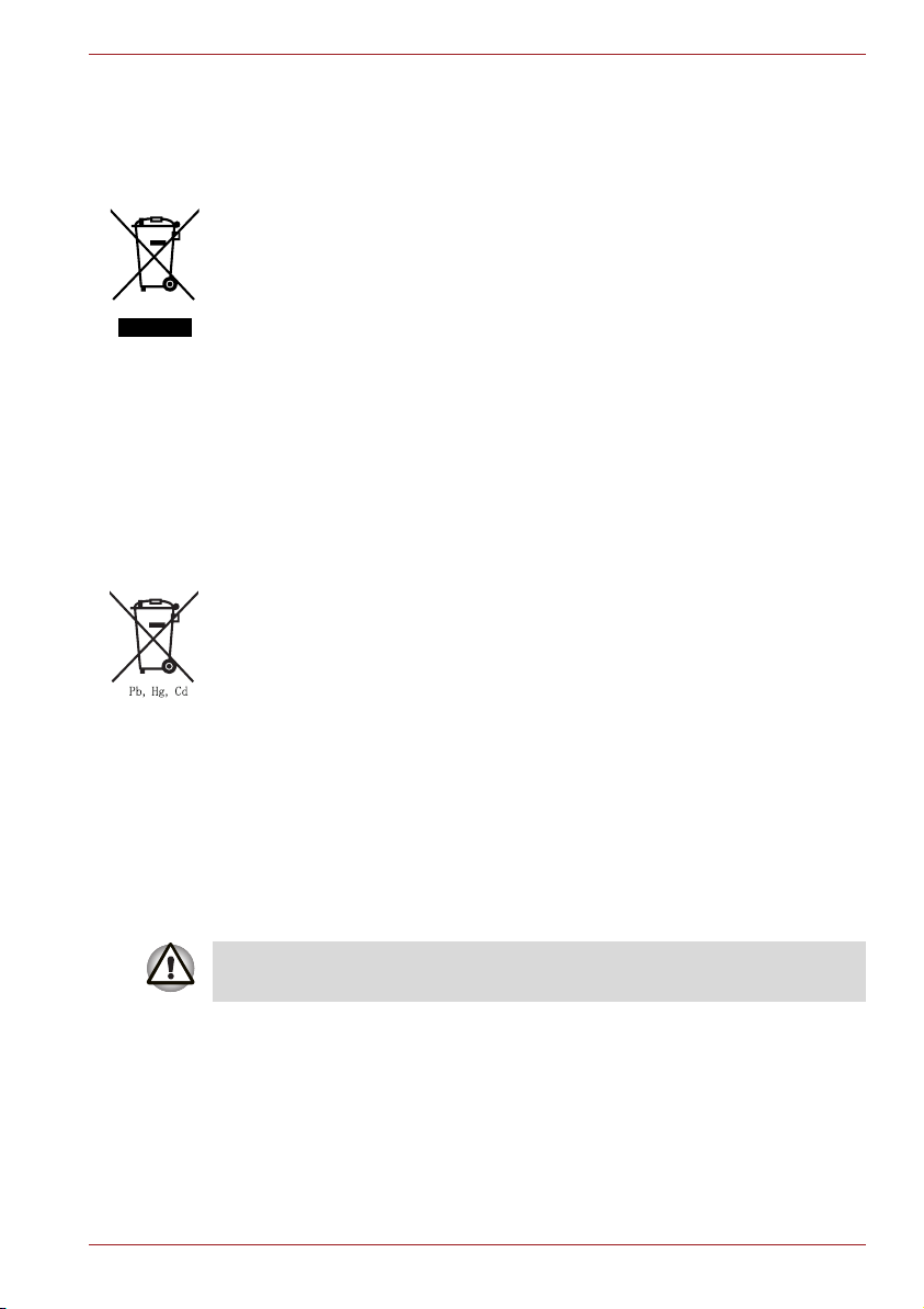
Disposal of products
The crossed out wheeled dust bin symbol indicates that products must be
collected and disposed of separately from household waste. Integrated
batteries and accumulators can be disposed of with the product. They will
be separated at the recycling centres.
The black bar indicates that the product was placed on the market after
August 13, 2005.
By participating in separate collection of products and batteries, you will
help to assure the proper disposal of products and batteries and thus help
to prevent potential negative consequences for the environment and
human health.
For more detailed information about the collection and recycling
programmes available in your country, please visit our website (http://
eu.computers.toshiba-europe.com) or contact your local city office or the
shop where you purchased the product.
Disposal of batteries and/or accumulators
The crossed out wheeled dust bin symbol indicates that batteries and/or
accumulators must be collected and disposed of separately from
household waste.
If the battery or accumulator contains more than the specified values of
lead (Pb), mercury (Hg), and/or cadmium (Cd) defined in the Battery
Directive (2006/66/EC), then the chemical symbols for lead (Pb), mercury
(Hg) and/or cadmium (Cd) will appear below the crossed out wheeled dust
bin symbol.
By participating in separate collection of batteries, you will help to assure
the proper disposal of products and batteries and thus help to prevent
potential negative consequences for the environment and human health.
For more detailed information about the collection and recycling
programmes available in your country, please visit our website (http://
eu.computers.toshiba-europe.com) or contact your local city office or the
shop where you purchased the product.
These symbols may not stick depending on the country and region where
you purchased.
User’s Manual vii
Page 8

ENERGY STAR® Program
Your computer model may be ENERGY STAR®
Compliant. If the model you purchased is compliant, it
is labeled with the ENERGY STAR logo on the
computer and the following information applies.
TOSHIBA. is a partner in the Environmental Protection
Agency's (EPA) ENERGY STAR Program and has
designed this computer to meet the latest ENERGY
ships with the power management options preset to a configuration that will
provide the most stable operating environment and optimum system
performance for both AC power and battery modes.
To conserve energy, your computer is set to enter the low-power Sleep
Mode which shuts down the system and display within 15 minutes of
inactivity in AC power mode. We recommend that you leave this and other
energy saving features active, so that your computer will operate at its
maximum energy efficiency. You can wake the computer from Sleep Mode
by pressing the power button.
According to the EPA, a computer meeting the new ENERGY STAR
specifications will use between 20% and 50% less energy depending on
how it is used. If all U.S. household and businesses replaced old
computers with new ENERGY STAR qualified models, we would save more
than $1.8 billion in energy costs over the next five years and avoid
greenhouse gas emissions equivalent to more than 2.7 million cars.
If every computer purchased by businesses next year met the new
ENERGY STAR requirements, businesses would save more than $210
million over the lifetime of those models. That is equivalent to lighting 120
million square feet of U.S. commercial building space each year.
Visit http://www.energystar.gov or http://www.energystar.gov/power
management for more information regarding the ENERGY STAR Program.
STAR guidelines for energy efficiency. Your computer
viii User’s Manual
Page 9

Important Notice
Copyrighted works including, but not limited to music, video, computer
program, databases are protected by copyright laws. Unless specifically
permitted under applicable copyright laws, you cannot copy, modify, assign,
transmit or otherwise dispose of any copyrighted work with the consent of
the owner of the copyright. Please take notice that unauthorized copying,
modification, assignment, transmission and disposition may be subject to
claims for damages and penalties.
■ Avoid using a telephone (other than a cordless type) during an electrical
storm. There may be a remote risk of electric shock from lightning.
■ Do not use the telephone to report a gas leak in the vicinity of the leak.
■ Use only the power cord indicated in this manual.
■ Replace only with the same or equivalent type battery recommended by
the manufacturer.
■ Dispose of used batteries according to the manufacturer's instructions.
Use only the battery pack that came with the computer or an optional
battery pack. Use of wrong battery could damage your computer.
TOSHIBA assumes no liability for any damage in such case.
User’s Manual ix
Page 10

General Precautions
TOSHIBA computers are designed to optimize safety, minimize strain and
withstand the rigors of portability. However, certain precautions should be
observed to further reduce the risk of personal injury or damage to the
computer.
Be certain to read the general precautions below and to note the cautions
included in the text of the manual.
Provide adequate ventilation
■ Always make sure your computer and AC adaptor have adequate
ventilation and are protected from overheating when the power is
turned on or when an AC adaptor is connected to a power outlet (even if
your computer is in Sleep Mode). In this condition, observe the
following:
■ Never cover your computer or AC adaptor with any object.
■ Never place your computer or AC adaptor near a heat source, such
as anelectric blanket or heater.
■ Never cover or block the air vents including those located at the
base of the computer.
■ Always operate your computer on a hard flat surface. Using your
computer on a carpet or other soft material can block the vents.
■ Always provide sufficient space around the computer.
■ Overheating your computer or AC adaptor could cause system failure,
computer or AC adaptor damage or a fire, possibly resulting in serious
injury.
User’s Manual xi
Page 11

Creating a computer-friendly environment
Place the computer on a flat surface that is large enough for the computer
and any other items you are using, such as a printer.
Leave enough space around the computer and other equipment to provide
adequate ventilation. Otherwise, they may overheat.
To keep your computer in prime operating condition, protect your work area
from:
■ Dust, moisture, and direct sunlight.
■ Equipment that generates a strong electromagnetic field, such as
stereo speakers (other than speakers that are connected to the
computer) or speakerphones.
■ Rapid changes in temperature or humidity and sources of temperature
change such as air conditioner vents or heaters.
■ Extreme heat, cold, or humidity.
■ Liquids and corrosive chemicals.
Stress injury
Carefully read the Instruction Manual for Safety and Comfort. It contains
information on the prevention of stress injuries to your hands and wrists
that can be caused by extensive keyboard use. Instruction Manual for
Safety and Comfort, also includes information on work space design,
posture and lighting that can help reduce physical stress.
Heat injury
■ Avoid prolonged physical contact with the computer. If the computer is
used for long periods, its surface can become very warm. While the
temperature will not feel hot to the touch, if you maintain physical
contact with the computer for a long time, for example if you rest the
computer on your lap or if you keep your hands on the palm rest, your
skin might suffer a low-heat injury.
■ If the computer has been used for a long time, avoid direct contact with
the metal plate supporting the various interface ports as this can
become hot.
■ The surface of the AC adaptor can become hot when in use but this
condition does not indicate a malfunction. If you need to transport the
AC adaptor, you should disconnect it and let it cool before moving it.
■ Do not lay the AC adaptor on a material that is sensitive to heat as the
material could become damaged.
xii User’s Manual
Page 12

Pressure or impact damage
Do not apply heavy pressure to the computer or subject it to any form of
strong impact as this can damage the computer's components or otherwise
cause it to malfunction.
Mobile phones
Please be aware that the use of mobile phones can interfere with the audio
system. The operation of the computer will not be impaired in any way, but
it is recommended that a minimum distance of 30cm is maintained between
the computer and a mobile phone that is in use.
Instruction Manual for Safety and Comfort
All important information on the safe and proper use of this computer is
described in the enclosed Instruction Manual for Safety and Comfort. Be
sure to read it before using the computer.
User’s Manual xiii
Page 13

Table of Contents
Preface
Manual contents . . . . . . . . . . . . . . . . . . . . . . . . . . . . . . . . . . . . . . . . . . -xxi
Conventions . . . . . . . . . . . . . . . . . . . . . . . . . . . . . . . . . . . . . . . . . . . . -xxii
Abbreviations . . . . . . . . . . . . . . . . . . . . . . . . . . . . . . . . . . . . . . . . . . -xxii
Icons . . . . . . . . . . . . . . . . . . . . . . . . . . . . . . . . . . . . . . . . . . . . . . . . .-xxii
Keys . . . . . . . . . . . . . . . . . . . . . . . . . . . . . . . . . . . . . . . . . . . . . . . . .-xxii
Key operation . . . . . . . . . . . . . . . . . . . . . . . . . . . . . . . . . . . . . . . . . -xxiii
Display . . . . . . . . . . . . . . . . . . . . . . . . . . . . . . . . . . . . . . . . . . . . . . -xxiii
Messages . . . . . . . . . . . . . . . . . . . . . . . . . . . . . . . . . . . . . . . . . . . . -xxiii
Chapter 1 Introduction
Equipment checklist. . . . . . . . . . . . . . . . . . . . . . . . . . . . . . . . . . . . . . . 1-1
Hardware . . . . . . . . . . . . . . . . . . . . . . . . . . . . . . . . . . . . . . . . . . . . . 1-1
Software . . . . . . . . . . . . . . . . . . . . . . . . . . . . . . . . . . . . . . . . . . . . . . 1-2
Features. . . . . . . . . . . . . . . . . . . . . . . . . . . . . . . . . . . . . . . . . . . . . . . . . 1-3
Special features . . . . . . . . . . . . . . . . . . . . . . . . . . . . . . . . . . . . . . . . . . 1-9
TOSHIBA Value Added Package . . . . . . . . . . . . . . . . . . . . . . . . . . . . 1-11
Utilities and Applications. . . . . . . . . . . . . . . . . . . . . . . . . . . . . . . . . . 1-12
Options . . . . . . . . . . . . . . . . . . . . . . . . . . . . . . . . . . . . . . . . . . . . . . . . 1-14
Chapter 2 The Grand Tour
Front with the display closed . . . . . . . . . . . . . . . . . . . . . . . . . . . . . . . 2-1
Left side. . . . . . . . . . . . . . . . . . . . . . . . . . . . . . . . . . . . . . . . . . . . . . . . . 2-3
Right side . . . . . . . . . . . . . . . . . . . . . . . . . . . . . . . . . . . . . . . . . . . . . . . 2-5
Backside . . . . . . . . . . . . . . . . . . . . . . . . . . . . . . . . . . . . . . . . . . . . . . . . 2-7
Underside . . . . . . . . . . . . . . . . . . . . . . . . . . . . . . . . . . . . . . . . . . . . . . . 2-7
Front with the display open. . . . . . . . . . . . . . . . . . . . . . . . . . . . . . . . . 2-9
AC adaptor . . . . . . . . . . . . . . . . . . . . . . . . . . . . . . . . . . . . . . . . . . . . . 2-12
User’s Manual xv
Page 14

Chapter 3 Getting Started
Connecting the AC adaptor. . . . . . . . . . . . . . . . . . . . . . . . . . . . . . . . . .3-2
Opening the display. . . . . . . . . . . . . . . . . . . . . . . . . . . . . . . . . . . . . . . .3-4
Turning on the power. . . . . . . . . . . . . . . . . . . . . . . . . . . . . . . . . . . . . . .3-5
Windows® 7 setup . . . . . . . . . . . . . . . . . . . . . . . . . . . . . . . . . . . . . . . . .3-6
Turning off the power. . . . . . . . . . . . . . . . . . . . . . . . . . . . . . . . . . . . . . .3-7
Shut Down mode (Boot mode) . . . . . . . . . . . . . . . . . . . . . . . . . . . . . .3-7
Sleep Mode . . . . . . . . . . . . . . . . . . . . . . . . . . . . . . . . . . . . . . . . . . . .3-7
Hibernation Mode . . . . . . . . . . . . . . . . . . . . . . . . . . . . . . . . . . . . . . . .3-9
Restarting the computer . . . . . . . . . . . . . . . . . . . . . . . . . . . . . . . . . . .3-10
System Recovery Options. . . . . . . . . . . . . . . . . . . . . . . . . . . . . . . . . .3-11
System Recovery Options . . . . . . . . . . . . . . . . . . . . . . . . . . . . . . . .3-11
Create Optical Recovery Media. . . . . . . . . . . . . . . . . . . . . . . . . . . . . .3-12
Restoring the preinstalled software from the Recovery HDD . . . . .3-13
Restoring the preinstalled software from Recovery Media . . . . . . .3-14
Chapter 4 Operating Basics
Using the Touch Pad . . . . . . . . . . . . . . . . . . . . . . . . . . . . . . . . . . . . . . .4-1
Using the Web Camera . . . . . . . . . . . . . . . . . . . . . . . . . . . . . . . . . . . . .4-2
Using the software . . . . . . . . . . . . . . . . . . . . . . . . . . . . . . . . . . . . . . .4-3
Using the TOSHIBA Face Recognition. . . . . . . . . . . . . . . . . . . . . . . . .4-4
Note on Use . . . . . . . . . . . . . . . . . . . . . . . . . . . . . . . . . . . . . . . . . . . .4-4
Disclaimer. . . . . . . . . . . . . . . . . . . . . . . . . . . . . . . . . . . . . . . . . . . . . .4-4
How to register the Face Recognition Data . . . . . . . . . . . . . . . . . . . .4-4
How to Delete the Face Recognition Data . . . . . . . . . . . . . . . . . . . . .4-5
How to launch the help file . . . . . . . . . . . . . . . . . . . . . . . . . . . . . . . . .4-6
Windows Logon via TOSHIBA Face Recognition. . . . . . . . . . . . . . . .4-6
Using the microphone . . . . . . . . . . . . . . . . . . . . . . . . . . . . . . . . . . . . . .4-7
TOSHIBA Disc Creator. . . . . . . . . . . . . . . . . . . . . . . . . . . . . . . . . . . . . .4-7
Wireless communications . . . . . . . . . . . . . . . . . . . . . . . . . . . . . . . . . . .4-8
Wireless LAN . . . . . . . . . . . . . . . . . . . . . . . . . . . . . . . . . . . . . . . . . . .4-9
Security. . . . . . . . . . . . . . . . . . . . . . . . . . . . . . . . . . . . . . . . . . . . . . .4-10
Bluetooth Stack for Windows by TOSHIBA . . . . . . . . . . . . . . . . . . .4-10
Enable/Disable Wireless communication with hot key . . . . . . . . . . .4-10
Wireless activity LED . . . . . . . . . . . . . . . . . . . . . . . . . . . . . . . . . . . .4-11
LAN . . . . . . . . . . . . . . . . . . . . . . . . . . . . . . . . . . . . . . . . . . . . . . . . . . . .4-11
LAN cable types . . . . . . . . . . . . . . . . . . . . . . . . . . . . . . . . . . . . . . . .4-11
Connecting LAN cable . . . . . . . . . . . . . . . . . . . . . . . . . . . . . . . . . . .4-12
Disconnecting LAN cable . . . . . . . . . . . . . . . . . . . . . . . . . . . . . . . . .4-12
USB Sleep and Charge function . . . . . . . . . . . . . . . . . . . . . . . . . . . . .4-12
Starting the USB Sleep and Charge Utility . . . . . . . . . . . . . . . . . . . .4-13
Enabling USB Sleep and Charge . . . . . . . . . . . . . . . . . . . . . . . . . . .4-13
Power supply mode settings. . . . . . . . . . . . . . . . . . . . . . . . . . . . . . .4-14
Battery Settings . . . . . . . . . . . . . . . . . . . . . . . . . . . . . . . . . . . . . . . .4-14
xvi User’s Manual
Page 15

Cleaning the computer. . . . . . . . . . . . . . . . . . . . . . . . . . . . . . . . . . . . 4-14
Moving the computer . . . . . . . . . . . . . . . . . . . . . . . . . . . . . . . . . . . . . 4-15
Using the Hard Disk Drive (HDD) Protection . . . . . . . . . . . . . . . . . . 4-15
TOSHIBA HDD Protection Properties. . . . . . . . . . . . . . . . . . . . . . . 4-16
Details. . . . . . . . . . . . . . . . . . . . . . . . . . . . . . . . . . . . . . . . . . . . . . . 4-17
Chapter 5 The Keyboard
Typewriter keys. . . . . . . . . . . . . . . . . . . . . . . . . . . . . . . . . . . . . . . . . . . 5-1
F1 ... F12 function keys . . . . . . . . . . . . . . . . . . . . . . . . . . . . . . . . . . . . 5-2
Soft keys: FN key combinations . . . . . . . . . . . . . . . . . . . . . . . . . . . . . 5-2
Emulating keys on enhanced keyboard . . . . . . . . . . . . . . . . . . . . . . 5-2
Hot keys. . . . . . . . . . . . . . . . . . . . . . . . . . . . . . . . . . . . . . . . . . . . . . . . . 5-3
FN Sticky key (Depends on the model you purchased) . . . . . . . . . . 5-5
Windows® special keys. . . . . . . . . . . . . . . . . . . . . . . . . . . . . . . . . . . . 5-5
Keypad overlay . . . . . . . . . . . . . . . . . . . . . . . . . . . . . . . . . . . . . . . . . . . 5-6
Turning on the overlays. . . . . . . . . . . . . . . . . . . . . . . . . . . . . . . . . . . 5-6
Temporarily using normal keyboard (overlay on) . . . . . . . . . . . . . . . 5-7
Temporarily using overlay (overlay off) . . . . . . . . . . . . . . . . . . . . . . . 5-7
Temporarily changing modes . . . . . . . . . . . . . . . . . . . . . . . . . . . . . . 5-7
Generating ASCII characters. . . . . . . . . . . . . . . . . . . . . . . . . . . . . . . . 5-7
Chapter 6 Power and Power-Up Modes
Power conditions . . . . . . . . . . . . . . . . . . . . . . . . . . . . . . . . . . . . . . . . . 6-1
Power indicators. . . . . . . . . . . . . . . . . . . . . . . . . . . . . . . . . . . . . . . . . . 6-2
Battery indicator . . . . . . . . . . . . . . . . . . . . . . . . . . . . . . . . . . . . . . . . 6-2
Power indicator . . . . . . . . . . . . . . . . . . . . . . . . . . . . . . . . . . . . . . . . . 6-3
Battery types. . . . . . . . . . . . . . . . . . . . . . . . . . . . . . . . . . . . . . . . . . . . . 6-3
Battery pack . . . . . . . . . . . . . . . . . . . . . . . . . . . . . . . . . . . . . . . . . . . 6-3
Real Time Clock battery . . . . . . . . . . . . . . . . . . . . . . . . . . . . . . . . . . 6-4
Care and use of the battery pack . . . . . . . . . . . . . . . . . . . . . . . . . . . . 6-6
Safety precautions . . . . . . . . . . . . . . . . . . . . . . . . . . . . . . . . . . . . . . 6-6
Charging the batteries. . . . . . . . . . . . . . . . . . . . . . . . . . . . . . . . . . . . 6-8
Monitoring battery capacity. . . . . . . . . . . . . . . . . . . . . . . . . . . . . . . 6-10
Maximizing battery operating time . . . . . . . . . . . . . . . . . . . . . . . . . 6-10
Retaining data with power off . . . . . . . . . . . . . . . . . . . . . . . . . . . . . .6-11
Extending battery life . . . . . . . . . . . . . . . . . . . . . . . . . . . . . . . . . . . .6-11
Replacing the battery pack . . . . . . . . . . . . . . . . . . . . . . . . . . . . . . . . 6-12
Removing the battery pack . . . . . . . . . . . . . . . . . . . . . . . . . . . . . . . 6-13
Installing the battery pack . . . . . . . . . . . . . . . . . . . . . . . . . . . . . . . . 6-14
Starting the computer by password . . . . . . . . . . . . . . . . . . . . . . . . . 6-14
Power-up modes. . . . . . . . . . . . . . . . . . . . . . . . . . . . . . . . . . . . . . . . . 6-15
Hot keys . . . . . . . . . . . . . . . . . . . . . . . . . . . . . . . . . . . . . . . . . . . . . 6-15
Panel power off/on . . . . . . . . . . . . . . . . . . . . . . . . . . . . . . . . . . . . . . . 6-15
System Auto Off . . . . . . . . . . . . . . . . . . . . . . . . . . . . . . . . . . . . . . . . . 6-15
User’s Manual xvii
Page 16

Chapter 7 HW Setup
Accessing HW Setup . . . . . . . . . . . . . . . . . . . . . . . . . . . . . . . . . . . . . . .7-1
HW Setup Window . . . . . . . . . . . . . . . . . . . . . . . . . . . . . . . . . . . . . . . . .7-1
Chapter 8 Optional Devices
Bridge media slot . . . . . . . . . . . . . . . . . . . . . . . . . . . . . . . . . . . . . . . . . .8-2
Installing a memory card. . . . . . . . . . . . . . . . . . . . . . . . . . . . . . . . . . .8-3
Removing a memory card . . . . . . . . . . . . . . . . . . . . . . . . . . . . . . . . .8-4
Memory card care. . . . . . . . . . . . . . . . . . . . . . . . . . . . . . . . . . . . . . . .8-5
Memory expansion. . . . . . . . . . . . . . . . . . . . . . . . . . . . . . . . . . . . . . . . .8-6
Installing a memory module . . . . . . . . . . . . . . . . . . . . . . . . . . . . . . . .8-6
Removing a memory module . . . . . . . . . . . . . . . . . . . . . . . . . . . . . . .8-8
Additional battery pack . . . . . . . . . . . . . . . . . . . . . . . . . . . . . . . . . . . . .8-9
Additional AC adaptor . . . . . . . . . . . . . . . . . . . . . . . . . . . . . . . . . . . . . .8-9
External monitor. . . . . . . . . . . . . . . . . . . . . . . . . . . . . . . . . . . . . . . . . .8-10
Security lock. . . . . . . . . . . . . . . . . . . . . . . . . . . . . . . . . . . . . . . . . . . . .8-10
Chapter 9 Troubleshooting
Problem solving process. . . . . . . . . . . . . . . . . . . . . . . . . . . . . . . . . . . .9-1
Preliminary checklist. . . . . . . . . . . . . . . . . . . . . . . . . . . . . . . . . . . . . .9-2
Analyzing the problem . . . . . . . . . . . . . . . . . . . . . . . . . . . . . . . . . . . .9-2
Hardware and system checklist . . . . . . . . . . . . . . . . . . . . . . . . . . . . . .9-3
System start-up. . . . . . . . . . . . . . . . . . . . . . . . . . . . . . . . . . . . . . . . . .9-3
Self test. . . . . . . . . . . . . . . . . . . . . . . . . . . . . . . . . . . . . . . . . . . . . . . .9-4
Power . . . . . . . . . . . . . . . . . . . . . . . . . . . . . . . . . . . . . . . . . . . . . . . . .9-4
Disposing of PC and PC batteries . . . . . . . . . . . . . . . . . . . . . . . . . . .9-6
Real Time Clock . . . . . . . . . . . . . . . . . . . . . . . . . . . . . . . . . . . . . . . . .9-7
Keyboard . . . . . . . . . . . . . . . . . . . . . . . . . . . . . . . . . . . . . . . . . . . . . .9-7
LCD panel. . . . . . . . . . . . . . . . . . . . . . . . . . . . . . . . . . . . . . . . . . . . . .9-8
Hard disk drive . . . . . . . . . . . . . . . . . . . . . . . . . . . . . . . . . . . . . . . . . .9-9
Recovery Media . . . . . . . . . . . . . . . . . . . . . . . . . . . . . . . . . . . . . . . . .9-9
Pointing device . . . . . . . . . . . . . . . . . . . . . . . . . . . . . . . . . . . . . . . . .9-10
USB . . . . . . . . . . . . . . . . . . . . . . . . . . . . . . . . . . . . . . . . . . . . . . . . .9-11
USB Sleep and Charge function. . . . . . . . . . . . . . . . . . . . . . . . . . . .9-12
Memory expansion . . . . . . . . . . . . . . . . . . . . . . . . . . . . . . . . . . . . . .9-13
Sound system. . . . . . . . . . . . . . . . . . . . . . . . . . . . . . . . . . . . . . . . . .9-14
Monitor . . . . . . . . . . . . . . . . . . . . . . . . . . . . . . . . . . . . . . . . . . . . . . .9-14
LAN. . . . . . . . . . . . . . . . . . . . . . . . . . . . . . . . . . . . . . . . . . . . . . . . . .9-14
Wireless LAN . . . . . . . . . . . . . . . . . . . . . . . . . . . . . . . . . . . . . . . . . .9-14
Bluetooth . . . . . . . . . . . . . . . . . . . . . . . . . . . . . . . . . . . . . . . . . . . . .9-15
SD/MuliMedia Card . . . . . . . . . . . . . . . . . . . . . . . . . . . . . . . . . . . . .9-15
Using Windows® XP Mode on your Windows® 7 computer (available on
certain models) . . . . . . . . . . . . . . . . . . . . . . . . . . . . . . . . . . . . . . . . .9-15
TOSHIBA support. . . . . . . . . . . . . . . . . . . . . . . . . . . . . . . . . . . . . . . . .9-16
xviii User’s Manual
Page 17

Before you call . . . . . . . . . . . . . . . . . . . . . . . . . . . . . . . . . . . . . . . . 9-16
Where to write. . . . . . . . . . . . . . . . . . . . . . . . . . . . . . . . . . . . . . . . . 9-16
Appendix A Specifications
Appendix B Display Controller
Appendix C Wireless LAN
Appendix D AC Power Cord and Connectors
Appendix E TOSHIBA PC Health Monitor
Starting the TOSHIBA PC Health Monitor. . . . . . . . . . . . . . . . . . . . . . E-2
If a TOSHIBA PC Health Monitor message is displayed . . . . . . . . . . E-2
Appendix F Legal Footnotes
Glossary
Index
User’s Manual xix
Page 18

Preface
Congratulations on your purchase of the TOSHIBA Satellite T130/T110,
Satellite Pro T130/T110, PORTEGE T130/T110 Series computer. This
powerful notebook computer provides excellent expansion capability,
including multimedia devices, and it is designed to provide years of reliable,
high-performance computing.
This manual tells you how to set up and begin using your TOSHIBA
Satellite T130/T110, Satellite Pro T130/T110, PORTEGE T130/T110 Series
computer. It also provides detailed information on configuring your
computer, basic operations and care, using optional devices and
troubleshooting.
If you are a new user of computers or if you're new to portable computing,
first read over the Introduction and The Grand Tour chapters to familiarize
yourself with the computer's features, components and accessory devices.
Then read Getting Started for step-by-step instructions on setting up your
computer.
If you are an experienced computer user, please continue reading the
preface to learn how this manual is organized, then become acquainted
with this manual by browsing through its pages. Be sure to look over the
Specifications section of the Introduction, to learn about features that are
uncommon or unique to the computer. If you are going to install Memory
cards or connect external devices such as a monitor, be sure to read
Chapter 8, Optional Devices.
Manual contents
This manual is composed of the following nine chapters, five appendixes, a
glossary and an index.
Chapter 1, Introduction, is an overview of the computer's features,
capabilities, and options.
Chapter 2, The Grand Tour, identifies the components of the computer and
briefly explains how they function.
Chapter 3, Getting Started, provides a quick overview of how to begin
operating your computer and gives tips on safety and designing your work
area.
User’s Manual xxi
Page 19

Preface
Chapter 4, Operating Basics, includes instructions on using the following
devices: Touch Pad, Sound System, wireless communication and LAN. It
also provides tips on care of the computer, and CD/DVDs.
Chapter 5, The Keyboard, describes special keyboard functions including
the keypad overlay and hot keys.
Chapter 6, Power and Power-Up Modes, gives details on the computer's
power resources and battery save modes.
Chapter 7, HW Setup explains how to configure the computer using the
HW Setup program.
Chapter 8, Optional Devices, describes the optional hardware available.
Chapter 9, Troubleshooting, provides helpful information on how to perform
some diagnostic tests, and suggests courses of action if the computer
doesn't seem to be working properly.
The Appendices provide technical information about your computer.
The Glossary defines general computer terminology and includes a list of
acronyms used in the text.
The Index quickly directs you to the information contained in this manual.
Conventions
This manual uses the following formats to describe, identify, and highlight
terms and operating procedures.
Abbreviations
On first appearance, and whenever necessary for clarity, abbreviations are
enclosed in parenthesis following their definition. For example: Read Only
Memory (ROM). Acronyms are also defined in the Glossary.
Icons
Icons identify ports, dials, and other parts of your computer. The indicator
panel also uses icons to identify the components it is providing information
on.
Keys
The keyboard keys are used in the text to describe many computer
operations. A distinctive typeface identifies the key top symbols as they
appear on the keyboard. For example, Enter identifies the ENTER key.
xxii User’s Manual
Page 20
Key operation
Some operations require you to simultaneously use two or more keys. We
identify such operations by the key top symbols separated by a plus sign
(+). For example, CTRL + C means you must hold down CTRL and at the
same time press C. If three keys are used, hold down the first two and at
the same time press the third.
Preface
ABC When procedures require an action such as
clicking an icon or entering text, the icon's name
or the text you are to type in is represented in the
type face you see to the left.
Display
ABC
Names of windows or icons or text generated by
the computer that appears on its display screen
is presented in the type face you see to the left.
Messages
Messages are used in this manual to bring important information to your
attention. Each type of message is identified as shown below.
Pay attention! A caution informs you that improper use of equipment or
failure to follow instructions may cause data loss or damage your
equipment.
Please read. A note is a hint or advice that helps you make best use of
your equipment.
Indicates a potentially hazardous situation, which could result in death or
serious injury, if you do not follow instructions.
Terminology
This term is defined in this document as follows:
Start
User’s Manual xxiii
The word “Start” refers to the “ ” button in
Windows
®
7.
Page 21
Chapter 1
Introduction
This chapter provides an equipment checklist, and it identifies the
computer's features, options and accessories.
Some of the features described in this manual may not function properly if
you use an operating system that was not pre-installed by TOSHIBA.
Equipment checklist
Carefully unpack your computer. Save the box and packing materials for
future use.
Hardware
Check to make sure you have all the following items:
■ TOSHIBA Satellite T130/T110, Satellite Pro T130/T110, PORTEGE
T130/T110 Series Portable Personal Computer
■ Universal AC adaptor and power cord (2-pin plug or 3-pin plug)
■ Battery pack (installed in the computer)
User’s Manual 1-1
Page 22

Introduction
Software
Windows® 7
The following software is preinstalled:
®
■ Windows
■ Microsoft Internet Explorer
■ TOSHIBA Value Added Package
■ TOSHIBA Hardware Setup
■ TOSHIBA Supervisor Password
■ TOSHIBA Assist
■ TOSHIBA ConfigFree™
■ TOSHIBA SD Memory Utilites
■ TOSHIBA Disc Creator
■ TOSHIBA eco Utility
■ Online Manual (This manual)
Other software may be preinstalled dependant on the model purchased.
7
Documentation
■ Satellite T130/T110, Satellite Pro T130/T110, PORTEGE T130/T110
Series Personal Computer User Information Guide
■ Instruction Manual for Safety and Comfort
If any of the items are missing or damaged, contact your dealer
immediately.
1-2 User’s Manual
Page 23

Features
Introduction
This section describes the hardware of your computer.
The actual specifications may vary depending on the model you
purchased.
Processor
CPU Your computer is equipped with one processor
and processor type varies depending on model.
To check which type of processor is included in
your model, open the TOSHIBA PC Diagnostic
Tool Utility by clicking Start Æ All Programs Æ
TOSHIBA Æ Utilities Æ PC Diagnostic Tool.
Legal Footnote (CPU)*2
For more information on the CPU, please refer to the Legal Footnotes
section in Appendix F or click the *2 above.
Chipset
Mobile Intel® GS45/GS40 Express Chipset
Memory
Slots 1, 2 or 4GB* memory modules can be installed in
the computer's two memory slots.
The actual amount of useable system memory
will be less than the installed memory modules.
Maximum system memory size:
8GB(4GBx2) for GS45 chipset models.
4GB(2GBx2) for GS40 chipset models.
* 4GB memory modules cannot be installed in
GS40 chipset models.
Please visit your region's web site or refer to the catalog for the
configuration details of the model that you have purchased.
User’s Manual 1-3
Page 24

Introduction
Main Memory
Disclaimer
Video RAM Video RAM capacity shares with main memory,
Part of the main system memory may be used by
the graphics system for graphics performance
and therefore reduce the amount of main system
memory available for other computing activities.
The amount of main system memory allocated to
support graphics may vary depending on the
graphics system, applications utilized, system
memory size and other factors. Computers
configured with a 32-bit operating system can
address up to 3GB of system memory. Only
computers configured with a 64-bit operating
system can address 4GB or more of system
memory.
and the proportion depends on Dynamic Video
Memory Technology.
Legal Footnote (Memory (Main System))*3
For more information regarding Memory (Main System), please refer to the
Legal Footnotes section in Appendix F or click the *3 above.
Power
Battery Pack Your computer is powered by a rechargeable
lithium-ion battery pack.
Legal Footnote (Battery Life)*4
For more information regarding Battery Life, please refer to the Legal
Footnotes section in Appendix F or click the *4 above.
RTC Battery The internal RTC battery backs up the Real Time
AC Adaptor The AC adaptor provides power to the system
1-4 User’s Manual
Clock(RTC) and calendar.
and recharges the batteries when they are low. It
comes with a detachable power cord which will
either have a 2-pin or 3-pin plug enclosure.
As the AC adaptor is universal, it can receive a
range of AC voltages from 100 to 240 volts,
however you should note that the output current
varies among different models. Using the wrong
adaptor can damage your computer. Refer to the
AC adaptor section in Chapter 2, The Grand
Tour.
Page 25

Disks
Introduction
Hard disk Disclaimer
Hard disk Drive This computer is equipped with one of the
1 Gigabyte (GB) means 10
bytes using powers of 10. The computer
operating system, however, reports storage
capacity using powers of 2 for the definition of 1
30
GB = 2
shows less storage capacity. Available storage
capacity will also be less if the product includes
one or more pre-installed operating systems,
such as Microsoft Operating System and/or preinstalled software applications, or media content.
Actual formatted capacity may vary.
following hard disk drive (HDD) types. The
capacity of each hard disk drive model is
different.
■ 250GB
■ 320GB
■ 400GB
■ 500GB
Please note that part of the hard disk drives
overall capacity is reserved as administration
space. Additional Hard Disk drive sizes may be
introduced.
= 1,073,741,824 bytes, and therefore
9
= 1,000,000,000
Legal Footnote (Hard Disk Drive (HDD) Capacity)*5
For more information regarding Hard Disk Drive (HDD) Capacity, please
refer to the Legal Footnotes section in Appendix F or click the *5 above.
Display
The computer's LCD panel supports high-resolution video graphics. The
screen can be set at a wide range of viewing angles for maximum comfort
and readability.
Built-In 13.3" or 11.6" WXGA 16 M colors, with the
following resolution:
1366 horizontal × 768 vertical pixels.
Legal Footnote (LCD)*6
For more information regarding the LCD, please refer to the Legal
Footnotes section in Appendix F or click the *6 above.
User’s Manual 1-5
Page 26

Introduction
Graphics Controller Graphics controller maximizes display
performance. Refer to Display Controller section
in Appendix B, Display Controller for more
information.
Legal Footnote (Graphics Processor Unit ("GPU"))*7
For more information regarding the Graphics Processor Unit ("GPU"),
please refer to the Legal Footnotes section in Appendix F or click the *7
above.
Keyboard
Built-In The internal keyboard provides the embedded
numeric overlay keys, dedicated cursor control
overlay keys, and and Keys.
®
The keyboard is compatible with the IBM
enhanced keyboard. Refer to Chapter 5, The
Keyboard, for details.
Pointing Device
Built-In Touch Pad A Touch Pad and control buttons in the palm rest
enable control of the on-screen pointer and
scrolling of windows.
Ports
HDMI out port This HDMI out port allows you to connect
External Monitor This 15-pin port lets you connect an external
Universal Serial Bus
(USB 2.0)
1-6 User’s Manual
external display/audio devices. (Provided with
some models)
video display.
The computer supports multiple Universal Serial
Bus ports that comply with the USB 2.0 standard.
The port with the ( ) has a USB Sleep and
Charge function.
Page 27

Introduction
Slots
Bridge Media Slot This slot lets you insert an SD™/SDHC™
memory card, Memory Stick™(PRO™/PRO
Duo™ ), xD-Picture Card™, and
MultiMediaCard™.
Multimedia
Web Camera Record/Send still or video images with this
Sound System The integrated sound system provides support
Headphone jack A 3.5 mm mini headphone jack enables
Microphone Jack A 3.5 mm mini microphone jack enables
integrated Web Camera.
for the computer's internal speakers and
microphone, as allowing an external microphone
and headphones to be connected via the
appropriate jacks.
connection of stereo headphones.
connection of a three-conductor mini jack for
monaural microphone input.
Communications
LAN The computer has built-in support for Ethernet
LAN (10 megabits per second, 10BASE-T) and
Fast Ethernet LAN (100 megabits per second,
100BASE-TX).
Wireless LAN The Wireless LAN feature is not available on all
models. Where present, it supports the b,g
standards and n* draft2.0 but it is compatible with
other LAN systems based on Direct Sequence
Spread Spectrum / Orthogonal Frequency
Division Multiplexing radio technology that
complies with the IEEE 802.11 Standard.
* Depends on the installed Wireless LAN module.
■ Roaming over multiple channels
■ Card Power Management
■ Wired Equivalent Privacy (WEP) data
encryption, based on 128 bit encryption
algorithm.
■ Advanced Encryption Standard (AES) data
encryption, based on 256 bit encryption
algorithm.
User’s Manual 1-7
Page 28

Introduction
■ The transmission speed over the wireless LAN, and the distance over
which the wireless LAN can reach, may vary depending on surrounding
electromagnetic environment, obstacles, access point design and
configuration, client design and software/hardware configurations. The
transmission rate described is the theoretical maximum speed as
specified under the appropriate standard - the actual transmission
speed will be lower than the theoretical maximum speed.
■ To enable or disable wireless communication, use the Hot Key FN+F8.
For more information see the Hot keys section in Chapter 5.
Legal Footnote (Wireless LAN)*8
For more information regarding Wireless LAN, please refer to the Legal
Footnotes section in Appendix F or click the *8 above.
Bluetooth Some models are equipped with Bluetooth
wireless communication function which
eliminates the need for cables between
electronic devices such as computers and
printers and mobile phones. When it is enabled,
Bluetooth provides the wireless personal area
network environment which is safe and
trustworthy, that is quick and easy.
Security
Security lock slot Connects an optional security lock to anchor the
computer to a desk or other large object.
Password Power-on password protection
Two level password architecture
HDD password protection
1-8 User’s Manual
Page 29

Special features
The following features are either unique to TOSHIBA computers or are
advanced features, which make the computer more convenient to use.
Introduction
Hot Keys Key combinations let you quickly modify the
system configuration directly from the keyboard
without running a system configuration program.
Keypad Overlay A ten-key pad is integrated into the keyboard.
Refer to the Keypad overlay section in Chapter 5,
The Keyboard, for instructions on using the
keypad overlay.
Instant Security A specific hot key function automatically locks
the system providing data security.
Display Automatic
Power Off
*1
This feature automatically cuts off power to the
internal display when there is no keyboard input
for a specified time. Power is restored when any
key is pressed.
This can be specified in the Power Options.
HDD Automatic
Power Off
*1
This feature automatically cuts off power to the
hard disc drive when it is not accessed for a
specified time. Power is restored when the hard
disc is accessed.
This can be specified in the Power Options.
System Automatic
Sleep Mode/
Hibernation
*1
This feature automatically shuts down the system
into Sleep Mode or Hibernation Mode when there
is no input or hardware access for a specified
time.
This can be specified in the Power Options.
Intelligent Power
Supply
*1
A microprocessor in the computer's intelligent
power supply detects the battery's charge and
calculates the remaining battery capacity. It also
protects electronic components from abnormal
conditions, such as voltage overload from an
AC adaptor.
This can be specified in the Power Options.
*1
Battery Save Mode
This feature lets you configure the computer in
order to save battery power. This can be
specified in the Power Options.
*1
Panel Power On/Off
This feature turns power to the computer off
when the display panel is closed and turns it back
on when the panel is opened.
This can be specified in the Power Options.
User’s Manual 1-9
Page 30

Introduction
Low Battery
Automatic
Hibernation
*1
When battery power is exhausted to the point
that computer operation cannot be continued, the
system automatically enters Hibernation Mode
and shuts down.
This can be specified in the Power Options.
TOSHIBA HDD
Protection
This feature uses the acceleration sensor built in
the computer to detect vibration, falls and
shocks, and automatically moves the hard disk
drive's read/write head to a safe position in order
to reduce the risk of damage that could be
caused by head-to-disk contact. Refer to the
Using the Hard Disk Drive (HDD) Protection
section in Chapter 4, Operating Basics, for more
details.
The TOSHIBA HDD Protection function does not guarantee that the hard
disk drive will not be damaged.
Hibernation Mode This feature lets you turn off the power without
exiting from your software. The contents of main
memory are saved to the hard disk so that when
you turn on the power again, you can continue
working right where you left off. Refer to the
Turning off the power section in Chapter 3,
Getting Started, for details.
Sleep Mode If you have to interrupt your work, you can turn
off the power without exiting from your software.
Data is maintained in the computer's main
memory so that when you turn on the power
again, you can continue working right where you
left off.
*1 Click , Control Panel, System and Security, and then click Power
Options.
1-10 User’s Manual
Page 31

TOSHIBA Value Added Package
This section describes the TOSHIBA Component features pre-installed on
the computer.
Introduction
TOSHIBA Power
Saver
TOSHIBA Zooming
Utility
TOSHIBA PC
Diagnostic Tool
TOSHIBA Flash
Cards
TOSHIBA
Components
Common Driver
TOSHIBA
Accessibility
TOSHIBA Power Saver provides you with the
features of more various power supply
managements.
This utility allows you to enlarge or reduce the
icon size on the Windows Desktop, or the zoom
factor associated with specific supported
applications.
The TOSHIBA PC Diagnostic Tool will display
basic system configuration information and allow
the functionality of some of the computer's builtin hardware devices to be tested.
This utility supports the following functions.
■ Hot key function
■ TOSHIBA utility launcher function
TOSHIBA Components Common Driver contains
the module required for the utility which
TOSHIBA offers.
The TOSHIBA Accessibility utility provides
support to movement impaired users when they
need to use the TOSHIBA Hot-key functions. In
use, the utility allows you to make the FN key
'sticky', that is you can press it once, release it,
and then press one of the 'F' keys in order to
access its specific function. When set, the FN
key will remain active until another key is
pressed.
User’s Manual 1-11
Page 32

Introduction
Utilities and Applications
This section describes pre-installed utilities and tells how to start them. For
details on operations, refer to each utility's online manual, help files or
readme.txt files.
TOSHIBA Assist TOSHIBA Assist is a graphical user interface that
provides easy access to help and services.
HW Setup This program lets you customize your hardware
Power On Password Two levels of password security, supervisor and
TOSHIBA Disc
Creator
TOSHIBA ConfigFree ConfigFree is a suite of utilities to allow easy
settings according to the way you work with your
computer and the peripherals you use. To start
the utility, double click the TOSHIBA Assist on
your desktop, select OPTIMIZE tab, and click
TOSHIBA Hardware Settings.
user, are available to prevent unauthorized
access to your computer.
To register a supervisor password, double click
the TOSHIBA Assist on your desktop select the
SECURE tab and start the Supervisor
password utility.
To set a user password, select the SECURE tab
on TOSHIBA Assist, then start the User
password utility. On the Password tab you can
register a user password.
You can create CD/DVDs in several formats
including audio CDs that can be played on a
standard stereo CD player and data CDs or
DVDs to store multimedia and/or document files
on your hard disk drive. This software can be
used on a model with the CD-RW/DVD-ROM
drive, DVD-R/-RW drive, DVD+_R/+_RW drive
and DVD Super Multi drive.
To run TOSHIBA Disc Creator, click , select
All Programs, TOSHIBA, CD&DVD
Applications, and then click Disc Creator.
control of communication devices and network
connections. ConfigFree also allows you to find
communication problems and create profiles for
easy switching between location and
communication networks.
To run ConfigFree, click , select All
Programs, TOSHIBA, and then click
ConfigFree.
1-12 User’s Manual
Page 33

Introduction
TOSHIBA Face
Recognition.
TOSHIBA Face Recognition uses a face
verification library to verify the face data of users
when they log in to Windows. If the verification is
successful, the user will be logged into Windows
automatically. The user can thus avoid having to
enter a password or the like, which makes the
login process easier.
TOSHIBA eco Utility TOSHIBA eco Utility helps you monitor your
power savings by showing approximate real time
power consumption. Furthermore, it shows
approximate accumulated power consumption
and approximate accumulated power savings
when using eco mode daily, weekly, and monthly.
You can track power savings by using eco mode
continuously.
Windows Mobility
Center
Mobility Center is a utility for accessing several
settings quickly in one window. A maximum of
eight tiles are prepared as the operating system
default. Two additional tiles are also added to
your Mobility Center.
Installing the "TOSHIBA Extended Tiles for
Windows Mobility Center" package will add the
following functions.
■ Lock Computer:
Lock your computer without turning it off. This
has the same function as Lock of the Start
menu.
■ TOSHIBA Assist:
Open the TOSHIBA Assist if it is already
installed in your computer.
User’s Manual 1-13
Page 34

Introduction
Options
You can add a number of options to make your computer even more
powerful and convenient to use. Refer to Chapter 8 Optional Devices, for
details. The following options are available:
Memory expansion Two memory modules can be installed in this
computer.
Use only PC3-6400(DDR3-800) or its compatible memory modules. See
your TOSHIBA dealer for details.
* The availability of memory depends on the model you purchased.
Battery pack An additional battery pack can be purchased
AC Adaptor If you use your computer at more than one site
from your TOSHIBA dealer. Use it as a spare to
increase your computer operating time.
frequently, it may be convenient to purchase an
additional AC adaptor for each site so you will not
have to carry the adaptor with you.
1-14 User’s Manual
Page 35

Chapter 2
The Grand Tour
This chapter identifies the various components of your computer. Become
familiar with each component before you operate the computer.
Legal Footnote (Non-applicable Icons)*1
For more information regarding Non-applicable Icons, please refer to the
Legal Footnotes section in Appendix F or click the *1 above.
Please handle your computer carefully to avoid scratching or damaging the
surface.
Front with the display closed
The following figure shows the computer's front with its display panel in the
closed position.
1 2 3 4 5 6 7
1. DC IN LED
2. Power LED
3. Battery LED
4. Disk LED
Front of the computer with display closed (Satellite T130, Satellite Pro T130,
User’s Manual 2-1
5. Bridge media slot LED
6. Wireless communication LED
7. Wireless WAN LED
PORTEGE T130)
Page 36

The Grand Tour
1 2 3 4 6 7 85 9
1. DC IN LED
2. Power LED
3. Battery LED
4. Disk LED
5. Bridge media slot LED
Front of the computer with display closed (Satellite T110, Satellite Pro T110,
6. Wireless communication LED
7. Wireless WAN LED
8. Arrow Lock
9. Numeric Lock
PORTEGE T110)
DC IN LED The DC IN LED normally glows green when
power is being correctly supplied from the AC
power adaptor.
Power LED The Power LED glows green when the computer
is on. If you select Sleep Mode from Turn Off
Computer, this indicator flashes amber
(two seconds on, two seconds off) while the
computer enters Sleep Mode.
Battery LED The Battery LED shows the condition of the
battery's charge: Green indicates a full charge,
amber indicates that the battery is charging and
flashing Amber indicates a low battery charge.
Refer to Chapter 6, Power and Power-Up Modes.
Disk LED The Disk LED glows green whenever the
computer is accessing the built-in hard disk drive.
Bridge media slot
LED
The Bridge media slot LED glows green when
the computer is accessing the Bridge media slot.
Wireless
communication LED
The Wireless communication LED glows amber
when the Wireless LAN and Bluetooth functions
are turned on. Only some models are equipped
with Wireless LAN and Bluetooth functions.
Wireless WAN LED The Wireless WAN LED glows or blinks blue
when the Wireless WAN function is on. The LED
will glow or blink in order to indicate the
connection status of the Wireless WAN function.
A Wireless WAN module must be installed to use
this function. Some models are equipped with a
Wireless WAN module.
2-2 User’s Manual
Page 37

The Grand Tour
Arrow Lock When the Arrow indicator lights green, you can
use the dark gray labeled keys on the keypad
overlay as cursor keys.
Left side
Numeric Lock When the Numeric Lock indicator glows green,
you can use the dark gray labelled keys on the
keypad overlay for numeric input.
The following figure shows the computer's left side.
1 2 3 4 5
1. Security Lock
2. External Monitor Port
3. Cooling Vents
The left side of the computer (Satellite T130, Satellite Pro T130, PORTEGE T130)
4. HDMI out port
5. Universal Serial Bus (USB 2.0) port
1 2 3 4 5
1. Security Lock
2. External Monitor Port
3. Cooling Vents
The left side of the computer (Satellite T110, Satellite Pro T110, PORTEGE T110)
4. Bridge Media Slot
5. HDMI out port
6. Universal Serial Bus (USB 2.0) port
6
Security Lock A security cable attaches to this port. The
optional security cable anchors your computer to
a desk or other large object to deter theft.
User’s Manual 2-3
Page 38

The Grand Tour
External Monitor
Port
This 15-pin port lets you connect an external
video display.
Cooling Vents Cooling vents help prevent the CPU from
overheating.
Do not block the cooling vents. Keep foreign metal objects, such as
screws, staples and paper clips, out of the cooling vents. Foreign metal
objects can create a short circuit, which can cause damage and fire,
possibly resulting in serious injury.
HDMI out port A port enables connection of the application of
High Definition Multimedia Interface, such as
DVD Player, LCD Monitor, LCD TV, HDTV, Settop-Box and projector. (Provided with some
models)
■ When you connect a television or external monitor to the HDMI port
and the display output device is set to HDMI. When you unplug the
HDMI cable and re-plug it in please wait at least 5 seconds before you
replug the HDMI cable again.
■ When you connect a television or external monitor to the HDMI port
and you connect the television, external monitor or external sound
device to another port. When you change the display output or Unplug/
re-plug the HDMI cable. The sound output device and the display
output device maybe changed automatically by the system.
Universal Serial Bus
(USB 2.0) port
A Universal Serial Bus port is on the left side.
The port complies with the USB2.0 standard,
Port with the icon have USB Sleep and Charge
function. Operation of all functions of all USB
devices has not been confirmed. As such, some
untested third-party devices may not function
properly.
Keep foreign metal objects, such as screws, staples and paper clips, out of
the USB connectors. Foreign metal objects can create a short circuit,
which can cause damage and fire, possibly resulting in serious injury.
2-4 User’s Manual
Page 39

Right side
The following figure shows the computer's right side.
The Grand Tour
1 2 3 5 64
1. Bridge Media Slot
2. Headphone Jack
3. Microphone Jack
4. Universal Serial Bus
(USB 2.0) ports
5. LAN Jack
6. DC IN 19V Jack
The right side of the computer (Satellite T130, Satellite Pro T130, PORTEGE T130)
1 2
1. Headphone Jack
2. Microphone Jack
3. Universal Serial Bus
(USB 2.0) ports
4. LAN Jack
5. DC IN 19V Jack
43
5
The right side of the computer (Satellite T110, Satellite Pro T110, PORTEGE T110)
Bridge Media Slot Supports SD™/SDHC™ memory card, Memory
Stick™(PRO™/PRO Duo™), xD-Picture Card™,
and MultiMediaCard™.
Keep foreign metal objects, such as screws, staples and paper clips, out of
the Bridge media slot. Foreign metal objects can create a short circuit,
which can cause damage and fire, possibly resulting in serious injury.
User’s Manual 2-5
Page 40

The Grand Tour
Headphone Jack A 3.5 mm mini headphone jack enables
connection of stereo headphones.
Microphone Jack A 3.5 mm mini microphone jack enables
connection of a three-conductor mini jack for
monaural microphone input.
Universal Serial Bus
(USB 2.0) ports
Two Universal Serial Bus ports are on the right
side. The ports comply with the USB 2.0
standard. Operation of all functions of all USB
devices has not been confirmed. As such, some
untested third-party devices may not function
properly.
Keep foreign metal objects, such as screws, staples and paper clips, out of
the USB connectors. Foreign metal objects can create a short circuit,
which can cause damage and fire, possibly resulting in serious injury.
LAN Jack This jack lets you connect to a LAN. The adaptor
has built-in support for Ethernet LAN (10
megabits per second, 10BASE-T) and Fast
Ethernet LAN (100 megabits per second,
100BASE-TX). Refer to Chapter 4, Operating
Basics, for details.
■ Do not connect any cable other than a LAN cable to the LAN jack. It
could cause damage or malfunction.
■ Do not connect the LAN cable to a power supply. It could cause
damage or malfunction.
DC IN 19V Jack The AC adaptor connects to this jack in order to
power the computer and charge its internal
batteries. Please note that you should only use
the model of AC adaptor supplied with the
computer at the time of purchase - using the
wrong AC adaptor can cause damage to the
computer.
2-6 User’s Manual
Page 41

Backside
The following figure shows the computer's back panel.
The backside of the computer (Satellite T130, Satellite Pro T130, PORTEGE T130)
The backside of the computer (Satellite T110, Satellite Pro T110, PORTEGE T110)
Underside
The following figure shows the underside of the computer. You should
ensure that the display is closed before the computer is turned over to
avoid causing any damage.
The Grand Tour
3 4
2
1
5
1. Memory Module Cover
2. Battery Lock
3. Battery Pack
The underside of the computer (Satellite T130, Satellite Pro T130, PORTEGE T130)
User’s Manual 2-7
4. Battery Release Latch
5. Speakers
Page 42

The Grand Tour
3 4
2
1
5
1. Memory Module Cover
2. Battery Lock
3. Battery Pack
The underside of the computer (Satellite T110, Satellite Pro T110, PORTEGE T110)
4. Battery Release Latch
5. Speakers
Memory Module
Cover
This cover protects two memory module sockets -one or two modules are pre-installed. Refer to the
Memory expansion section in Chapter 8, Optional
Devices.
Battery Lock Slide this lock to prepare the battery pack for
removal.
Battery Pack The battery pack powers the computer when the
AC adaptor is not connected. For detailed
information on the battery pack, refer to
Chapter 6, Power and Power-Up Modes.
Battery Release
Latch
Slide and hold this latch to release the battery
pack for removal. For detailed information on
removing the battery pack, refer to Chapter 6,
Power and Power-Up Modes.
Speakers The speakers emit sound generated by your
software as well as audio alarms, such as low
battery condition, generated by the system.
2-8 User’s Manual
Page 43

Front with the display open
This section shows the front of the computer with the display open. Refer to
the appropriate illustration for details. To open the display, lift the front of the
display. Position the display at a comfortable viewing angle.
4 2 3 8
1
5
The Grand Tour
6
9
1. Display Screen
2. Web Camera LED
3. Web Camera Lens
4. Built-in microphone
5. Power Button
7
6. Touch Pad
7. Touch Pad control Buttons
8. Wireless LAN/Wireless WAN Antennas (Not shown)
9. LCD Sensor switch (Not Shown)
The front of the computer with the display open (Satellite T130, Satellite Pro T130,
PORTEGE T130)
User’s Manual 2-9
Page 44

The Grand Tour
4 2 3 8
1
5
6
9
1. Display Screen
2. Web Camera LED
3. Web Camera Lens
4. Built-in microphone
5. Power Button
7
6. Touch Pad
7. Touch Pad control Buttons
8. Wireless LAN/Wireless WAN Antennas (Not shown)
9. LCD Sensor switch (Not Shown)
The front of the computer with the display open (Satellite T110, Satellite Pro T110,
PORTEGE T110)
Display Screen The LCD displays high-contrast text and
graphics. Refer to Appendix B, Display
Controller. When the computer operates on the
AC adaptor the display screen's image will be
somewhat brighter than when it operates on
battery power. The lower brightness level is
intended to save battery power.
Web Camera LED The Web Camera LED glows when the Web
Camera is operating.
Web Camera Take your picture or send your image to web
contacts.
Built-In Microphone A built-in microphone allows you to import and
record sounds for your application
2-10 User’s Manual
Page 45

The Grand Tour
Power Button Press this button to turn the computer's power on
and off.
LCD Sensor switch This switch senses when the display panel is
either closed or opened and activates the Panel
Power Off/On feature as appropriate. For
example, when you close the display panel the
computer enters Hibernation Mode and shuts
itself down and then, when you next open the
display, the computer will automatically start up
and return you to the application you were
previously working on.
You can specify within the Power Options. To
access it, click Start J Control Panel J System
and Security J Power Options.
Do not put any magnetic objects close to this switch as they may cause the
computer to automatically enter Hibernation Mode and shut down even if
the Panel Power Off feature is disabled.
Touch Pad A Touch Pad located in the centre of the palm
rest is used to control the on-screen pointer.
Touch Pad Control
Buttons
These let you select menu items or manipulate
text and graphics designated by the on-screen
pointer. Refer to the Using the Touch Pad section
in Chapter 4, Operating Basics.
Wireless LAN
Antenna
Some computers in this series are equipped with
the Wireless LAN antenna.
Wireless WAN
Antenna
User’s Manual 2-11
Some computers in this series are equipped with
the Wireless WAN antenna.
Page 46

The Grand Tour
AC adaptor
The AC adaptor converts AC power to DC power and reduces the voltage
supplied to the computer. It can automatically adjust to any voltage from
100 to 240 volts and to a frequency of either 50 or 60 hertz, enabling you to
use the computer in almost any country/region.
To recharge the battery, simply connect the AC adaptor to a power source and
the computer. Refer to Chapter 6,
Power and Power-Up Modes
, for details.
The AC adaptor
■ Depending on the model in question, either a 2-pin or 3-pin adaptor/
power lead will be bundled with the computer.
■ Do not use a 3-pin to 2-pin conversion plug.
■ The supplied power cord conforms to safety rules and regulations in
the region the product is bought and should not be used outside of this
region. In order to use the adaptor/computer in other regions, you
should please buy a power cord that conforms to the safety rules and
regulations in that particular region.
Always use the TOSHIBA AC adaptor that was included with your
computer, or use AC adaptors specified by TOSHIBA to avoid any risk of
fire or other damage to the computer. Use of an incompatible AC adaptor
could cause fire or damage to the computer possibly resulting in serious
injury. TOSHIBA assumes no liability for any damage caused by use of an
incompatible adaptor.
2-12 User’s Manual
Page 47

Chapter 3
Getting Started
This chapter provides basic information to get you started using your
computer. It covers the following topics:
Be sure also to read the Instruction Manual for Safety and Comfort. This
guide, which is included with the computer, explains product liability.
■ Connecting the AC adaptor
■ Opening the display
■ Turning on the power
®
■ Windows
■ Turning off the power
■ Restarting the computer
■ System Recovery Options
■ Create Optical Recovery Media
■ Restoring the preinstalled Software from the Recovery HDD
■ Restoring the Preinstalled Software from Recovery Media
7 setup
All users should be sure to read the section Windows® 7 setup.
User’s Manual 3-1
Page 48

Getting Started
Connecting the AC adaptor
Attach the AC adaptor when you need to charge the battery or you want to
operate from AC power. It is also the fastest way to get started, because
the battery pack will need to be charged before you can operate from
battery power.
The AC adaptor can be connected to any power source supplying from 100
to 240 volts and 50 or 60 hertz. For details on using the AC adaptor to
charge the battery pack, refer to Chapter 6, Power and Power-Up Modes.
■ Always use the TOSHIBA AC adaptor that was included with your
computer or use AC adaptors specified by TOSHIBA to avoid any risk
of fire or other damage to the computer. Use of an incompatible AC
adaptor could cause fire or damage to the computer possibly resulting
in serious injury. TOSHIBA assumes no liability for any damage caused
by use of an incompatible adaptor.
■ Never plug the AC adaptor into a power source that does not
correspond to both the voltage and the frequency specified on the
regulatory label of the unit. Failure to do so could result in a fire or
electric shock, possibly resulting in serious injury.
■ Always use or purchase power cables that comply with the legal
voltage and frequency specifications and requirements in the country of
use. Failure to do so could result in a fire or electric shock, possibly
resulting in serious injury.
■ The supplied power cord conforms to safety rules and regulations in
the region from which the product is purchased and should not be used
outside this region. For use in other regions, please buy power cords
that conform to safety rules and regulations in that particular region.
■ Do not use a 3-pin to 2-pin conversion plug.
■ When you connect the AC adaptor to the computer, always follow the
steps in the exact order as described in the User's Manual. Connecting
the power cable to a live electrical outlet should be the last step
otherwise the adaptor DC output plug could hold an electrical charge
and cause an electrical shock or minor bodily injury when touched. As
a general safety precaution, avoid touching any metal parts.
■ Never place your computer or AC adaptor on a wooden surface,
furniture, or any other surface that could be marred by exposure to heat
since the computer base and AC adaptor's surface increase in
temperature during normal use.
■ Always place your computer or AC adaptor on a flat and hard surface
that is resistant to heat damage. Refer to the enclosed Instruction
Manual for Safety and Comfort for detailed precautions and handling
instructions.
3-2 User’s Manual
Page 49

Getting Started
1. Connect the power cord to the AC adaptor.
Connecting the power cord to the AC adaptor
Either a 2-pin or 3-pin adaptor/cord will be included with the computer
depending on the model.
2. Connect the AC adaptor's DC output plug to the DC IN 19V jack on the
right side of the computer.
Connecting the adaptor to the computer
3. Plug the power cord into a live wall outlet - the Battery and DC IN
indicators on the front of the computer should glow.
User’s Manual 3-3
Page 50

Getting Started
Opening the display
The display panel can be opened to a wide range of angles for optimal viewing.
1. While holding down the palm rest with one hand so that the main body
of the computer is not raised, slowly lift the display panel - this will allow
the angle of the display panel to be adjusted to provide optimum clarity.
Use reasonable care when opening and closing the display panel. Opening
it vigorously or slamming it shut could damage the computer.
Opening the display
3-4 User’s Manual
Page 51

Getting Started
■ When opening the panel, please be careful not to force it beyond the
point where it moves easily.
■ Be careful not to open the display panel too far as this could put stress
on the display panel's hinges and cause damage.
■ Do not press or push on the display panel.
■ Do not lift the computer by the display panel.
■ Do not close the display panel with pens or any other objects left in
between the display panel and the keyboard.
■ When opening or closing the display panel, place one hand on the
palm rest to hold the computer in place and use the other hand to
slowly open or close the display panel (Do not use excessive force
when opening or closing the display panel).
Turning on the power
This section describes how to turn on the power.
■ After you turn on the power for the first time, do not turn it off until you
have set up the operating system. Refer to the section Windows® 7
setup.
■ Volume cannot be adjusted during Windows Setup.
Press and hold the computer's power button for two or three seconds.
User’s Manual 3-5
Page 52

Getting Started
Turning on the power
Windows® 7
The Windows® 7 Startup Screen will be the first screen displayed when you
turn on the power. Follow the on-screen instructions on each screen in
order to properly install the operating system.
When it is displayed, be sure to read the Software License Terms
carefully.
setup
3-6 User’s Manual
Page 53

Turning off the power
The power can be turned off in one of the following modes: Shut down
(Boot), Hibernation or Sleep Mode.
Shut Down mode (Boot mode)
When you turn off the power in Shut Down mode no data is saved and the
computer will boot to the operating system's main screen.
1. If you have entered data, save it to the hard disk.
■ Make sure the Disk LED indicators are off. If you turn off the power
while a disk (disc) is being accessed, you can lose data or damage the
disk.
■ Never turn off the power while an application is running. Doing so could
cause loss of data.
■ Never turn off the power, disconnect an external storage device or
remove storage media during data read/write. Doing so can cause data
loss.
2. Click , then click the Shut down button .
3. Turn off any peripheral devices connected to your computer.
Do not turn the computer or devices back on immediately. Wait a moment
to let all capacitors fully discharge.
Getting Started
Sleep Mode
If you have to interrupt your work, you can turn off the power without exiting
from your software. Data is maintained in the computer's main memory.
When you turn on the power again, you can continue working right where
you left off.
When you have to turn off your computer aboard an aircraft or in places
where electronic devices are regulated or controlled, always completely
shut down the computer. This includes turning off any wireless
communication switches or devices, and canceling settings that reactivate
the computer automatically, such as a timer recording function. Failure to
completely shut down the computer in this way could allow the operating
system to reactivate and run pre-programmed tasks or preserve unsaved
data, which could interfere with aviation or other systems, possibly causing
serious injury.
User’s Manual 3-7
Page 54

Getting Started
■ When the AC adaptor is connected, the computer will go into Sleep
Mode according to the settings in the Power Options.
■ To restore operation from Sleep Mode, press the power button or press
any key. The latter action works only if Wake-up on Keyboard is
enabled in HW Setup.
■ If the computer automatically enters Sleep Mode while a network
application is active, the application might not be restored when the
computer wakes up from Sleep Mode.
■ To prevent the computer from automatically entering Sleep Mode,
disable Sleep Mode in the Power Options. That action, however, will
nullify the computer's ENERGY STAR compliance.
■ Before entering Sleep Mode, be sure to save your data.
■ Do not install or remove a memory module while the computer is in
Sleep Mode. The computer or the module could be damaged.
■ Do not remove the battery pack while the computer is in Sleep Mode
(unless the computer is connected to an AC power source). Data in
memory will be lost.
Benefits of Sleep Mode
The Sleep Mode feature provides the following benefits:
■ Restores the previous working environment more rapidly than does
Hibernation Mode.
■ Saves power by shutting down the system when the computer receives
no input or hardware access for the duration set by the System Sleep
Mode feature.
■ You can use the panel power off feature.
Entering Sleep Mode
You can enter Sleep Mode in one of three ways:
■ Click the computer's power button.
Please note that this feature must be enabled within the Power Options
(to access it, click Æ Control Panel Æ System and Security Æ
Power Options).
■ Click , click arrow button and select Sleep from the menu.
■ Close the display panel. This feature must be enabled. Please refer to
the Power Options (to access it, click Æ Control Panel Æ System
and Security Æ Power Options).
When you turn the power back on, you can continue where you left when
you shut down the computer.
You can also enable Sleep Mode by pressing FN + F3. Refer to Chapter 5,
The Keyboard, for details.
3-8 User’s Manual
Page 55

■ When the computer is shut down in Sleep Mode, the power indicator
flashes Amber.
■ If you are operating the computer on battery power, you can lengthen
the operating time by turning it off into Hibernation Mode, as Sleep
Mode consumes more power.
Sleep Mode limitations
Sleep Mode will not function under the following conditions:
■ Power is turned back on immediately after shutting down.
■ Memory circuits are exposed to static electricity or electrical noise.
Hibernation Mode
The Hibernation feature saves the contents of memory to the hard disk
when the computer is turned off. The next time the computer is turned on,
the previous state is restored. The hibernation feature does not save the
status of peripheral devices.
■ Save your data. While entering Hibernation Mode, the computer saves
the contents of memory to the HDD. However, for safety sake, it is best
to save your data manually.
■ Data will be lost if you remove the battery or disconnect the AC adaptor
before the save is completed. Wait for the disk indicator to go out.
■ Do not install or remove a memory module while the computer is in
Hibernation Mode. Data will be lost.
Getting Started
Benefits of Hibernation Mode
The Hibernation Mode feature provides the following benefits:
■ Saves data to the hard disk when the computer automatically shuts
down because of a low battery.
■ You can return to your previous working environment immediately when
you turn on the computer.
■ Saves power by shutting down the system when the computer receives
no input or hardware access for the duration set by the System
hibernate feature.
■ You can use the panel power off feature.
Starting Hibernation Mode
You can also enable Hibernation Mode by pressing FN + F4. Refer to
Chapter 5, The Keyboard, for details.
To enter Hibernation Mode, follow the steps below.
Click , click arrow button and select Hibernate from the menu.
User’s Manual 3-9
Page 56

Getting Started
Automatic Hibernation Mode
The computer will enter Hibernation mode automatically when you press
the power button or close the Display Screen. First, however, make the
appropriate settings according to the steps below.
1. Open the Control Panel.
2. Open System and Security and open Power Options.
3. Select the Choose what the power button does.
4. Enable the desired Hibernation settings for When I press the power
button and When I close the lid.
5. Click the Save changes button.
Data saving in Hibernation Mode
When you turn off the power in Hibernation Mode, the computer takes a
moment to save current memory data to the hard disk. During this time, the
disk indicator will light.
After you turn off the computer and memory is saved to the hard disk, turn
off the power to any peripheral devices.
Do not turn the computer or devices back on immediately. Wait a moment
to let all capacitors fully discharge.
Restarting the computer
Certain conditions require that you reset the system. For example, if:
■ You change certain computer settings.
■ An error occurs and the computer does not respond to your keyboard
commands.
■ There are three ways to reset the computer system:
1. Click , click arrow button and select Restart from the menu.
2. Press CTRL + ALT + DEL to display the menu window, then select
Restart from the Shut down options.
3. Press the power button and hold it down for five seconds. Once the
computer has turned itself off, wait between ten and fifteen seconds
before turning it on again with the power button.
3-10 User’s Manual
Page 57

System Recovery Options
A hidden partition is allocated on the hard drive for the System Recovery
Options.
The System Recovery Options feature will be unusable if this partition is
deleted.
System Recovery Options
The System Recovery Options feature is installed on the hard disk when
shipped from the factory. The System Recovery Options menu includes
some tools to repair startup problems, run diagnostics or restore the
system.
You can see the more information about "Startup Repair" in "Windows Help
and Support" content.
The System Recovery Options can also be run manually to repair
problems.
The procedure is as follows. Follow the instructions shown on the onscreen
menu.
1. Turn off the computer.
2. Turn on the power, then press the F8 key intermittently.
3. The Advanced Boot Options menu will be displayed.
Use the arrow keys to select Repair Your Computer and press
ENTER.
4. Follow the on-screen instructions.
Getting Started
The Windows® 7 Create a System Image feature can be used on all
version of Windows
location, the edition has to be either Professional or Ultimate.
User’s Manual 3-11
®
7. However, to save the backup on a network
Page 58

Getting Started
Create Optical Recovery Media
■ You can use TOSHIBA Recovery Media Creator when you connect
External ODD.
■ Be sure to connect the AC adaptor when you create Recovery Media.
■ Be sure to close all other software programs except the Recovery
Media Creator.
■ Do not run software such as screen savers which can put a heavy load
on the CPU.
■ Operate the computer at full power.
■ Do not use power-saving features.
■ Do not write to the disc when the anti-virus software is running. Wait for
it to finish, then disable virus detection programs including any software
that checks files automatically in the background.
■ Do not use utilities, including those intended to enhance hard disk drive
access speed. They may cause unstable operation and damage data.
■ Do not shut down/log off or Standby/Hibernate while writing or rewriting
the disc.
■ Set the computer on a level surface and avoid places subjected to
vibrations such as airplanes, trains, or cars.
■ Do not use on unstable tables or other any other unstable surfaces.
A recovery image of your computer is stored on the hard disk. You may use
this image to create DVD recovery media using the following steps:
1. Prepare blank DVD media.
2. The application will allow you to choose a type of media to create
recovery DVD including: DVD-R, DVD-RW, DVD+R and DVD+RW.
Some media may not be compatible with the Optical Drive of your
computer. Please verify your Optical Drive supports the blank media you
choose.
3. Turn on your computer to open Windows® 7.
4. Insert the (first) blank media into the tray of the Optical Drive.
5. Double Click the Recovery Media Creator icon on the Windows
desktop, or select the application from Start menu.
6. After TOSHIBA Recovery Media Creator starts, select the type of media
and the title you wish to copy to the media then click the Create button.
3-12 User’s Manual
®
7
Page 59

Restoring the preinstalled software from the Recover y HDD
Part of the space on the hard disk drive is reserved as recovery partition for
restoring the pre-installed software from the hard disk drive.
When re-setting up your hard disk, do not change, delete or add partitions
in a manner other than specified in the manual. Otherwise, space for
software may be destroyed.
In addition, if you use a third-party partitioning program to reconfigure
partitions on your hard disk, it may become impossible to re-setup your
computer.
1. Turn off your computer.
2. Hold down the 0 (zero) key on the keyboard and turn on your computer.
When "TOSHIBA Leading Innovation >>>" appears, release the 0
(zero) key on the keyboard.
3. A menu appears. Follow the on-screen instructions.
You can not use System Recovery Options if restoring the pre-installed
software without System Recovery Options.
When you reinstall the Windows operating system, the hard disk will be
reformatted and all data will be lost.
Getting Started
User’s Manual 3-13
Page 60

Getting Started
Restoring the preinstalled software from Recovery Media
If the preinstalled files are damaged, use the Recovery Media you created,
or HDD recovery to restore them. To restore the operating system and all
preinstalled software, follow the steps below.
When you reinstall the Windows operating system, the hard disk will be
reformatted and all data will be lost.
1. Load the Recovery Media in the optional optical media drive and turn off
the computer's power.
2. Hold down the F12 key and turn on the power. When "TOSHIBA
Leading Innovation >>>" appears, release the F12 key.
3. Use the upper or lower cursor key to select the CD/DVD in the display
menu. For details, refer to the Boot Priority section in Chapter 7, HW
Setup.
4. A menu appears. Follow the on-screen instructions.
When drivers/utilities are installed, you can setup the respective drivers/
utilities from following place.
To open the setup files, Click Start Æ All Programs Æ TOSHIBA Æ
Applications and Drivers.
3-14 User’s Manual
Page 61

Chapter 4
Operating Basics
This chapter describes the basic operations of your computer, highlights
the precautions that should be taken when using it.
Using the Touch Pad
To use the Touch Pad, simply touch and move your fingertip across it in the
direction you want the on-screen pointer to go.
1
2
1. Touch Pad
Two buttons below the keyboard are used like the buttons on a mouse
pointer. Press the left button to select a menu item or to manipulate text or
graphics designated by the pointer. Press the right button to display a menu
or other function depending on the software you are using.
User’s Manual 4-1
2. Touch Pad Control Buttons
Touch Pad and Touch Pad control buttons
Page 62

Operating Basics
Do not press on the Touch Pad too hard or press a sharp object such as a
ball point pen against the Touch Pad. The Touch Pad could be damaged.
For some functions, you can tap the Touch Pad instead of pressing a
control button.
Click: Tap the Touch Pad once
Double-click: Tap the Touch Pad twice
Drag and drop:
1. Hold down the left control button and move the cursor to drag the item
you want to move.
2. Lift your finger to drop the item where you want it.
Scroll:
Vertical: Move your finger up or down the right edge of the Touch Pad.
Horizontal: Move your finger left or right along the bottom edge of the
Touch Pad.
Using the Web Camera
This section describes the bundled Web Camera utility, which can capture
still and video images. The web camera will auto-run when Windows starts.
Please unstick the protective plastic-film before using the Web Camera.
3
1
2
1. Web Camera Lens
2. Web Camera LED
4-2 User’s Manual
3. Built-in microphone
Page 63

Using the software
TOSHIBA Web Camera Application is pre-configured to start when you turn
on Windows® 7; if you need to restart it go to Start All Programs
TOSHIBA Utilities Web Camera Application.
Operating Basics
21 3
1. CAMERA RESOLUTION
2. CAPTURE SETTING
3. CAPTURE STILL IMAGE
4. VIDEO RECORDING
5. OPEN/CLOSE PREVIEW AREA
6. DELETE RECORDED FILE
Using the Software
5
4
6
Delete Recorded File Choose a thumbnall of recorded file and click this
button to delete this file from hard disk.
Open/Close Preview
Area
Click to open Preview Area. One more to close
Preview Area.
Video Recording Click to start recording. One more to stop
recording and see preview of the video in
preview area.
Capture Still Images Click to capture a still image, and see a preview
of the captured image in preview area.
Camera Resolution Choose resolution for Preview, Capture and
Record.
Capture Settings Open Capture Settings dialog box.
Chooses from the Basic tab to select photo and
video saving location, select Capture Format and
Video Quality.
User’s Manual 4-3
Page 64

Operating Basics
Using the TOSHIBA Face Recognition
TOSHIBA Face Recognition uses a face verification library to verify the
face data of users when they log in to Windows. The user can thus avoid
having to enter a password or the like, which makes the login process
easier. This software is preinstalled with some models.
Note on Use
■ TOSHIBA Face Recognition does not guarantee the correct
identification of a user. Changes to the likeness of a registrant, such as
hair style changes, wearing a cap, or wearing glasses may effect the
recognition rates when such changes occur after the registrant had
registered.
■ TOSHIBA Face Recognition may incorrectly recognize faces that are
similar to a registrant.
■ For high security purposes, TOSHIBA Face Recognition is not a
suitable substitute for Windows passwords. When security is a high
priority, use your established Windows passwords to log in.
■ Bright background light and/or shadows may prevent a registrant from
being recognized correctly. In that case, log in using your Windows
password. If recognition of a registrant fails repeatedly, refer to your
computer documentation to learn ways to improve recognition
performance.
Disclaimer
TOSHIBA does not guarantee that the face recognition utility technology
will be completely secure or error-free. TOSHIBA does not guarantee that
the face recognition utility will accurately screen out unauthorized users at
all times. TOSHOBA is not liable for any failure or damage that might arise
out of the use of the face recognition software or utility.
TOSHIBA, ITS AFFILIATES AND SUPPLIERS SHALL HAVE NO
RESPONSIBILITY FOR DAMAGE TO OR LOSS OF ANY BUSINESS,
PROFITS, PROGRAMS, DATA, NETWORK SYSTEMS OR REMOVABLE
STORAGE MEDIA ARISING OUT OF OR RESULTING FROM THE USE
OF THE PRODUCT, EVEN IF ADVISED OF THE POSSIBILITY
THEREOF.
How to register the Face Recognition Data
Take a picture for facial verification purposes, and register the data needed
when you log in. To register the data needed when you log in, follow the
steps as described below:
1. To launch this utility, click Start J All Programs J TOSHIBA J
Utilities J Face Recognition.
■ The Registration screen is displayed for a logged-in user whose
face has not been registered.
■ The Management screen is displayed for a logged-in user whose
face has already been registered.
4-4 User’s Manual
Page 65

Operating Basics
2. Click the Register button in the Management screen. The Registration
screen is displayed.
■ If you wish to practice, click on the Next button in the Registration
screen.
■ If you do not wish to practice, click on the Skip button in the
Registration screen.
3. Click the Next button to start the guide.
4. First, take a picture while moving your neck slightly to the left and right.
5. Now take a picture while moving your neck down and up.
■ Click the Back button to practice the guide once more.
6. Click the Next button to start image-capturing process. Adjust the
position of your face so that it fits within the face-shaped frame.
7. Once your face has been positioned properly, the recording will
commence. Start moving your neck very slightly to the left and right,
and then move your neck down and up.
8. Registration will end after you have repeatedly moved your neck left,
right, down and up. When the register succeeds, below message will be
displayed on the screen:
Registration successful. Now we'll do the
verification test. Click the Next button.
Click the Next button to perform the verification test.
9. Perform the verification test. Face the screen as you do when you
register.
■ If verification fails, click the Back button and re-register. Please refer
to step 8 from step 6.
10. If verification is successful, click the Next button and register an
account.
11. Register the account. Fill in the account registration fields.
■ Fill in the all fields.
When you have finished it, click OK button.
12. The Management screen is displayed. The registered account name
will be displayed. Clicking on it will cause the captured image of your
face to be displayed on the left.
How to Delete the Face Recognition Data
Delete image data, account information, and personal record data created
during registration. To delete the Face Recognition Data, follow the steps
as described below:
1. To launch this utility, click Start J All Programs J TOSHIBA J
Utilities J Face Recognition. The Management screen is displayed.
2. Select a user which is deleted in the Management screen.
User’s Manual 4-5
Page 66

Operating Basics
3. Click the Delete button. "You are about to delete the user
data. Would you like to continue?" will be displayed on the
screen
■ If you do not want the data to be deleted, click the No button and
you will then be returned to the Management screen.
■ Clicking on the Yes button will remove the selected user from the
Management screen.
How to launch the help file
For further information on this utility, please refer to help file.
■ To launch the help file, click Start J All Programs J TOSHIBA J
Utilities J Face Recognition Help.
Windows Logon via TOSHIBA Face Recognition
This section explains how to login to Windows with TOSHIBA Face
Recognition. Two authentication modes are provided.
■ 1:N Mode Login screen : If the face authentication tile is selected
by default, you can log in without using the keyboard or mouse.
■ 1:1 Mode Login screen : This mode is essentially the same as 1:N
mode, but the Select Account screen will appear before the
Display Captured Image screen, and you will need to select the
user account to be authenticated in order to start the authentication
process.
1:N Mode Login screen
1. Turn on the computer.
2. The Select Tiles screen will be displayed.
3. Select Start face recognition.
4. "Please face the camera" will be displayed.
5. Verification will be performed. If the authentication is successful, the
image data taken in step 4 will be faded in and placed over one another.
■ If an error occurs during authentication, you will be returned to the
Select Tiles screen.
6. Windows Welcome screen will be displayed, and will be logged in
automatically to Windows.
1:1 Mode Login screen
1. Turn on the computer.
2. The Select Tiles screen will be displayed.
3. Select Start face recognition.
4. The Select Account screen will be displayed.
5. Select the account, and click the arrow button.
6. "Please face the camera" will be displayed.
4-6 User’s Manual
Page 67

7. Verification will be performed. If the authentication is successful, the
image data taken in step 6 will be faded in and placed over one another.
■ If an error occurs during authentication, you will be returned to the
Select Tiles screen.
8. Windows Welcome screen will be displayed, and will be logged in
automatically to Windows.
■ If authentication was successful, but an authentication error
subsequently occurred during the login to Windows, you will be
asked to provide your account information.
Using the microphone
Your computer has a built-in microphone that can be used to record
monaural sounds into your applications. It can also be used to issue voice
commands to applications that support such functions. (Built-in microphone
is provided with some models)
Since your computer has a built-in microphone and speaker, "feedback"
may be heard under certain conditions. Feedback occurs when sound from
the speaker is picked up in the microphone and amplified back to the
speaker, which amplifies it again to the microphone.
This feedback occurs repeatedly and causes a very loud, high-pitched
noise. It is a common phenomenon that occurs in any sound system when
the microphone input is output to the speaker (throughput) and the speaker
volume is too loud or too close to the microphone. You can control
throughput by adjusting the volume of your speaker or through the Mute
function in the Master Volume panel. Refer to your Windows documentation
for details on using the Master Volume panel.
Operating Basics
TOSHIBA Disc Creator
You can use TOSHIBA Disc Creator when you connect External ODD.
Note the following limitations when you use TOSHIBA Disc Creator:
■ DVD-Video cannot be created using TOSHIBA Disc Creator.
■ DVD-Audio cannot be created using TOSHIBA Disc Creator.
■ You cannot use the TOSHIBA Disc Creator "Audio CD" function to
record music to the DVD-R/-RW or DVD+R/+RW media.
■ Do not use the "Disc Backup" function of TOSHIBA Disc Creator to
copy
■ DVD-Video and DVD-ROM with copyright protection. DVD-RAM media
cannot be backed up with the "Disc Backup" function of TOSHIBA Disc
Creator.
User’s Manual 4-7
Page 68

Operating Basics
■ You cannot back up a CD-ROM or CD-R/RW to DVD-R/-RW or DVD+R/
+RW using the "Disc Backup" function of TOSHIBA Disc Creator.
■ You cannot back up DVD-ROM, DVD-Video or DVD-R/-RW or DVD+R/
+RW to CD-R/RW using TOSHIBA Disc Creator.
■ TOSHIBA Disc Creator cannot record in packet format.
■ You might not be able to use the Disc Backup function of TOSHIBA
Disc Creator to backup a DVD-R/-RW or DVD+R/+RW disc that was
made with other software on a different DVD-R/-RW or DVD+R/+RW
recorder.
■ If you add data to a DVD-R and DVD+R disc that you have already
recorded to, you might not be able to read the added data under some
circumstances. It cannot be read in 16-bit operating systems, such as
Windows 98SE and Windows ME, in Windows NT4 you will need
Service Pack 6 or later to read the data, and in Windows 2000 you will
need Service Pack 2 or later to read it. Some optical media drives
cannot read added data regardless of the operating system.
■ TOSHIBA Disc Creator does not support recording to DVD-RAM discs.
To record to a DVD-RAM, use Explorer or other similar utility.
■ When you back up a DVD disc, be sure the source drive supports
recording to DVD-R/-RW or DVD+R/+RW discs. If the source drive
does not support recording to DVD-R/-RW or DVD+R/+RW discs, it
might not be backed up correctly.
■ When you back up a DVD-R, DVD-RW, DVD+R or DVD+RW, be sure to
use the same type of disc.
■ You cannot partially delete any data written to a CD-RW, DVD-RW or
DVD+RW disc.
Data Verification
To verify that data is written or rewritten correctly, follow the steps below
before you write or rewrite a Data CD/DVD.
1. Display the setting dialog box by one of the following two steps:
■ Click the setting button ( ) for writing on the main toolbar in the
Data Disc mode.
■ In the Settings menu, select Settings for Each Mode, then Data
Disc.
2. Mark the Verify Written Data check box.
3. Select File Open or Full Compare mode.
4. Click the OK button.
Wireless communications
The computer's wireless communication function supports both Wireless
LAN and Bluetooth devices.
Only some models are equipped with both Wireless LAN and Bluetooth
functions.
4-8 User’s Manual
Page 69

■ Do not use the Wireless LAN (Wi-Fi) or Bluetooth functionalities near a
microwave oven or in areas subject to radio interference or magnetic
fields. Interference from a microwave oven or other source can disrupt
Wi-Fi or Bluetooth operation.
■ Turn Wi-Fi and Bluetooth functionalities off when near a person who
may have a cardiac pacemaker implant or other medical electric
device. Radio waves may affect pacemaker or medical device
operation, possibly resulting in serious injury. Follow the instruction of
your medical device when using any Wi-Fi or Bluetooth functionality.
■ Always turn off Wi-Fi or Bluetooth functionality if the computer is near
automatic control equipment or appliances such as automatic doors or
fire detectors. Radio waves can cause malfunction of such equipment,
possibly resulting in serious injury.
■ It may not be possible to make a network connection to a specified
network name using the ad hoc network function.
If this occurs, the new network(*) will have to be configured for all
computers connected to the same network in order to re-enable
network connections.
* Please be sure to use new network name.
Wireless LAN
The Wireless LAN supports the b, g standards and n* draft2.0 but it is
compatible with other LAN systems based on Direct Sequence Spread
Spectrum/Orthogonal Frequency Division Multiplexing radio technology
that complies with IEEE802.11 Wireless LAN standard.
* Depends on the installed Wireless LAN module.
■ Roaming over multiple channels
■ Card Power Management
■ Wired Equivalent Privacy (WEP) data encryption, based on the 128 bit
encryption algorithm.
■ Advanced Encryption Standard (AES) data encryption, based on 256 bit
encryption algorithm.
Operating Basics
■ The transmission speed over the wireless LAN, and the distance over
which the wireless LAN can reach, may vary depending on surrounding
electromagnetic environment, obstacles, access point design and
configuration, client design and software/hardware configurations. The
transmission rate described is the theoretical maximum speed as
specified under the appropriate standard - the actual transmission
speed will be lower than the theoretical maximum speed.
■ To enable or disable wireless communication, use the Hot Key FN+F8.
For more information see the Hot keys section in Chapter 5.
User’s Manual 4-9
Page 70

Operating Basics
Security
■ Be sure to enable the encryption function otherwise you may expose
your computer to illegal access by an outsider across the Wireless LAN
which may cause intrusion, eavesdropping, and the loss or destruction
of stored data. TOSHIBA strongly recommend the customer to enable
the encryption function.
■ TOSHIBA is not liable for the eavesdropping of data due to the use of
Wireless LAN and the damage thereof.
Bluetooth Stack for Windows by TOSHIBA
Please note that this software is specifically designed for the following
operating systems:
■ Windows® 7
Detailed information regarding the use with these operating systems is
listed below. Please refer also to the electronic information which is
included with each software.
This Bluetooth Stack is based on Bluetooth Version 2.0/2.1+EDR
specification. TOSHIBA cannot confirm compatibility between any PC
products and/or other electronic devices that use Bluetooth other than
TOSHIBA notebook computers.
Release Notes related to the Bluetooth Stack for Windows
by TOSHIBA
1. Fax application software:
Regarding FAX application software, there are some software that you
cannot use on this Bluetooth Stack.
2. Multi User:
On Windows
environment. This means that, when you use Bluetooth, other users
logged onto the same computer will not be able to use its Bluetooth
functionality.
®
7, the use of Bluetooth is not supported in a multi-user
Product Support:
The latest information regarding Operating System support, Language
Support or available upgrades can be found on our web site http://
www.toshiba-europe.com/computers/tnt/bluetooth.htm in Europe or
www.pcsupport.toshiba.com in the United States.
Enable/Disable Wireless communication with hot key
You can enable or disable Wireless communication (Wireless LAN and
Bluetooth) functions, with hot keys (FN + F8). No transmissions are sent or
received when wireless communication is turned off.
4-10 User’s Manual
Page 71

Set the Wireless LAN function to off in airplanes and hospitals. Check the
indicator. It will stop glowing when the wireless communication function is
off.
Wireless activity LED
The wireless activity LED indicates the status of the wireless
communication functions.
Indicator status Indication
LED off The wireless communication is set to off - no
wireless functionality is available.
LED glows Wireless communication is set to on. Wireless
LAN or Bluetooth is turned on by an application.
If you used the Task Bar to disable Wireless LAN, you will need to restart
the computer to re-enable it. Alternatively, you can also follow this
procedure:
1. In the Control Panel, click System and Security.
2. Click the Device Manager. The Device Manager window opens. Click
Network adaptors.
3. Select your preferred Network adaptor, then click the Enable button in
the tool bar.
Operating Basics
LAN
The computer has built-in support for Ethernet LAN (10 megabits per
second, 10BASE-T), Fast Ethernet LAN (100 megabits per second,
100BASE-TX). This section describes how to connect/disconnect to a LAN.
LAN cable types
The computer must be configured properly before connecting to a LAN.
Logging onto a LAN using the computer's default settings could cause a
malfunction in LAN operation. Check with your LAN administrator
regarding set-up procedures.
If you are using Fast Ethernet LAN (100 megabits per second, 100BASETX), be sure to connect with a CAT5 cable or higher. You cannot use a
CAT3 cable.
If you are using Ethernet LAN (10 megabits per second, 10BASE-T), you
can connect with a CAT3 or higher cable.
User’s Manual 4-11
Page 72

Operating Basics
Connecting LAN cable
■ Do not connect any other cable to the LAN jack except the LAN cable.
Otherwise, malfunctions or damage may occur.
■ Do not connect any power supplying device to the LAN cable that is
connected to the LAN jack. Otherwise, malfunctions or damage may
occur.
To connect the LAN cable, follow the steps below.
1. Turn off the power to the computer and to all external devices
connected to the computer.
2. Plug one end of the cable into the LAN jack. Press gently until you hear
the latch click into place.
Connecting the LAN cable
3. Plug the other end of the cable into a LAN hub connector. Check with
your LAN administrator before connecting to a hub.
Disconnecting LAN cable
To disconnect the LAN cable, follow the steps below.
1. Pinch the lever on the connector in the computer's LAN jack and pull
out the connector.
2. Disconnect the cable from the LAN hub in the same manner. Check
with your LAN administrator before disconnecting from the hub.
USB Sleep and Charge function
Your computer can supply USB bus power (DC5V) to the USB port even
when the power of the computer is turned OFF. "Power OFF" includes
standby mode, hibernation mode or shutdown state.
4-12 User’s Manual
Page 73

Operating Basics
This function can only be used for ports that support the USB Sleep and
Charge function (hereinafter called "compatible ports").
Compatible ports are USB ports that have the ( ) symbol icon.
You can use the USB Sleep and Charge function to charge certain USB
compatible external devices such as mobile phones or portable digital
music players.
However, the USB Sleep and Charge function may not work with certain
external devices even if they are compliant with the USB specification. In
those cases, turn the power of the computer ON to charge the device.
■ The USB Sleep and Charge function only works for compatible ports.
This function is disabled in the default setting.
■ When USB Sleep and Charge function is set to [Enabled], USB bus
power (DC5V) will be supplied to compatible ports even when the
power of the computer is turned OFF.USB bus power (DC5V) is
similarly supplied to the external devices which are connected to the
compatible ports. However, some external devices cannot be charged
solely by supplying USB bus power (DC5V).As for the specifications of
the external devices, please contact the device manufacturer or check
the specifications of the external devices thoroughly before use.
■ Using the USB sleep and charge function to charge external devices
will take longer than charging the devices with their own chargers.
■ If USB Sleep and Charge function is enabled, the computer's battery
will discharge during hibernation or when the computer is turned off. It
is recommended that you connect the AC adaptor to the computer
when enabling the USB Sleep and Charge function.
■ External devices connected to the USB bus power (DC5V) function that
interfaces with the power ON/OFF of the computer may always be in
an operational state.
■ When there is a current overflow of the external devices connected to
the compatible ports, USB bus power (DC5V) supply may be stopped
for safety reasons.
Metal paper clips or hair pins/clips will generate heat if they come into
contact with USB ports. Do not allow USB ports to come into contact with
metal products, for example when carrying the computer in your bag.
Starting the USB Sleep and Charge Utility
To start the utility, click Start J All Programs J TOSHIBA J Utilities J
USB Sleep and Charge.
You can set mode1/mode2/mode3/mode4/disable USB sleep and charge
function also in BIOS Setup menu.
Enabling USB Sleep and Charge
This utility can be used to enable and disable the USB Sleep and Charge
function.
User’s Manual 4-13
Page 74

Operating Basics
Check the "USB Sleep and Charge" check box. In the default state this
function is disabled.
Power supply mode settings
There are several USB Sleep and Charge function modes.
"Mode 4(Default)" should normally be used. Set one of the other modes (try
from "Mode 3" to "Mode 1" )*1 if the charge function cannot be used in
"Mode 4(Default)" .
This function may not be able to be used with some connected external
devices even if the appropriate mode is selected. In this situation, uncheck
the "USB Sleep and Charge" check box and stop using this function.
*1 Some mode may not be displayed in the list.
Battery Settings
This utility can be used to specify the lower limit of remaining battery life for
USB Sleep and Charge. Move the slider bar to specify the lower limit. If the
remaining battery life falls below the setting, the "USB Sleep and Charge
function" will be stopped. Unchecking the "Enable under Battery Mode"
check box sets the utility to only charge when the AC adaptor is connected.
Cleaning the computer
To help ensure long, trouble-free operation, keep the computer free of dust
and use care with liquids around the computer.
■ Be careful not to spill liquids into the computer. If the computer does get
wet, turn the power off immediately and let the computer dry completely
before you turn it on again.
■ Clean the computer using a slightly damp (with water) cloth. You can
use glass cleaner on the display. Spray a small amount of cleaner on a
soft, clean cloth and wipe the screen gently with the cloth.
Never spray cleaner directly onto the computer or let liquid run into any
part of it. Never use harsh or caustic chemical products to clean the
computer.
■ Remove the dust from the cooling vents on the Left side of the
computer regularly with a vacuum cleaner. Refer to Chapter 2, The
Grand Tour, Left side.
4-14 User’s Manual
Page 75

Moving the computer
The computer is designed for rugged durability. However, a few simple
precautions taken when moving the computer will help ensure trouble-free
operation.
■ Before moving the computer, it recommends changing the function of
TOSHIBA HDD Protection. Refer to the section, Using the Hard Disk
Drive (HDD) Protection, in this chapter.
■ Make sure all disk activity has ended before moving the computer.
Check the HDD indicator on the computer.
■ Turn off (shut down) the computer.
■ Disconnect the AC adaptor and all peripherals before moving the
computer.
■ Close the LCD display panel. Do not pick up the computer by its display
panel.
■ Before carrying your computer, shut down the computer, disconnect the
power cable and wait until the PC cools down. Failure to follow this
instruction could result in minor injury.
■ Always turn off the power when you move the computer. If the power
button has a lock, set it to the lock position. Also be careful not to
subject the computer to impact. Failure to follow this instruction could
result in damage to computer, computer failure or loss of data.
■ Use the carrying case when transporting the computer.
■ When carrying your computer, be sure to hold it securely so that it does
not fall or hit anything.
■ Do not carry your computer by holding protruded portions.
Operating Basics
Using the Hard Disk Drive (HDD) Protection
This computer has a function for reducing the risk of damage on the hard
disk drive.
Using an acceleration sensor built into the computer, TOSHIBA HDD
Protection detects vibration, falls and shocks, and similar signs of
movement of the computer, and automatically moves the Hard Disk Drive
head to a safe position to reduce the risk of damage that could be caused
by head-to-disk contact.
This function does not guarantee that the hard disk drive will not be
damaged.
When vibration is detected, a message will be displayed on the screen, and
the icon in the taskbar notification area will change to the protection state.
This message is displayed until the OK button is pressed or 30 seconds
pass. When vibration subsides, the icon returns to the normal state.
User’s Manual 4-15
Page 76

Operating Basics
Taskbar Icon
State Icon Description
Normal TOSHIBA HDD Protection is enabled.
Protection TOSHIBA HDD Protection is active.
OFF TOSHIBA HDD Protection is disabled.
The hard disk drive head is in a safe
position.
TOSHIBA HDD Protection Properties
You can change the TOSHIBA HDD Protection settings by using the
TOSHIBA HDD Protection Properties window. To open the window, click
Start Æ All Programs Æ TOSHIBA Æ Utilities Æ HDD Protection
Settings. The window can also be started from the icon on the Taskbar or
from the Control Panel.
HDD Protection
You can choose whether to enable or disable TOSHIBA HDD Protection.
Detection Level
This function can be set to four levels. The sensitivity levels in which
vibrations, impacts and their similar signs are detected can be set to OFF,
1, 2 and 3 in ascending order. Level 3 is recommended for better protection
of the computer. However, when the computer is used in a mobile
environment or in other unstable conditions, setting the detection level to 3
could result in frequent execution of TOSHIBA HDD Protection, which will
slow Hard Disk Drive reading and writing. Set a lower detection level when
the speed of Hard Disk Drive reading and writing is a priority.
Different detection levels can be set depending on whether the computer is
used as handheld or mobile usages, or whether it is used in a stable
environment such as on a table in the workplace or at home. By setting
different detection levels for the computer depending on whether it runs
with the AC power (desktop) or with batteries (handheld or mobile usage),
the detection level automatically switches according to the power
connection mode.
4-16 User’s Manual
Page 77

3D Viewer
This feature displays a 3D object on the screen which moves in according
to tilting or vibration of the computer.
When the TOSHIBA HDD Protection detects computer vibration the Hard
Disk Drive head is parked and the 3D object disk rotation will stop. When
the head is un-parked the disk will begin to rotate again.
The 3D Viewer can be started from the icon in the task tray.
■ This 3D object virtually represents the Computer's internal Hard Disk
Drive. This representation may vary from the actual number of disks,
disk rotation, head movement, part size, shape and direction.
■ This feature may use a large amount of CPU and memory on some
models. The computer may become slow or sluggish when attempting
to run other applications while the 3D Viewer is displayed.
■ Intensely shaking the computer or other subjecting it to strong impacts
may cause damage to the computer.
Details
To open the Details window, click the Setup Detail button in the TOSHIBA
HDD Protection Properties window.
Detection Level Amplification
When the AC adaptor is disconnected or the lid is closed, HDD Detection
assumes that the computer will be carried and sets the detection level to
the maximum for 10 seconds.
Operating Basics
TOSHIBA HDD Protection Message
Specify whether to display a message when TOSHIBA HDD Protection is
active.
■ This function does not work when the computer is starting, in Sleep
Mode, in Hibernation Mode, in transition to Hibernation Mode,
recovering from Hibernation Mode, or powered off. Be sure to not
subject the computer to vibration or impact while the function is
disabled.
User’s Manual 4-17
Page 78

Chapter 5
The Keyboard
The computer's keyboard layouts are compatible with a 104/105-key
enhanced keyboard. By pressing some keys in combination, all the 104/
105-key keyboard functions can be executed on the computer.
The number of keys on your keyboard depends on which country/region's
keyboard layout your computer is configured with. Keyboards for numerous
languages are available.
There are six types of keys: Typewriter keys, Function keys, Soft keys, Hot
keys, Windows
Typewriter keys
The typewriter keys produce the upper- and lower-case letters, numbers,
punctuation marks, and special symbols that appear on the screen.
There are some differences, however, between using a typewriter and
using a computer keyboard:
■ Letters and numbers produced in computer text vary in width. Spaces,
which are created by a "space character," may also vary depending on
line justification and other factors.
■ The lowercase l (el) and the number 1 (one) are not interchangeable on
computers as they are on a typewriter.
■ The uppercase O (oh) and the 0 (zero) are not interchangeable.
■ The CAPS LOCK function key locks only the alphabetic characters in
uppercase while the shift lock on a typewriter places all keys in the
shifted position.
■ The SHIFT keys, the TAB key, and the BACK SPACE key perform the
same function as their typewriter counterparts but also have special
computer functions.
®
special keys and Keypad overlay.
Never remove the key caps on your keyboard. Doing so could cause
damage to the parts under the key caps.
User’s Manual 5-1
Page 79

The Keyboard
F1 ... F12 function keys
The function keys (not to be confused with FN) are the 12 keys at the top of
your keyboard. These keys function differently from other keys.
F1 through F12 are called function keys because they execute
programmed functions when pressed. Used in combination with the FN
key, keys marked with icons execute specific functions on the computer.
Refer to the section, Soft keys: FN key combinations, in this chapter. The
function executed by individual keys depends on the software you are
using.
Soft keys: FN key combinations
The FN (function) is used in combination with other keys to form soft keys.
Soft keys are key combinations that enable, disable or configure specific
features.
Some software may disable or interfere with soft-key operations. Soft-key
settings are not restored by the Sleep Mode feature.
Emulating keys on enhanced keyboard
A 104-key enhanced keyboard layout
The keyboard is designed to provide all the features of the 104-key
enhanced keyboard, shown in figure above. The 104/105-key enhanced
keyboard has a numeric keypad and scroll lock key. It also has additional
ENTER and CTRL keys to the right of the main keyboard. Since the
keyboard is smaller and has fewer keys, some of the enhanced keyboard
functions must be simulated using two keys instead of one on the larger
keyboard.
Your software may require you to use keys that the keyboard does not
have. Pressing the FN key and one of the following keys simulates the
enhanced keyboard's functions.
5-2 User’s Manual
Page 80

Hot keys
The Keyboard
Press FN + F10 or FN + F11 to access the computer's integrated keypad.
When activated, the keys with grey markings on their bottom edge become
either numeric keypad keys (FN + F11) or cursor control keys (FN + F10).
Please refer to the Keypad overlay section in this chapter for more
information on how to operate these keys, taking care to note that the
power on default for both settings is off.
Press FN + F12 to lock the cursor on a specific line. The power on default is
off.
+
Mute:Turns the volume on and off.
+
Lock: Enters "Lock computer" mode. To restore your desktop, you need to
log on again.
+
Power plan: Displays the power save modes and lets you change the
power settings.
+
Sleep: This hot key switches the system to Sleep Mode.
+
Hibernate:This hot key switches the system to Hibernate mode.
+
Output: Changes the active display device.
To use a simultaneous mode, you must set the resolution of the internal
display panel to match the resolution of the external display device.
User’s Manual 5-3
Page 81

The Keyboard
+
Brightness (decreases): Turns the monitor brightness down.
+
Brightness (increases): Turns the monitor brightness up.
+
Wireless: Switches the active wireless devices.
■ If no wireless communication device is installed, no dialog box will
appear.
■ This hot key is available only when the wireless communication is set
to enabled in BIOS Setup.
+
Touch Pad: Enables or disables the Touch Pad function.
+
Enable Keypad: Enables or disables the Key Pad function.
+
Number Lock: Enables or disables the Number Lock function.
+
Scroll Lock: Enables or disables the Scroll Lock function.
+
Zoom: Changes the display resolution.
+
TOSHIBA Zooming Utility (reduce): Reduces the icon size on the
desktop or the font size within one of the supported application windows.
5-4 User’s Manual
Page 82

+
TOSHIBA Zooming Utility (enlarge): Increases the icon size on the
desktop or the font size within one of the supported application windows.
+
Volume down: Pressing FN + 3 to decrease the volume in increment.
+
Volume up: Pressing FN + 4 to increase the volume in increment.
FN Sticky key (Depends on the model you purchased)
You can use the TOSHIBA Accessibility Utility to make the FN key sticky,
that is, you can press it once, release it, and then press an "F number" key.
To start the TOSHIBA Accessibility Utility, click start, point to All
Programs, point to TOSHIBA, point to Utilities and click Accessibility.
Windows® special keys
The Keyboard
The keyboard provides two keys that have special functions in Windows® :
Windows Start Button activates the Start menu and the other, the
application key, has the same function as the secondary mouse button.
This key activates the Windows
This key has the same function as the secondary mouse button.
User’s Manual 5-5
®
Start menu.
Page 83

The Keyboard
Keypad overlay
Your computer's keyboard does not have an independent numeric keypad,
but its numeric keypad overlay functions like one.
The keys in the centre of the keyboard with gray letters make up the
numeric keypad overlay. The overlay provides the same functions as the
numeric keypad on the 104/105-key enhanced keyboard described
previously.
Turning on the overlays
Arrow Mode
To turn on Arrow Mode, press FN + F10 - the Arrow Mode indicator lights
and you are able to access cursor and page control functions by using the
keys. You are able to press FN + F10 again to turn off this overlay function.
Numeric Mode
To turn on Numeric Mode, press FN + F11 - the Numeric Mode indicator
lights and you are able to access numeric characters by using the keys.
You are able to press FN + F11 again to turn off this overlay function.
The numeric keypad overlay
5-6 User’s Manual
Page 84

Temporarily using normal keyboard (overlay on)
While using the overlay, you can temporarily access the normal keyboard
without turning off the overlay:
1. Hold FN and press any other key. All keys will operate as if the overlay
were off.
2. Type upper-case characters by holding FN + SHIFT and pressing a
character key.
3. Release FN to continue using the overlay.
Temporarily using overlay (overlay off)
While using the normal keyboard function, you can temporarily use the
keypad overlay without having to turn it on:
1. Hold down FN key.
2. Check the keyboard indicators as pressing the FN key will turn on the
most recently used overlay function - if the Numeric Mode indicator
lights you can use the overlay for numeric entry, while if the Arrow Mode
indicator lights, you can use the overlay for cursor and page control
function.
3. Release FN key to return to normal keyboard operation.
Temporarily changing modes
If the computer is in Numeric Mode, you can switch temporarily to Arrow
Mode by pressing a SHIFT key, while if it is in Arrow Mode, you can switch
temporarily to Numeric Mode by also pressing a SHIFT key.
The Keyboard
Generating ASCII characters
Not all ASCII characters can be generated using normal keyboard
operation. But, you can generate these characters using their ASCII codes.
With the overlay on:
1. Hold down ALT.
2. Using the overlay keys, type the ASCII code.
3. Release ALT, and the ASCII character appears on the display screen.
With the overlay off:
1. Hold down ALT + FN.
2. Using the overlay keys, type the ASCII code.
3. Release ALT + FN, and the ASCII character appears on the display
screen.
User’s Manual 5-7
Page 85

Chapter 6
Power and Power-Up Modes
The computer's power resources include the AC adaptor and internal
batteries. This chapter gives details on making the most effective use of
these resources including charging and changing batteries, tips for saving
battery power, and power up modes.
Power conditions
The computer's operating capability and battery charge status are affected
by the power conditions: whether an AC adaptor is connected, whether a
battery is installed and what the charge level is for the battery.
Table Power conditions
Power on Power off
Universal
AC
adaptor
connected
User’s Manual 6-1
Battery fully
charged
Battery partially
charged or no
charge
No battery
installed
• Operates
• LED: Battery green
• Operates
• Charge
• LED: Battery amber
• Operates
• No charge
• LED: Battery off
(no operation)
• LED: Battery green
• Charge
• LED: Battery amber
• No charge
• LED: Battery off
Page 86

Power and Power-Up Modes
Table Power conditions
Universal
AC
adaptor
not
connected
Battery charge is
above low battery
trigger point
Battery charge is
below low battery
trigger point
Battery charge is
exhausted
No Battery
installed
Power indicators
As shown in the above table, the Battery/Power indicators on the system
indicator alert you to the computer's operating capability and battery charge
status.
Battery indicator
Check the Battery indicator to determine the status of the battery pack.
The following indicator lights indicate the battery status:
Power on Power off
(no operation)
• Operates
• LED: Battery off
• Operates
• LED: Battery flashes amber
Computer shuts down
• Cannot operate
• LED: Battery off
Flashing amber The battery charge is low. The AC adaptor must
be connected to recharge the battery.
Amber Indicates the AC adaptor is connected and
charging the battery.
Green Indicates the AC adaptor is connected and the
battery is fully charged.
No light Under any other conditions, the indicator does
not light.
If the battery becomes too hot while it is being charged, the charge will
stop and the Battery indicator will go out. When the battery's temperature
falls to a normal range, charge will resume. This occurs whether the
computer's power is on or off.
6-2 User’s Manual
Page 87

Power and Power-Up Modes
Power indicator
Check the Power indicator to determine the power status:
Green Indicates power is being supplied to the
computer and the computer is turned on.
Blinking amber Indicates power is being supplied to the
computer while the computer is in Sleep Mode.
The indicator turns on for two seconds and off
for two seconds.
No light Under any other conditions, the indicator does
Battery types
The computer has the following batteries:
■ Battery pack (6cell, or 12cell depending on the model.)
■ Real Time Clock (RTC) battery
■ The battery pack is a lithium ion battery, which can explode if not
properly replaced, used, handled or disposed of. Dispose of the battery
as required by local ordinances or regulations. Use only batteries
recommended by TOSHIBA as replacements.
■ Do not remove the battery pack while the computer is in Sleep Mode.
Data is stored in RAM, so if the computer loses power it will be lost.
When the computer is powered off in Sleep Mode, and the AC adaptor
is not connected, the main battery pack supplies power to maintain
data and programs in memory. If the battery pack is completely
discharged, Sleep Mode does not function and the computer loses all
data in memory.
Battery pack
When the AC adaptor is not connected, the computer's main power source
is a removable lithium ion battery pack, also referred to in this manual as
the main battery. You can purchase additional battery packs for extended
use of the computer away from an AC power source.
Before you remove the battery pack, set the computer to Hibernation Mode
or save your data and shut down the computer. Do not change the battery
pack while the AC adaptor is connected.
not light.
User’s Manual 6-3
Page 88

Power and Power-Up Modes
To ensure that the battery pack maintains its maximum capacity, operate
the computer on battery power at least once a month until the battery pack
is fully discharged. Refer to Extending battery life in this chapter for
procedures. If the computer is continuously operated on AC power through
an AC adaptor for an extended period, more than a month, the battery may
fail to retain a charge. It may not function efficiently over the expected life of
the battery and the Battery indicator may not indicate a low-battery
condition.
Real Time Clock battery
The Real Time Clock (RTC) battery provides power for the internal real
time clock and calendar. It also maintains the system configuration.
If the RTC battery becomes completely discharged, the system loses this
data and the real time clock and calendar stop working.
Battery pack
The computer's RTC battery is a lithium ion battery and should be replaced
only by your dealer or by a TOSHIBA service representative. The battery
can explode if not properly replaced, used, handled or disposed of.
Dispose of the battery as required by local ordinances or regulations.
■ You can change the settings of the Real Time Clock by pressing F2 in
POST.
■ After configuring the time and date for the Real Time Clock battery, we
recommend that you turn the power status of your computer to "ON" so
that the Real Time Clock battery is charged. Refer to Chapter 9
Troubleshooting, for details.
The charge in the RTC battery is getting low or has been exhausted. You
will need to set the date and time within the BIOS setup using the following
steps:
1. Press F2 key when booting up the computer. - the BIOS setup screen
will be displayed.
2. Set the date in System Date.
3. Set the time in System Time.
4. Press F10 key. Confirmation message will appear.
6-4 User’s Manual
Page 89

Power and Power-Up Modes
Press ENTER key. BIOS setup will terminate and the computer will be
rebooted.
After configuring the date and time it is recommended that you switch the
computer on and then leave it in this state so that the Real Time Clock
battery can be charged.
User’s Manual 6-5
Page 90

Power and Power-Up Modes
Care and use of the battery pack
The battery pack is a vital component of portable computing. Taking proper
care of it will help ensure longer operating time on battery power as well as
a longer life for your battery pack. Follow the instructions in this section
carefully to ensure safe operation and maximum performance.
Safety precautions
Mishandling of batteries can cause death, serious injury or property
damage. Carefully observe the following advisories:
Danger: Indicates an imminently hazardous situation, which could result in
death or serious injury, if you do not follow instructions.
Warning: Indicates a potentially hazardous situation, which could result in
death or serious injury, if you do not follow instructions.
Caution: Indicates a potentially hazardous situation, which if not avoided,
may result in moderate or minor injury or property damage.
Note: Provides important information.
Danger
1. Never try to dispose of the battery pack by burning or expose it to a
heating device such as a microwave oven. The battery pack could
explode and cause bodily injury.
2. Never try to disassemble, repair or otherwise tamper with a battery
pack. The battery pack will overheat and ignite. Leakage of caustic
alkaline solution or other electrolytic substances will cause fire or injury,
possibly resulting in death or serious injury.
3. Never short-circuit the battery pack by contacting the terminals with a
metal object. A short-circuit can cause fire or otherwise damage the
battery pack and possibly cause injury. To avoid accidental short-circuit,
always wrap the battery pack in plastic and cover the terminals with
electrical tape when storing or disposing of the battery pack.
4. Never puncture the battery pack with a nail or other sharp object. Never
strike it with a hammer or other object. Never step on it.
5. Never try to charge the battery pack in any manner other than that
described in the User's manual. Never connect the battery pack to a
plug socket or to an automobile's cigarette lighter socket. It may rupture
or ignite.
6. Use only the battery pack supplied with the computer or other device or
a battery pack approved by the computer or device's manufacturer.
Battery packs have different voltages and terminal polarities. Use of an
improper battery could cause smoke, fire or rupture of the battery pack.
7. Never subject a battery pack to heat, such as storage near a heat
source. Exposure to heat can cause the battery pack to ignite, explode
or leak caustic liquid and cause death or serious injury. It could also fail
or malfunction causing data loss.
6-6 User’s Manual
Page 91

Power and Power-Up Modes
8. Never expose the battery pack to abnormal shock, vibration or
pressure. The battery pack's internal protective device will fail, causing
it to overheat, explode, ignite or leak caustic liquids possibly resulting in
death or serious injury.
9. Never let a battery pack become wet. A wet battery pack will overheat,
ignite or rupture possibly resulting in death or serious injury.
Warning
1. Never allow caustic electrolyte fluid leaked from a battery pack to
contact your eyes, skin or clothing. If caustic electrolyte fluid should
contact your eyes, immediately wash your eyes with large amounts of
running water and seek medical attention, to help prevent eye damage.
If electrolyte fluid should contact your skin immediately wash it under
running water to prevent rash. If it contacts your clothes, promptly
remove them to prevent the fluid from contacting your skin or eyes.
2. Immediately turn off the power, disconnect the AC adaptor and remove
the battery if any of the following events are observed in the battery
pack: offensive or unusual odor, excessive heat, discoloration or
deformation. Never use the computer again until it has been checked
by a TOSHIBA service provider. It might generate smoke or fire, or the
battery pack might rupture.
3. Make sure the battery is securely installed in the computer before
attempting to charge the battery pack. Improper installation could
generate smoke or fire, or cause the battery pack to rupture.
4. Keep the battery pack out of reach of infants and children. It can cause
injury.
Caution
1. Never continue to use a battery pack after its recharging capacity has
become impaired, or after the display of a warning message indicating
that the battery pack's power is exhausted. Continued use of an
exhausted or impaired battery pack could cause the loss of data.
2. Never dispose of battery packs with normal trash. Bring them to your
TOSHIBA dealer or to another recycling centre to save resources and
prevent environmental damage. Cover the terminals with electrical tape
to prevent short-circuits, which could cause the battery pack to ignite or
rupture.
3. Use only battery packs recommended by TOSHIBA as replacements.
4. Always make sure the battery pack is installed correctly and securely.
Otherwise, a battery pack could fall out and possibly cause injury.
5. Charge the battery pack only in an ambient temperature between 5 and
35 degrees Celsius. Otherwise, the electrolyte solution might leak,
battery pack performance might deteriorate and the battery life might be
shortened.
User’s Manual 6-7
Page 92

Power and Power-Up Modes
6. Be sure to monitor the remaining battery power. If the battery pack and
real time clock battery discharge completely, Sleep Mode will not
function and data in memory will be lost. Also, the computer might
register an incorrect time and date. In this case, connect the
AC adaptor to recharge the batteries.
7. Never install or remove the battery pack without first turning off the
power and disconnecting the AC adaptor. Never remove the battery
pack while the computer is in Suspend or Sleep Mode. Data will be lost.
Note
1. Never remove the battery pack while the Wake-up on LAN function is
enabled. Data will be lost. Before you remove a battery pack, disable
the Wake-up on LAN function.
2. After the battery pack is charged, avoid leaving the AC adaptor
connected and the computer turned off for more than a few hours at a
time. Continuing to charge a fully-charged battery pack can damage the
battery.
Charging the batteries
When the power in the battery pack becomes low, the Battery indicator
flashes amber indicating that only a few minutes of battery power remain. If
you continue to use the computer while the Battery indicator flashes, the
computer enables Hibernation Mode (so you don't lose data) and
automatically turns off.
You must recharge a battery pack when it becomes discharged.
Procedures
To recharge a battery pack while it is installed in the computer, connect the
AC adaptor to the DC IN 19V jack and plug the other end into a working
outlet.
The Battery indicator glows amber when the battery is being charged.
Use only the computer connected to an AC power source to charge the
battery pack. Never attempt to charge the battery pack with any other
charger.
6-8 User’s Manual
Page 93

Power and Power-Up Modes
Time
Refer to User Information Guide about Charging time.
The charging time when the computer is on is affected by ambient
temperature, the temperature of the computer and how you use the
computer. If you make heavy use of external devices, for example, the
battery might scarcely charge at all during operation. Refer also to the
section Maximizing battery operating time.
Battery charging notice
The battery may not charge right away under the following conditions:
■ The battery is extremely hot or cold. If the battery is extremely hot, it
might not charge at all. To ensure the battery charges to its full capacity,
charge the battery at room temperature of 10° to 30°C (50° to 88°F).
■ The battery is nearly completely discharged. Leave the AC adaptor
connected for a few minutes and the battery should begin charging.
The Battery indicator may show a rapid decrease in battery operating time
when you try to charge a battery under the following conditions:
■ The battery has not been used for a long time.
■ The battery has completely discharged and been left in the computer for
a long time.
■ A cool battery is installed in a warm computer.
In such case, follow the steps below.
1. Fully discharge the battery by leaving it in the computer with the power
on until the power automatically shuts off.
2. Plug in the AC adaptor.
3. Charge the battery until the Battery indicator glows green.
Repeat these steps two or three times until the battery recovers normal
capacity.
Leaving the AC adaptor connected will shorten battery life. At least once a
month, run the computer on battery power until the battery is fully
discharged, then recharge the battery.
User’s Manual 6-9
Page 94

Power and Power-Up Modes
Monitoring battery capacity
Remaining battery power can be monitored using the following methods.
■ Clicking the battery icon on the task bar
■ Via the Windows Mobility Center window
■ Wait at least 16 seconds after turning on the computer before trying to
monitor the remaining operating time. The computer needs this time to
check the battery's remaining capacity and to calculate the remaining
operating time, based on the current power consumption rate and
remaining battery capacity. The actual remaining operating time may
differ slightly from the calculated time.
■ With repeated discharges and recharges, the battery's capacity will
gradually decrease. Therefore, an often used, older battery will not
operate for as long as a new battery even when both are fully charged.
Maximizing battery operating time
A battery's usefulness depends on how long it can supply power on a
single charge.
How long the charge lasts in a battery depends on:
■ CPU processing speed (Depends on the model you purchased)
■ Screen brightness
■ Cooling method (Depends on the model you purchased)
■ System Sleep Mode
■ System Hibernation Mode
■ Monitor power off
■ How often and for how long you use the hard disk drive and external
disk(c) drives, for example, optical disc and floppy diskette drive.
■ How much charge the battery contained to begin with.
■ How you use optional devices, such as a USB device, to which the
battery supplies power.
■ Enabling Sleep Mode conserves battery power if you are frequently
turning the computer off and on.
■ Where you store your programs and data.
■ Closing the display when you are not using the keyboard saves power.
■ Operating time decreases at low temperatures.
■ The condition of the battery terminals. Make sure the battery terminals
stay clean by wiping them with a clean dry cloth before installing the
battery pack.
6-10 User’s Manual
Page 95

Power and Power-Up Modes
Retaining data with power off
Refer to User Information Guide about Retaining time.
Extending battery life
To maximize the life of your battery pack:
■ At least once a month, disconnect the computer from a power source
and operate it on battery power until the battery pack fully discharges.
Before doing so, follow the steps below.
1. Turn off the computer's power.
2. Disconnect the AC adaptor and turn on the computer's power. If it
does not turn on go to step 4.
3. Operate the computer on battery power for five minutes. If the
battery pack has at least five minutes of operating time, continue
operating until the battery pack is fully discharged. If the Battery
indicator flashes or there is some other warning to indicate a low
battery, go to step 4.
4. Connect the AC adaptor to the computer and the power cord to a
power outlet. The Battery indicator should glow amber to indicate
that the battery pack is being charged. If the Battery indicator does
not glow, power is not being supplied. Check the connections for the
AC adaptor and power cord.
5. Charge the battery pack until the Battery indicator glows white/
green.
■ If you have extra battery packs, rotate their use.
■ If you will not be using the system for an extended period, more than
one month, remove the battery pack.
■ Store spare battery packs in a cool dry place out of direct sunlight.
User’s Manual 6-11
Page 96

Power and Power-Up Modes
Replacing the battery pack
Please be aware that the battery pack is classified as a consumable item.
The operating life of the battery pack will gradually reduce through
repeated charging and discharging, and will need to be replaced when it
reaches the end of its operating life. In addition to this, you might also
replace a discharged battery pack with a charged spare when you are
operating your computer away from an AC power source for an extended
period of time.
This section explains how to remove and install the battery pack, and
begins with the removal process which is detailed through the following
steps.
■ When handling battery packs, do not short-circuit the terminals. Also do
not drop, hit or otherwise apply impact; do not scratch or break the
casing and do not twist or bend the battery pack.
■ Do not remove the battery pack while the computer is in Sleep Mode.
Data is stored in RAM, so if the computer loses power it will be lost.
■ In Hibernation Mode, data will be lost if you remove the battery or
disconnect the AC adaptor before the save is completed. Wait for the
Disk indicator to go out.
■ Do not touch the battery release latch while holding the computer or the
battery pack might fall out due to the unintentional release of the
battery release latch and cause injuries.
6-12 User’s Manual
Page 97

Power and Power-Up Modes
Removing the battery pack
To remove a discharged battery, follow the steps below.
1. Save your work.
2. Turn the computer's power off. Make sure the Power indicator is off.
3. Remove all cables connected to the computer.
4. Close the display panel and turn the computer upside down.
5. Slide and hold the battery release latch to free the battery pack after
moving the battery lock into its unlock position - then slide the battery
pack out of the computer.
2 3
1
1. Battery Lock
2. Battery
3. Battery Release Latch
Releasing the battery pack
User’s Manual 6-13
Page 98

Power and Power-Up Modes
Installing the battery pack
To install a battery, follow the steps below.
■ The battery pack is a lithium ion battery, which can explode if not
properly replaced, used, handled or disposed of. Dispose of the battery
as required by local ordinances or regulations. Use only batteries
recommended by TOSHIBA as replacements.
■ Do not touch the latch while holding the computer. Or you may get
injured by the dropped battery by unintentional release of the latch.
1. Insert the battery pack.
2. Ensure the battery lock is moved into its locked position.
2
1
1. Battery Lock
2. Battery pack
3. Battery Release Latch
Securing the battery pack
Starting the computer by password
To start up the computer with the user password, follow these steps:
1. Turn on the power as described in Chapter 3, Getting Started. The
following message appears:
Enter Password [ ]
At this point, the hotkeys FN + F1 to F9 do not work. They will function after
you enter the password.
2. Enter the password.
3. Press ENTER.
3
If you enter the password incorrectly three times in a row, the computer
shuts off. In this case, you must turn the computer back on to retry
password entry.
6-14 User’s Manual
Page 99

Power-up modes
The computer has the following power-up modes:
■ Boot Mode: Computer shuts down without saving data. Always save
your work before you turn the computer off in boot mode.
■ Hibernation Mode: Data in memory is saved to the hard disk.
■ Sleep Mode: Data is maintained in the computer's main memory.
Refer also to the sections Turning on the power and Turning off the power
in Chapter 3, Getting Started.
Hot keys
You can use hot keys FN + F3 to enter Sleep Mode and FN + F4 to enter
Hibernation Mode. Refer to Chapter 5, The Keyboard for details.
Panel power off/on
You can set up your computer so that power turns off automatically when
you close the display panel. When you open the panel, power turns on in
Sleep Mode or Hibernation Mode but not in boot mode.
If the panel power off function is enabled and you use Shut down
Windows®, do not close the display until the shut down function is
completed.
Power and Power-Up Modes
System Auto Off
This feature turns the system off automatically if it is not used for a set
duration. The system shuts down in Sleep Mode or Hibernation Mode in
Windows
User’s Manual 6-15
®
.
Page 100

Chapter 7
HW Setup
This chapter explains how to use TOSHIBA HW Setup program to
configure your computer. TOSHIBA HW Setup lets you configure settings
for General, Password, Display, Boot Priority, Keyboard, LAN, and USB.
Accessing HW Setup
To run HW Setup, click , All Programs, TOSHIBA, Utilities, HWSetup.
HW Setup Window
The HW Setup window contains the following tabs: General, Password,
Display, Boot Priority, Keyboard, USB and LAN .
There are also these three buttons:
OK Accepts your changes and closes the HW Setup
Cancel Closes the window without accepting your
Apply Accepts all your changes without closing the HW
window.
changes.
Setup window.
General
This window displays the BIOS version and contains two buttons:
Default Return all HW Setup values to the factory
settings.
About Display the HW Setup version.
Setup
This field displays BIOS Version and date.
User’s Manual 7-1
 Loading...