

Toshiba T1000SE User Manual
1.1
GENERAL
The
Toshiba
computers
excellent
machine.
The
T1000SE
called
The
3.30
data
Mbyte
memory
RAM.
notebook
T1000SE's
and
width
as
card,
The
operating
(ROM).
supports
(2HD)
track
and
(2DD)
enhanced
crystal
supports
compatible
The
power
batteries.
The
T1000SE
devices
parallel
connector.
T1000SE
available
legibility,
is
operating
a
powerful
on
the
standard.
thus
T1000SE
system
The
internal
1.44-Mbyte
720-Kbyte
disks.
keyboard
display
640
by
graphics
supply
provides
at
the
port,
is
offering
so
small
computers.
80C86-2
data
The
the
stores
and
related
3.5-inch
double-sided,
double-sided,
The
which
(LCD)
400
pixels
and
system
connecting
rear
one
panel
serial
one
of
IBM
PC
it
defines
system
bus
line.
system
system
version
keyboard
has
comes
with
two
is
composed
of
port,
the
lightest
high
XT
technology,
compatibility
a
new
is
used
microprocessor
The
memory
can
be
added
can
be
had
3.30
programs
floppy
of
in
disk
high-density,
double-density,
is
compatible
82
or
84
keys.
with
your
T1000SE.
color/graphics
color
attribute
of
the
ports
system.
and
with
the
File
portable
class
the
MS-DOS
which
1-
up
to
the
read
drive
A
combinations.
AC
adapter
the
There
expansion
No.
high
and
battery
of
portables
version
has
capacity
or
2-Mbyte
3
Mbytes
MS-DOS
only
(FDD)
double-track
doublewith
backlit
The
adapter
and
optional
are
bus
960-017
speed,
16-bit
is
of
memory
IBM
liquid
screen
(CGA)
one
one
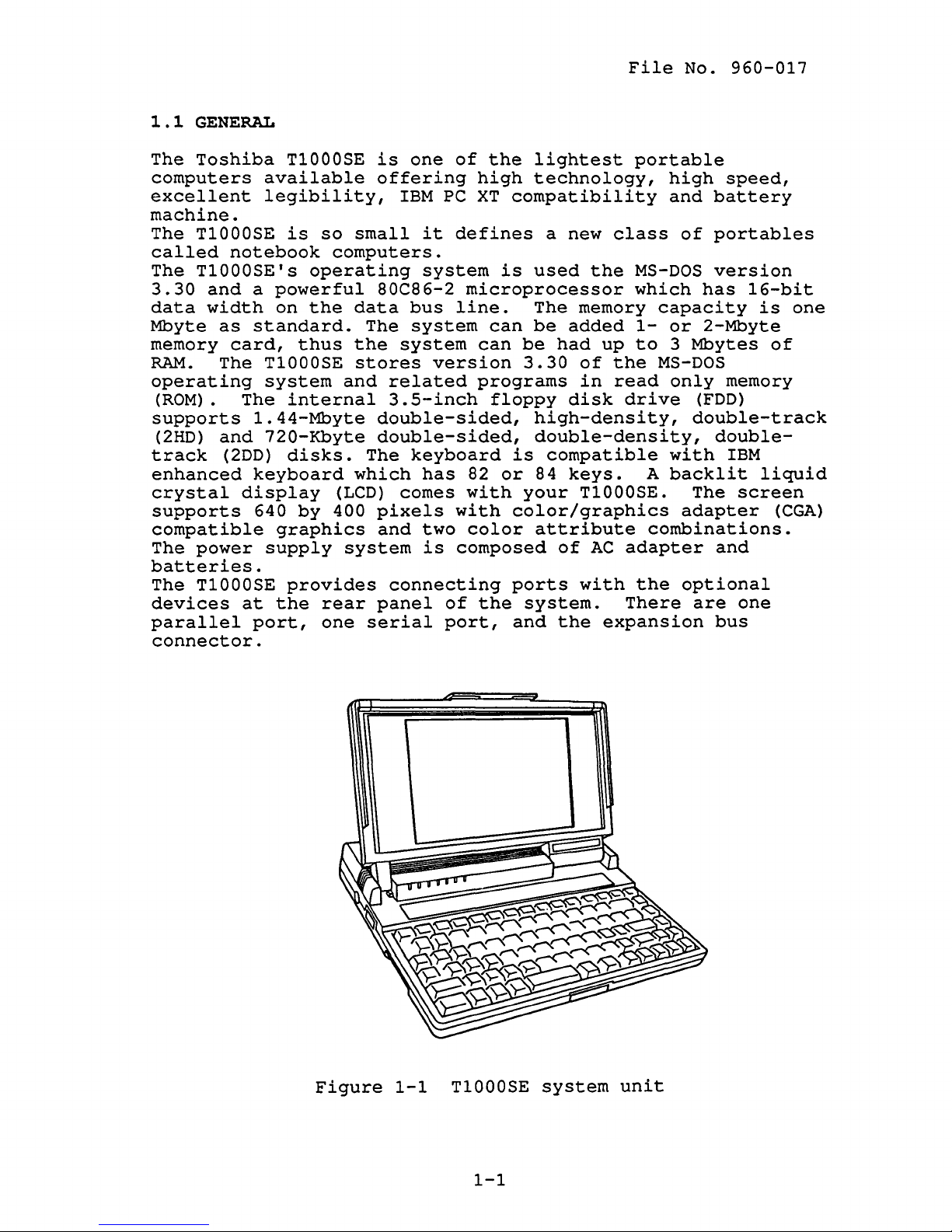
Figure
1-1
T1000SE
1-1
system
unit
File
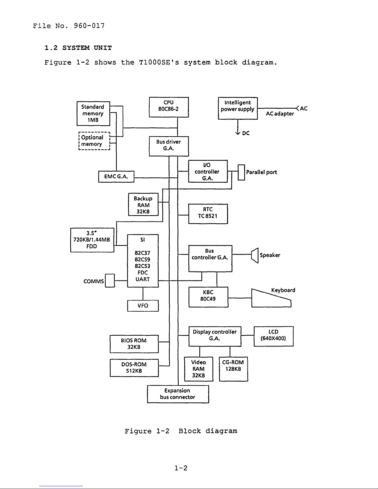
1.2
No.
SYSTEM
960-017
UNIT
Figure
1-2
shows
Standard
memory
1MB
r--------~
:
Optional
L
________
:
memory
I EMCG.A. I
3.5·
720KB/1.44MB
FDD
COMMSD-
---
-
r-
:-
.J
:-
'-
the
Backup
82C37
82CS9
82CS3
T1000SE's
CPU
80C86-2
Bus
G.A.
RAM
32KB
SI
FOC
UART
r-
1
VFO
driver
system
-
-
~
VO
controller
G.A.
RTC
TC8S21
Bus
controller
I
KBC
80C49
block
Intelligent
power
G.A.
diagram.
supply
IDC
-0
Parallel
ACadapter
-<AC
port
Speaker
~d
BIOS
DOS-ROM
S12KB
Figure
ROM
32KB
~
Expansion
bus connector
I
1-2
Display
I--
I I
Video
RAM 128KB
32KB
Block
1-2
controller
G.A.
CG-ROM
~
diagram
I---
LCD
(640X400)
The
board
T1000SE
is
composed
has
a
system
of
the
board
following
in
the
system.
components
File
No.
The
960-017
system
System
board
*
Central
*
Super
*
Variable
*
Real
processing
The
CPU
is
9.54MHz
Integration
The
Direct
Programmable
Programable
Floppy
Universal
The
time
The
date,
battery.
or
SI
is
Memory
disk
frequency
VFO
chip
clock
RTC
has
time
unit:
a
16-bit
4.77MHz
:
SI
stored
asynchronus
memory
and
the
Access
interrupt
interval
controller
oscillator
is
used
:
RTC
system
CPU
microprocessor
clock
(T9776)
following
controller
controller:
timer
:
receiver
for
(TC8521AM)
in
this
configuration
(80C86-2)
speed.
:
(TC8565)
:
FDD
chip
components
:
PIT
VFO
control
(82C53)
transmitter
(TC8568)
which
operated
DMAC
by
(82C37)
PIC
(82C59)
logic.
keeps
RTC
at
:
:
UART
(TC8570)
the
*
Keyboard
*
Memories
Standard
Backup
BIOS
Video
CG-ROM : 128
DOS-ROM : 512
*
Gate
Bus
Bus
I/O
Plasma/LCD
pin)
Expanded
pin)
controller
RAM : 32
ROM : 32
RAM : 32
arrays
controller
driver
controller
memory
RAM
gate
controller
: 1
Kbytes
Kbytes
Kbytes
Kbytes
:
gate
array
gate
controller
:
KBC
Mbyte
Kbytes
array
: BUSD-GA
array
2
(80C49)
: BUSC-GA
:
I/O
gate
array
gate
(100
(100
CONT-GA
array
pin)
: PLC2-GA
:
pin)
(100
EMC-GA
pin)
(100
(100
1-3
File
No.
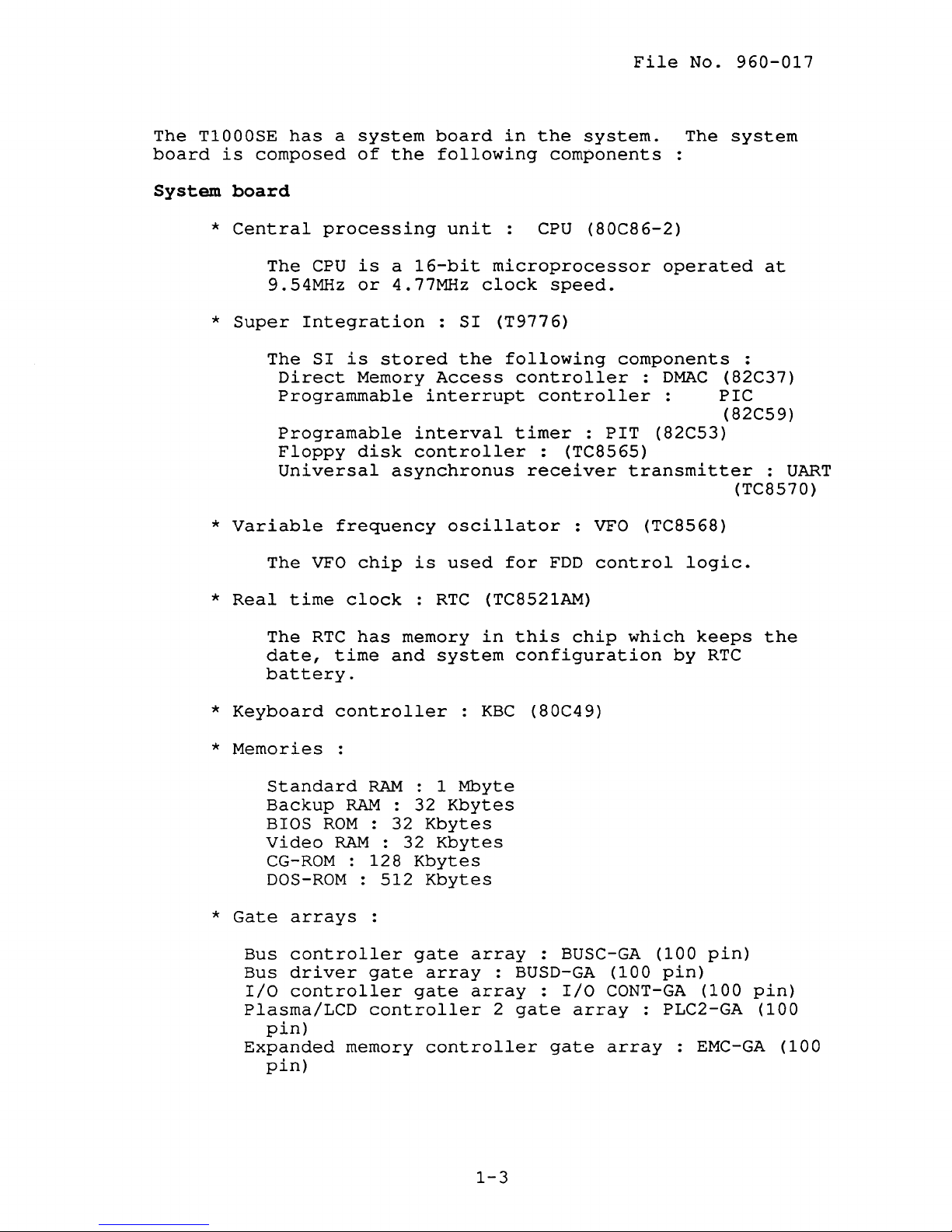
1.3
The
3.S-INCH
3.5-inch
performance,
kbyte
floppy
specifications
960-017
FLOPPY
internal
reliable,
(formatted)
disk.
The
FDD
are
DISK DRIVE
floppy
and
200
and
is
shown
described
disk
thin
drive
drive
1.44-Mbyte
in
figure
in
table
(FDD)
that
supports
(formatted)
1-3
and
1-1.
is
its
a
high
720-
3.5-inch
Figure
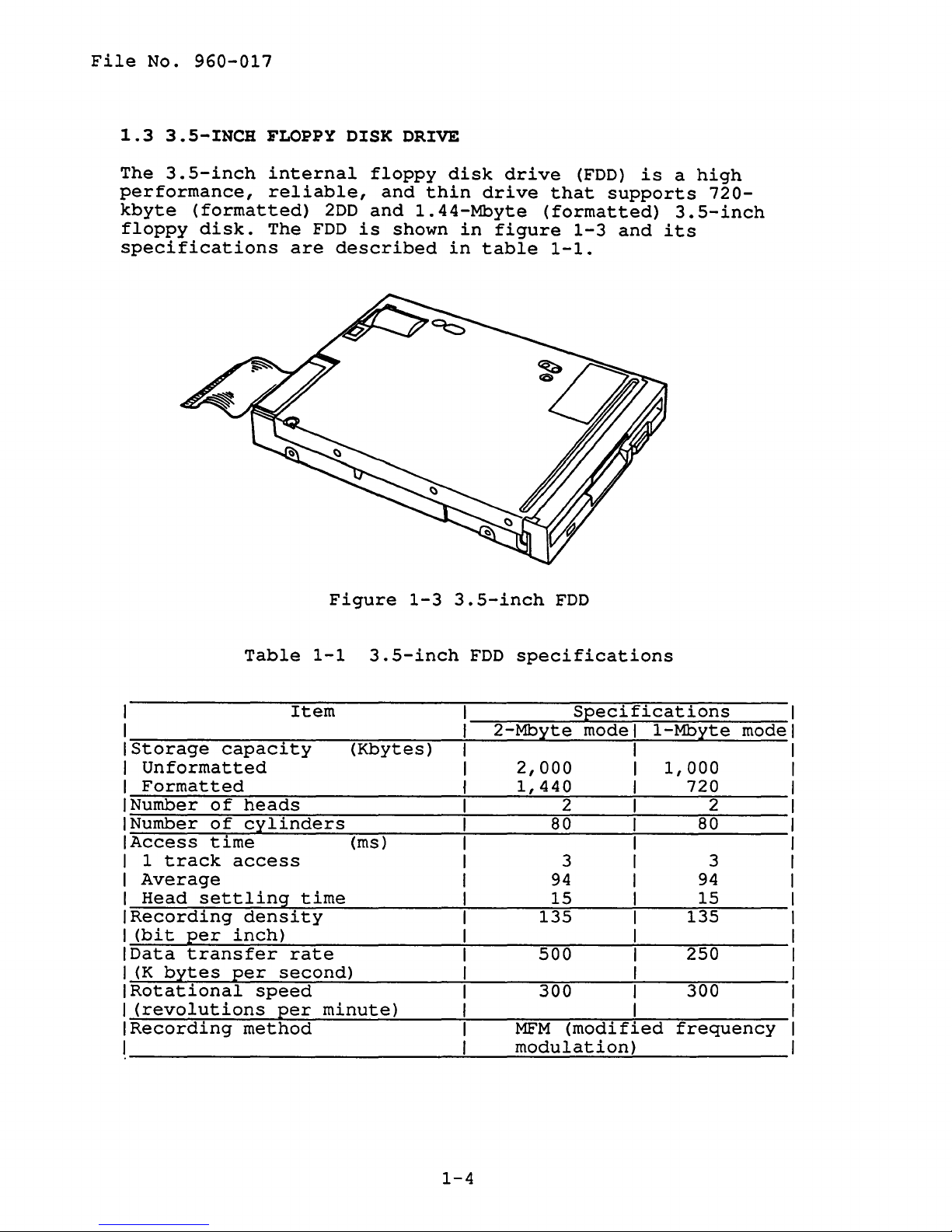
Table
I
1-1
Item
I
Storage
I
Unformatted
I
I~F~o~r~m~a~t~t~e~d~~~
I~N~u_mb~e_r'--o~f~h....;;e~a~d....;;s-:-
I~N~u~mb~e~r~o~f~c~y~1~i~n~d~e~r~s~~
IAccess
I
1
track
Average
I
I~H~e~a~d~s~e~t~t~1~i~n~g~t~i~m~e'--
IRecording
1=(~b~i~t~p~e....;;r~i~n~c~h~)
IData
1=(_K~b&y~t_e~s~p....;;e_r~s....;;e....;;c~o_n....;;d~)
IRotational
I=(~r~e~v~o~l~u~t_i~o~n~s~p....;;e~r:--m~i~n~u~t_e~)
IRecording
1
____________________________
capacity
time
access
density
transfer
method
(Kbytes)
____________
____________ ~ ______
(ms) I I
__ ~ __________
rate
________
speed
1-3
3.5-inch
3.5-inch
FDD
-""'2--.."...,Mb::--y"""'"t-e---"-m....;;o....;;d:-e-;I---=1---='Mb~y-:-t....;;e'--m-o-d;--e
~'--
__
....;;1~,_4~4~0r-
______ ~ ______
________ ~ ____
~~
____
~~
____
____
~~
__
~~~
~'--
___
FDD
specifications
Specifications
I I
2,000
~2
______
~8~0'--
____
____
I
1,000
~1
____
~1
____
~1
_____
7_2~0~--
~2~--
8~0'--
_____
3 I 3 I
94
~~1~5r-
135
~~
____
500
~~
____
300
__
MFM
m_o~d~u~1_a_t_1_·o_n~)~
(modified
I
____
~1
__
~~1~5~
I
~1
__
~~~
I
~I
__
~~~
I
~~I-.~
frequency
____________
94
_____
135
_____
250
_____
300
______
I
I
I
___
1
___ 1
1
I
1
I
I
I
I
I
~I
I
1
1-4
1
.4
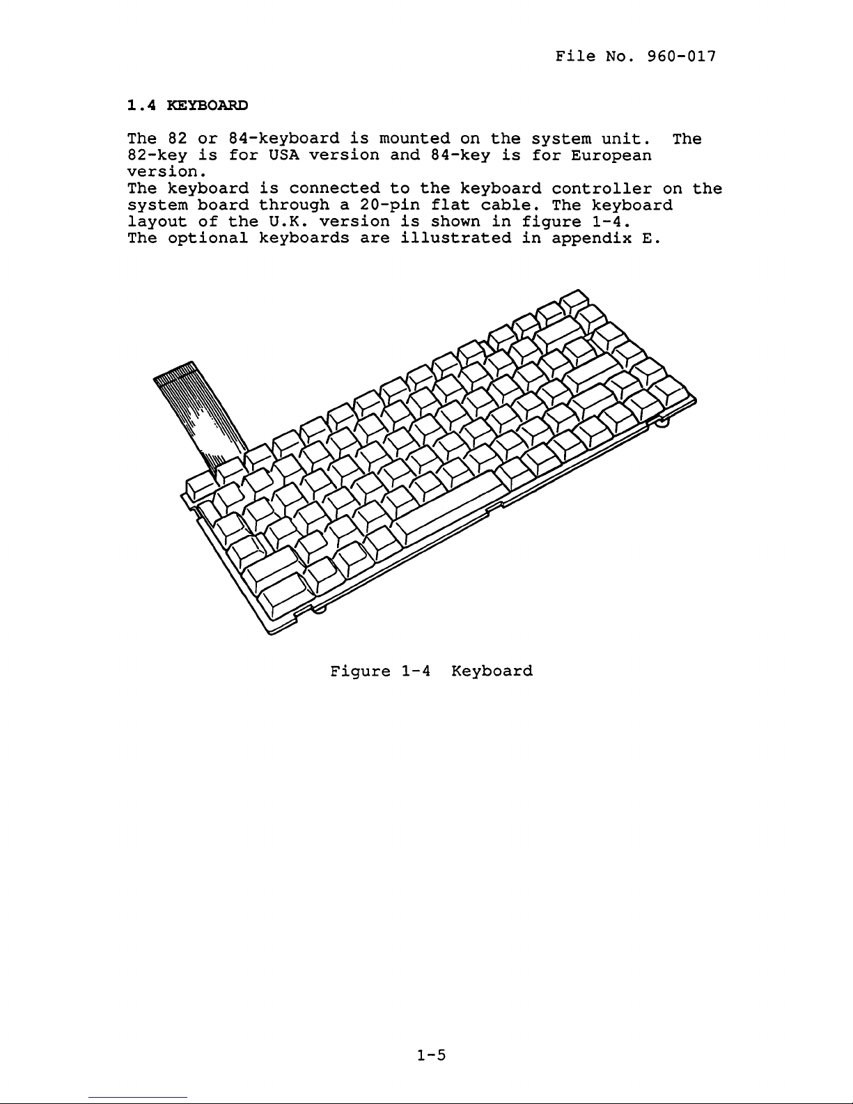
KEYBOARD
File
No.
960-017
The 82
82-key
version.
The
keyboard
system
layout
The
optional
or
84-keyboard
is
for
is
board
of
through
the
keyboards
USA
version
connected
U.K.
version
is
a
20-pin
are
mounted
and
84-key
to
the
flat
is
shown
illustrated
on
the
is
keyboard
cable.
in
figure
in
system
for
European
controller
The
appendix
unit.
keyboard
1-4.
E.
The
on
the
Figure
1-4
1-5
Keyboard
File
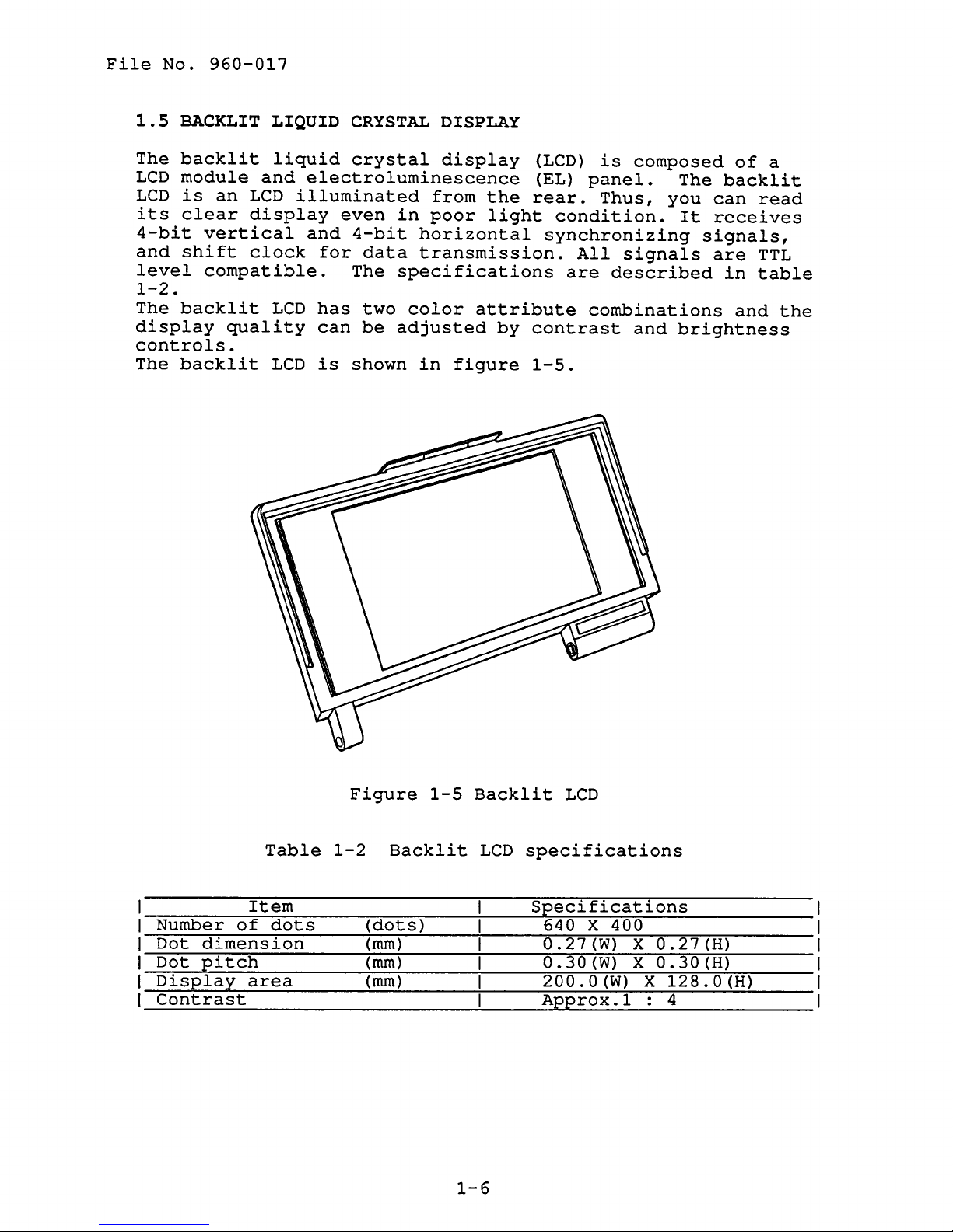
1.5
The
LCD
LCD
its
4-bit
and
level
1-2.
The
display
controls.
The
No.
960-017
BACKLIT
backlit
module
is
clear
vertical
shift
compatible.
backlit
backlit
an
LCD
display
clock
quality
LIQUID
liquid
and
CRYSTAL
crystal
electroluminescence
illuminated
even
and
4-bit
for
data
The
LCD
has
two
can
be
LCD
is
shown
DISPLAY
display
in
from
poor
the
light
horizontal
transmission.
specifications
color
adjusted
in
attribute
by
figure
(LCD)
(EL)
rear.
is
panel.
Thus,
condition.
synchronizing
All
are
signals
described
combinations
contrast
1-5.
composed
The
you
It
signals,
and
brightness
of
a
backlit
can
read
receives
are
TTL
in
table
and
the
Table
Item
Number
Dot
Dot
Display
of
dots
dimension
pitch
area
Contrast
Figure
1-2
Backlit
(dots)
(mm)
(mm)
(mm)
1-5
Backlit
LCD
1-6
LCD
specifications
Specifications
640
X
400
0.27
0.30
(W)
(W)
200.0(W)
Approx.l
X
X
0.27
0.30
X
: 4
(H)
(H)
128.0(H)
2.1
The
used
The
GENERAL
problem
to
isolate
FRUs
1.
2.
3.
4.
5.
covered
Power
System
FDD
Keyboard
Display
isolation
defective
are:
supply
board
procedures
field
unit
described
replaceable
File
in
units
No.
part
960-017
2
are
(FRUs).
Detailed
in
part
3.
The
following
problem
1.
2.
3.
4.
5.
6.
The
problem
be
used
necessary
2.2
PROBLEM
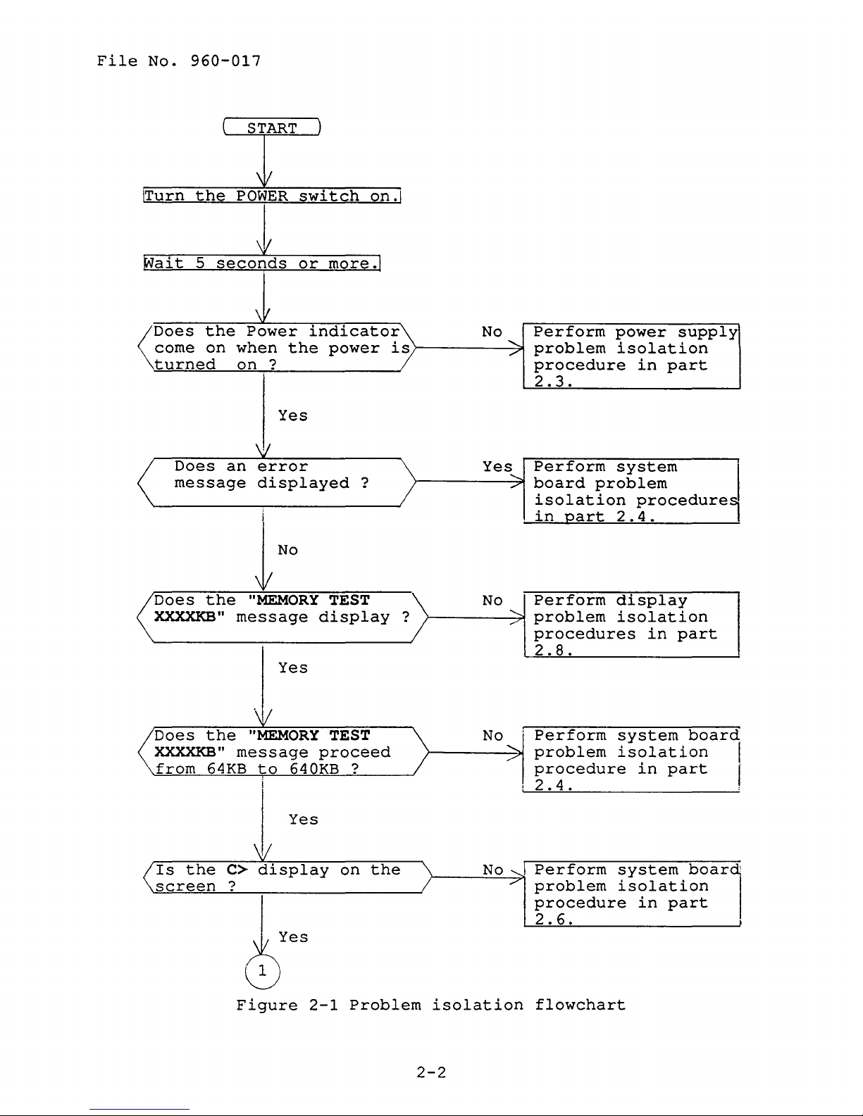
The
flowchart
determining
followings
replacement
4
and
test
items
isolation
TI000SE
Phillips
Work
disk
Cleaning
Printer
RS-232-C,
isolation
to
determine
to
isolate
ISOLATION
in
which
before
procedures
program
are
necessary
procedures.
diagnostics
head
disk
port
screwdriver
(for
kit
LED
FDD
printer
flowchart
which
a
TI000SE
FLOWCHART
figure
FRU
2-1
is
performing
operations
disk
testing)
(for
wraparound
isolation
problem.
is
used
defective.
the
instructions
are
for
implementing
FDD
testing)
connectors
described
procedures
as
a
Please
flowchart
are
described
in
section
guide
confirm
procedures.
described
the
are
for
in
2.2
the
part
can
1.
2.
No
All
disk
optional
is
in
the
equipments
FDD.
are
2-1
disconnected.
File
No.
960-017
START
Wait
<:Does
come
turned
Does
message
Does
XXXXKB"
5
seco1Lds
the
on
an
the
\'
Power
when
on?
the
Yes
\!I
error
displayed
i
"MEMORY
message
Yes
or
more
indicator
power
TEST
display
.
is
?
?
r--------~>
NO
yes
No
Perform
........
problem
./
procedure
2.3.
........
Perform
board
./
isolation
in
Perform
problem
procedures
2.8.
Qart
power
isolation
in
system
problem
procedure,
2.4.
display
isolation
in
supply
part
I
part
Does
XXXXKB"
from
Is
screen
the
the
64KB
C>
?
"MEMORY
message
to
640KB ?
Yes
display
Figure
TEST
proceed
on
2-1
the
Problem
isolation
2-2
o
N
No
problem
1L'
-"p,,-,e,-r~f
..........
procedure
2 • 4 •
I
Perform
problem
procedure
2.6.
flowchart
o_r_m
__
isolation
s_y_s_t_e
__ m __
in
part
system
isolation
in
part
b_o_a_r_d~
boar1:
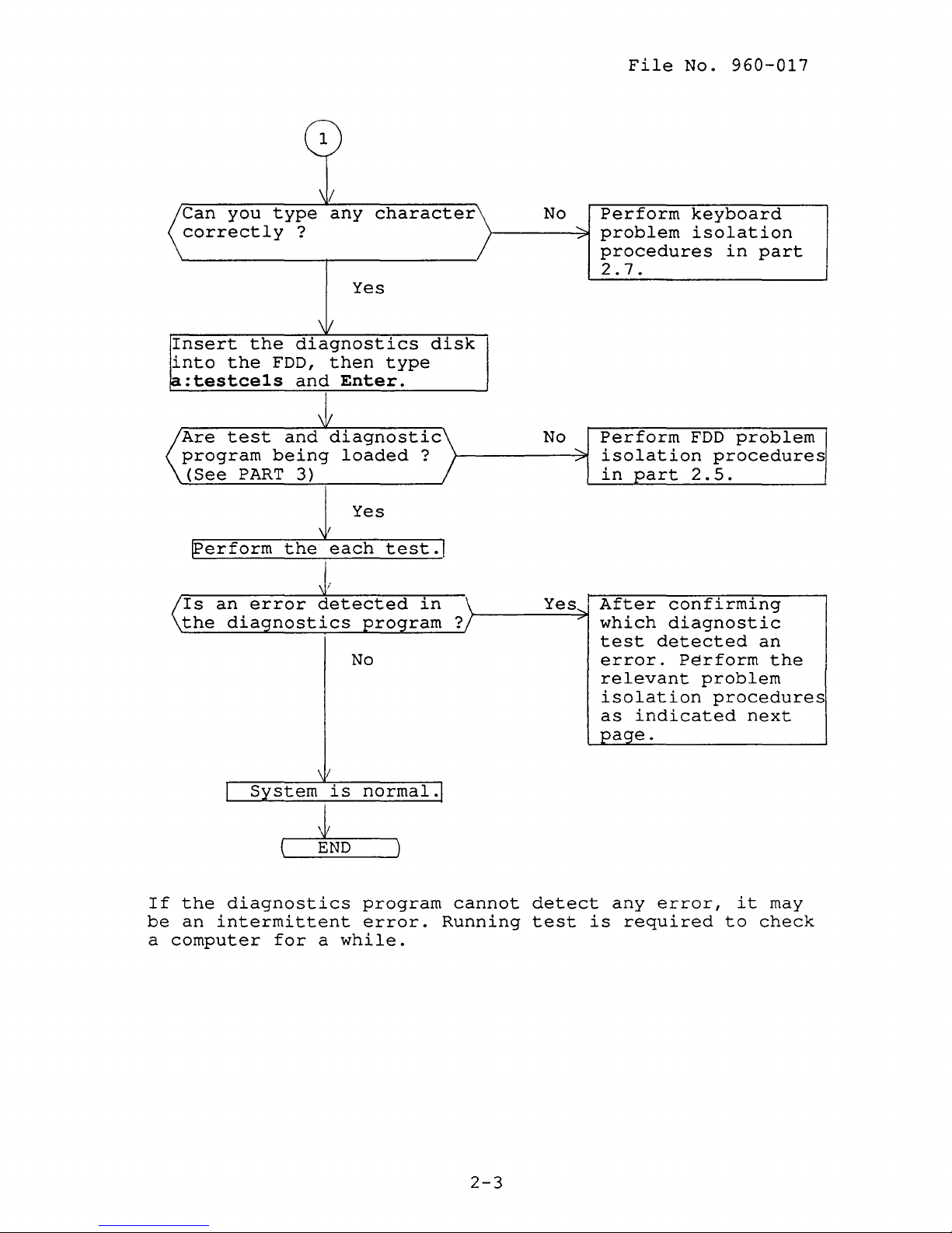
Can
you
type
correctly
Insert
into
~:testcels
the
the
FDD,
1
\/
any
character
?
Yes
\/
diagnostics
then
and
Enter.
type
disk
No
File
Perform
"'-
problem
....
procedures
2.7.
No.
960-017
keyboard
isolation
in
part
Are
test
program
(See
PART
lPerform
an
Is
the
diagnostics
I
and
being
3)
the
error
System
~
diagnostic
loaded
Yes
\ I
each
i
detected
program
No
\/
is
normal.J
END
test
?
in
.1
No
\
?
Yes,
Perform
,
isolation
..-
in
After
--
which
test
error.
relevant
isolation
as
FDD
part
2.5.
confirming
diagnostic
detected
Perform
indicated
problem
procedures
an
the
problem
procedures
next
page.
If
the
diagnostics
be
an
intermittent
a
computer
for
a
program
error.
while.
cannot
Running
2-3
detect
test
any
is
error,
required
to
it
may
check
File
No.
960-017
1.
2.
3.
If
an
error
test,
timer
display
test,
procedures
If
an
error
the
keyboard
2.6.
If
an
error
perform
2.5.
the
is
detected
test,
perform
in
section
is
detected
problem
is
detected
FDD
ASYNC
the
isolation
problem
on
system
2.4.
on
on
isolation
the
test,
the
the
system
test,
printer
board
isolation
keyboard
procedures
floppy
disk
procedures
test,
test,
in
memory
or
perform
section
test,
in
real
section
2-4
2.3
POWER
SUPPLY
PROBLEM
ISOLATION
File
PROCEDURES
No.
960-017
This
supply
section
is
continue
described
PROCEDURE 1 DC
PROCEDURE 2 Connector
PROCEDURE
DC
IN
indicator
This
adapter
wall
the
If
indicator
outlet.
indicator
the
DC
when
connecting
following
Check
1
describes
defective
with
in
1
other
this
you
If
labeled
IN
indicator
the
items.
Unplug
computer.
then
If
still
2.
section
check
lights
connect
the
AC
adapter
the
the
how
or
not.
procedures
IN
indicator
red
the
AC
adapter's
"DC
flashes
AC
adapter
Plug
wall
its
outlet
phenomenon
to
Start
are:
check
if
IN"
to
the
determine
with
as
instructed.
check
power
AC
adapter
output
flashes
red
the
computer,
from
AC
adapter
and
remains,
whether
PROCEDURE 1 and
is
supplied
to
T1000SE
voltage
red.
or
does
not
check
the
wall
into
power
on
the
perform
the
The
procedures
from
is
glow
the
outlet
the
computer,
computer.
power
AC
and
a
abnormal,
when
and
the
the
check
Check
PROCEDURE
2
Connector
The
battery
cable
board.
cable.
Check
may
Disassemble
Disassemble
1
The
AC
adapter.
the
PROCEDURE
2
check
cable
be
disconnected
Check
system
o
Battery
o
Sub
If
these
Try
again
remains,
the
system
adapter
If
is
the
procedures
that
board
connector
battery
cables
the
the
may
still
2.
connected
from
T1000SE
the
following
correctly.
connector
are
normal
system
board.
be
damaged.
its
phenomenon
to
the
the
PJ502
system
is
described
cable
-------------->
---------->
disconnected,
operation.
board
system
may
Replace
of
unit
is
If
be
a
remains,
board.
the
system
for
checking
in
part
connected
PJ502
PJ503
connect
the
phenomenon
damaged.
new
AC
perform
The
4.
to
them.
Replace
the
the
2-5
File
2.4
No.
SYSTEM
960-017
BOARD
PROBLEM
ISOLATION
PROCEDURES
This
board
continue
procedures
section
is
PROCEDURE
PROCEDURE
PROCEDURE
PROCEDURE
Message
After
(IRT)
board.
no
displayed
Check
check
power
which
If
1
describes
defective
with
other
described
1
on,
program
the
error
on
If
the
screen,
current
stored
following
the
current
pressing
appears,
or
1:
Message
2:
Printer
Test
3:
the
the
following
press
system
to
any
perform
how
to
not.
procedures
in
this
check
port
program
system
is
message
screen,
RTC
message
configuration
performs
stored
error
any
configuration
memory.
key.
check
determine
Start
as
section
LED
check
in
BIOS
appears,
perform
message
key.
will
If
This
If
appear.
another
2.
whether
with
instructed.
PROCEDURE
are:
check
initial
ROM
perform
the
program
and
it
is
in
the
error
PROCEDURE
reliability
on
the
the
appears
confirms
the
different,
You
can
RTC
memory
message
the
system
1
and
The
test
system
check
2
on
configuration
easily
1.
the
the
the
by
If
set
Check
Check
A
checksum
2
3
***SYSTEM
error
Press
If
the
At
this
another
following
time
error
WARNING:
PRESS
The
error
appears
message
ANY
IRT
occurs
program
on
or
KEYBOARD
SYSTEM
xxxx
FDD
CONFIGURATION
MEMORY
ERROR
CONFIGURATION
occured
any
key
the
message
RESUME
KEY
TO
on
the
none
ERROR
ERROR
in
for
message
resumed
FAILURE.
CONTINUE.
tests
the
screen.
appears,
IRT
ERROR
the
default
appears,
data
appears,
the
system
program,
If
the
perform
ERROR***
configuration
set
....
press
will
perform
following
be
board.
the
PROCEDURE
any
erased.
check
If
error
error
RAM.
key.
If
3.
an
message
3.
2-6
File
No.
960-017
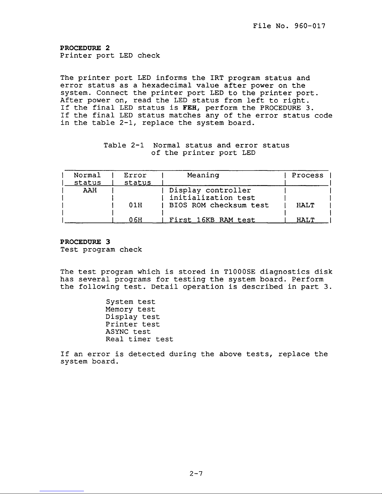
PROCEDURE
Printer
The
error
system.
After
If
the
If
the
in
the
port
printer
status
Connect
power
final
final
table
Normal
status
AAH
2
port
on,
Table
LED
as
LED
LED
2-1,
Error
status
01H
06H
check
LED
informs
a
hexadecimal
the
printer
read
the
status
status
replace
2-1
Normal
of
the
value
port
LED
status
is
FEB,
matches
the
system
status
the
printer
Meaning
Display
initialization
BIOS
First
ROM
16KB
IRT
program
after
LED
to
from
perform
any
of
board.
and
port
controller
checksum
RAM
the
left
the
the
error
LED
test
test
status
power
on
printer
to
PROCEDURE
error
status
test
and
the
port.
right.
status
Process
HALT
HALT
3.
code
PROCEDURE
Test
The
has
the
If
system
program
test
several
following
an
error
board.
3
check
program
programs
test.
System
Memory
Display
Printer
ASYNC
Real
is
which
Detail
test
test
test
test
test
timer
detected
for
test
is
stored
testing
during
in
the
operation
the
T1000SE
system
is
above
diagnostics
board.
described
tests,
Perform
in
replace
part
disk
3.
the
2-7
File
2.5
No.
FLOPPY
960-017
DISK DRIVE
PROBLEM
ISOLATION
PROCEDURES
This
disk
section
drive
continue
procedures
PROCEDURE
PROCEDURE
PROCEDURE
PROCEDURE
Format
Prepare
FORMAT
If
the
check
the
command.
floppy
items.
Check
Check
1
2
describes
is
defective
with
described
1
new
Check
not
perform
Check
correctly.
When
When
If
FORMAT
check
try
If
still
3.
other
1:
2:
3:
floppy
disk
that
light,
that
media
media
3.
again.
how
or
procedures
in
this
Format
Test
program
Connector
disk,
is
not
the
perform
check
2.
the
type
type
command
If
FORMAT
the
phenomenon
to
determine
not.
section
check
check
the
formatted,
FDD
indicator
the
MS-DOS
is
2DD,
is
2HD,
is
command
Start
as
instructed.
are:
check
format
check
PROCEDURE
FORMAT
use
use
used
correctly,
is
remains,
whether
with
it
using
the
lights.
3.
command
the
FORMAT/3
the
FORMAT
not
perform
the
floppy
PROCEDURE 1 and
The
MS-DOS
following
If
it
does
If
it
lights,
is
used
command.
command.
used
perform
correctly,
the
the
check
Check
3
Perform
the
3.S-inch
PROCEDURE
FDD.
2.
head
If
cleaning
still
2-8
by
remains,
cleaning
perform
kit
the
of
the
File
No.
960-017
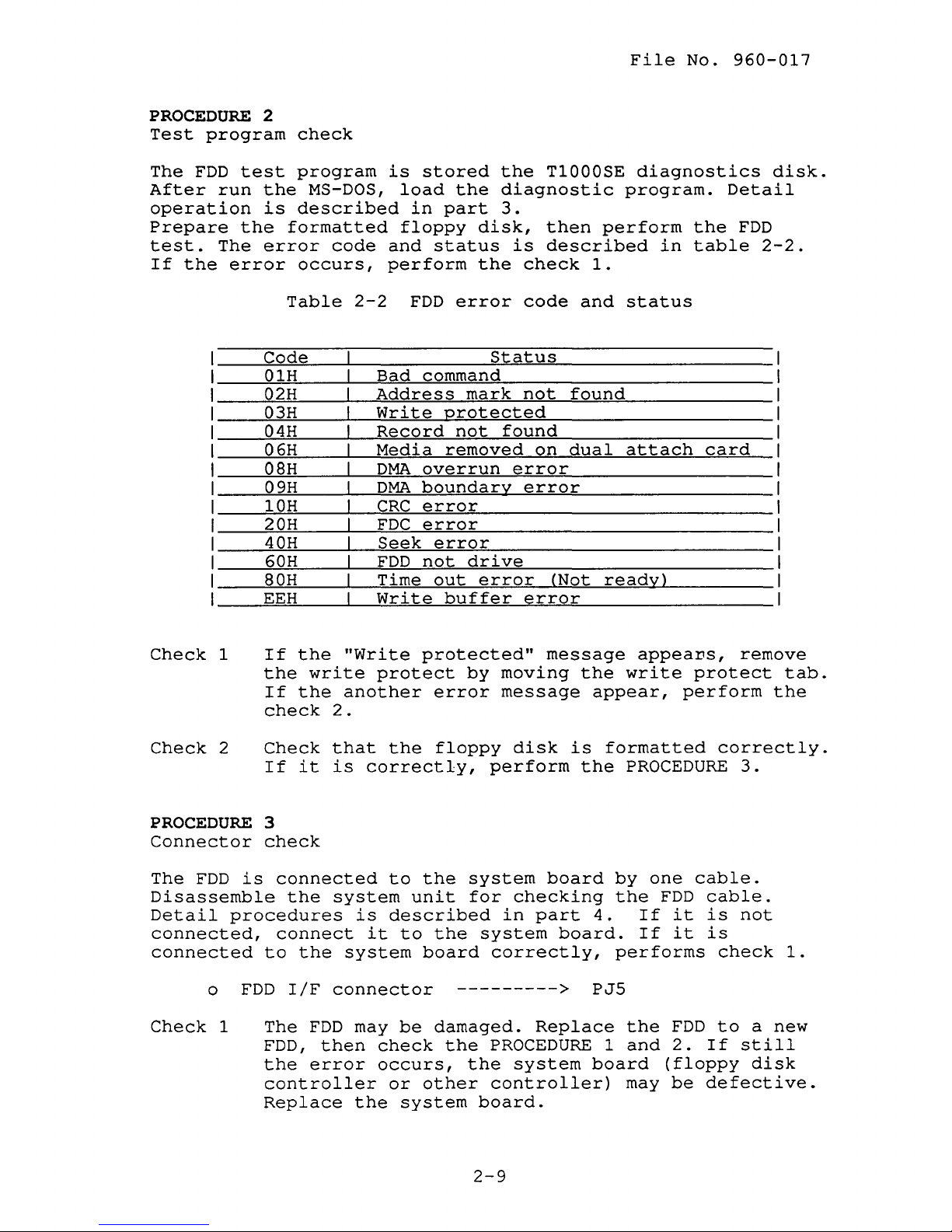
PROCEDURE
Test
The
After
operation
Prepare
test.
If
program
FDD
run
The
the
test
the
error
2
check
program
the
MS-DOS,
is
described
formatted
error
occurs,
Table
Code
01H
02H
03H
04H
06H
08H
09H
10H
20H
40H
60H
80H
EEH
code
2-2
is
stored
load
in
floppy
and
status
perform
FDD
Bad
command
Address
Write
Record
Media
DMA
overrun
DMA
boundary
CRC
error
FDC
error
Seek
FDD
Time
Write
error
not
out
the
the
diagnostic
part
protected
removed
buffer
disk,
the
error
mark
not
drive
error
3.
is
Status
found
error
T1000SE
then
described
check
code
not
found
on
dual
error
(Not
error
perform
1.
and
ready)
diagnostics
program.
the
in
table
status
attach
disk.
Detail
FDD
2-2.
card
Check
Check
PROCEDURE
Connector
The
Disassemble
Detail
connected,
connected
Check
1
2
FDD
is
procedures
o
FDD
1
If
the
the
write
If
the
check
Check
If
3
check
connected
connect
to
The
FDD,
the
controller
Replace
it
the
the
IfF
FDD
error
2.
that
is
system
connector
then
"Write
protect
another
the
correctly,
to
is
described
it
system
may
check
occurs,
or
the
protected"
error
floppy
the
unit
to
the
board
--------->
be
damaged.
the
other
system
message
by
moving
message
disk
perform
system
for
checking
in
system
correctly,
PROCEDURE 1 and
the
system
controller)
board.
the
appear,
is
the
board
part
board.
PJ5
Replace
board
4.
appeaDS,
write
formatted
PROCEDURE
by
one
the
FDD
If
it
If
it
performs
the
FDD
2.
(floppy
may
be
remove
protect
perform
correctly.
cable.
cable.
is
not
is
check
to
If
still
defective.
3.
a
disk
tab.
the
1.
new
2-9
File
No.
2.6
960-017
KEYBOARD
PROBLEM
ISOLATION
PROCEDURES
This
is
with
described
PROCEDURE
Test
The
disk.
described
If
does
PROCEDURE
Connector
The
flat
keyboard
If
correctly,
section
defective
other
PROCEDURE
PROCEDURE
program
keyboard
Perform
the
error
not
keyboard
cable.
it
is
describes
or
procedures
in
this
1:
2:
1
check
test
in
part
occurs,
occur,
2
check
is
Disassemble
cable.
not
connected,
perform
not.
section
Test
Connector
program
the
test
3.
the
keyboard
connected
Detail
the
how
Start
as
instructed.
are:
program
is
program.
perform
to
the
procedures
connect
check
to
determine
with
check
check
stored
the
is
the
system
1.
whether
PROCEDURE 1 and
The
procedures
in
T1000SE
Details
PROCEDURE
normal.
system
unit
is
it.
operation
board
for
described
If
it
2.
is
the
continue
diagnostics
is
If
the
by
one
checking
in
part
conRected
keyboard
error
22-pin
the
4.
Check
o
Keyboard
1
The
keyboard
to
a
still
system
board.
IfF
new
error
board
connector
may
one,
occurs,
may
then
be
damaged.
check
the
be
damaged.
-------->
Replace
the
PROCEDURE
keyboard
Replace
PJ8
the
1.
controller
the
keyboard
If
on
the
system
2-10
File
No.
960-017
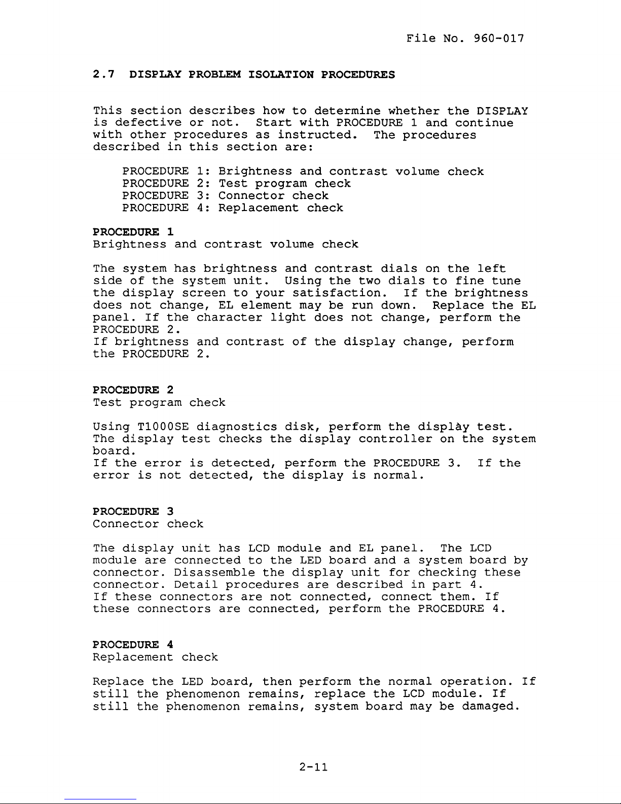
2.7
This
is
with
DISPLAY
section
defective
other
described
PROCEDURE
PROCEDURE
PROCEDURE
PROCEDURE
PROCEDURE
Brightness
The
system
side
the
does
panel.
of
the
display
not
If
PROCEDURE
If
brightness
the
PROCEDURE
PROBLEM
describes
or
procedures
in
this
1:
2:
3:
4:
1
and
has
system
screen
change,
the
character
2.
and
2.
ISOLATION
not.
section
Brightness
Test
Connector
Replacement
contrast
brightness
unit.
to
EL
element
contrast
how
to
Start
as
instructed.
are:
program
check
volume
and
Using
your
satisfaction.
light
of
PROCEDURES
determine
with
and
PROCEDURE 1 and
contrast
check
check
check
contrast
the
may
be
does
the
display
two
run
not
whether
The
volume
dials
dials
down.
change,
the
continue
procedures
check
on
the
to
fine
If
the
brightness
Replace
perform
change,
DISPLAY
left
tune
the
the
perform
EL
PROCEDURE
Test
Using
The
program
T1000SE
display
board.
If
the
error
error
is
PROCEDURE
Connector
The
display
module
are
connector.
connector.
If
these
these
connectors
PROCEDURE
Replacement
Replace
still
still
the
the
the
2
check
diagnostics
test
is
detected,
not
detected,
3
check
unit
connected
Disassemble
Detail
connectors
4
check
LED
board,
phenomenon
phenomenon
checks
the
has
LCD
to
the
procedures
are
are
connected,
then
remains,
remains,
disk,
the
perform
display
module
the
display
not
perform
display
the
and
LED
board
are
described
connected,
perform
perform
replace
system
the
controller
PROCEDURE
is
normal.
EL
panel.
and
unit
for
connect
the
the
normal
the
board
display
on
3.
The
a
system
checking
in
part
them.
PROCEDURE
operation.
LCD
module.
may
be
test.
the
system
If
the
LCD
board
these
4.
If
4.
If
damaged.
by
If
2-11
File
No.
960-017
(This
page
is
intentionally
blank.)
2-12
3.1
GENERAL
File
No.
960-017
This
the
There
program
part
explains
functions
are
14
module
of
programs
(DIAGNOSTIC TEST
The
The
service
1.
2.
3.
4.
5.
test
1.
2.
3.
4.
5.
6.
7.
8.
9.
program
DIAGNOSTIC TEST
RUNNING
LOG
UTILITIES
HEAD
CLEANING
SYSTEM
program
SYSTEM
MEMORY
KEYBOARD
DISPLAY TEST
FLOPPY DISK TEST
PRINTER TEST
ASYNC
REAL
TEST
TIMER TEST
EXPANSION TEST
test
all
and
hardware
grouped
(DIAGNOSTICS
MENU)
.
module
is
TEST
CONFIGURATION
module
is
composed
TEST
TEST
TEST
diagnostics
modules
into
MENU)
two
and
composed
of
test
of
programs.
the
modules:
program
of
5
tasks:
9
tests:
That
T1000SE.
the
module
checks
service
The
following
diagnostic
1.
2.
3.
4.
5.
Service
selecting
described
items
programs.
T1000SE
Formatted
Cleaning
Printer
(For
printer
RS-232-C
(For
ASYNC
personnel
the
appropriate
in
section
are
diagnostics
work
disk
disk
kit
wraparound
wraparound
wraparound
wraparound
can
use
3.2.
necessary
disk
(For
(For
connector
connector
test)
these
program
for
FDD
head
test)
programs
and
carrying
test)
cleaning)
to
operation
out
isolate
procedures
the
test
problems
and
by
3-1
File
No.
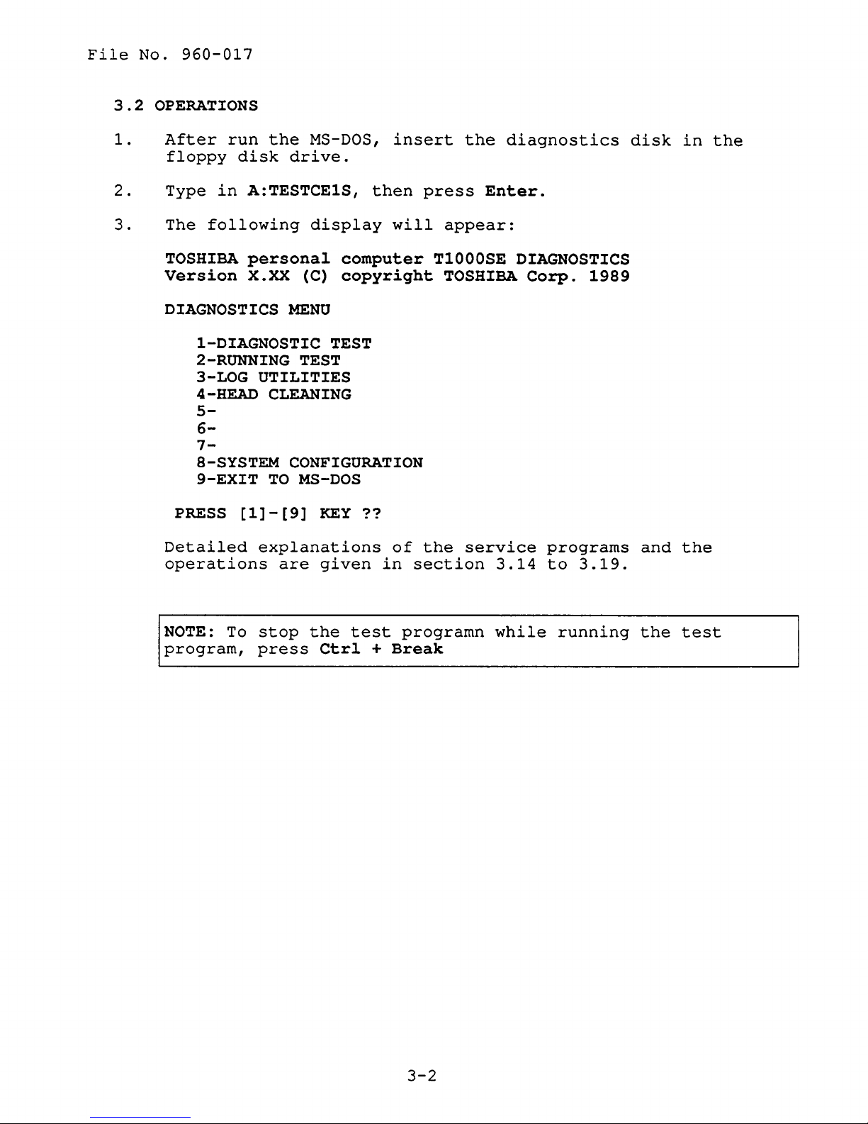
3.2
OPERATIONS
960-017
1.
2.
3.
After
floppy
Type
The
TOSHIBA
Version
run
the
disk
in
A:TESTCE1S,
following
personal
X.XX (C)
DIAGNOSTICS
1-DIAGNOSTIC
2-RUNNING
3-LOG UTILITIES
4-HEAD
CLEANING
5-
6-
7-
8-SYSTEM
9-EXIT
PRESS
Detailed
operations
TO
[1]-[9]
explanations
are
MS-DOS,
insert
drive.
then
display
will
computer
copyright
MENU
TEST
TEST
CONFIGURATION
MS-DOS
KEY??
of
given
in
section
the
press
appear:
T1000SE
TOSHIBA
the
service
diagnostics
Enter.
DIAGNOSTICS
Corp.
programs
3.14
to
1989
3.19.
disk
and
in
the
the
NOTE:
program,
To
stop
press
the
Ctrl
test
programn
+
Break
while
running
the
test
3-2
File
No.
960-017
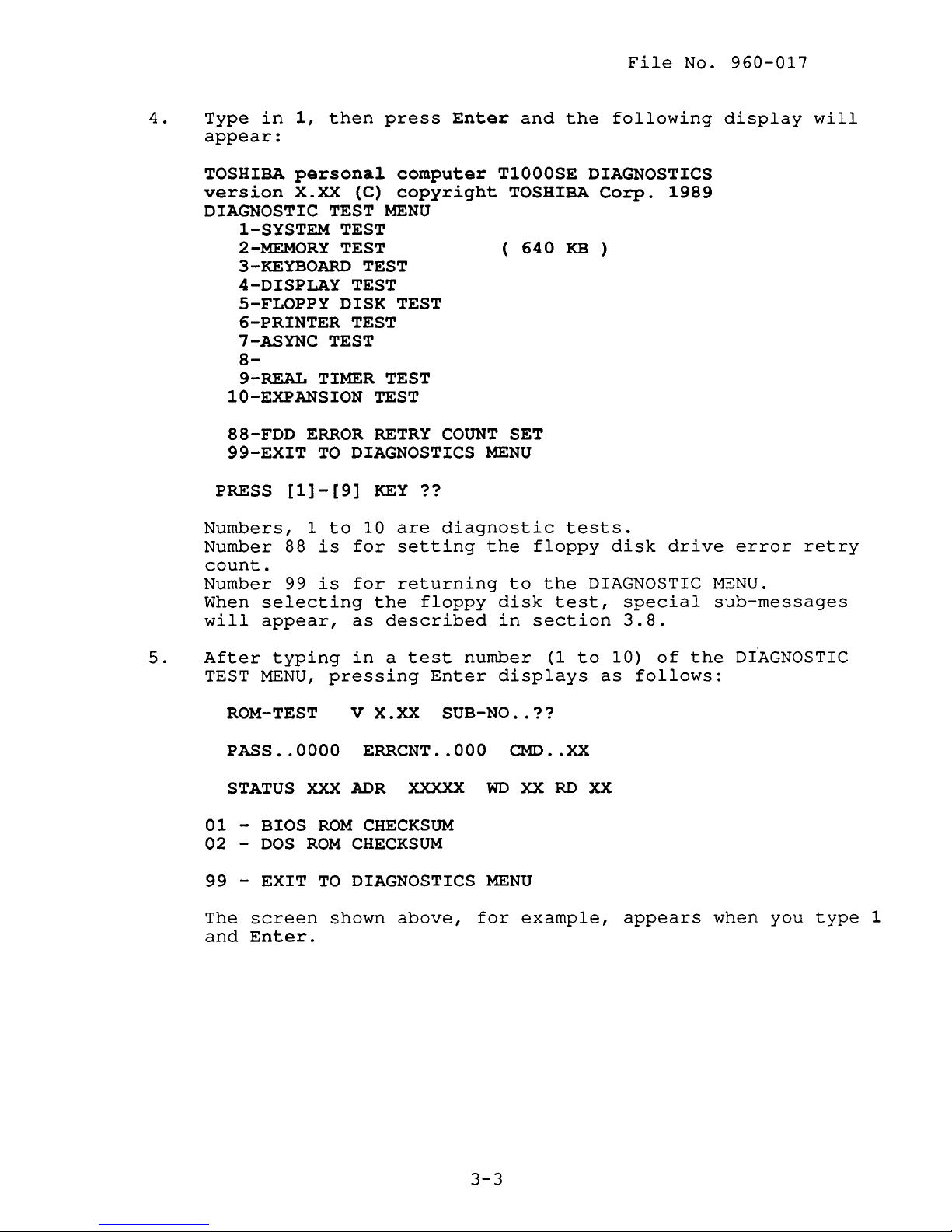
4.
Type
in
1,
then
appear:
TOSHIBA
version
personal
X.XX (C)
DIAGNOSTIC TEST
1-SYSTEM TEST
2-MEMORY
3-KEYBOARD
4-DISPLAY
5-FLOPPY
6-PRINTER
TEST (
TEST
TEST
DISK TEST
TEST
7-ASYNC TEST
8-
9-REAL TIMER TEST
10-EXPANSION TEST
88-FDD
99-EXIT
PRESS
Numbers,
Number
ERROR
TO
[1]-[9]
1
to
88
is
DIAGNOSTICS
for
count.
Number
When
will
99
is
selecting
appear,
for
as
press
computer
copyright
MENU
RETRY
KEY??
10
are
setting
returning
the
described
Enter
COUNT
diagnostic
floppy
and
T1000SE
TOSHIBA
640
SET
MENU
the
floppy
to
disk
in
section
the
following
DIAGNOSTICS
Corp.
KB
)
tests.
disk
the
DIAGNOSTIC
test,
1989
drive
special
3.8.
display
error
will
retry
MENU.
sub-messages
5.
After
TEST
typing
MENU,
ROM-TEST
PASS
..
STATUS
01 -BIOS
02 -DOS
99 -EXIT
The
screen
and
Enter.
pressing
0000
XXX
ROM
ROM
TO
shown
in
a
test
number
Enter
displays
v X.XX SUB-NO
ERRCNT
ADR
CHECKSUM
CHECKSUM
DIAGNOSTICS
..
XXXXX
above,
000
WD
MENU
for
(1
..
??
CMD
..
XX
RD
example,
to
XX
as
XX
10)
follows:
appears
of
the
DIAGNOSTIC
when
you
type
1
3-3
File
No.
960-017
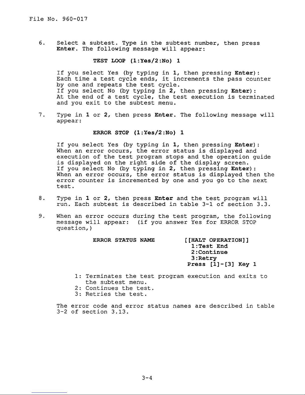
6.
7.
Select
Enter.
If
you
Each
by
If
At
and
Type
appear:
If
When
execution
is
If
When
error
test.
time
one
you
the
you
in
you
an
displayed
you
an
counter
a
subtest.
The
TEST
select
a
and
select
end
exit
1
or
ERROR
select
error
of
select
error
following
LOOP
Yes
test
repeats
of
to
2,
No
a
cycle
test
the
then
STOP
Yes
occurs,
the
test
on
the
No
(by
occurs,
is
incremented
Type
in
message
(1:Yes/2:No)
(by
typing
ends,
the
test
(by
typing
cycle,
subtest
press
(1:Yes/2:No)
(by
typing
the
program
right
typing
the
the
will
in
it
cycle.
in
the
menu.
Enter.
in
error
side
in
error
by
subtest
appear:
1
1,
then
increments
2,
then
test
The
1
1,
then
status
stops
of
the
2,
then
status
one
number,
pressing
pressing
execution
following
pressing
is
and
the
display
pressing
is
and
you
then
the
pass
Enter)
is
message
displayed
operation
screen.
Enter)
displayed
go
to
press
Enter)
counter
:
terminated
Enter)
and
guide
:
then
the
next
:
will
:
the
8.
9.
Type
run.
When
message
question,)
The
3-2
in
Each
an
1:
2:
3:
error
of
1
or
2,
subtest
error
will
appear:
ERROR
Terminates
the
subtest
Continues
Retries
code
section
then
occurs
STATUS
the
the
and
3.13.
press
is
described
during
the
menu.
test.
error
(if
NAME
test
test.
Enter
the
you
program
status
and
in
table
test
answer
names
the
test
3-1
program,
Yes
for
program
of
section
the
ERROR
following
STOP
[[HALT OPERATION]]
l:Test
End
2:Continue
3:Retry
Press
execution
are
[1]-[3]
and
described
Key
exits
in
will
3.3.
1
to
table
3-4
File
No.
960-017
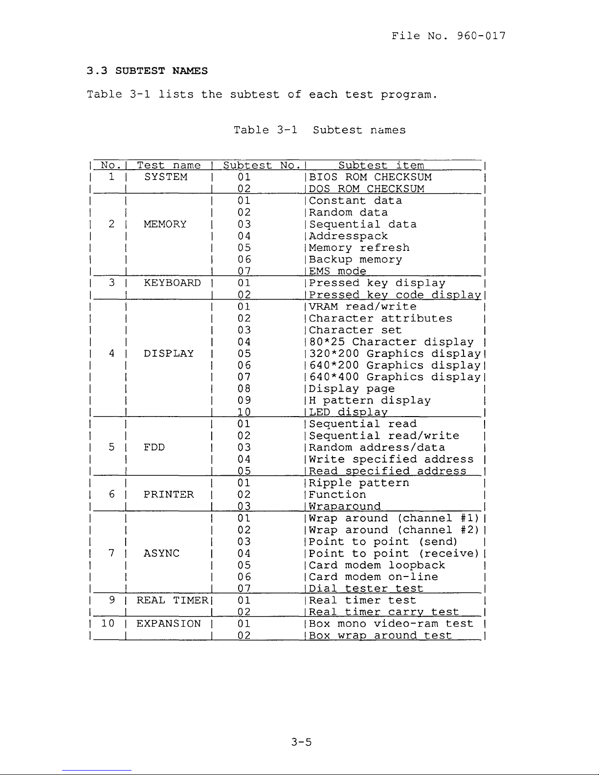
3.3
Table
No.
1 I
2 I
3 I
4
5
6
7
10
SUBTEST
3-1
I
Test
SYSTEM
I
I
I
MEMORY
I
I
I
I
KEYBOARD
I
DISPLAY
FDD
PRINTER
ASYNC
9
REAL
EXPANSION
NAMES
lists
name
TIMER
the
subtest
Table
Subtest
01
02
01
02
03
04
05
06
07
01
02
01
02
03
04
05
06
07
08
09
10
01
02
03
04
05
01
02
03
01
02
03
04
05
06
07
01
02
01
02
of
3-1
No.
each
test
Subtest
Subtest
BIOS
DOS
ROM
ROM
Constant
Random
Sequential
Addresspack
Memory
Backup
EMS
mode
Pressed
Pressed
VRAM
read/write
Character
Character
80*25
Character
1320*200
640*200
640*400
Display
H
pattern
LED
display
Sequential
Sequential
Random
Write
Read
specified
specified
Ripple
Function
Wraparound
Wrap
Wrap
Point
IPoint
ICard
ICard
IDial
IReal
IReal
IBox
IBox
around
around
to
to
modem
modem
tester
timer
timer
mono
wrap
program.
nctmes
item
CHECKSUM
CHECKSUM
data
data
data
refresh
memory
key
display
key
code
attributes
set
Graphics
Graphics
Graphics
page
display
read
read/write
address/data
address
pattern
(channel
(channel
point
point
loopback
on-line
test
test
carry
video-ram
around
display
display
display
display
display
address
#1)
#2)
(send)
(receive)
test
test
test
3-5
File
No.
960-017
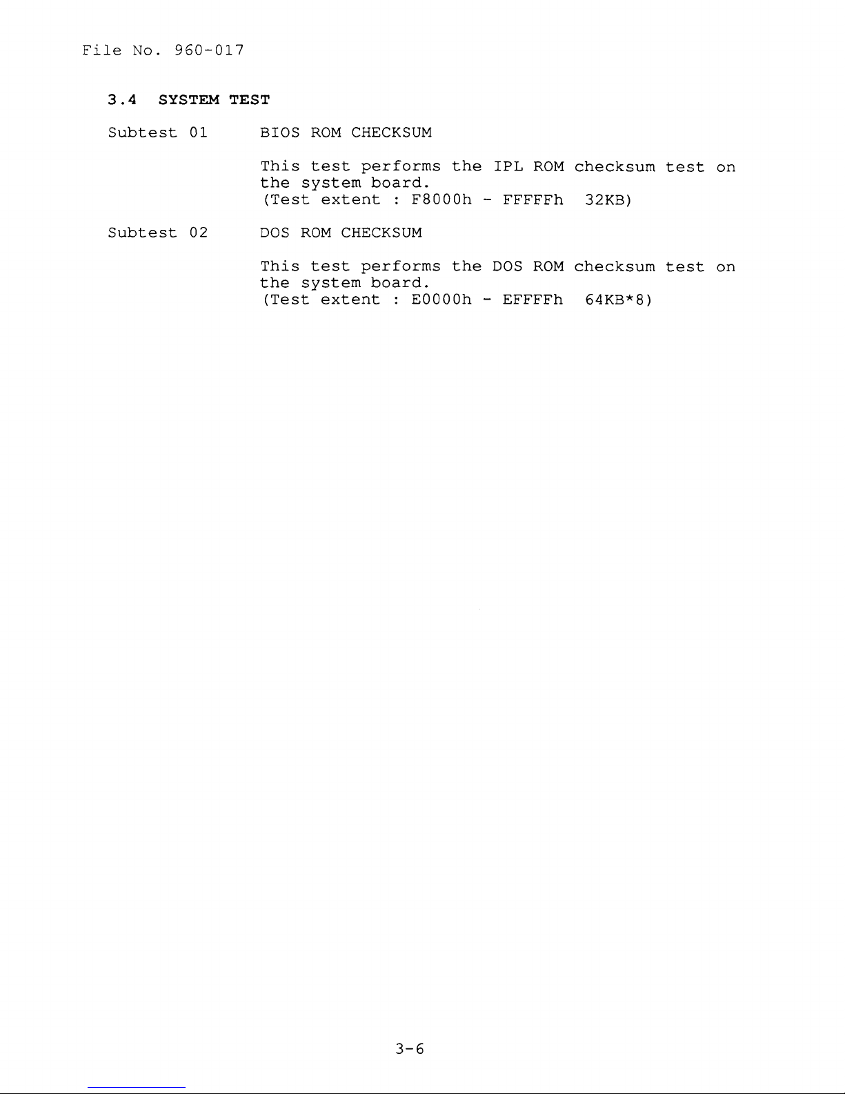
3.4
Subtest
Subtest
SYSTEM TEST
01
BIOS
This
the
02
DOS
This
the
(Test
(Test
ROM
test
system
extent
ROM
CHECKSUM
test
system
extent
CHECKSUM
performs
board.
:
F8000h
performs
board.
:
EOOOOh -EFFFFh
the
the
IPL
-
FFFFFh
DOS
ROM
ROM
checksum
32KB)
checksum
64KB*8)
test
test
on
on
3-6
File
No.
960-017
3.5
Subtest
Subtest
Subtest
Subtest
MEMORY
01
02
03
04
TEST
Constant
This
memory
the
The
'FFh'
Random
This
memory
the
Sequential
This
conventional
compares
The
Addresspack
data
subtest
(640KB),
original
constant
.
data
subtest
(640KB),
original
subtest
it
sequential
writes
data.
data
writes
data.
data
writes
memory
with
then
then
the
data
constant
reads
is
'OOh',
random
reads
sequential
(640KB),
original
is
'OOh'
data
and
'55h',
data
and
then
to
to
compares
to
conventional
compares
data
reads
data
repeatedly.
'FFh'.
conventional
it
'AAh',
it
to
and
with
and
with
Subtest
Subtest
Subtest
05
06
07
This
conventional
compare
Memory
This
memory
with
'55h',
between
Backup
This
'OOh')
subtest
it
refresh
subtest
(640KB),
the
original
'AAh',
the
memory
subtest
and
packs
memory
with
writes
write
writes
address
(Exclusive-ORring)
to
memory
and
compares
and
after
EMS
mode
This
address
('03h')
subtest
(addressed
it
the
tests
'DOOOOh')
every
the
then
and
with
test
64KB
test
(640KB),
original
data
reads
data.
'FFh'.
and
the
data
pattern
high/low
FOOOOh
the
data
EMS
and
block
in
the
address
to
conventional
and
The
There
read
('FFh',
data
of
to
original
is
preserved.
memory
select
same
and
then
reads
data.
compares
data
is
is
operations.
'AAh',
created
the
F07FFh),
data.
(page
way
writes
'OOh',
a
delay
offset
frame
register
as
(6).
data
and
it
'55h',
by
XORing
address
then
Before
to
and
reads
3-7
File
No.
960-017
3.6
Subtest
KEYBOARD
01
TEST
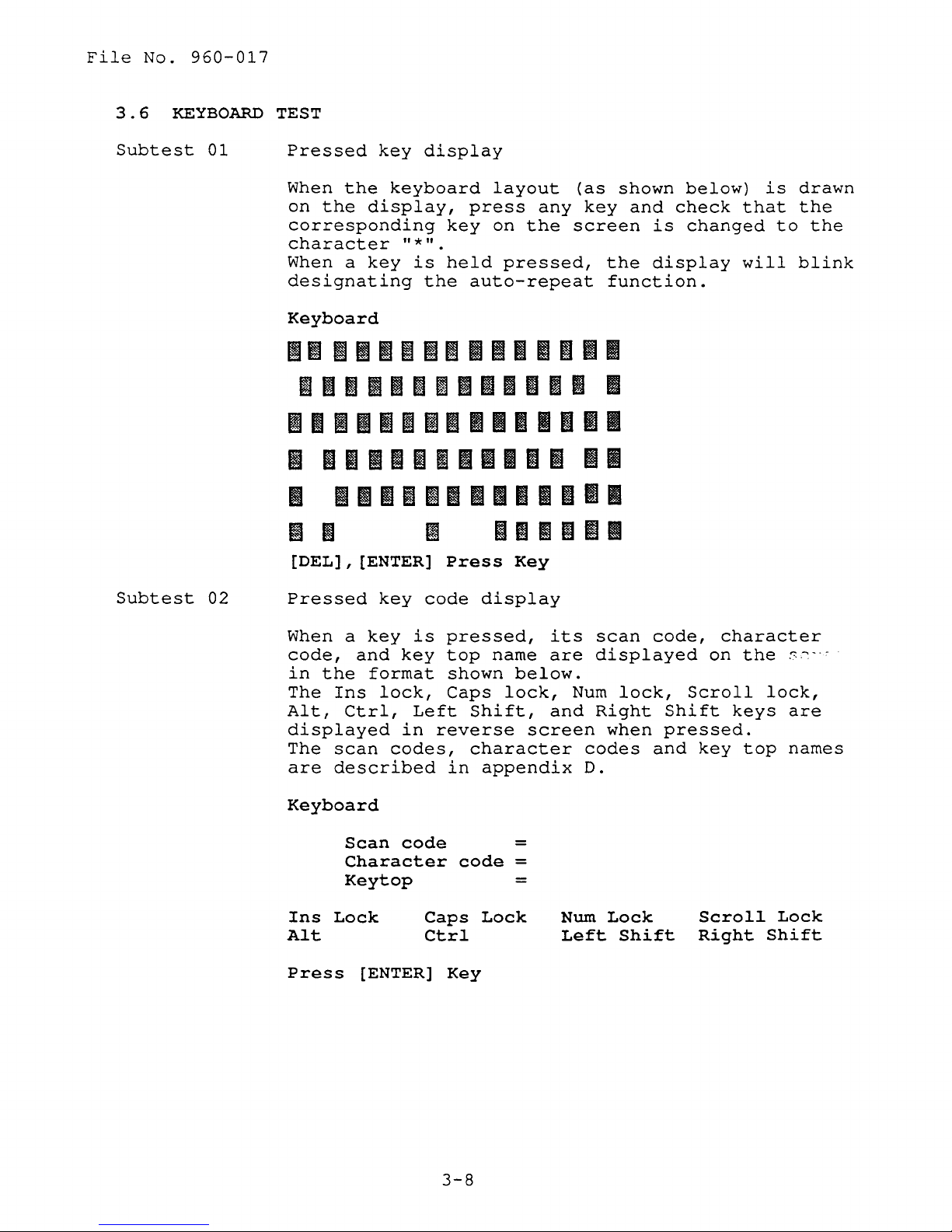
Pressed
When
on
the
corresponding
character
When a
designating
Keyboard
the
display,
key
key
display
keyboard
"*".
is
the
layout
press
key
on
held
pressed,
auto-repeat
any
the
(as
key
screen
the
function.
Imlll~lmll6I~mll
~lmlmm~lllmlm&l
11
Imlllmllllmlllli
Ii
mmlllmllllft11
I
Ilmmlillmlmlli
[DEL],
[ENTER]
Press
Key
II
shown
and
is
display
below)
check
changed
is
that
will
to
drawn
the
the
blink
Subtest
02
Pressed
When a
code,
in
The
Alt,
displayed
The
are
Keyboard
and
the
Ins
Ctrl,
scan
described
Scan
Character
Key
Ins
Lock
Alt
Press
[ENTER]
key
key
key
format
lock,
Left
in
codes,
code
top
code
is
pressed,
reverse
Caps
Ctrl
display
top
name
shown
Caps
Shift,
character
in
appendix
code
Lock
Key
below.
lock,
screen
=
=
=
its
are
Num
and
Num
Left
scan
displayed
lock,
Right
when
codes
D.
Lock
Shift
code,
Scroll
Shift
pressed.
and
key
Scroll
Right
character
on
the
lock,
keys
top
Shift
s-_·'
are
names
Lock
3-8
File
No.
960-017
3.7
Subtest
Subtest
DISPLAY TEST
01
VRAM
This
OOh)
reads
original
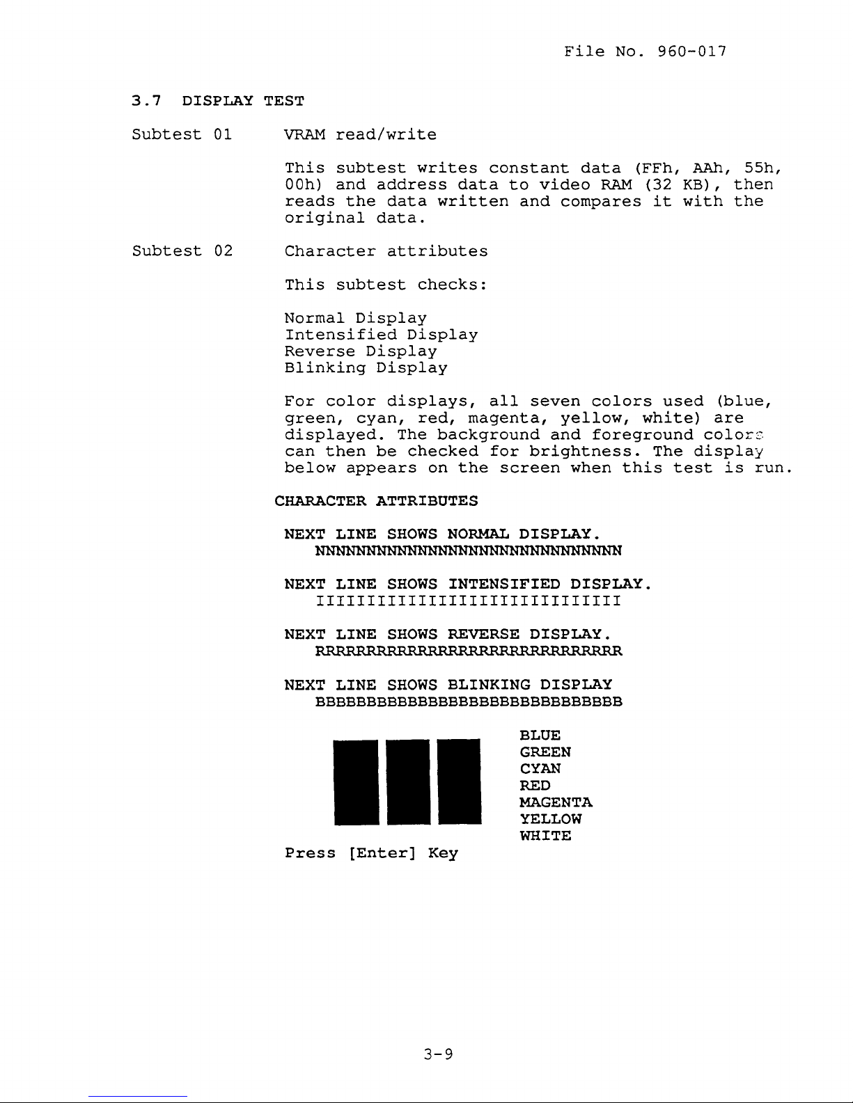
02
Character
This
Normal
Intensified
Reverse
Blinking
For
green,
displayed.
can
below
CHARACTER
read/write
subtest
and
address
the
data.
subtest
Display
Display
Display
color
cyan,
then
be
appears
ATTRIBUTES
writes
data
written
attributes
checks:
Display
displays,
red,
The
background
checked
on
constant
data
all
magenta,
for
the
screen
to
video
and
compares
seven
yellow,
and
brightness.
data
RAM
colors
foreground
when
(FFh,
this
(32
it
used
white)
The
test
AAh,
KB),
with
are
colors
display
55h,
then
the
(blue,
is
run.
NEXT
NEXT
NEXT
NEXT
Press
LINE
LINE
111111111111111111111111111111
LINE
LINE
BBBBBBBBBBBBBBBBBBBBBBBBBBBBBB
SHOWS
SHOWS
SHOWS
SHOWS
[Enter]
NORMAL
INTENSIFIED DISPLAY.
REVERSE
BLINKING DISPLAY
DISPLAY.
DISPLAY.
BLUE
GREEN
CYAN
RED
MAGENTA
YELLOW
WHITE
Key
3-9
File
No.
960-017
Subtest
Subtest
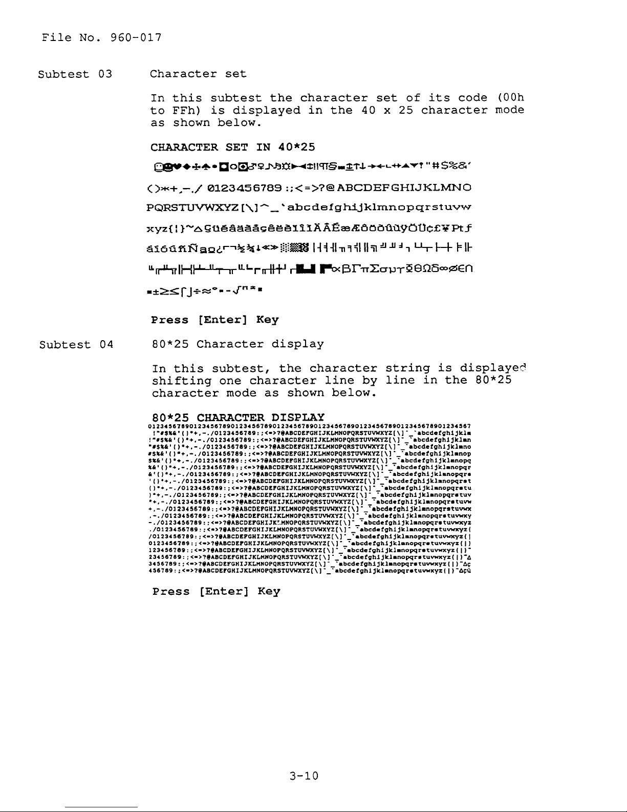
03
04
Character
In
this
to
FFh)
as
shown
CHARACTER
()>+<+~-./
PQRSTUVWXYZ
xyz{
I }
......
6gU~aai!a.9EH:!Ien.11.AA~CBA:e,OOftil9aUC£¥Pt.f
ai6iifiNaQ"r""~~.«»liiiiim
U,rnlHI-'-
Press
80*25
In
this
shifting
character
set
subtest
is
displayed
below.
SET
0123456789
[,\1 --_
liT
II
u.L.rrrtJ+I
[Enter]
Character
subtest,
one
mode
the
character
in
the
IN
40*25
:;<=>?@ABCDEFGHIJKLMNO
'abcdefghijklmnopqrstuvw
H~~I"11'l~III'iI:tI
r&.I
r-o<l3rITLO'l.lT2eOB=¢En
Key
display
the
character
as
character
line
shown
40 x 25
by
below.
set
JJ:I,
string
line
of
its
character
u.-
~
in
code
F
is
displayed
the
(OOh
mode
U-
80*25
80*25
012345618901234567890123456789012345678901234567890123456789012345678901234567
!"".&,,)·+.-./0123456789::<->?@ABCOEFGHI3KLHNOPQRSTUVWXYZ[\]'_'abcdetgh1jkla
!"'$'&',)"+.-./0123456789::<->?@ABCOEFGHI3KLHNOPQRSTUVWXYZ[\]'_'abcdetgh1jklan
"'S.&',)"+.-./0123456789::<->?@ABCOEFGHI3KLHNOPQRSTUVWXYZ[\]'_'abcdetgh1jklano
'S'&',)"+.-./0123456789::<->?@ABCOEFGHI3KLHNOPQRSTUVWXYZ[\]'_'abcdetgh1jklanop
S.&,,)·+.-./0123456789::<->?@ABCOEFGHI3KLHNOPQRSTUVWXYZ[\]'_'abcdetgh1jklanopq
'&")"+.-./0123456789::<->?@ABCDEPGHI3KLHNOPQRSTUVWXYZ[\]·
&'()·+.-./0123456789::<->?IABCOEFGHI3KLHNOPQRSTUVWXYZ[\]·
'()·+.-./0123456789::<->?@ABCDEPGHI3KLHNOPQRSTUVWXYZ[\]·
')·+.-./0123456789::<->?@ABCDEPGHI3KLHNOPQRSTUVWXYZ[\]·_~abcdetgh1jklanopqretu
1·+.-./0123456789::<->?@ABCDEPGHI3KLHNOPQRSTUVWXYZ[\]·_·abcdetgh1jklanopqretuv
"+.-./0123456789::<->?@ABCOEPGHI3KLHNOPQRSTUVWXYZ[\]·_·abcdetgh1jklanopqretuvw
+.-./0123456789::<->?@ABCDEPGHI3KLHNOPQRSTUVWXYZ[\)·
.-./0123456789::<->?@ABCOEFGHI3KLHNOPQRSTUVWXYZ[\]·
-./0123456789::<->?iABCDEFGHI3K~HNOPQRSTUVWXYZ[\]·_~abcdetgh1jklanopqretuvwxyz
./01234S6789::<->?iABCDEFGHI3KLHNOPQRSTUVWXYZ[\]·
/01234S6789::<->?IABCDEPGHI3KLHNOPQRSTUVWXYZ[\]'_~abcdetgh1jklanopqretuvwxyz(1
01234S6789::<->?IABCDEPGHI3KLHNOPQRSTUVWXYZ[\]'_'abcdetgh1jklanopqretuvwxyz(11
123456789::<->?IABCDEPGHI3KLHNOPQRSTUVWXYZ[\]'
23456789::<->?iABCOEPGHI3KLHNOPQRSTUVWXYZ[\]'_~abcdetgh1jklanopqretuvwxyz(II-4
34S6789::<->?iABCOEFGHI3KLHNOPQRSTUVWXYZ[\)'_'abcdetgh1jklanopqretuvwxyz(II-4~
4S6789::<->?iABCDEFGHI3KLHNOPQRSTUVWXYZ[\)'_'abcdetgh1jklanopqretuvwxyz(II-4~U
Press
CHARACTER
[Enter]
Key
DISPLAY
'abcdetgh1jklanopqr
~abcdetgh1jkl.nopqre
~abcdetgh1jklanopqr.t
·abcdetgh1jklanopqr.tuvwx
~abcdetgh1jklanopqretuvwxy
'abcdetgh1jklanopqrstuvwxyz(
'abcdetgh1jklanopqretuvwxyz(ll-
3-10
File
No.
960-017
Subtest
Subtest
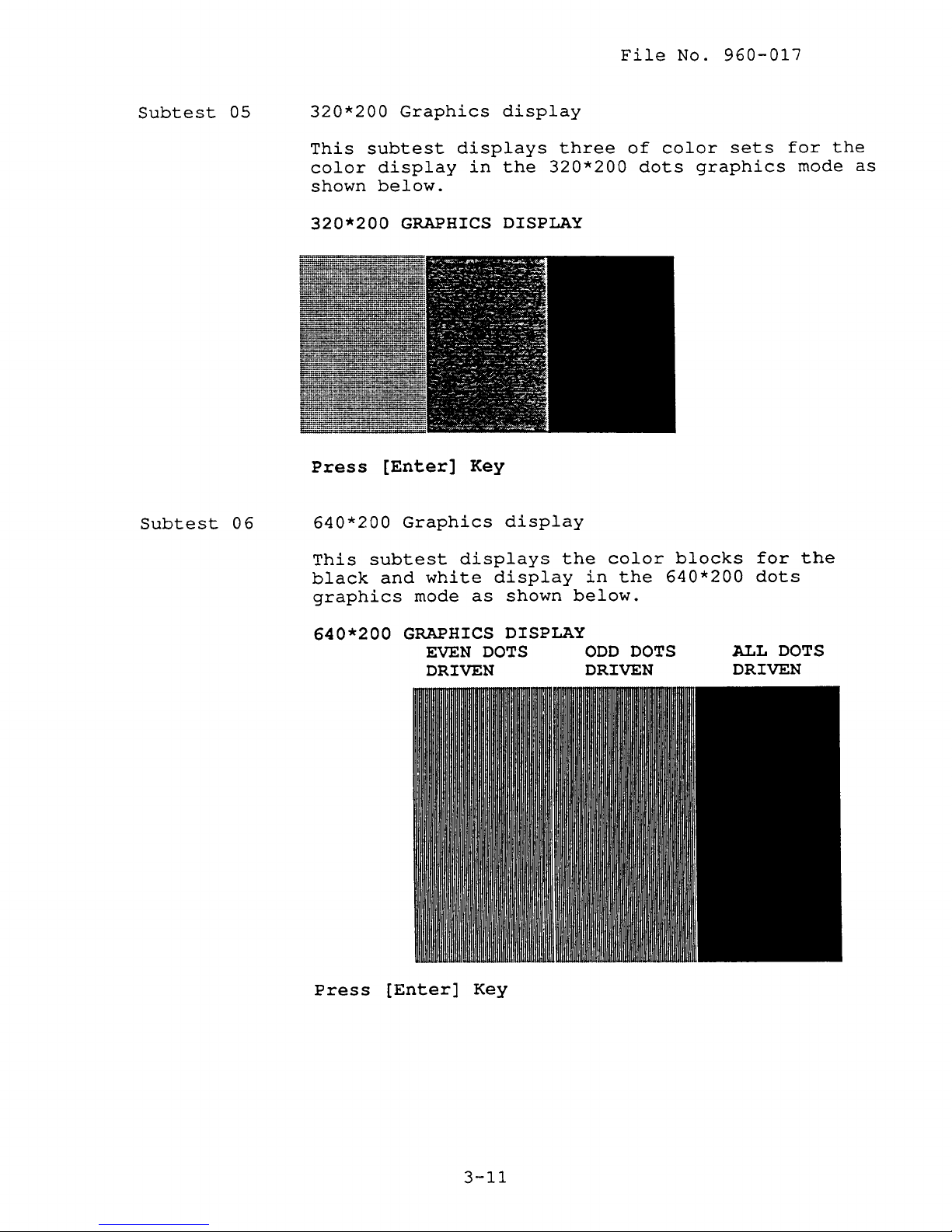
05
06
320*200
This
subtest
color
shown
320*200
Press
640*200
This
subtest
black
graphics
Graphics
display
below.
GRAPHICS
[Enter]
Graphics
and
white
mode
display
displays
in
the
DISPLAY
Key
display
displays
display
as
shown
three
320*200
the
color
in
below.
of
the
color
dots
blocks
640*200
sets
graphics
for
dots
for
mode
the
the
as
640*200
Press
GRAPHICS
EVEN
DRIVEN
[Enter]
DISPLAY
DOTS
Key
ODD
DOTS
DRIVEN
ALL
DOTS
DRIVEN
3-11
File
No.
960-017
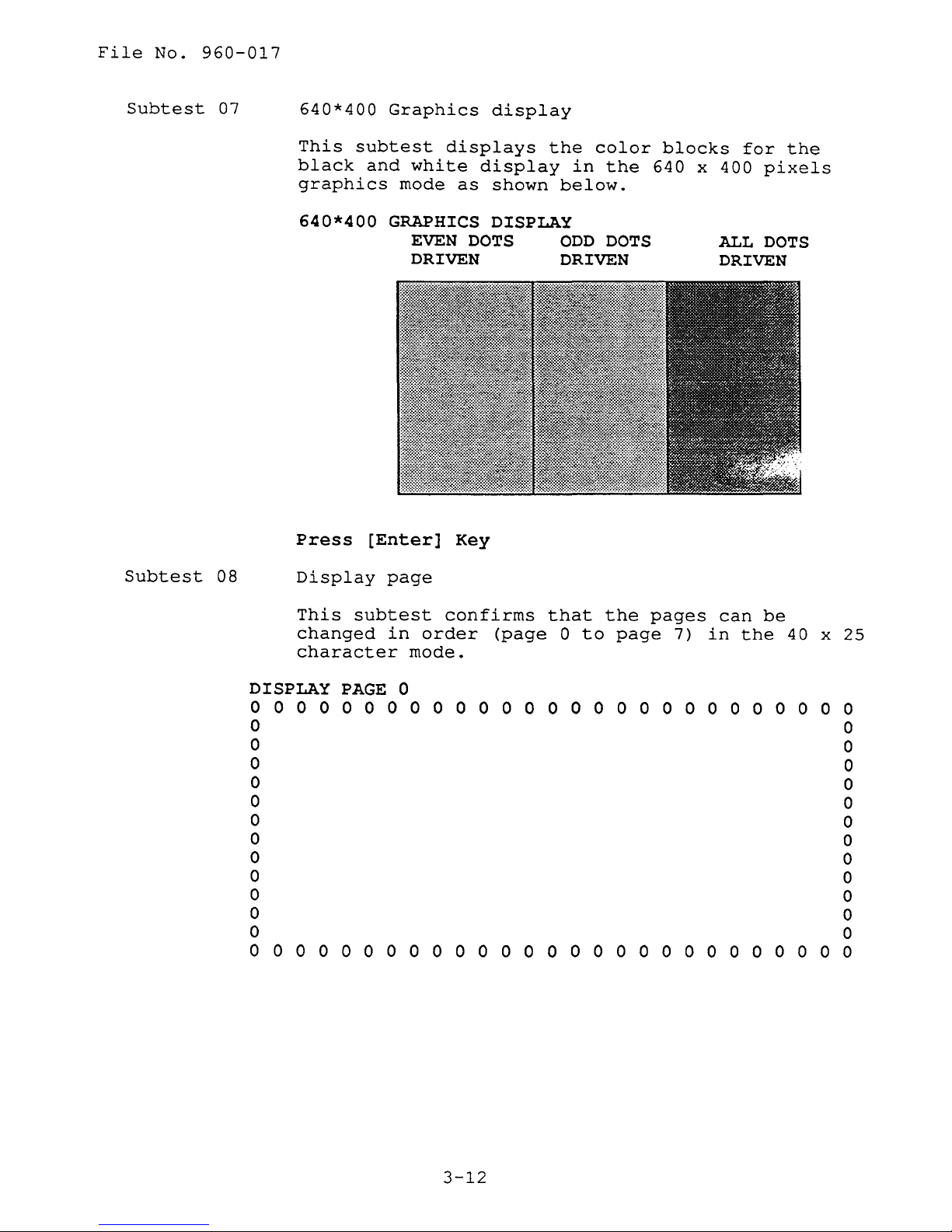
Subtest
07
640*400
This
black
graphics
640*400
Press
subtest
Graphics
displays
and
white
mode
GRAPHICS
EVEN
DRIVEN DRIVEN
[Enter]
display
display
as
shown
DISPLAY
DOTS
Key
the
in
below.
ODD
color
the
DOTS
blocks
640
x
400
ALL
DRIVEN
for
the
pixels
DOTS
Subtest
08
DISPLAY
Display
This
changed
character
subtest
PAGE
page
in
mode.
0
confirms
order
that
(page
o 0 0 0 0 0 0 0 0 0 0 0 0 0
0
000
to
the
pages
page
0 0 0 0 0 0 0 0 0 0
7)
in
can
be
the
o 0
o 0
o 0
o 0
o 0
o 0
o 0
o 0
o 0
o 0
o 0
o 0
o 0 0 0 0 0 0 0 0 0 0 0 0 0 0 0 0 0 0 0 0 0 0 0 0 0 0
40
x
25
3-12
 Loading...