

Toshiba t1000 Installation And Operation Manual
UNINTERRUPTIBLE POWER SYSTEM (UPS)
T1000 Series
UPS INSTALLATION AND OPERATION
MANUAL
SINGLE PHASE - 6 KVA
Rackmount
Conguration
Part # 91074-002
July 2015
Manufactured in the USA
© Copyright 2015 TOSHIBA International Corporation
All rights reserved.
Tower
Conguration

b
T1000 Series UPS Installation and Operation Manual – 91074-002

Product Use and Warranty Restrictions
The Toshiba products listed in this document are intended for usage in general electronics applications
(computer, personal equipment, ofce equipment, measuring equipment, industrial robotics, domestic
appliances, etc.). These Toshiba products are neither intended nor warranted for usage in equipment that
requires extraordinarily high quality and/or reliability or where a malfunction or failure may cause loss
of human life or bodily injury (Unintended Usage). Unintended Usage includes atomic energy control
instruments, airplane or spaceship instruments, transportation instruments, trafc signal instruments,
combustion control instruments, life-support equipment, all types of safety devices, etc. Unintended Usage
of Toshiba products listed in this document shall be made at the customer’s own risk.
NOTICE
PLEASE INFORM A TOSHIBA INTERNATIONAL CORPORATION REPRESENTATIVE IN
CASE OF INCONSISTENCIES, OMISSIONS, OR QUESTIONS.
The instructions contained in this manual are not intended to cover all of the details or variations in
equipment, or to provide for every possible contingency concerning installation, operation, or maintenance.
Should further information be required or if problems arise which are not covered sufciently, contact your
Toshiba sales ofce.
The contents of this instruction manual shall not become a part of or modify any prior or existing agreement,
commitment, or relationship. The sales contract contains the entire obligation of Toshiba International
Corporation/Social Infrastructure Systems Group/Power Electronics Division/UPS Business Unit, hereafter
referred to as Toshiba UPS. The warranty contained in the contract between the parties is the sole warranty
of Toshiba UPS and any statements contained herein DO NOT create new warranties or modify the existing
warranty.
Any electrical or mechanical modications to this equipment without prior written consent of Toshiba UPS
will void all warranties and may void the UL/CUL listing. Unauthorized modications can also result in
personal injury, loss of life, or destruction of the equipment.
QUALIFIED PERSONNEL ONLY
Qualied Personnel are those who have the skills and knowledge relating to the construction,
installation, operation, and maintenance of the electrical equipment and have received safety
training on the hazards involved (Refer to the latest edition of NFPA 70E for additional safety
requirements).
T1000 Series UPS Installation and Operation Manual – 91074-002

UNINTERRUPTIBLE POWER SYSTEM (UPS)
Please complete the following information and retain for your records.
Unless otherwise specied, the warranty period for the UPS or UPS part is 36 months from the shipment
date (see Toshiba International Corporation bill of lading).
Unless otherwise specied, the warranty period for a UPS battery is 24 months from the shipment date (see
Toshiba International Corporation bill of lading).
JOB NUMBER
MODEL NUMBER
SERIAL NUMBER
APPLICATION
SHIPMENT DATE
INSTALLATION DATE
INSPECTED BY
T1000 Series UPS Installation and Operation Manual – 91074-002

Purpose
This manual provides information on how to safely install your Toshiba International Corporation power
electronics product. This manual includes a section of general safety instructions that describes the warning
labels and symbols that are used throughout the manual. Read the manual completely before installing,
operating, or performing maintenance on this equipment.
This manual and the accompanying drawings should be considered a permanent part of the equipment and
should be readily available for reference and review. Dimensions shown in the manual are in metric and/or
the English customary equivalent.
Toshiba International Corporation reserves the right, without prior notice, to update information, make
product changes, or discontinue any product or service identied in this publication.
Toshiba is a registered trademark of the Toshiba Corporation. All other product or trade references appearing
in this manual are registered trademarks of their respective owners.
Toshiba International Corporation shall not be liable for direct, indirect, special, or consequential damages
resulting from the use of the information contained within this manual.
This manual is copyrighted. No part of this manual may be photocopied or reproduced in any form without
the prior written consent of Toshiba International Corporation.
© Copyright 2015 Toshiba International Corporation
All rights reserved.
Printed in the U.S.A.
Toshiba Customer Support Center
Contact the Toshiba Customer Support Center for assistance with application information or for any
problems that you may experience with your Uninterruptible Power System (UPS).
Toshiba Customer Support Center
8 a.m. to 5 p.m. (CST) – Monday through Friday
USA Toll Free (877) 867-8773 – Field Service Tech Support
USA Toll Free (855) 803-7087 – Pre-sales Application Support
Fax (713) 896-5212
Email: ToshibaUPS@tic.toshiba.com
You may also contact Toshiba by writing to:
TOSHIBA INTERNATIONAL CORPORATION
SOCIAL INFRASTRUCTURE SYSTEMS GROUP
POWER ELECTRONICS DIVISION - UPS
13131 West Little York Road
Houston, Texas 77041-9990
Attn: T1000 Product Manager
For further information on Toshiba products and services, please visit our website at:
www.toshiba.com/tic/industrial/uninterruptible-power-systems
T1000 Series UPS Installation and Operation Manual – 91074-002

This page intentionally left blank.
f
T1000 Series UPS Installation and Operation Manual – 91074-002

Table of Contents
1. General Safety Instructions ........................................................................1
1.1 Symbols ............................................................................................1
1.2 Signal Words ....................................................................................2
1.3 Regulatory Compliance Statement ...................................................2
2. Equipment Warning Labels ........................................................................3
3. Important Safety Instructions .....................................................................5
3.1 Qualied Personnel Only ..................................................................6
4. Inspection/Storage/Disposal ......................................................................7
4.1 Inspection .........................................................................................7
4.2 Unpacking .........................................................................................7
4.3 Storage .............................................................................................7
4.4 Disposal ............................................................................................7
5. Installation Precautions ..............................................................................8
5.1 Conductor Routing and Grounding ...................................................9
6. Installation....................................................................................................10
6.1 Module Arrangement ........................................................................10
6.2 System Installation............................................................................11
6.3 Tower Installation with Cap ...............................................................12
6.4 Rackmount Installation - Bracket Mounting Holes ............................13
6.5 4-Post Rack Installation Instructions ................................................13
7. Wiring the System .......................................................................................16
7.1 Layout - Power Module ....................................................................16
7.2 Layout - Battery Module (w/ Outlet Panel) .......................................17
7.3 Layout - Transformer Module ...........................................................18
7.4 Power Module Cable Size and Tightening Torque ............................ 18
8. Operating Precautions ................................................................................21
9. Control Panel ...............................................................................................22
9.1 Control Panel Layout ........................................................................22
9.2 Light Emitting Diodes (LED) .............................................................23
9.3 LCD Display - Open the Main Menu .................................................23
9.4 LCD Display - Menu/Sub-Menu Navigation ......................................24
9.5 LCD Display - Sub-Menu/Parameter Navigation ..............................25
10. UPS Operation ...........................................................................................26
10.1 Initial Startup .................................................................................26
10.2 Startup (Normal) ...........................................................................27
10.3 Bypass ..........................................................................................27
10.4 Shutdown ......................................................................................28
T1000 Series UPS Installation and Operation Manual – 91074-002
i

11. System Description ...................................................................................29
11.1 Application and Use ........................................................................29
11.2 Power Backup ................................................................................. 29
11.3 Power Conditioning ......................................................................... 29
12. Operating Modes .......................................................................................30
12.1 Static-Bypass (Stop operation) .......................................................30
12.2 On-Line (Run operation) ...............................................................30
12.3 Battery Backup (On batteries) ........................................................31
12.4 EPO (Emergency Power Off) Function ...........................................31
12.5 Cold Start (On Batteries) ................................................................32
12.6 Frequency Conversion Mode (CVCF) ............................................32
12.7 Battery Backup Time and Discharge Process ..............................33
12.8 Battery Low Voltage Tolerances .....................................................33
12.9 Battery Recharging .........................................................................34
12.10 Battery Test ................................................................................... 35
13. Control Panel Menu Trees ........................................................................36
13.1 Control Panel Navigation and Menu Access...................................36
13.2 Top Menu - Sub-Menu Tree ............................................................37
13.3 Monitor Sub-Menu/Parameter Tree ................................................38
13.4 Setting Sub-Menu/Parameter Tree .................................................39
13.5 Records Sub-Menu/Parameter Tree ...............................................40
14. Operation....................................................................................................41
14.1 Cold Start ........................................................................................41
14.2 EPO and Remote Stop ...................................................................41
15. Communication Interfaces .......................................................................43
15.1 Remote Contacts ............................................................................43
15.2 (Optional) RemotEye® Network Card ..............................................44
15.3 (Optional) Google ChromeTM Browser App ..................................... 45
15.4 (Optional) EMD ...............................................................................46
16. UPS Protection System.............................................................................47
16.1 UPS Protection Devices .................................................................47
16.2 UPS Protection Devices Fault Response ......................................47
16.3 System Fault Messages .................................................................49
16.4 System Warning Messages ............................................................50
16.5 System Mode Messages ................................................................52
16.6 System Status Messages ...............................................................53
17. Preventive Maintenance/Parts Replacement ..........................................54
17.1 Preventive Maintenance .................................................................54
17.2 LCD Display Cleaning.....................................................................54
17.3 Battery Replacement ....................................................................54
ii
T1000 Series UPS Installation and Operation Manual – 91074-002

17.4 Part Replacement ...........................................................................54
18. Shipping Weights/Dimensions .................................................................55
18.1 Unit and Shipping Weights .............................................................55
18.2 Shipping Dimensions .....................................................................55
Appendix A: T1000 Specications .................................................................A-1
Appendix B: T1000 Menu Table ......................................................................B-1
Appendix C: T1000 Dimensional Drawings...................................................C-1
Appendix D: T1000 Packing Lists and Kit Contents ....................................D-1
Inter-Module Cabling Identication ..........................................................D-1
Appendix E: T1000 Optional Installation Kit Instructions ...........................E-1
E.1 Optional 3-Module Tower Cap Kit - 93178 .......................................E-1
E.2 Optional Tower Caster Kit - 90508 ...................................................E-2
E.3 Optional T1000 2-Post Rack Fixed Installation Kit - 92801 ..............E-5
E.4 Optional T1000 4-Post Rack Slide Installation Kit - 92800 ...............E-8
E.5 Optional T1000 2-Post Rack Slide Installation Kit - 90400 ...............E-11
Index ..................................................................................................................I-1
T1000 Series UPS Installation and Operation Manual – 91074-002
iii

This page intentionally left blank.
iv
T1000 Series UPS Installation and Operation Manual – 91074-002
1. General Safety Instructions
DO NOT attempt to transport, install, operate, maintain or dispose of this equipment until you have read and
understood all of the product safety information provided in this manual.
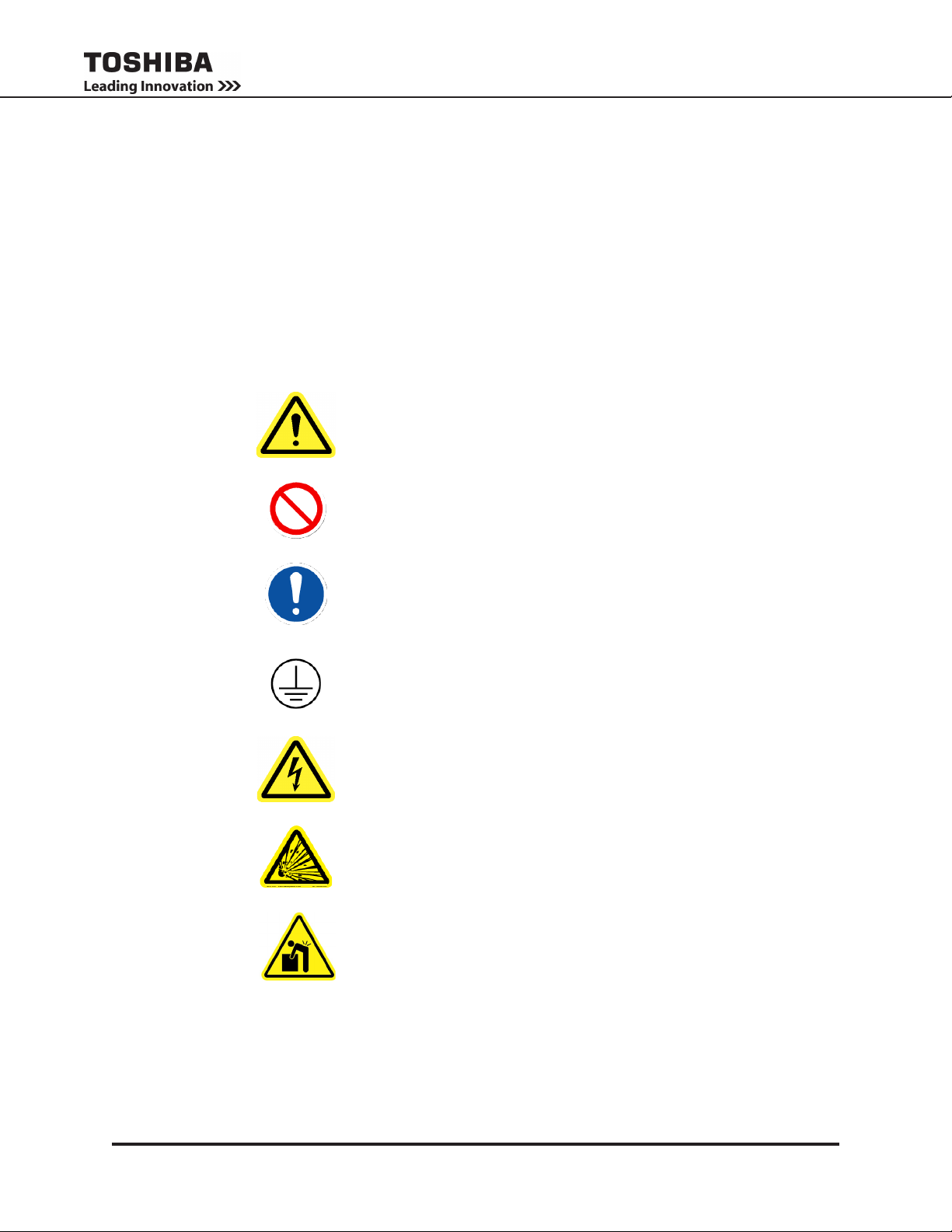
1.1 Symbols
The symbols listed below are used throughout this manual. When symbols are used in this manual they will
include important safety information that must be carefully followed.
Safety Alert Symbol indicates that a potential
personal injury hazard exists.
Prohibited Symbol indicates DO NOT take action.
Mandatory Symbol indicates that the following
instruction is required.
Ground Symbol indicates the location of the
equipment grounding conductor.
Electrical – Voltage & Shock Hazard Symbol
indicates parts inside may cause electric shock.
Explosion Hazard Symbol indicates parts may
explode.
Heavy Lift Hazard Symbol indicates object
requires two- or more man lift, or lifting aid.
T1000 Series UPS Installation and Operation Manual – 91074-002
1

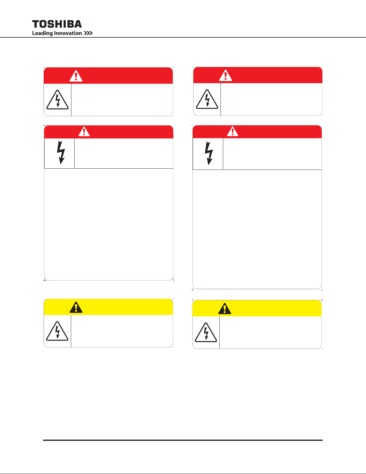
1.2 Signal Words
The signal words listed below are used throughout this manual. When the words DANGER, WARNING,
CAUTION and NOTICE are used in this manual they will include important safety information that must be
carefully followed.
The word DANGER in capital letters preceded by
DANGER
WARNING
CAUTION
the safety alert symbol indicates that an imminently
hazardous situation exists, and if not avoided
will result in loss of life or serious injury to
personnel.
The word WARNING in capital letters preceded by
the safety alert symbol indicates that a potentially
hazardous situation exists, and if not avoided
may result in loss of life or serious injury to
personnel.
The word CAUTION in capital letters preceded by
the safety alert symbol indicates that a potentially
hazardous situation exists, and if not avoided may
result in minor or moderate injury.
The word NOTICE in capital letters without the safety
NOTICE
alert symbol indicates a potentially hazardous
situation exists, and if not avoided may result in
equipment and property damage.
1.3 Regulatory Compliance Statement
FCC Class A Notice
This equipment has been tested and found to comply with the limits for a Class A digital device, pursuant
to Part 15 of the FCC Rules. These limits are designed to provide reasonable protection against harmful
interference when the equipment is operated in a commercial environment. This equipment generates,
uses, and can radiate radio frequency energy, and if it is not installed and used in accordance with the
instruction manual, it may cause harmful interference to radio communications. Operation of this equipment
in a residential area is likely to cause harmful interference, in which case the user will be required to correct
the interference at his own expense.
This device complies with Part 15 of the FCC Rules. Operation is subject to the following two conditions:
1. This device may not cause harmful interference.
2. This device must accept any interference received, including interference that may cause undesired
operation.
Notice: The FCC regulations provide that changes or modications made to this device that are not
approved by Toshiba International Corporation may void the authority granted to the user by the FCC to
operate this equipment.
EMC Directive Class A Note
This UPS is commercial in design and not intended for use at anytime in a Residential Environment.
2
T1000 Series UPS Installation and Operation Manual – 91074-002

2. Equipment Warning Labels
WARNING AREA
TEXT AREA
WARNING AREA
TEXT AREA
WARNING AREA
TEXT AREA
WARNING AREA
TEXT AREA
WARNING AREA
TEXT AREA
WARNING AREA
TEXT AREA
The following pages show examples of warning labels that may be attached to either the interior or exterior
of the Power (UPS), Battery, or Transformer Modules. Do not remove or cover any of the labels. If the
labels are damaged or if additional labels are required, contact your equipment representative for additional
labels.
These labels in both English and French are placed to provide useful information or to indicate an imminently hazardous situation that may result in severe equipment/property damage, serious injury, or loss of
life if instructions are not followed.
LABELS IN ENGLISH ÉTIQUETTES EN FRANÇAIS
DANGER
AC VOLTAGE
This UPS receives power from more
than one source. Disconnect all AC
sources before performing any service
or testing inside this unit
48082
DANGER
RISK OF ELECTRIC SHOCK
Capacitors stay charged after power
has been shut off.
Accidental contact with live parts can
cause personal injury and death.
Turn off and lock out all power sources.
WAIT AT LEAST FIVE (5) MINUTES
for power to dissipate, then check
voltage before servicing.
57275
DANGER
DC VOLTAGE
DC Voltage supplied by batteries is still
present after equipment has been
turned off and taken off line.
Accidental contact with live parts can
cause personal injury and death.
Disconnect all DC Sources before
performing any service or testing
in this compartment.
43784
DANGER
TENSION AC
Cette UPS est alimentée par plus d´une
source. Débrancher toutes les sources
AC avant d´effectuer des entretiens ou
des tests à l´intérieur de cette unité.
90630
DANGER
RISQUE DE CHOC ÉLECTRIQUE
Les condensateurs restent chargés après
coupure de l´alimentation. Tout contact
accidental avec des composants sous
tension électrique peut provoquer des
blessures ou la mort. Fermer et verrouiller
toutes les sources d´alimentation.
ATTENDRE AU MOINS (5) MINUTES
pour laisser décharger les condensateurs,
puis vérifier la tension électrique avant
l´entretien.
90624
DANGER
TENSION DC
Tension DC fournie par des batteries
est encore présente après que le
matériel a été éteint et mis hors linge.
Tout contact accidentel avec des
composants sous tension peut causer
des blessures et la mort.
Débrancher toutes les sources DC
avant d´effectuer des réparations ou
des tests dans ce compartiment.
90632
FIGURE 2-1: EQUIPMENT WARNING LABELS
T1000 Series UPS Installation and Operation Manual – 91074-002
3
0.75"
2.00"
0.75"
2.00"
WARNING AREA
TEXT AREA
WARNING AREA
TEXT AREA
0.75"
2.00"
0.75"
2.00"
LABELS IN ENGLISH ÉTIQUETTES EN FRANÇAIS
DANGER
Risk of electrical shock.
Live terminals on batteries.
Do not touch uninsulated battery
terminal.
PN 40759
DANGER
HAZARDOUS VOLTAGES
Hazardous voltages are used in the operation
of this equipment and could cause severe personal
injury or loss of life.
The following precautions should be observed to
reduce the risk of injury or death.
Only qualified technicians familiar with this equipment and the
information supplied with it should be permitted to install and
operate this equipment.
Installation of electrical equipment must be done in
accordance with National Electrical Code and any other state
or local codes. Proper grounding and conductor sizing must
be installed for safe operation.
During operation, keep all covers in place and cabinet
doors shut.
When performing visual inspections and maintenance, if
possible, be sure the UPS is turned off and the incoming
AC feed is turned off and locked out.
The UPS and Battery Cabinet will have hazardous
voltages present even after the AC feed is turned off.
If it is necessary to make measurements with the power
on, do not touch any electrical connection points. Remove
all jewelry from wrists and fingers. Make sure test equipment
is in good, safe operating condition.
While servicing, stand on some type of insulation, and be
sure not to be grounded.
Follow the safety instructions given in the equipment manual
carefully and observe all danger, warning and caution notices.
40308
DANGER
Risque de choc électrique.
Bornes de batteries sous tension.
Ne pas toucher de borne de batterie non
isolée.
PN 90637
DANGER
TENSIONS DANGEREUSES
Des tensions dangereuses sont utilisées dans
l´opération de cet appareil et pourraient causer
des blessures graves ou des pertes de vie.
Les mesures de sécurité suivantes doivent être
observées pour réduire le risque de blessure ou de
Seulement des techniciens qualifiés et familiarisés avec ce
matériel, ainsi que la documentation fournie avec elle,
devraient être autorisés à installer et à utiliser cet équipement.
L´installation de l´équipement électrique doit être effectuée
selon les normes électriques reconnues par les organismes
nationaux ou provinciaux accrédités. Une bonne mise à la
terre et un calibre de câble approprié doivent être installés
pour un fonctionnement sécuritaire.
Pendant le fonctionnement, maintenir tous les couvercles en
place et les portes de l´armoire fermées.
Lors des inspections visuelles et d´entretien, si possible,
vérifier que l´UPS soit éteinte et que l´alimentation AC est
éteninte et verrouillée.
L´UPS et l´armoire de batterie auront des tensions
dangereuses présentes même après avoir coupé
l´alimentation AC.
Si des mesures sur l´appareil sous tension doivent être
effectuées, ne toucher à aucun point de connexion
électrique. Retirer tous les bijoux des poignets et des doigts.
S´assurer que l´équipement de test est en bon êtat de
fonctionnement.
.
Lors des opérations de maintenance, l´opérateur doit se tenir
sur une surface isolée non reliée à la mise à la terre.
Suivre attentivement les consignes de sécurité indiquées
dans le manuel d´opération et respecter tous les avis de
danger, les avertissements et les mises en garde.
mort.
90638
CAUTION
Risk of electrical shock.
Battery circuit is not isolated from AC input,
hazardous voltage may exist between
battery terminals and ground.
Test circuit before touching.
PN 40760
ATTENTION
Risque de choc électrique.
Le circuit de la batterie n´est pas isolé de
l´entrée AC, des tensions dangereuses
peuvent exister entre les bornes de la
batterie et la masse.
Tester le circuit avant de toucher.
PN 90636
FIGURE 2-1: (CONT.) EQUIPMENT WARNING LABELS
4
T1000 Series UPS Installation and Operation Manual – 91074-002
3. Important Safety Instructions
This manual contains important instructions that should be followed during the installation and maintenance
of the UPS and its batteries.
The T1000 Series UPS is a modular single-phase double conversion system. Each of the rackmount
modules is 3U (Three Standard Rack Units) high.
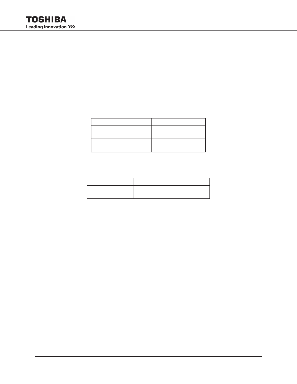
UPS systems are not equipped with an over-current protection device nor an output disconnect for the AC
output. Circuit breakers should be provided by the user between the UPS Input and utility power, and the
UPS output and the load input. This device should be rated as follows:
240/208 VAC RATING* 6 kVA
Input Breaker
240 V / 208 V 40 A
Output Breaker
240V / 208V 40 A
* Ratings are for a 80% rated device.
The nominal battery voltages for these models is as follows:
UNIT BATTERY VOLTAGE
6 kVA
Servicing the batteries should only be performed by a qualied factory authorized representative who is
knowledgeable about batteries and the required precautions. Keep unauthorized personnel away from
batteries. To arrange for battery replacement, contact Toshiba Customer Support Center.
1. Turn off, lockout, and tagout all equipment before connecting the power wiring to the equipment or
when performing maintenance.
2. The maximum ambient operating temperature is 104 °F (40 °C). UPS will go to Bypass when it
overheats.
3. Access panels should only be removed by authorized Toshiba eld Service personnel.
4. UPS servicing should be performed by qualied Toshiba representatives only.
5. Battery servicing should be performed by qualied Toshiba representatives only.
6. Contact your Toshiba authorized service center for battery replacement.
216 Vdc (Nominal)
(1 string of 18 x 12V batteries)
T1000 Series UPS Installation and Operation Manual – 91074-002
5
3.1 Qualied Personnel Only
Qualied personnel are those who have the skills and knowledge relating to the construction,
installation, operation, and maintenance of the electrical equipment and have received safety
training on the hazards involved (Refer to the latest edition of NFPA 70E for additional safety
requirements).
Qualied personnel shall:
1. Have read the entire operation manual.
2. Be trained and authorized to safely energize, de-energize, ground, lockout and tag circuits
and equipment, and clear faults in accordance with established safety practices.
3. Be trained in the proper care and use of protective equipment such as safety shoes, rubber
gloves, hard hats, safety glasses, face shields, ash clothing, etc., in accordance with
established safety practices.
4. Be trained in rendering rst aid.
5. Be knowledgeable about batteries and their required handling and maintenance precautions.
For further information about workplace safety visit www.osha.gov.
Misuse of this equipment may result in human injury
CAUTION
and equipment damage. In no event will Toshiba
Corporation be responsible or liable for either
indirect or consequential damage or injury that may
result from the misuse of this equipment.
CAUTION
CAUTION
To be performed by Qualied Personnel Only:
DO NOT open or mutilate the batteries. Released
electrolyte is harmful to the eyes and skin and could
also be toxic.
DO NOT dispose of the battery module in
a re. The batteries inside may explode.
1. Verify that the UPS is off and that the power is disconnected from the power source.
2. Remove watches, rings or other metal objects.
3. Use tools with insulated handles to prevent inadvertent shorts.
4. Wear rubber safety gloves and boots.
5. DO NOT place tools or any metal parts on top of batteries.
6. Determine if the battery is inadvertently grounded. If inadvertently grounded, remove source of
ground.
WARNING
Contact with any part of a grounded battery can result in
electrical shock.
The likelihood of shock will be reduced if such grounds are removed
prior to installation or maintenance.
6
T1000 Series UPS Installation and Operation Manual – 91074-002

4. Inspection/Storage/Disposal
4.1 Inspection
Inspect for shipping damage upon receipt of the UPS. Use caution when removing the unit from the pallet.
Refer to labels or documentation attached to packing material.
4.2 Unpacking
Check the unit for loose, broken, bent or otherwise damaged parts. If damage has occurred during shipping,
keep all original crating and packing materials for return to the shipping agent. The warranty does not apply
to damage incurred during shipping. Ensure that the rated capacity and the model number specied on the
nameplate conform to the order specications.
4.3 Storage
During periods of non-use, the following guidelines are recommended for storage.
Storage Preparation
1. Power up the UPS and allow it to operate with no load for 24 hours to fully charge the
batteries.
2. Stop the unit (See Section 12.1 Bypass/Stop Operation).
3. Place the MCCB switch (Fig. 7-1 (1)) in the Off position.
Storing Conditions
• For best results, store the UPS in the original shipping container and place on a wood
or metal pallet.
• Storage temperature: -4 – 104 °F (-20 – 40 °C).
• The optimum storage temperature is 70 °F (21 °C). A higher ambient temperature will
require recharging more frequently during storage.
Avoid storage locations that:
• Are subject to extreme temperature changes or high humidity.
• Are subject to high levels of dust or metal particles.
• Are subject to excessive vibration.
• Have inclined oor surfaces.
Storage Maintenance
• If stored at an ambient temperature less than 68 °F (20 °C), recharge the batteries every
9 months.
• If stored at an ambient temperature of 68 – 86 °F (20 – 30 °C), recharge the batteries
every 6 months.
• If stored at an ambient temperature of 86 – 104 °F (30 – 40 °C), recharge the batteries
every 3 months.
4.4 Disposal
Contact your local or state environmental agency for details on disposal of electrical components and
packaging in your particular area.
It is illegal to dump lead-acid batteries in landlls or dispose of improperly.
Please help our Earth by contacting the environmental protection agencies in your area, the battery
manufacturer, or call Toshiba toll-free at (877) 867-8773 for more information about recycling.
T1000 Series UPS Installation and Operation Manual – 91074-002
7

5. Installation Precautions
NOTICE
1. Observe the following environmental restrictions:
• Install the unit in a well-ventilated location.
• Install the unit where the ambient temperature is within the range specied in Appendix A -
“Specications”.
• DO NOT install the UPS in areas that are subject to high humidity.
• DO NOT install the UPS in areas that allow exposure to direct sunlight.
• DO NOT install the UPS in areas that allow exposure to high levels of airborne dust, metal
particles, or ammable gases.
• DO NOT install the UPS in areas near sources of electrical noise. Ensuring a proper earth ground
will reduce the effects of electrical noise and will reduce the potential for electrical shock.
• DO NOT install the UPS in areas that would allow uids or any foreign object to get inside the
UPS.
2. Install the unit in a stable, level and upright position that is free of excessive vibration.
3. Follow the instructions on the unpacking label afxed to the exterior of the UPS.
4. Tower Unit with Caster Kit Option Only: Once the installation is complete, screw down the UPS
leveling feet located next to the front and back casters, until the unit is no longer resting on the
casters.
5. The UPS generates and can radiate radio-frequency energy during operation. Although RFI noise
lters are installed inside of the unit, there is no guarantee that the UPS will not inuence some
sensitive devices that are operating near by. If such interference is experienced, the UPS should be
installed farther away from the affected equipment and/or powered from a different source than that
of the affected equipment.
6. It is the responsibility of the installer of this equipment to provide a suitable disconnect for the Control
Panel supplying power to this equipment.
This disconnect must:
Be suitable for the Voltage and Full Load Ampere Rating of all downstream equipment supplied by
the Panel;
The supply disconnecting device shall be one of the following types:
• Switch-disconnect, with or without fuses, in accordance with IEC 60947-3, utilization category
AC-23B or DC-23B
• As above, except one that has an auxiliary contact that in all cases causes switching devices
to break the load circuit before the opening of the main contacts of the disconnect.
• A circuit breaker suitable as an isolation device per IEC 60947-2
• Any other switching device in accordance with an IEC product standard that also meets the
isolation requirements of IEC 60947-1 and is appropriate for on-load switching of motors or
other inductive loads;
Be approved for use as a disconnect for the country in which this equipment is installed.
Be provided with a Lock Out Tag Out capability in the Off (Down) position.
8
T1000 Series UPS Installation and Operation Manual – 91074-002
7. Allow 5 minutes after power is removed for internal capacitors to fully discharge before attempting
to service the unit.
8. The user should provide output over-current protection for hardwired UPS systems. See “Appendix
A: T1000 Specications” on page A-1A-2 for the device rating.
9. After ensuring that all power sources are turned off and isolated in accordance with established
lockout/tagout procedures, connect the power source wiring of the correct voltage to the input
terminals of the UPS.
10. Hardwire Only: Connect the output terminals of the UPS to the load in line with local wiring
regulations. Size the branch circuit conductors in accordance with NEC Table 310.16.
5.1 Conductor Routing and Grounding
1. Use separate metal conduits for routing the input power, output power, and control circuits.
2. Follow the wire size and tightening torque specications listed on Table 7-4.
3. Always ground the unit to reduce the potential for electrical shock and to help reduce electrical
noise.
4. A separate ground cable should be run inside the conduit with the input power, output power, and
control circuits.
WARNING
METAL OF CONDUIT IS NOT AN ACCEPTABLE GROUND.
T1000 Series UPS Installation and Operation Manual – 91074-002
9
6. Installation
6.1 Module Arrangement
The T1000 Series UPS consists of a Power (UPS) module, optional Battery module(s), and optional
Transformer module for output other than 240/208 V. These modules can be purchased in either a rackmount or tower conguration.
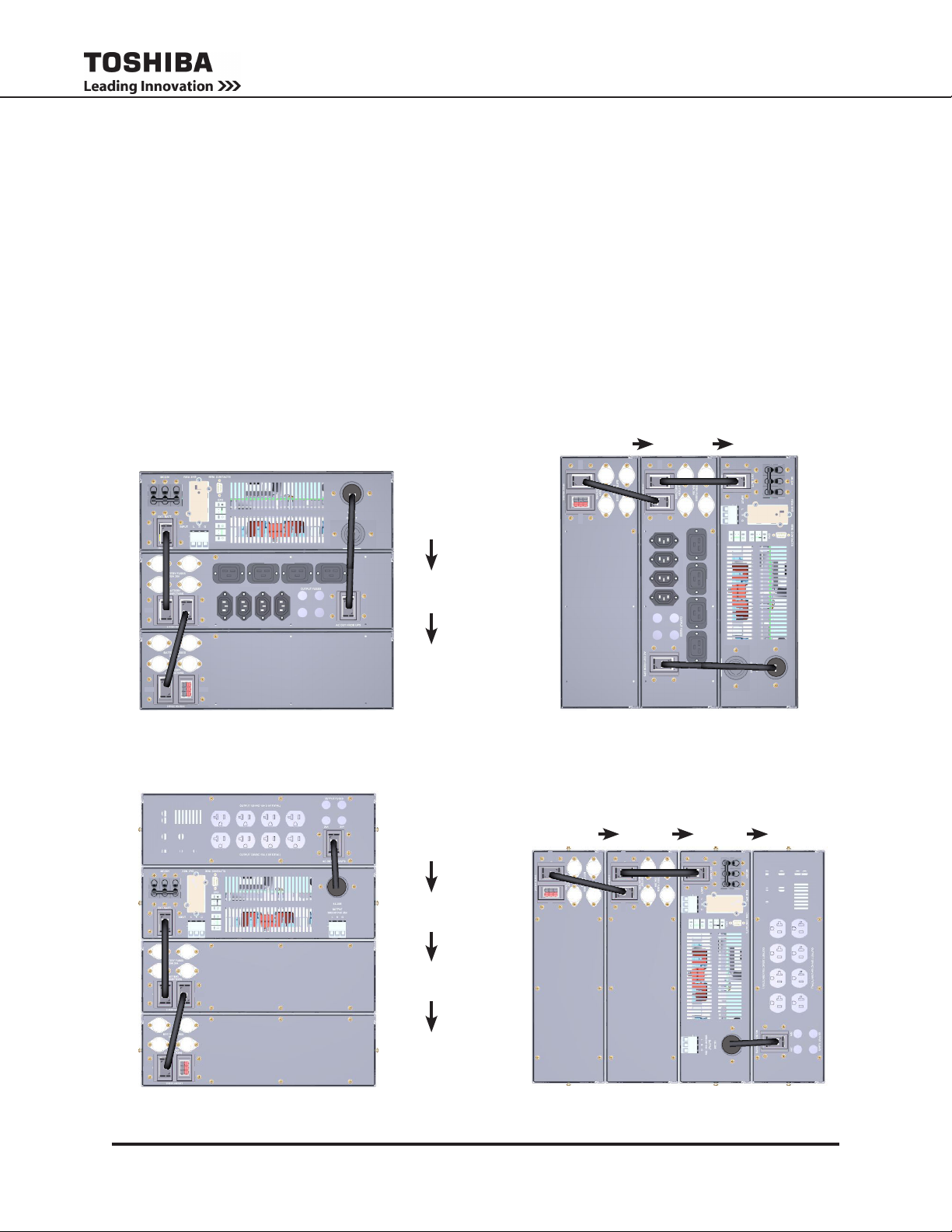
Module arrangement is determined by the length of the factory-supplied inter-module cables. The Modules should be arranged in the following order as viewed from the front: top-to-bottom for Rackmount
(Fig. 6-1, Fig. 6-2); left-to-right for Tower (Fig. 6-3, Fig. 6-4).
NOTE: If a Transformer module is used, then the battery module(s) may, or may not, have an output
panel.
OUTPUT 240VAC 15A
CN12A CN12B
REAR VIEW
CN12A CN12B
OUTPUT 240VAC 10A
10A 15A
10A
15A
FIGURE 6-1: RACKMOUNT 240V
SYSTEM WITH C-13/C-19 PANEL
POWER
MODULE
BATTERY
MODULE 1
BATTERY
MODULE 2
OUT
TRANSFORMER
MODULE
BATTERY
MODULE 2
CN12A CN12B
REAR VIEW
BATTERY
MODULE 1
CN12A CN12B
10A
10A 15A
15A
OUTPUT 240VAC 10A
OUTPUT 240VAC 15A
FIGURE 6-3: TOWER 240V
SYSTEM WITH C-13/C-19 PANEL
BATTERY
MODULE 2
CN12A CN12B
BATTERY
MODULE 1
CN12A CN12B
POWER
MODULE
POWER
MODULE
OUT
TRANSFORMER
MODULE
REAR VIEW
CN12A CN12B
CN12A CN12B
FIGURE 6-2: RACKMOUNT 120V
TEM WITH TRANSFORMER MODULE
10
OUT
SYS-
POWER
MODULE
BATTERY
REAR VIEW
MODULE 1
BATTERY
MODULE 2
FIGURE 6-4: TOWER 120V
WITH TRANSFORMER MODULE
SYSTEM
OUT
T1000 Series UPS Installation and Operation Manual – 91074-002
6.2 System Installation
The T1000 Series Power (UPS) module, optional Battery module(s), and optional Transformer module can
be purchased in either a rackmount or tower conguration. All three modules are a standard 3U (3 Rack
Units) tall, and t a standard 19 in. rack.
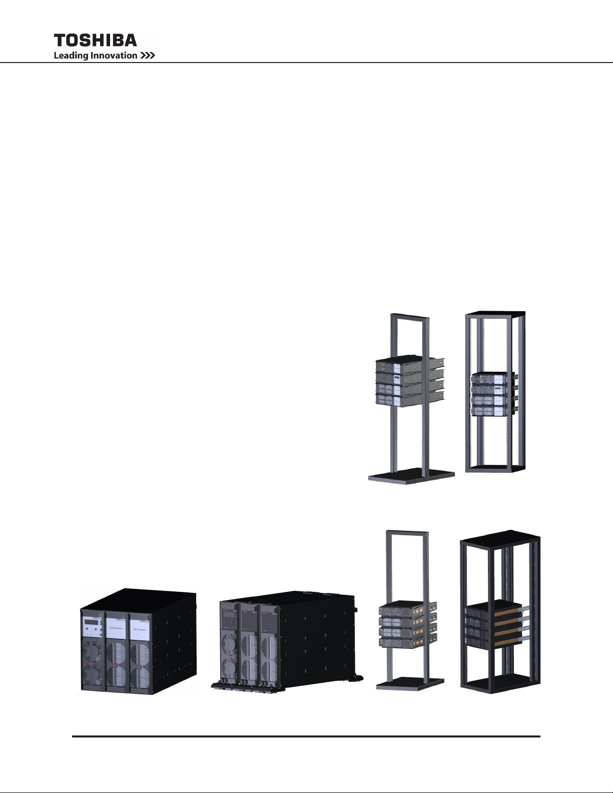
TOWER CONFIGURATION:
In the tower conguration, the orientation of the modules are rotated 90 degrees counter-clockwise,
placing the ventilation openings on the bottom. A slip-on Tower Cap is used to provide physical stability
for systems of two or more tower modules, including tower systems with optional casters. (Figure 6-5)
• OPTIONAL: TOWER CAPS
Each 2-Module tower system comes with a Tower Cap that helps maintain physical tower stability.
Optional 3-Module Tower Caps are available for larger systems.
• OPTIONAL: CASTERS
An optional caster kit may also be purchased with each module to facilitate relocating the system
before and after installation.
RACKMOUNT CONFIGURATION:
Each rackmount conguration module ships with a 4-Post
Rack Fixed Mounting Kit, P/N 92802, for mounting the
module in a standard 19 inch rack.
Other rack mounting kit congurations are available: (Fig-
ure 6-6)
• OPTIONAL: 2-POST RACK FIXED MOUNTING KIT
Hardware for mounting system modules in a standard
19 inch 2-post rack. See Appendix E.
• OPTIONAL: 4-POST RACK SLIDE MOUNTING KIT
Hardware for mounting system modules in a standard
19 inch 4-post rack with fully extending slide rails. See
Appendix E.
• OPTIONAL: 2-POST RACK SLIDE MOUNTING KIT
Hardware for mounting system modules in a standard
19 inch 2-post rack with fully extending slide rails. See
Appendix E.
2-POST RACK
FIXED INST.
2-POST RACK
WITH SLIDES
4-POST RACK
FIXED INST.
4-POST RACK
WITH SLIDES
TOWER WITH CAP
FIGURE 6-5: TOWER
INSTALLATION OPTIONS
T1000 Series UPS Installation and Operation Manual – 91074-002
TOWER WITH CAP AND CASTERS
FIGURE 6-6: RACK
INSTALLATION OPTIONS
11
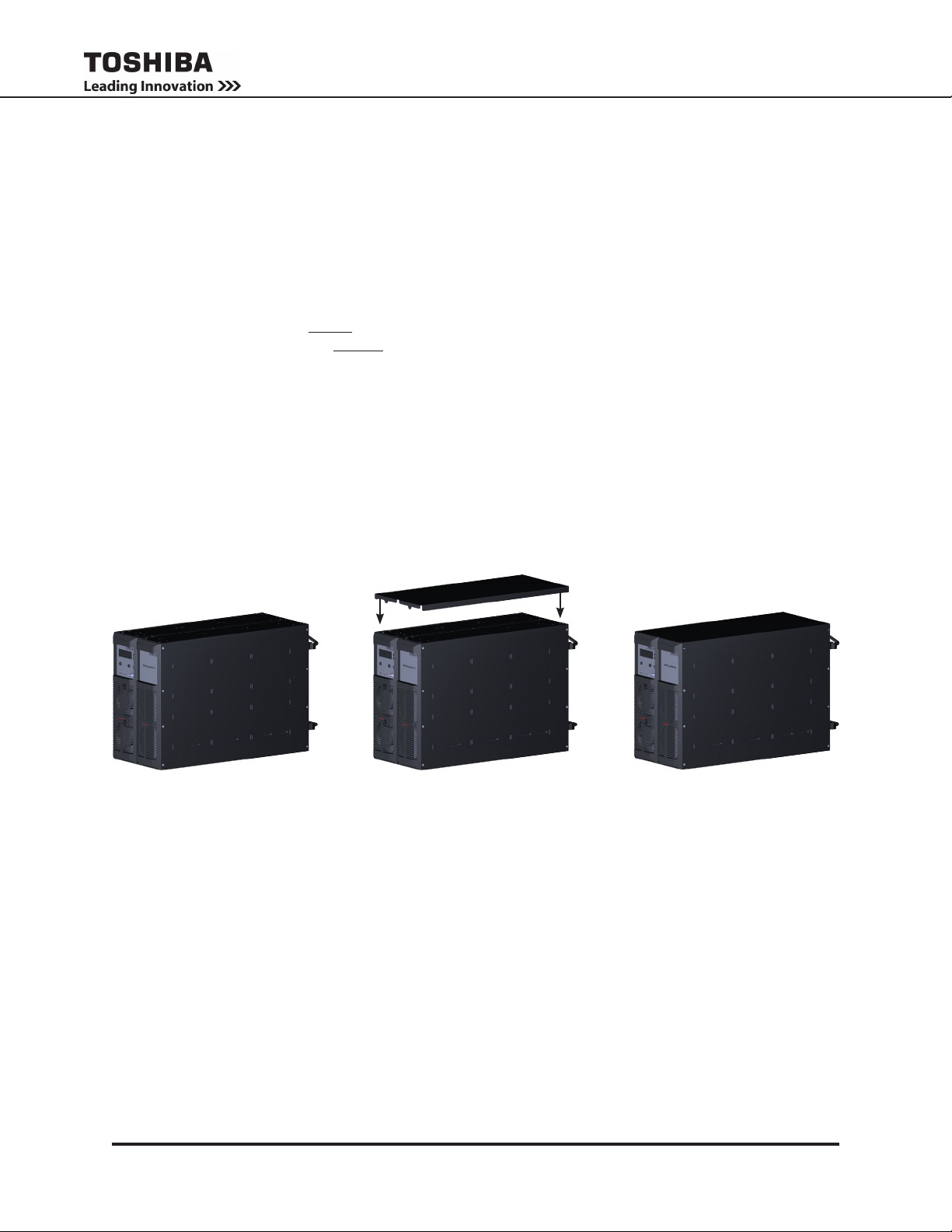
6.3 Tower Installation with Cap
The Tower conguration modules are arranged side by side, and secured by a press-t cap over the assembly. If the optional Caster Kit is available, see Appendix E2 for installation.
1. Unpack the T1000 modules and set them in the desired location with the faceplates at the top as
shown below.
2. Facing the front of the modules, arrange them left to right in the following order (See Fig. 6-1 - 6-4):
• Transformer Module (if available)
• Power Module
• Battery Module with output panel(if available)
• Second Battery Module without output panel (if available)
NOTE: There is a Tower Cap for 2-, and 3-module tower systems. Fig. 6-7 shows Tower Cap installation for a 2-module system.
3. Press the T1000 Tower Cap over the tower modules (Fig. 6-7).
4. The T1000 tower is ready for interconnecting cable installation.
5. Go to Section 7 for cabling instructions.
A CB
FIGURE. 6-7: INSTALL CAP ON TWO MODULE TOWER SYSTEM
12
T1000 Series UPS Installation and Operation Manual – 91074-002
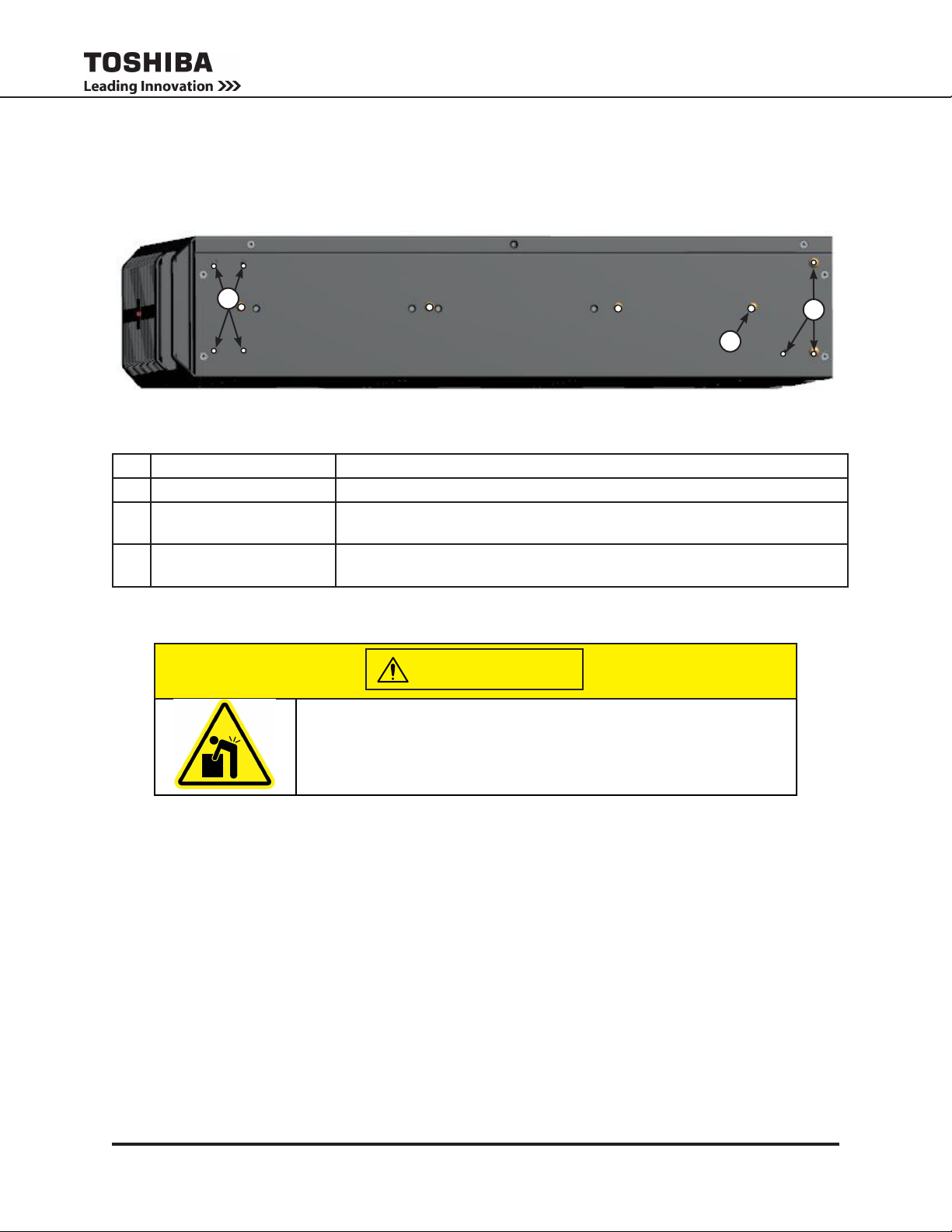
6.4 Rackmount Installation - Bracket Mounting Holes
The Power Module, Battery Module, and Transformer Module all come with the mounting bracket holes
located symmetrically on each side. See Fig. 6-8 for the hole locations. Table 6-1 lists the mounting hardware for the bracket holes.
1
3
FIGURE. 6-8: RACKMOUNT BRACKET MOUNTING HOLES
TABLE 6-1 RACKMOUNT BRACKET MOUNTING HOLES AND HARDWARE
No. Accepts (per side) Used for
1 4 x Phillips 8-32 x 1/4” Mount for front bracket 68844 used for 4-Post xed mounting
2 3 x Phillips 8-32 x 1/4” Mount for rear bracket 92746 used for 4-Post Fixed Mounting Brackets
(Kit 92802),
3 1 x Phillips 10-32 x 1/2” Mount for rear bracket 92746 used for 4-Post Fixed Mounting Brackets
(Kit 92802),
2
CAUTION
Heavy object
Can cause muscle strain or back injury.
Use lifting aids and proper lifting techniques when handling or
installing T1000 Modules.
6.5 4-Post Rack Installation Instructions
Use the 4-Post Fixed Rackmount Kit 92802 (1 kit per module) to mount the T1000 module in a 19-inch,
4-Post rack as follows.
Contents - Fixed 4-Post Rack Installation Kit (92802)
1 ea.: T1000 Fixed 4-Post Rack Installation Instructions - 94036
2 ea.: 68844 - Ear Chassis Mounting
2 ea.: 92746 - Bracket, Rear Fixed Mounting, 4-Post, Black
(Hardware Kit 93863)
12 ea.: Cage Nut, 1/4”-20
12 ea.: Hex bolt, Sems, 1/4”-20 x 5/8”
12 ea.: Screw, PHP (Pan Head Phillips) 10-32 x 1/2” St Box
4 ea.: Screw, PHP 8-32 x 1/4” St Zi
Prepare the 4-Post Rack
1. Clip the cage nuts (PC76315P501 Cage Nut, 1/4”-20) from the 93863 kit over the rack rail mounting
T1000 Series UPS Installation and Operation Manual – 91074-002
13
holes at the desired level. Clip 2 cage nuts spaced vertically 4 in. apart on each Post.
2. If more than one module is being installed for the T1000 system, install the next pair of cage nuts 3
Rack Units (5 1/4”) above the rst set of cage nuts for the next module.
3. Repeat Steps 1-2 for each T1000 module to be installed. Continue until cage nuts for all the modules
in the system have been clipped on the 4-Post rack.
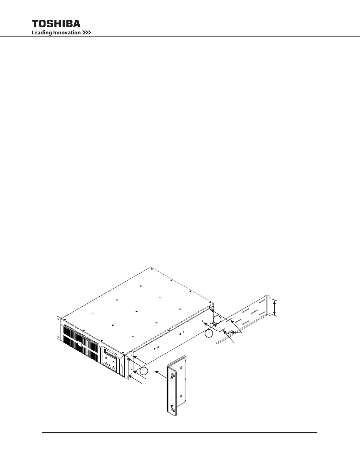
Prepare the Module(s)
4. Attach the front and rear bracket to the left and right sides of the T1000 module as shown in Fig. 6-9.
Use the mounting hardware from Kit 93863 to secure the brackets to the mounting holes indicated in
Fig. 6-8 and Table 6-1.
5. Secure the Front Brackets, P/N 68844, to the left and right front side of the module at Fig. 6-9 (1) using
four Phillips 8-32 x 1/4” screws.
6. Secure the Rear Brackets, P/N 92746, to the left and right rear side of the module at Fig. 6-9 (2) using
1 Phillips 8-32 x 1/4” screw each in the top and bottom slot, and use a Phillips 10-32 x 1/2” in the center
slot (Fig. 6-9 (3)).
Install the Module(s) in the 4-Post Rack
CAUTION: Battery Modules weight 150 lb. (68 kg). Use lifting aids and proper lifting techniques.
7. Follow the vertical arrangement of T1000 modules as discussed in Section 6.1. Mount the lowest module in the 4-Post rack to the bottom pair of cage nuts on each Post using the 1/4”-20 x 5/8” hex bolts,
(P/N 33798).
8. Repeat Step 7 for the remaining modules, working from bottom to top. (Fig. 6-10)
9. Go to Section 7 for cabling instructions.
14
Rear Bracket
92746
2
3
Center Slots - use one ea.
Phillips 10-32 x 1/2” screws
Front Bracket
1
4 in.
FIGURE. 6-9: FIXED MOUNTING BRACKETS - 4-POST RACK
T1000 Series UPS Installation and Operation Manual – 91074-002
68844
Four ea.
Phillips 8-32 x 1/4” screws
4 in.
Side Slots - use two ea.
Phillips 8-32 x 1/4” screws

FIGURE. 6-10: 4-POST RACK - FIXED
T1000 Series UPS Installation and Operation Manual – 91074-002
15
7. Wiring the System
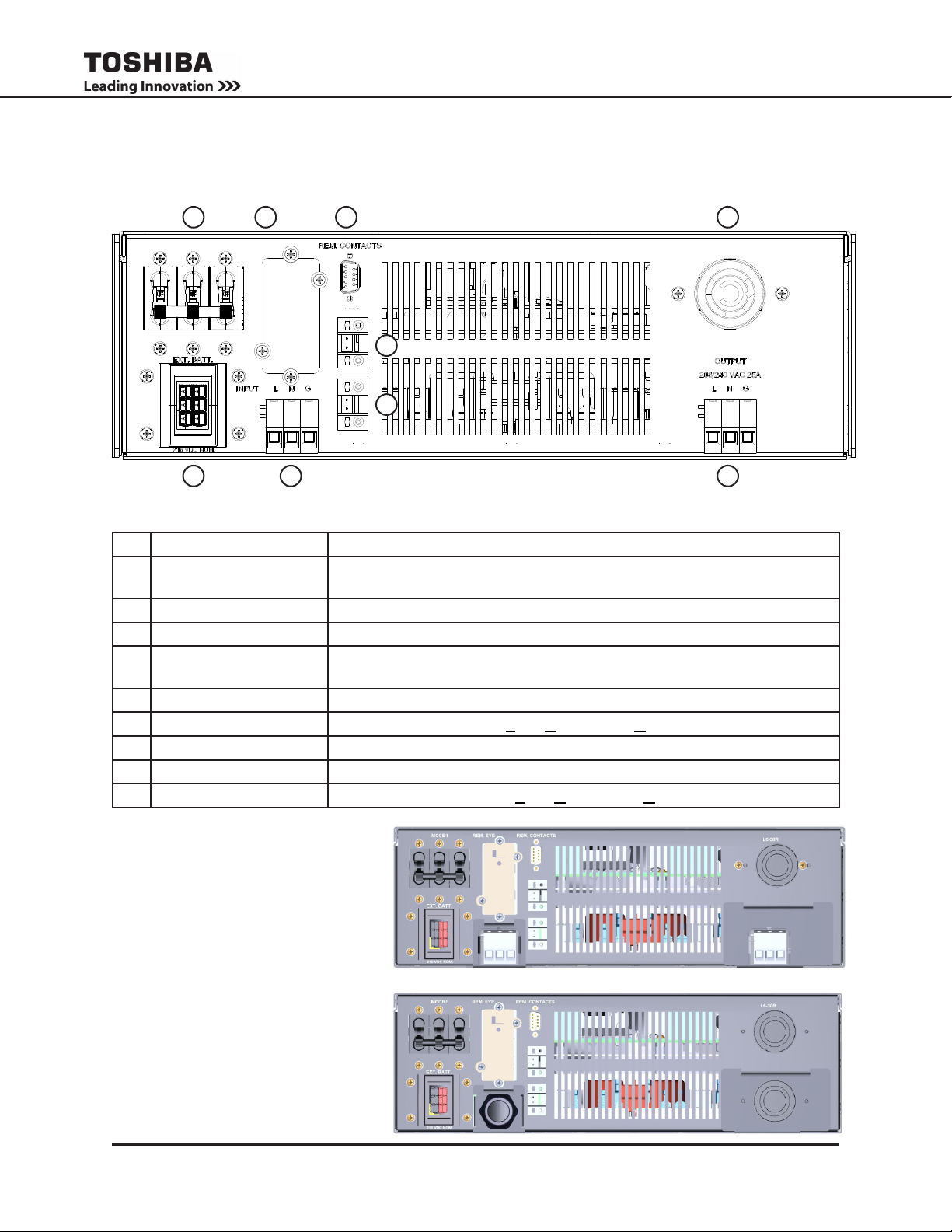
7.1 Layout - Power Module
1 2
INPUT MCCB1
208V/240VAC 30A
REMOTEYE
EPO 240V
REM. STOP
43
USE COPPER 75°C MIN.
CONDUCTORS ONLY
8
SEE INSTRUCTION MANUAL FOR WIRING
TERMINATION AND TIGHTENING TORQUE
OUTPUT L6-30R
208/240VAC 25A
7
65
FIGURE 7-1: POWER MODULE BACK PANEL LAYOUT
9
TABLE 7-1: POWER MODULE BACK PANEL LAYOUT
No. Label Function
1 INPUT MCCB1
Main On/Off circuit breaker.
208V/240VDC 30A
2 REMOTEYE Cover plate for RemotEye® circuit card slot.
3 REM. CONTACTS Dry contacts DB9 connector.
4 OUTPUT L6-30R
Output receptacle for L6-30P cord (alternate output for 208/240 only)
208/240VAC 25A
5 EXT. BATTERY External Battery Module Anderson receptacle.
6 INPUT L N G Hardwire input terminals Line, Neutral, and Ground. (TB1)
7 REM. STOP Remote Stop Contacts. (TB4) (10 VDC)
8 EPO 240V Remote Emergency Power Off (EPO) Contacts. (TB3) (240/208 VAC)
9 OUTPUT L N G Hardwire output terminals Line, Neutral, and Ground. (TB2)
FIGURE 7-2: POWER MODULE -
HARDWIRED CONFIGURATION
(P/N T1P0A6000GVG,
T1P0A6000GVGR3)
3-Post Input Terminal Block, and
one each 3-Post Output Terminal
EPO 240V
REM. STOP
Block and NEMA L6-30R outlet.
FIGURE 7-3: POWER MODULE WITH
6-50P LINECORD (-L1) OPTION
(P/N T1P0A6000GVGL1,
T1P0A6000GVGR3L1)
Input Power Cord #10-3SO 6-50P
and two each NEMA L6-30R outlets.
16
EPO 240V
REM. STOP
T1000 Series UPS Installation and Operation Manual – 91074-002
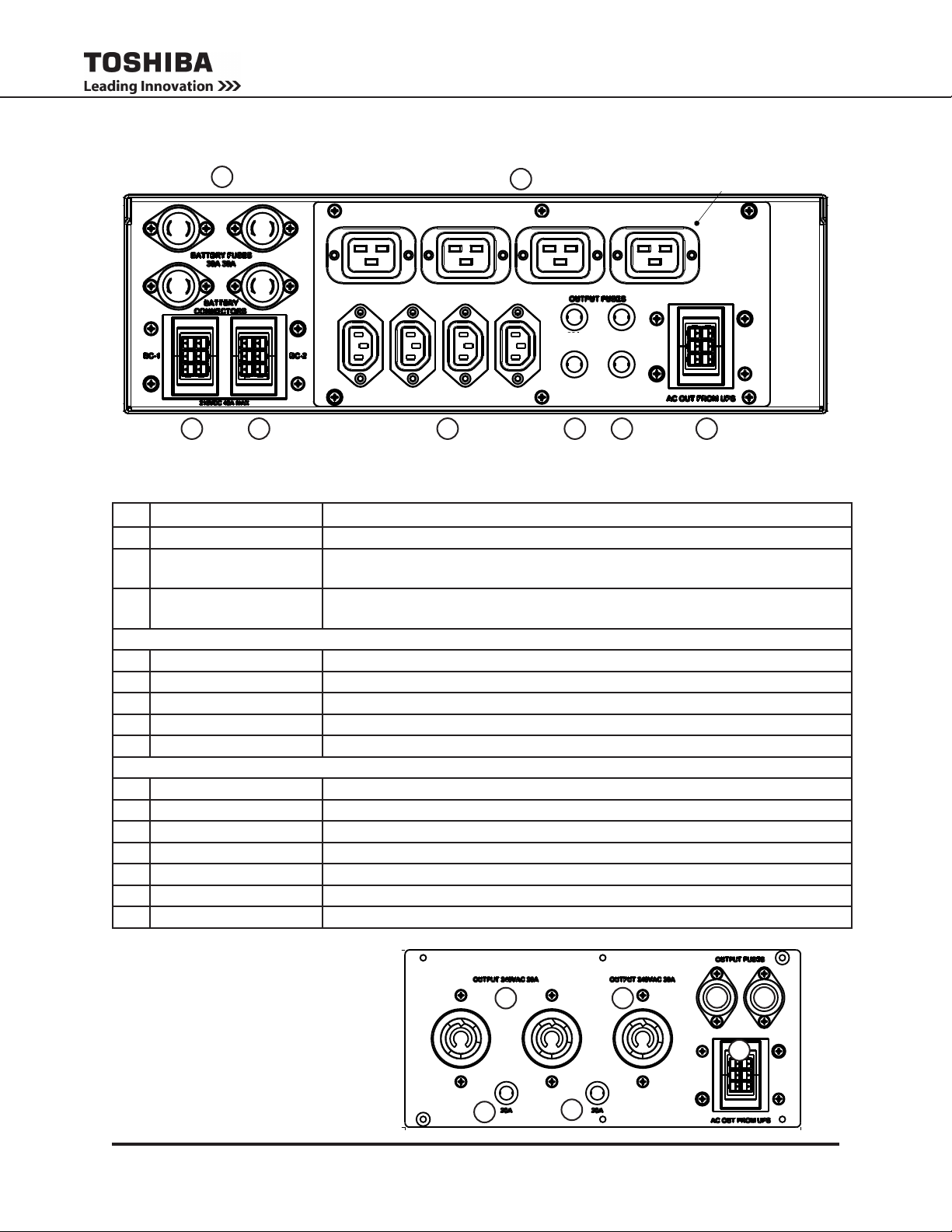
7.2 Layout - Battery Module (w/ Outlet Panel)
O/P PANEL C-13 & C19
905000
1
OUTPUT 240VAC 10A
CN12A CN12B
4
OUTPUT 240VAC 15A
10A
10A
15A
15A
6532 7 8
FIGURE 7-4: BATTERY MODULE WITH P1 OUTLET PANEL - LAYOUT
TABLE 7-2: BATTERY MODULE - BACK PANEL LAYOUT
No. Label Function
1 BATTERY FUSES Battery Fuses, 4 ea. (500V, 30A)
2 CN12A Battery cable Anderson Receptacle (w/ Int. Thermistor) - Connect to Power
Module “Ext. Battery”.
3 CN12B Battery cable Anderson Receptacle - Connect to second Battery
Module CN12A or CN12B
P1 OPTIONAL OUTLET PANEL 91425: C-13 & C-19
4 OUTPUT 240VAC 15A Outlet Receptacles: 4 ea. IEC C-19, (250V, 20A N. Aamerica., 15A INT.).
5 OUTPUT 240VAC 10A Outlet Receptacles: 4 ea. IEC C-13, (250V, 10A N.Aamerica., 10A INT.).
6 OUTLET FUSES 15A Outlet Fuses for IEC C-19 receptacles. (250V, 15A)
7 OUTLET FUSES 10A Outlet Fuses for IEC C-13 receptacles. (500V, 10A)
8 AC OUT FROM UPS Anderson receptacle for UPS output cable.
P2 OPTIONAL OUTLET PANEL 91427: NEMA L6-20R & L6-30R
8 AC OUT FROM UPS Anderson receptacle for UPS output cable.
9 OUTPUT 240VAC 20A Outlet Receptacles: 2 ea. NEMA L6-20R, (250V, 20A).
10 OUTPUT 240VAC 30A Outlet Receptacle: 1 ea. NEMA L6-30R, (250V, 30A).
11 OUTLET FUSE 20A Outlet Fuse for NEMA L6-20R receptacle (250V, 20A).
12 OUTLET FUSE 20A Outlet Fuse for NEMA L6-20R receptacles (250V, 20A).
13 OUTLET FUSE 30A Outlet Fuses for NEMA L6-30R receptacle (500/600V, 30A).
14 OUTLET FUSE 30A Outlet Fuses for NEMA L6-30R receptacles (500/600V, 30A).
FIGURE 7-4: BATTERY MODULE
OUTPUT PANEL P2 - LAYOUT
9
11
T1000 Series UPS Installation and Operation Manual – 91074-002
12
10
13
14
20A 30A
8
17
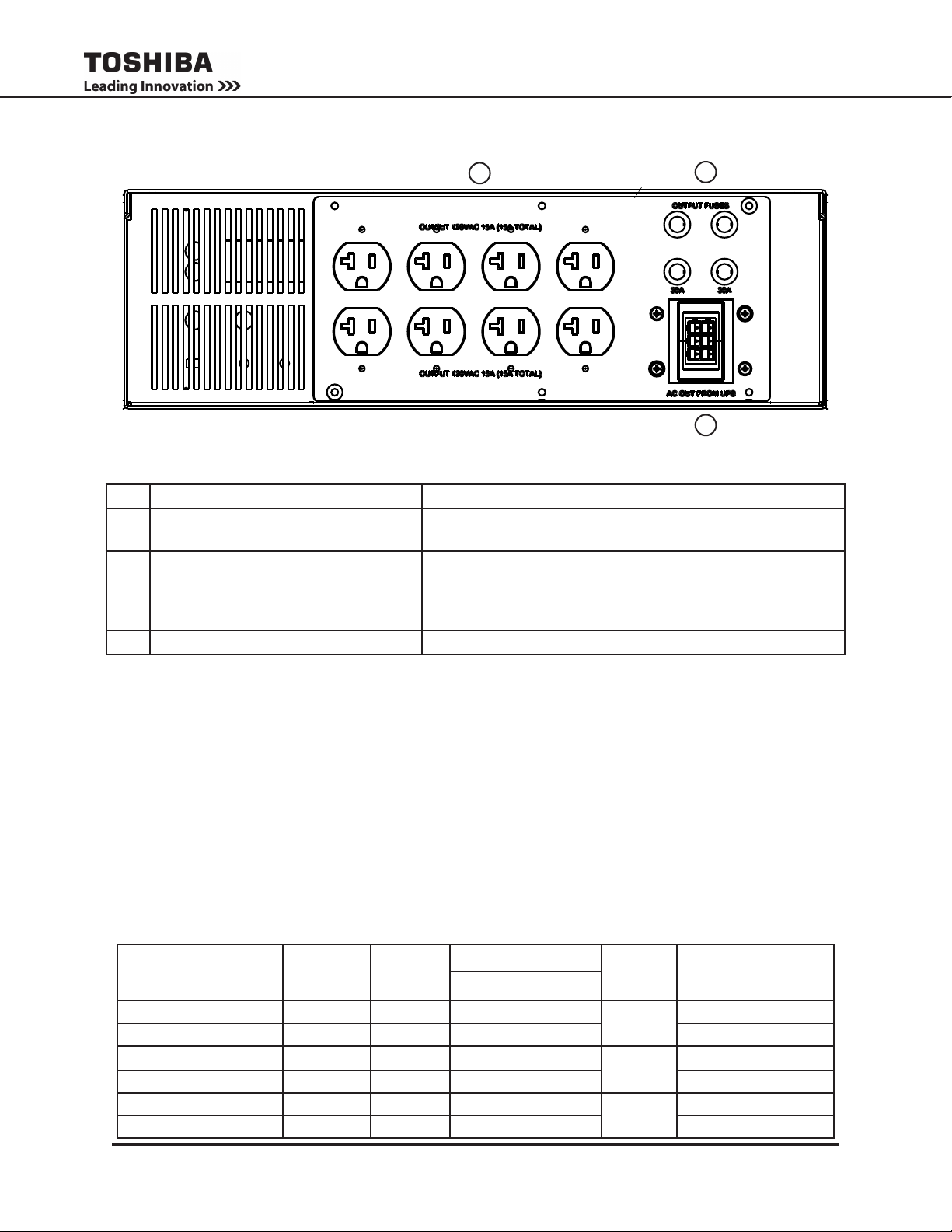
7.3 Layout - Transformer Module
OUTPUT PANEL 8X 5-20R
91426
4.875
10.875
4.875
10.875
C-13, (250V 15A) & C-19, (250V 20A)
NEMA 5-20R, (125V 20A) (XFMR MODULE)
NEMA L6-20R, (250V 20A) L6-30R, (250V 30A)
BLANK PANEL
ASSY: 91427; PANEL: 90502
ASSY: 91425; PANEL: 90500
1
2
FIGURE 7-5: TRANSFORMER MODULE - BACK PANEL LAYOUT
TABLE 7-3: TRANSFORMER MODULE BATTERY MODULE - BACK PANEL LAYOUT
No. Label Function
1 OUTPUT 120VAC 20A Output Receptacle Panel: 4 duplex NEMA 5-20R (250V,
2 OUTPUT FUSES Fuses, 4 ea. ,(250V, 20A)
3 AC OUT FROM UPS Anderson receptacle for UPS output cable.
7.4 Power Module Cable Size and Tightening Torque
The Battery Modules and Transformer modules come with their own inter-module cabling included.
See Fig. 7.5.
Only the Power Module Input terminals need to have wiring installed.
The Power Module Output terminal wired using either:
• Factory-supplied inter-module cables
• Customer-supplied hardwire cables
Use the following table to select the recommended wire size and terminal lug tightening torque for I/O wire
connections.
3
20A)
(4 Line fuses, one for each pair NEMA 5-20R. Total current
limit for each pair receptacles is 20A.
Total output from all receptacles must not exceed 50 A)
TABLE 7-4: POWER MODULE CABLE SIZING AND TERMINAL TORQUE SPECIFICATIONS- HARDWIRE
Terminal
AC Input Line, Neutral L, N 24 - 6 10 - 8 0.43 in
AC Input Ground G 24 - 6 10 - 8 11 - 21 (1.2 - 2.4)
AC Output Line, Neutral L, N 24 - 6 10 - 8 0.43 in
AC Output Ground G 24 - 6 10 - 8 11 - 21 (1.2 - 2.4)
EPO Switch (Plug) 30 - 12 18 - 16 0.27 in
Remote Switch (Plug) 30 - 12 18 - 16 3.5 - 4.4 (0.4 - 0.5)
18
(USE COPPER 75°C MIN. CONDUCTORS ONLY)
Terminal
Number
Terminal
Capacity
(AWG)
Recommended Wire
T1000 Series UPS Installation and Operation Manual – 91074-002
6 kVA
Stripping
Length
in (mm)
(11 mm)
(11 mm)
(7 mm)
Tightening Torque
lb.-in. (N•m)
11 - 21 (1.2 - 2.4)
11 - 21 (1.2 - 2.4)
3.5 - 4.4 (0.4 - 0.5)
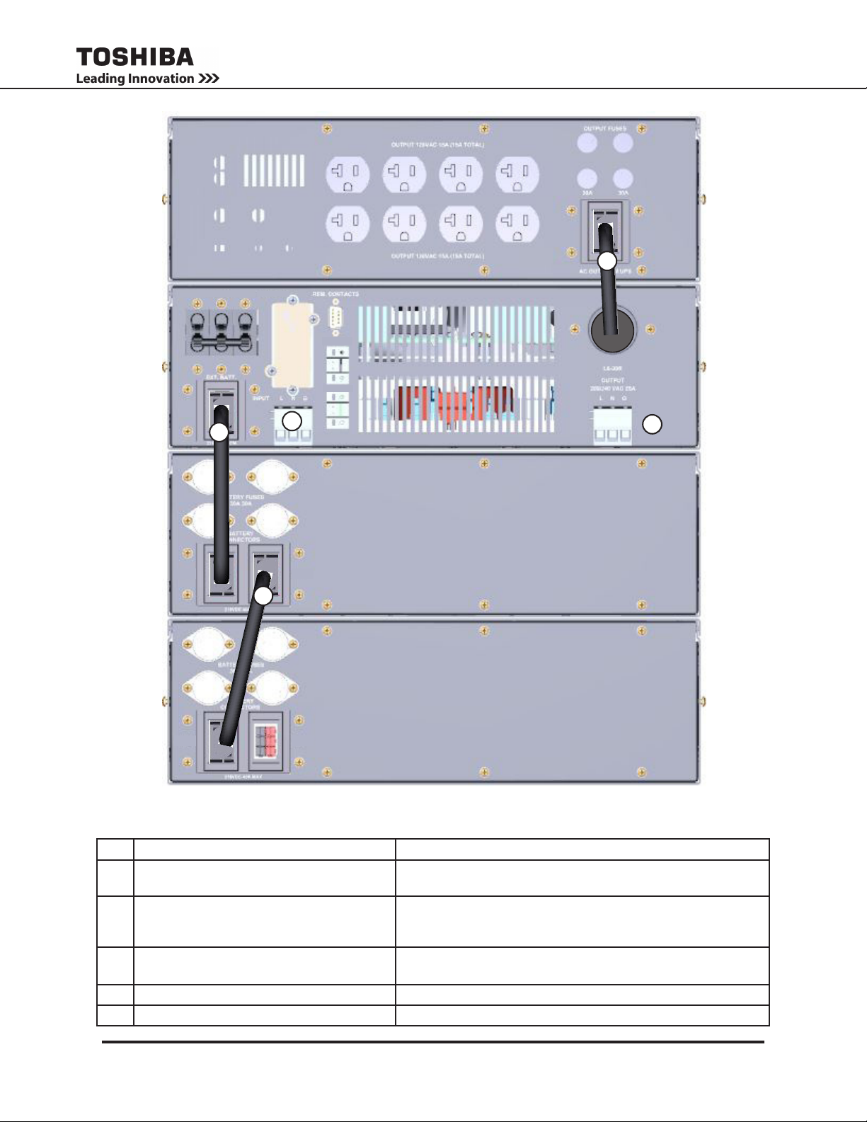
3
INPUT MCCB1
CN12A CN12B
REMOTEYE
1
5
2
EPO 240V
REM. STOP
4
CN12A CN12B
FIGURE 7-5: FACTORY SUPPLIED CABLING GUIDE - W/ 120V XFMER MODULE
TABLE 7-5: 120V SYSTEM CABLING SPECIFICATIONS
No. Item Function
1 92855 Battery Connector Cable Factory Supplied - Connects Power Module EXT BATT to Batt
Module BC1 CN12A to using keyed Anderson Connectors.
2 92855 Battery Connector Cable Factory Supplied - Connects Batt Module BC1 CN12B to either
Batt Module BC2 CN12A or Batt Module BC2 CN12B using
keyed Anderson Connectors.
3 92858 (240V) and 92883 (208V) Power
Module L6-30 Output to Xfmr Module Cable
4 TB2 240V Hardwire Output User Supplied (two wire plus ground)
5 TB1 240V Hardwire Input User Supplied (two wire plus ground)
T1000 Series UPS Installation and Operation Manual – 91074-002
Both Factory Supplied - L6-30P twistlock to Xfmr Module keyed
Anderson Connector.
19
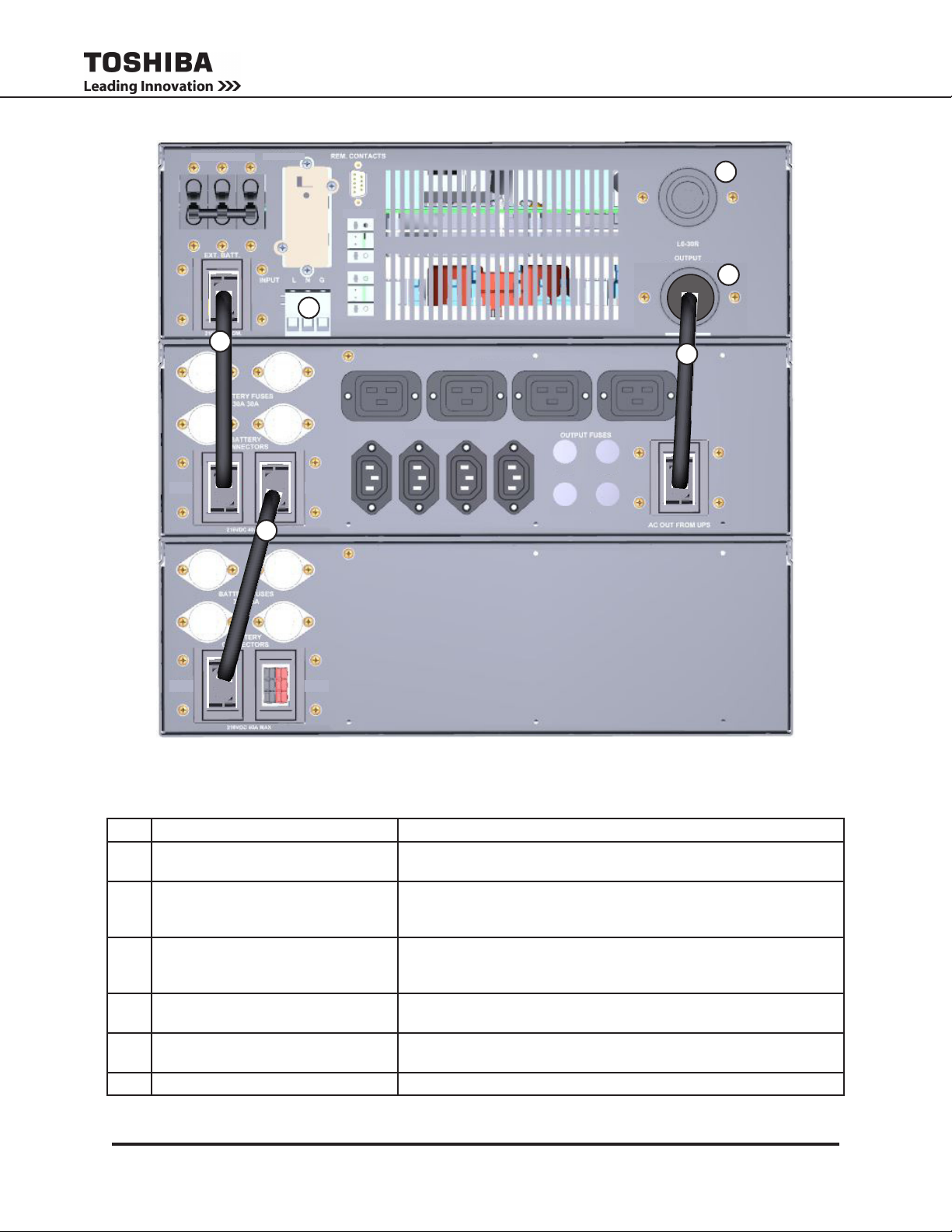
INPUT MCCB1
REMOTEYE
5
EPO 240V
6
1
CN12A CN12B
2
CN12A CN12B
REM. STOP
OUTPUT 240VAC 10A
OUTPUT 240VAC 15A
10A 15A
10A
4
3
15A
FIGURE 7-6: FACTORY SUPPLIED CABLING GUIDE - W/ BC OUTPUT PANEL
TABLE 7-6: 240V SYSTEM CABLING SPECIFICATIONS
No. Item Function
1 92855 DC Connector Cable: Batt
Module 1 to Pwr Module
2 92855 DC Connector Cable: Batt
Module 1 to Batt Module 2
3 92858 AC Connector Cable: Power
Module L6-30R Output to Batt Mod-
ule Output Panel P1/P2
4 Output L6-30R Receptacle Panel User Selectable - Can be either a L6-30 Receptacle or a 3-Post, 3
5 Output L6-30R Receptacle Accommodates L6-30P twistlock cord (alternate output for 208/240
6 TB1 240V Hardwire Input User Supplied (two wire plus ground)
20
Factory Supplied - Connects Power Module EXT BATT to Batt Module
BC1 CN12A to using keyed Anderson Connectors.
Factory Supplied - Connects Batt Module BC1 CN12B to either Batt
Module BC2 CN12A or Batt Module BC2 CN12B using keyed Ander-
son Connectors.
Both Factory Supplied - L6-30P twistlock to Xfmr Module keyed Anderson Connector.
wire terminal 240V output.
only).
T1000 Series UPS Installation and Operation Manual – 91074-002
 Loading...