

Page 1
In Touch With Tomorrow
Adap
Programmable Controllers
TOSHIBA INTERNATIONAL CORPORATION
13131 West Little York Road
Houston, TX 77041
PH. 800 231- 1412, 713-466-0277 FAX 713-466-8773
E-Mail plc@tic.toshiba.com
MODEM COM MUNICATIONS WITH THE T1 AND T2E/T2N
March 1998
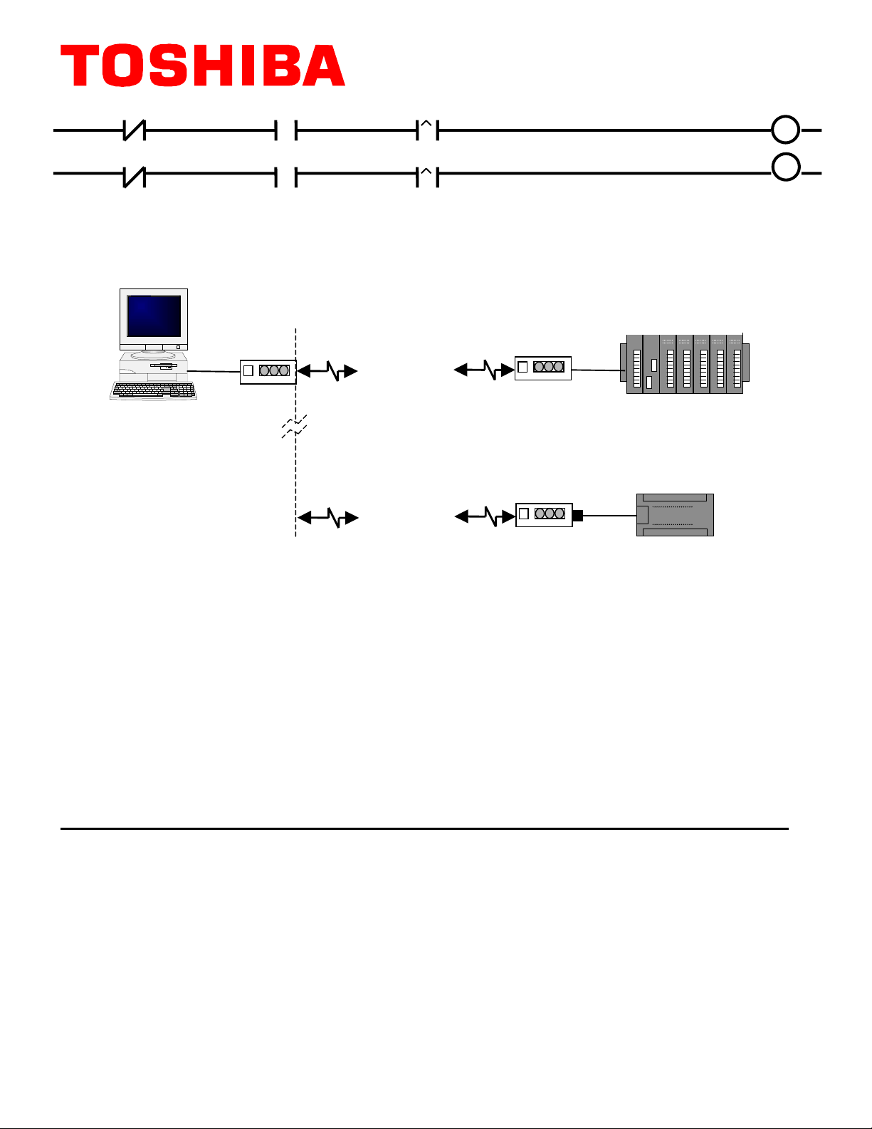
USING T-PDS WINDOWS FOR DIAL–UP COMMUNICATIONS WITH TOSHIBA
T1 AND T2E/T2N PROGRAMMING PORT
Master Computer
T2E/T2N PLC
Modem
Telephone
Line
Different
Ph. Numbers
Stored in T-PDS
Software
Telephone
Line
Modem
Modem
w/Null
Modem
ter
RS232
RS232
T1/T1S PLC
T1
T1
T1T1
Toshiba PLC users can expand their remote diagnostics and remote programming capabilities
by using Hayes compatible modem communications over the Public Switched Telephone
Network with standard analog phone lines and standard modems. Please note that “analog” line
means a normal dial-in dial–out phone line similar to the ones that you have at home (i.e., about
48Vdc open circuit voltage with about 110Vac ring voltage). This does
phone lines in
most offices
that use modern digital PBX systems. Plugging a modem directly into
not
include the digital
one of these digital office lines may destroy the modem.
We used US Robotics 56K Sportster external modems for our tests, but just about any external
Hayes compatible modem will work. Here is the list of equipment that you need for modem
communications with the PLC’s programming ports:
Accessories For T2E/T2N Modem Communications (with programming port):
PC Side
• a ≥ 9600 baud external modem.
PLC Side
:
• a standard “straight-through” 9-25 pin RS-232 serial cable
:
• a standard “straight-through” 9-25 pin RS-232 serial cable
• a ≥9600 baud external modem.
See Note 1 on page 5
Page 2
Accessories For T1 Modem Communications (with programming port):
PC Side
PLC Side
See Note 2 on page 5
Now that we have discussed the basic hardware requirements, let’s look at the parameter settings
in T-PDS and the PLCs. We will need to use the Computer Link connection when communicating
via modem, as the “Direct” connection will not work.
note; see the last page for more details. There are 3 Setup Steps:
:
• a standard “straight-through” 9-25 pin RS-232 serial cable;
• a ≥ 9600 baud external modem.
:
• a standard “straight–through” 9-25 pin RS-232 serial cable;
• a “null-modem” adapter such as Radio Shack’s 9-9 pin Null Modem
• a Toshiba part number TKRS232T1 T1 programming cable
• a ≥ 9600 baud external modem.
T-PDS version 1.2
is used in this application
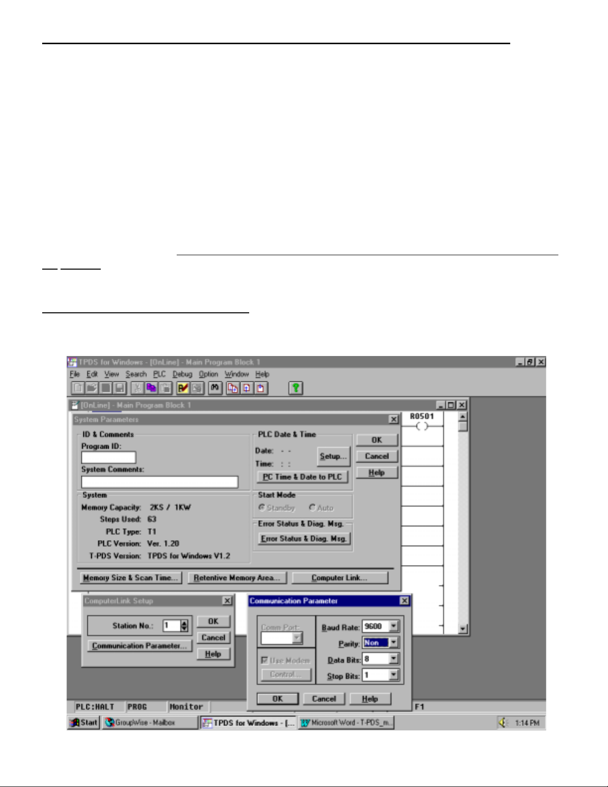
STEP 1: CONFIGURE THE PLC
First, let’s set up the PLC’s Computer Link parameters. Go
the normal “Direct” method. We will need to open the System Parameters screen as shown below:
Online
with the T1 or T2E/T2N using
Page 2
Page 3
Click on the “
Computer Link
” button in the System Parameters screen, and the “ComputerLink
Setup” menu will appear. Select a station number for the PLC, then click the “
Parameter
” button . Select “NON” parity setting, and then click the “OK” buttons. When the “Write
OK” screen appears, click “OK.”
Communication
Now go to the PLC/Memory Management menu and select “
Link parameters will now be stored in EEPROM memory. If you have a T2E, set the “
Write to EEPROM
.” The Computer
COM
” dip
switch on the front of the module to the right-hand position and then cycle power on the PLC. This
will set the T2E programming port up for no parity.
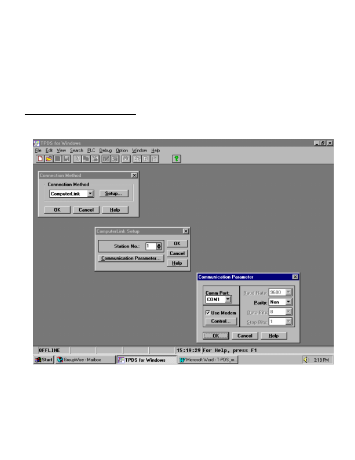
STEP 2: CONFIGURE T-PDS:
Now that the PLC configuration is done, we will now do the T-PDS configuration on the PC. We
will need to go “Offline” and set the T-PDS communication parameters as follows:
Go to the Options/Communication menu and set the above parameters. Remember that we set
the PLC Computer Link station address as 1 on the previous page. Be sure to select “
here. Check the “
Use Modem
” box and click the “
Control
Page 3
” button to get to the next screen.
NON
” parity
Page 4

Now let’s go to the Modem Control box and finish the T-PDS configuration. The Modem Control
box is a handy database that will store a remote site name, modem initialization parameters, and
the phone number of the remote site. You can move between the fields using the TAB key.
The most important parameter here is the “
out or disconnect without this. The parameter shown here is the "
Initialize
” parameter. T-PDS will not successfully dial
S25
” register which controls the
time that the PC modem can have a DTR loss before hanging up. Since T-PDS toggles the DTR
line on the COM port during modem connection and hang-up, this parameter must be set to
accommodate your modem. The setting of
S25 = 50
worked on the US Robotics modems. Of
course, you must also enter the number of the site to be called. Save your work and click the
appropriate “OK” buttons.
Page 4
Page 5

STEP 3: CONFIGURE THE PLC’s MODEM :
Now that T-PDS is configured, we are ready for the last part of our setup procedure which is to
initialize our remote PLC modem. We suggest that you connect your PC to the PLC’s modem with
the straight-through 9-25 pin RS-232 cable, and open up Windows Terminal (or similar). Set up
the terminal program for 9600 baud, 8 data bits, 1 stop bit, no parity. Once the terminal connection
is opened, you can begin to set the parameters in the PLC’s modem. There are two parameters
that you
commands and hit ENTER. You can then store these parameters in the modem’s non-volatile
memory by typing the command
cause the remote modem to ignore DTR, and the S0=1 command will tell the remote modem to
answer on the first ring. No setup is required for the PC modem.
After the PLC’s modem has been initialized, connect all the cables and you will be ready to dial
into the remote PLC. Just go “
Choose “
establish carrier, or will not hang up when you go “OFFLINE,” then adjust your DTR timeout
parameter (S25 on USR modem).
If you are using a T1, remember to attach the null-modem module to the modem’s RS-232 cable.
Also, in the T1 version ≥1.2 as well as the Super T1-40, register SW038 is the Computer Link
Response Delay setting which can be used with the default setting of 30 (for a 300 ms delay) or
can be lowered if needed. The default setting worked for our tests.
need
to set in the PLC’s modem:
AT&W0
ONLINE
YES
” and T-PDS will start to dial out. If T-PDS hangs up as soon as the modems
AT&D0
and then hitting the ENTER key. The &DO command will
” and a box will appear that says “
and
ATS0=1
. Type in each of these
Dialing…..YES.…NO
.”
NOTES:
Note 1:
This setup will work on all T2E and T2N series PLCs. If you have an earlier version
of the T2 (pre T2E), then you must use a special modem that supports Odd parity.
You could also use the RS-485 Computer Link port with a standard modem, but you
will need an RS-485 to RS-232 converter.
Note 2:
This setup for the T1 will work if you have a T1 with firmware version 1.2 or greater.
This version allows you to use the Computer Link protocol with a no-parity setting.
If you have a T1 with earlier firmware, you must use a special modem that supports
Odd parity. T1s whose first two digits of the serial number are less than “64” will not support
modem communications.
Note 3:
It is recommended that both modems be from the same manufacturer. This simplifies setup and
minimizes potential compatibility problems.
Note 4:
Page 5
Page 6

When the programming port is set to non parity, only the T-PDS software (and the modem) can
communicate with the PLC. Furthermore, the T-PDS software must also be setup for non parity.
Note 5:
For T-PDS versions prior to Ve r 1.2 contact Toshiba for upgrade eligibility.
A SPECIAL NOTE FOR USERS THAT HAVE OLDER T1’s, T2’s, and T3’s WHOSE
PROGRAMMING PORTS DO NOT SUPPORT A “NO-PARITY” SETTING
If you have one of these PLCs and would like to use modem communications, you must use a
modem that supports odd parity. This will apply if you have a T1 with firmware version earlier than
1.2, or any of the T2 series that is not a T2E/T2N. Most T3’s will also require an odd parity
modem. One source for these modems is TELENETICS, ph: (714)455-4000; fax (714)455-4010.
Telenetics model number MIU14.4-11B-9600 should be an appropriate modem to use.
You can use the same configuration methods as shown in this note, just select “Odd” parity
Instead of “Non” parity.
Page 6
 Loading...